EP2492669A1 - Probengefäss für kalorimetrische Messungen - Google Patents
Probengefäss für kalorimetrische Messungen Download PDFInfo
- Publication number
- EP2492669A1 EP2492669A1 EP12156297A EP12156297A EP2492669A1 EP 2492669 A1 EP2492669 A1 EP 2492669A1 EP 12156297 A EP12156297 A EP 12156297A EP 12156297 A EP12156297 A EP 12156297A EP 2492669 A1 EP2492669 A1 EP 2492669A1
- Authority
- EP
- European Patent Office
- Prior art keywords
- sample vessel
- cavity
- sample
- receptacle
- vessel according
- Prior art date
- Legal status (The legal status is an assumption and is not a legal conclusion. Google has not performed a legal analysis and makes no representation as to the accuracy of the status listed.)
- Granted
Links
Images


Classifications
-
- G—PHYSICS
- G01—MEASURING; TESTING
- G01N—INVESTIGATING OR ANALYSING MATERIALS BY DETERMINING THEIR CHEMICAL OR PHYSICAL PROPERTIES
- G01N25/00—Investigating or analyzing materials by the use of thermal means
- G01N25/20—Investigating or analyzing materials by the use of thermal means by investigating the development of heat, i.e. calorimetry, e.g. by measuring specific heat, by measuring thermal conductivity
- G01N25/22—Investigating or analyzing materials by the use of thermal means by investigating the development of heat, i.e. calorimetry, e.g. by measuring specific heat, by measuring thermal conductivity on combustion or catalytic oxidation, e.g. of components of gas mixtures
- G01N25/26—Investigating or analyzing materials by the use of thermal means by investigating the development of heat, i.e. calorimetry, e.g. by measuring specific heat, by measuring thermal conductivity on combustion or catalytic oxidation, e.g. of components of gas mixtures using combustion with oxygen under pressure, e.g. in bomb calorimeter
-
- G—PHYSICS
- G01—MEASURING; TESTING
- G01K—MEASURING TEMPERATURE; MEASURING QUANTITY OF HEAT; THERMALLY-SENSITIVE ELEMENTS NOT OTHERWISE PROVIDED FOR
- G01K17/00—Measuring quantity of heat
- G01K17/006—Microcalorimeters, e.g. using silicon microstructures
Definitions
- the present invention relates to sample vessels, such as crucibles, high-pressure crucibles, autoclaves (also called “bombs”) or measuring cells, for calorimetric and thermoanalytical measurements according to the preamble of patent claim 1.
- Thermal analysis and microcalorimetry are used in particular in research, in quality control and for the clarification of the thermal safety of chemical production processes.
- Thermoanalytical and calorimetric measurement methods such as differential scanning calorimetry, can be used to detect the temperature at which a sample converts or reacts and how large the amount of heat required for this, or how much heat is released.
- reactants, products and reaction mixtures are examined at different stages of the reaction by means of microcalorimetry in order to be able to quantitatively measure the thermal risk of the production process.
- a sample is placed in a sample vessel and preferably sealed pressure-tight.
- the sample vessel is subjected to a temperature program with the sample, and the thermal behavior is observed.
- the sample vessel must be able to withstand a high pressure in certain cases and is then designed as a high-pressure crucible.
- it should have as small a mass as possible in order to achieve the highest possible measuring sensitivity guarantee. Too large a mass of the sample vessel impairs the measurement by making it impossible for the acquisition of fast phenomena by its sluggish temperature behavior and also limits the heating rate and thus the number of measurements carried out per time.
- a disposable sample vessel made of gilded steel has proven itself, which can withstand a pressure of up to 200 bar.
- This sample vessel consists of a receptacle having a cavity, which can be closed with a cover likewise made of gold-plated steel. The closure takes place by cold welding of the sample vessel by pressing the lid into a socket of the receiving vessel of the sample vessel.
- This sample vessel has a mass of 1.5 g with a sample volume of approx. 50 ⁇ l.
- Such sample vessels are for example in the CH 695 709 and the CH 696 370 disclosed.
- the present invention provides a sample vessel for calorimetric measurements comprising a receptacle having a bottom, a circumferential mantle and a cavity bounded by the mantle and the bottom for receiving a sample.
- a sample vessel for calorimetric measurements comprising a receptacle having a bottom, a circumferential mantle and a cavity bounded by the mantle and the bottom for receiving a sample.
- at least one structure is present in the cavity, which serves to homogenize the heat distribution in the sample vessel during a calorimetry measurement.
- the sample vessel may in particular be a high-pressure crucible.
- a high-pressure crucible is generally suitable for being able to withstand a high pressure in the cavity of the receptacle.
- the high-pressure crucible advantageously has a simple and robust design.
- a high-pressure crucible is preferably designed such that it can easily be closed airtight, for which purpose correspondingly designed elements are provided on the receptacle, which provide an airtight closure of the cavity with a closure element, such as e.g. a lid, allow.
- These elements for airtight sealing of the high-pressure crucible may, for example, be a connecting region which is thickened, bead-shaped, grooved, lapped or formed in another suitable manner.
- the hermetically sealed high-pressure crucible typically forms a capsule in which the sample is taken for the thermoanalytical analysis.
- the structure has, in particular, a thermally conductive function, so that it uniformly distributes the heat energy from the interior of the sample vessel to the outside of the sample vessel Sample vessel leads or from the outside of the sample vessel into the interior.
- the structure is also advantageously arranged in the region of the cavity which, when the sample vessel is used as intended, serves to receive the sample to be analyzed.
- the structure is preferably arranged such that it is at least partially surrounded by the sample during a calorimetry measurement.
- the sample vessel may have a lid for closing the cavity, which is usually located with respect to the cavity on the opposite side of the bottom.
- the receptacle is then preferably airtight sealable with the lid, whereby the sample vessel forms a capsule.
- the receptacle and in particular the cavity may have different configurations. In general, however, they both have a substantially cylindrical shape.
- the jacket can essentially have the shape of a hollow cylinder.
- the bottom then preferably forms a flat surface with which the shell encloses a substantially vertical angle.
- other shapes such as a spherical or, although less advantageous, a cuboid or a cube-shaped configuration of the cavity possible.
- the structure is advantageously designed axially symmetrical with respect to a longitudinal axis of the cavity.
- the structure preferably divides the cavity into chambers which are interconnected.
- the structure therefore preferably itself has no self-contained chambers and preferably also forms no self-contained chambers together with the bottom or the jacket.
- the structure subdivides the cavity in such a way that, when the sample vessel is used as intended, in any plane perpendicular to the direction of gravity, all areas of the cavity are interconnected within the same plane.
- the bottom of the sample vessel is usually located at the bottom with respect to the direction of gravity, and the shell extends upwardly therefrom in the direction opposite to the direction of gravity.
- the cavity preferably has a centrally located channel which passes completely through the structure.
- the channel can serve in particular serve to connect the chambers with each other, which are formed by the subdivision of the cavity by means of the structure.
- the cavity generally has a radial direction with an inner diameter.
- the structure extends over at least half of this inner diameter in the radial direction.
- the cavity has a longitudinal axis. He then has along this longitudinal axis a certain length extension, which, if a lid is present, extends from the top of the bottom to the bottom of the lid.
- the structure preferably then extends along the longitudinal axis, in particular preferably continuously, over at least half of the longitudinal extent of the cavity.
- the structure extends along the longitudinal axis even over the substantially entire longitudinal extent of the cavity.
- the structure substantially completely and uniformly fills the cavity.
- the structure is advantageously connected to the jacket or is applied to this. Also advantageously, the structure is connected to the ground or is located on the ground. Moreover, it is also advantageous if the structure rests against the lid or is connected thereto. As a result, an optimal heat exchange between structure and shell or bottom or lid is possible.
- This connection or concern of the structure on the jacket and / or bottom and / or cover can also serve to increase the mechanical stability of the sample vessel. As a result, with the same mechanical stability, the mass of the sample vessel can be reduced relative to the mass of the sample in order to increase the measurement accuracy of the calorimetric measurement.
- the structure is advantageous even integrally formed with the shell and / or the bottom. But it can also be integrally formed with the lid.
- the bottom and the jacket of the sample vessel are preferably also formed integrally with each other.
- the structure can also be designed as an insert, which can be inserted into the receptacle and can advantageously be clamped into the cavity in order to allow the best possible heat exchange with the shell, the bottom and the cover.
- the structure preferably has a wall thickness which essentially corresponds to the wall thickness of the jacket.
- the structure is formed as a plurality of radial ribs.
- the radial ribs are advantageously arranged at uniform intervals along the Umfssenscardi of the shell, whereby they have a star-shaped arrangement.
- the existing between the ribs chambers then form substantially equilateral triangles viewed in cross-section, which corresponds to an optimal structure for dissipating the heat energy.
- the radial ribs may also have recesses, which in particular may each have an arcuate contour. The arcuate contour can be parabolic in particular.
- the structure can also be designed as a plurality of curved ribs, which, in particular when viewed in cross-section, can describe the shape of a paddle wheel. Another possibility is to form the structure in a spiral shape. The structure then has the shape of a spiral which winds along the longitudinal direction of the cavity from bottom to top.
- the sample vessel can take on different shapes and dimensions depending on the measuring method and measuring instrument.
- the volume of the cavity is preferably between 5 .mu.l and 20 ml, more preferably 5-100 .mu.l for microcalorimetric measurements, 0.1-6 ml for differential thermal analysis and 1 - 20 ml for autoclaves.
- the preferred mass of the sample vessel is 0.22 g to 550 g.
- the mass of the receptacle of the sample vessel is preferably 0.22. 1.5 g, for differential thmeroanalysis 5 to 30 g and for autoclaves 30 to 550 g.
- the receptacle preferably has an inner diameter of 4 mm to 3.0 cm at a height of 3 mm to 6 cm and at a preferred wall thickness of 0.2 mm to 3 mm.
- the inner diameter, the height and the wall thickness are in a cylindrical configuration of the receptacle in the microcalorimetry preferably 4 - 8 mm, 3 - 6 mm and 0.2 - 1.0 mm, in the differential thermal analysis preferably 0.5 - 2.0 cm, 0.5 - 4 cm and 0.2 to 1.5 mm and for autoclaves preferably 0.5 to 3.0 cm, 1 to 6 cm and 0.5 to 3 mm.
- the receptacle is preferably made of steel, in particular of gilded steel.
- the lid of the sample vessel is preferably made of steel, gold-plated steel or pure gold.
- the sample vessel could also be made of a nickel-based alloy, titanium, an aluminum-silicon alloy or even pure aluminum.
- FIGS. 1 to 22 illustrate various embodiments of inventive sample vessels.
- the in the FIGS. 1 to 21 Embodiments shown each relate to sample vessels in the form of high pressure crucibles.
- Identical or similar configured elements of the various embodiments are in the FIGS. 1 to 22 each numbered by the same reference numerals.
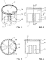
- FIGS. 1 to 4 show in different views a first embodiment of a receptacle 1 of a sample container according to the invention.
- the sample vessel is designed here as a high-pressure crucible and suitable in particular for microcalorimetry measurements.
- the receptacle 1 has a bottom 11, which is planar here and from which extends perpendicular to a circumferential jacket 10 upwards.
- the upper edge of the jacket 10 has a radially outwardly directed bead, which forms a connecting region 14.
- the connecting portion 14 serves to attach one in the Fig. 1 to 4 not shown, with which the receptacle 1 is airtight sealable.
- the lid can protrude into the space surrounded by the shell 10.
- the lid can be attached to the receptacle 1, for example by means of cold welding or by screwing.
- the connecting region 14, which does not necessarily have to be of a bead-like design, can have corresponding structures for this, which may be, for example, grooves, an external or internal thread or a specially smooth surface.
- the surface of the connection region 14 may in particular be lapped or have coatings, in particular a gold coating.
- the cavity 12 serves to receive a sample, which is to be analyzed calorimetrically.
- the cavity 12 is, as in the present case, preferably cylindrical, but can also be different Shapes, such as that of a ball, have.
- a structure 13 is present in the cavity 12, which homogenizes the heat distribution in the high-pressure crucible during a calorimetry measurement.
- the structure 13 has in particular a heat-conducting function.
- the structure consists of six, each extending in the radial direction of the cavity 12 ribs 13, which are integrally connected both to the bottom 11 and with the jacket 10. The fact that the ribs 13 are each connected to both the bottom 11 and the jacket 10, the mechanical stability of the crucible is significantly improved.
- the ribs 13 are each all formed identical to one another and arranged at regular intervals along the circumferential direction of the shell 10.
- the ribs each have a rectangular shape and extend in the longitudinal direction over more than half of the longitudinal extent of the cavity 12 and the receptacle 1.
- the ribs 13 In the radial direction, the ribs 13 each extend not quite to the central longitudinal axis of the cavity 12. They thereby limit six similar chambers, which are interconnected along the longitudinal axis of the cavity 12.
- the chambers In the cross section of the receptacle 1, the chambers each extend over an angular range of 60 °, whereby they each have substantially the shape of an equilateral triangle, each having a curved side.
- the radially inwardly facing side surfaces of the ribs 13 define together a central, extending in the longitudinal direction of the cavity 12 channel 15, which serves as a connection of the chambers 13 formed by the ribs.
- This channel 15 extends in the present embodiment continuously through the entire cavity 12th
- the lid attached to the receptacle 1 can have a region projecting into the receptacle 1, which extends up to the ribs 13 and in particular can abut against them
- the inner diameter of the receptacle 1 is in the embodiment of FIGS. 1 to 4 between 4 and 8 mm.
- the Holding vessel 1 of the high-pressure crucible has a mass of 0.22 - 1.5 g.
- the wall thickness of the shell 10 is 0.2 - 1.0 mm, and the height of the receptacle 1 3 - 6 mm.
- the wall thicknesses of the bottom 11, the shell 10 and the ribs 13 are each substantially identical in the present embodiment.
- the receptacle consisting of bottom 11, shell 10 and ribs 13 is formed here as a whole in one piece.
- the ribs 13 instead of the ribs 13, a structure for homogenizing the heat distribution in the sample vessel is conceivable, which can be used as an insert in the receiving vessel. In order nevertheless to ensure optimal heat exchange with the jacket 10 and the bottom 11, this insert is then preferably clamped in the cavity 12.
- the existing in the cavity 12 structure for homogenizing the heat distribution can be connected instead of the jacket 10 and the bottom 11 with the lid of the sample vessel.
- the structure 13 is introduced into the cavity 12 only when the receptacle 1 is closed with the lid.
- the receptacle 1 may for example be made of steel, in particular of gold-plated steel.
- the lid of the sample vessel made of steel or gold-plated steel and in particular made of pure gold.
- the sample vessel could also be made of an aluminum-silicon alloy or even pure aluminum.
- FIGS. 5 to 8 . 9 to 12 and 13 to 16 show further inventive container receptacles of sample vessels in the form of high pressure crucibles, each identical to the embodiment of the Fig. 1 to 4 are formed, but as an alternative to the structure 13 differently configured structures 13 ', 13 "and 13"' in the cavity 12 have. However, the structures 13 ', 13 "and 13'" all have the same function as the structure 13, namely to homogenize the heat distribution of the sample vessel during a calorimetry measurement.
- the in the Fig. 5 to 8 shown embodiment of a receptacle 1 'of a sample vessel in the form of a high-pressure crucible differs from that in the Fig. 1 to 4 shown object in that the vertical radial ribs 13 'each have a recess with an arcuate contour, which are open towards the top, so to the closable with a lid opening of the receptacle 1' out.
- the arcuate contour may or may not be parabolic.
- the vertex of the arcuate contour, which in each case forms the lowest point of the recess, is in each case arranged at a slight distance from the base 11 and in the radial direction in the middle of the rib 13 '. In the region of the upper ends of the ribs 13 ', the recesses each extend in the radial direction over almost the entire region of the rib 13'.
- the recesses of the ribs 13 ' ensure a better connection between the chambers, which are located between the ribs 13', the more the cavity 12 is filled with the sample to be analyzed. Nevertheless, the mechanical reinforcement of the wall and the dissipation of heat energy towards the ground is ensured. Ribs of this type are therefore preferably used in sample vessels for measuring systems, the sensor is located near the ground. Of course, differently shaped recesses may be provided in alternative embodiments.
- receiving vessel 1 are used to homogenize the heat distribution in the crucible serving vertical ribs 13" each bent relative to the radial direction.
- all the ribs 13 are bent in the same way and in the same direction, so that the ribs 13" in the in the Fig. 11 shown cross-section of the receptacle 1 "describe the shape of a paddle wheel.
- the structure for optimizing the heat distribution is not formed by vertical ribs but by a spiral rib 13.
- the spiral rib 13 '' is configured as a spiral extending from the bottom 11 in the longitudinal direction of the cavity 12 around the central channel 15 winds up.
- the spiral rib 13 "'forms, as well as the structures provided in the cavity of the other described embodiments, along the longitudinal direction each level of the cavity 12 each having at least two interconnected chambers.
- the rib 13 "' is connected in the radial direction along its outer side with the jacket 10 of the receptacle 1'" and thereby increases the mechanical stability of the crucible.
- a further embodiment of a sample container according to the invention which is a further development of the in the WO 2009/070904 disclosed high pressure capsule is in the Fig. 17 to 21 shown.
- the sample vessel is formed in this embodiment as a high-pressure crucible, which is particularly suitable for differential thermal analysis.
- the receptacle 1 "" has in each case in the longitudinal direction on both sides of an opening, wherein the one by a closure body 2 and the other by a connector 3 is closed.
- the closure body 2 forms in this embodiment, the bottom of the receptacle 1 "" and has, as for example in the Fig. 18 is shown, a closure surface 20 and a projecting into the cavity 12 of the receptacle 1 "" area 21.
- the connecting piece 3 which can be inserted into the receptacle 1 "", serves to measure the pressure conditions in the cavity 12 of the receptacle 1 "" during a calorimetry measurement.
- the connecting piece 3 has for this purpose a membrane 30, which closes a sleeve-like region of the connecting piece 3 on the side facing away from the closure body 2 side of the connecting piece 3.
- the receptacle 1 " which compared to that of the in the Fig. 1 to 16 shown embodiments is formed proportionally longer, has in the cavity 12 vertical radial ribs 13 "", which serve for the uniform distribution of heat energy in the sample vessel, and which analogous to the radial ribs 13 in the embodiment of Fig. 1 to 4 are designed.
- the radial ribs 13 "" have a significantly reduced wall thickness compared to the wall thickness of the shell 10.
- the inner diameter of the receptacle 1 "" is 0.5 to 2 cm in this embodiment.
- the receptacle 1 "" of the sample vessel has a mass of 5 - 30 g with a sample volume of 0.1 - 6 ml.
- the wall thickness of the shell 10 is 0.2 - 1.5 mm, and the height of the receptacle 1 "" 0.5 - 4 cm.
- the FIG. 22 shows an embodiment of a sample vessel, which in total in Substantially has the shape of a round bottom flask.
- the bottom 11 of the receptacle 1 "'" in this embodiment flows smoothly into the shell 10.
- the cavity 12 is here spherically formed, the structure for homogenizing the heat distribution only in the lower hemispherical region of this cavity 12 in the form of six vertical radial ribs 13 "'” is present.
- the radial direction is defined here with respect to the longitudinal axis of the sample vessel.
- the sample vessel On the opposite side of the bottom 11, the sample vessel to a filling tube 4, which serves for filling the sample into the cavity 12 and extends along the longitudinal axis of the sample vessel.
- the filler pipe 4 may for example be hermetically sealed with a lid or connectable to a pressure sensor.
- the wall thickness of the heat-homogenizing structure in the receptacle does not necessarily have to be the same at every point, but could also change, for example, in the radial direction or in the longitudinal direction.
- the presence of a central channel 15 in the region of these structures is not mandatory.
- structures in the cavity 12 each also extend to the center of the cavity 12 out.
- the structures could also be arranged circumferentially spaced from each other to the inside of the jacket 10, whereby the intervening chambers would in each case be connected to one another along the radial outer side of the structure.
- a variety of other modifications is conceivable.
Landscapes
- Chemical & Material Sciences (AREA)
- Engineering & Computer Science (AREA)
- Combustion & Propulsion (AREA)
- General Physics & Mathematics (AREA)
- Physics & Mathematics (AREA)
- Chemical Kinetics & Catalysis (AREA)
- Crystallography & Structural Chemistry (AREA)
- Health & Medical Sciences (AREA)
- Life Sciences & Earth Sciences (AREA)
- Analytical Chemistry (AREA)
- Biochemistry (AREA)
- General Health & Medical Sciences (AREA)
- Immunology (AREA)
- Pathology (AREA)
- Investigating Or Analyzing Materials Using Thermal Means (AREA)
Abstract
Description
- Die vorliegende Erfindung betrifft Probengefässe, wie Tiegel, Hochdrucktiegel, Autoklaven (auch "Bomben" genannt) oder Messzellen, für kalorimetrische und thermoanalytische Messungen gemäss Oberbegriff des Patentanspruchs 1.
- Die Thermoanalyse und die Mikrokalorimetrie werden insbesondere in der Forschung, in der Qualitätskontrolle und für die Abklärung der thermischen Sicherheit von chemischen Produktionsverfahren eingesetzt. Mit thermoanalytischen und kalorimetrischen Messmethoden, wie beispielsweise der differenziellen Scanning-Kalorimetrie, lässt sich erkennen, bei welcher Temperatur sich eine Probe umwandelt oder reagiert und wie gross die dazu erforderliche Wärmemenge ist, beziehungsweise wie viel Wärme freigesetzt wird. Bei der Abklärung der thermischen Sicherheit werden Edukte, Produkte und Reaktionsmischungen in verschiedenen Stadien der Reaktion mittels Mikrokalorimetrie untersucht, um das thermische Risiko des Produktionsverfahrens quantitativ bemessen zu können.
- Um eine derartige kalorimetrische Messung durchzuführen, wird eine Probe in ein Probengefäss gegeben und bevorzugt druckdicht verschlossen. Das Probengefäss wird mit der Probe einem Temperaturprogramm unterworfen, und das thermische Verhalten wird beobachtet. Das Probengefäss muss in gewissen Fällen einem hohen Druck standhalten können und ist dann als ein Hochdrucktiegel ausgebildet. Zudem sollte es eine möglichst geringe Masse aufweisen, um eine möglichst grosse Messempfindlichkeit zu gewährleisten. Eine zu grosse Masse des Probengefässes beeinträchtigt die Messung, indem sie durch ihr träges Temperaturverhalten die Erfassung von schnellen Phänomenen verunmöglicht und zudem die Heizgeschwindigkeit und somit die Anzahl der pro Zeit durchgeführten Messungen begrenzt.
- Auf dem Gebiet der thermischen Sicherheit hat sich ein Einweg- Probengefäss aus vergoldetem Stahl bewährt, welches einem Druck von bis zu 200 bar standhält. Dieses Probengefäss besteht aus einem einen Hohlraum aufweisenden Aufnahmegefäss, welches mit einem ebenfalls aus vergoldetem Stahl gefertigten Deckel verschliessbar ist. Der Verschluss erfolgt durch Kaltverschweissen des Probengefässes, indem der Deckel in eine Fassung des Aufnahmegefässes des Probengefässes gepresst wird. Dieses Probengefäss besitzt bei einem Probevolumen von ca. 50 µl eine Masse von 1.5 g. Derartige Probengefässe sind beispielsweise in der
CH 695 709 CH 696 370 - Weitere Probengefässe, welche für die thermische Analyse von Proben geeignet sind, sind aus den Dokumenten
DE 43 34 770 ,WO 2009/070904 ,US 4,303,615 undDE 36 20 381 bekannt. - Wesentlich für die Genauigkeit von derartigen kalorimetrischen Messungen ist eine homogene Temperaturverteilung im Probengefäss während des gesamten Messverfahrens. Aus verschiedenen Gründen kann eine derartige homogene Temperaturverteilung im Probengefäss jedoch nicht immer gewährleistet werden. Beispielsweise können während dem Messverfahren im Probengefäss chemische Reaktionen ablaufen, welche an einer beliebigen, räumlich begrenzten Stelle im Probengefäss starten bzw. enden. Die von der chemischen Reaktion freigesetzte Wärmeenergie wird dadurch ungleichmässig über das Probengefäss verteilt, was einerseits zu Messungsartefakten führt und sich andererseits störend auf die Modellierung der Versuchsanordnung auswirkt. Um eine homogenere Wärmeverteilung im Probengefäss zu erreichen, werden üblicherweise die räumlichen Dimensionen des Probengefässes soweit wie möglich verkleinert. Dem Verkleinern der räumlichen Abmessungen des Probengefässes sind allerdings technische Grenzen gesetzt, was insbesondere mit den Anforderungen des Probengefässes an hohe Druckverhältnisse zu tun hat. Ausserdem führt das Verkleinern des Probengefässes zu einer Verminderung der Messempfindlichkeit.
- Es ist also eine Aufgabe der vorliegenden Erfindung, ein Probengefäss für kalorimetrische Messungen anzugeben, bei dem die Wärmeenergie während einer kalorimetrischen Messung gleichmässig über das gesamte Probengefäss verteilt ist, dessen Wärmeverteilung also homogenisiert ist. Zur Lösung dieser Aufgabe wird ein Probengefäss vorgeschlagen, wie es in Anspruch 1 angegeben ist. Vorteilhafte Ausgestaltungen der Erfindung sind in den abhängigen Ansprüchen angegeben.
- Die vorliegende Erfindung stellt also ein Probengefäss für kalorimetrische Messungen zu Verfügung, aufweisend ein Aufnahmegefäss mit einem Boden, einem umlaufenden Mantel und einem Hohlraum, welcher durch den Mantel und den Boden begrenzt ist und zur Aufnahme einer Probe dient. Erfindungsgemäss ist im Hohlraum zumindest eine Struktur vorhanden, welche dazu dient, die Wärmeverteilung im Probengefäss während einer Kalorimetriemessung zu homogenisieren.
- Beim Probengefäss kann es sich insbesondere um einen Hochdrucktiegel handeln. Ein Hochdrucktiegel ist im Allgemeinen dazu geeignet, einem hohen Druck im Hohlraum des Aufnahmegefässes standhalten zu können. Der Hochdrucktiegel weist dazu vorteilhaft eine einfache und robuste Bauart auf. Ausserdem ist ein Hochdrucktiegel bevorzugt derart ausgebildet, dass er einfach luftdicht verschliessbar ist, wobei dafür am Aufnahmegefäss vorteilhaft entsprechend ausgebildete Elemente vorgesehen sind, welche ein luftdichtes Verschliessen des Hohlraums mit einem Verschlusselement, wie z.B. einem Deckel, ermöglichen. Bei diesen Elementen zum luftdichten Verschliessen des Hochdrucktiegels kann es sich beispielsweise um einen Verbindungsbereich handeln, der verdickt, wulstartig, gerillt, geläppt oder auf eine andere, geeignete Weise ausgebildet ist. Der luftdicht verschlossene Hochdrucktiegel bildet typischerweise eine Kapsel, in welcher die Probe für die thermoanalytische Analyse aufgenommen ist.
- Die Struktur weist insbesondere eine wärmeleitende Funktion auf, so dass sie die Wärmeenergie gleichmässig vom Inneren des Probengefässes zur Aussenseite des Probengefässes leitet bzw. von der Aussenseite des Probengefässes ins Innere. Um die Wärmeverteilung im Probengefäss während einer Kalorimetriemessung zu homogenisieren, ist die Struktur zudem vorteilhaft in demjenigen Bereich des Hohlraums angeordnet, welcher bei bestimmungsgemässer Verwendung des Probengefässes zur Aufnahme der zu analysierende Probe dient. Mit anderen Worten ist die Struktur bevorzugt derart angeordnet, dass sie während einer Kalorimetriemessung zumindest teilweise von der Probe umgeben ist.
- Zusätzlich kann das Probengefäss einen Deckel zum Verschliessen des Hohlraums aufweisen, welcher üblicherweise in Bezug auf den Hohlraum auf der gegenüberliegenden Seite des Bodens angeordnet ist. Das Aufnahmegefäss ist dann mit dem Deckel bevorzugt luftdicht verschliessbar, wodurch das Probengefäss eine Kapsel bildet.
- Das Aufnahmegefäss und insbesondere der Hohlraum können unterschiedliche Ausgestaltungen aufweisen. In der Regel weisen sie jedoch beide eine im Wesentlichen zylindrische Form auf. Insbesondere kann der Mantel im Wesentlichen die Form eines Hohlzylinders aufweisen. Der Boden bildet dann bevorzugt eine plane Fläche, mit welcher der Mantel einen im Wesentlichen senkrechten Winkel einschliesst. Es sind aber auch andere Formen, wie beispielsweise eine kugelförmige oder, was allerdings weniger vorteilhaft ist, eine quader- oder eine würfelförmige Ausgestaltung des Hohlraums möglich.
- Um eine möglichst gleichmässige Wärmeverteilung im Probengefäss zu gewährleisten, ist die Struktur vorteilhaft achsensymmetrisch in Bezug auf eine Längsachse des Hohlraums ausgestaltet.
- Die Struktur unterteilt den Hohlraum bevorzugt in Kammern, welche miteinander verbunden sind. Die Struktur weist also bevorzugt selbst keine in sich geschlossenen Kammern auf und bildet bevorzugt auch zusammen mit dem Boden oder dem Mantel keine in sich geschlossenen Kammern. Vorteilhaft unterteilt die Struktur den Hohlraum dabei derart, dass bei bestimmungsgemässer Verwendung des Probengefässes in jeder relativ zur Schwerkraftsrichtung senkrecht stehenden Ebene alle Bereiche des Hohlraums innerhalb derselben Ebene miteinander verbunden sind. Bei bestimmungsgemässer Verwendung des Probengefässes ist der Boden des Probengefässes üblicherweise in Bezug auf die Schwerkraftsrichtung unten angeordnet, und der Mantel erstreckt sich von diesem aus in die der Schwerkraftsrichtung entgegengesetzten Richtung nach oben hin.
- Der Hohlraum weist bevorzugt einen zentral angeordneten Kanal auf, welcher vollständig durch die Struktur hindurch führt. Der Kanal kann dient dabei insbesondere dazu dienen, die Kammern miteinander zu verbinden, welche durch die Unterteilung des Hohlraums mittels der Struktur entstehen.
- Der Hohlraum weist in der Regel eine radiale Richtung mit einem Innendurchmesser auf. Vorzugsweise erstreckt sich die Struktur über mindestens die Hälfte dieses Innendurchmessers in die radiale Richtung.
- In der Regel weist der Hohlraum eine Längsachse auf. Er hat dann entlang dieser Längsachse eine gewisse Längenausdehnung, welche sich, falls ein Deckel vorhanden ist, von der Oberseite des Bodens bis zu der Unterseite des Deckels erstreckt. Bevorzugt erstreckt sich die Struktur dann entlang der Längsachse, insbesondere bevorzugt durchgehend, über mindestens die Hälfte der Längenausdehnung des Hohlraums. Vorteilhaft erstreckt sich die Struktur entlang der Längsachse sogar über die im Wesentlichen gesamte Längenausdehnung des Hohlraums. Insbesondere bevorzugt füllt die Struktur den Hohlraum im Wesentlichen vollständig und gleichmässig aus.
- Die Struktur ist vorteilhaft mit dem Mantel verbunden oder liegt an diesem an. Ebenfalls vorteilhaft ist die Struktur mit dem Boden verbunden oder liegt am Boden an. Zudem ist es auch von Vorteil, wenn die Struktur am Deckel anliegt oder mit diesem verbunden ist. Dadurch ist ein optimaler Wärmeaustausch zwischen Struktur und Mantel bzw. Boden bzw. Deckel möglich. Diese Verbindung oder dieses Anliegen der Struktur am Mantel und/oder Boden und/oder Deckel kann ausserdem dazu dienen, die mechanische Stabilität des Probengefässes zu erhöhen. Dadurch kann bei gleicher mechanischer Stabilität die Masse des Probengefässes relativ zur Masse der Probe reduziert werden, um die Messgenauigkeit der kalorimetrischen Messung zu erhöhen.
- Um eine optimale Wärmeleitung zu gewährleisten und die mechanische Stabilität des Probengefässes weiter zu verbessern, ist die Struktur vorteilhaft sogar einstückig mit dem Mantel und/oder dem Boden ausgebildet. Sie kann aber auch einstückig mit dem Deckel ausgebildet sein. Bevorzugt sind zudem auch der Boden und der Mantel des Probengefässes einstückig miteinander ausgebildet. Alternativ kann die Struktur aber auch als Einsatz ausgebildet sein, welcher in das Aufnahmegefäss einsetzbar ist und dabei vorteilhaft in den Hohlraum einklemmbar ist, um einen möglichst guten Wärmeaustausch mit dem Mantel, dem Boden und dem Deckel ermöglichen.
- Die Struktur weist bevorzugt eine Wandstärke auf, welche im Wesentlichen der Wandstärke des Mantels entspricht.
- In einer bevorzugten Ausführungsform ist die Struktur als eine Mehrzahl von Radialrippen ausgebildet. Die Radialrippen sind dabei vorteilhaft in gleichmässigen Abständen entlang der Umfängsrichtung des Mantels angeordnet, wodurch sie eine sternförmige Anordnung aufweisen. Vorzugsweise sind dabei genau sechs Radialrippen vorhanden. Die zwischen den Rippen vorhandenen Kammern bilden dann im Querschnitt betrachtet im Wesentlichen gleichseitige Dreiecke, was einer optimalen Struktur zum Ableiten der Wärmeenergie entspricht. Die Radialrippen können zudem Ausnehmungen aufweisen, welche insbesondere jeweils eine bogenförmige Kontur aufweisen können. Die bogenförmige Kontur kann dabei insbesondere parabelförmig sein.
- Die Struktur kann aber auch als eine Mehrzahl von gebogenen Rippen ausgebildet sein, welche insbesondere im Querschnitt betrachtet die Form eines Schaufelrades beschreiben können. Eine weitere Möglichkeit ist es, die Struktur spiralförmig auszubilden. Die Struktur weist dann die Form einer Spirale auf, welche sich entlang der Längsrichtung des Hohlraums von unten nach oben windet.
- Das Probengefäss kann je nach Messmethode und Messinstrument unterschiedliche Formen und Dimensionen annehmen. Das Volumen des Hohlraums beträgt bevorzugt zwischen 5 µl und 20 ml, insbesondere bevorzugt 5 - 100 µl für mikrokalorimetrische Messungen, 0.1 - 6 ml für die Differenzthermoanalyse und 1 - 20 ml für Autoklaven. Die bevorzugte Masse des Probengefässes beträgt 0.22 g bis 550 g. Für die Mikrokalorimetrie beträgt die Masse des Aufnahmegefässes des Probengefässes dabei vorzugsweise 0.22 - 1.5 g, für die Differenzthmeroanalyse 5 - 30 g und für Autoklaven 30 - 550 g. Im Falle einer zylindrischen Ausgestaltung weist das Aufnahmegefäss bevorzugt einen Innendurchmesser von 4 mm bis 3.0 cm bei einer Höhe von 3 mm bis 6 cm und bei einer bevorzugten Wandstärke von 0.2 mm bis 3 mm auf. Vorzugsweise betragen der Innendurchmesser, die Höhe und die Wandstärke bei einer zylindrischen Ausgestaltung des Aufnahmegefässes jeweils in der Mikrokalorimetrie bevorzugt 4 - 8 mm, 3 - 6 mm und 0.2 - 1.0 mm, in der Differenzthermoanalyse bevorzugt 0.5 - 2.0 cm, 0.5 - 4 cm und 0.2 - 1.5 mm und für Autoklaven bevorzugt 0.5 - 3.0 cm, 1 - 6 cm und 0.5 - 3 mm.
- Das Aufnahmegefäss ist bevorzugt aus Stahl, insbesondere aus vergoldetem Stahl, hergestellt. Ebenso ist der Deckel des Probengefässes bevorzugt aus Stahl, vergoldetem Stahl oder aus Reingold hergestellt. Alternativ könnte das Probengefäss aber auch aus einer Nickelbasislegierung, Titan, einer Aluminium-Silizium-Legierung oder sogar aus reinem Aluminium hergestellt sein.
- Bevorzugte Ausführungsformen der Erfindung werden im Folgenden anhand der Zeichnungen beschrieben, die lediglich zur Erläuterung dienen und nicht einschränkend auszulegen sind. In den Zeichnungen zeigen:
- Fig. 1
- eine perspektivische Ansicht des Aufnahmegefässes eines Probengefässes gemäss einer ersten Ausführungsform;
- Fig. 2
- eine Seitenansicht des Aufnahmegefässes der
Fig. 1 ; - Fig. 3
- eine Querschnittsansicht in der Ebene III-III durch das Aufnahmegefäss der
Fig. 1 ; - Fig. 4
- einen zentralen Längsschnitt in der Ebene IV-IV durch das Aufnahmegefäss der
Fig. 1 ; - Fig. 5
- eine perspektivische Ansicht des Aufnahmegefässes eines Probengefässes gemäss einer zweiten Ausführungsform;
- Fig. 6
- eine Seitenansicht des Aufnahmegefässes der
Fig. 5 ; - Fig. 7
- eine Querschnittsansicht in der Ebene VII-VII des Aufnahmegefässes der
Fig. 5 ; - Fig. 8
- einen zentralen Längsschnitt in der Ebene VIII-VIII durch das Aufnahmegefäss der
Fig. 5 ; - Fig. 9
- eine perspektivische Ansicht des Aufnahmegefässes eines Probengefässes gemäss einer dritten Ausführungsform;
- Fig. 10
- eine Seitenansicht des Aufnahmegefässes der
Fig. 9 ; - Fig. 11
- eine Querschnittsansicht in der Ebene XI-XI des Aufnahmegefässes der
Fig. 9 ; - Fig. 12
- einen zentralen Längsschnitt in der Ebene XII-XII durch das Aufnahmegefäss der
Fig. 9 ; - Fig. 13
- eine perspektivische Ansicht des Aufnahmegefässes eines Probengefässes gemäss einer vierten Ausführungsform;
- Fig. 14
- eine Seitenansicht des Aufnahmegefässes der
Fig. 13 ; - Fig. 15
- eine Querschnittsansicht in der Ebene XV-XV des Aufnahmegefässes der
Fig. 13 ; - Fig. 16
- einen zentralen Längsschnitt in der Ebene XVI-XVI durch das Aufnahmegefäss der
Fig. 13 ; - Fig. 17
- eine perspektivische Ansicht des mit einem Verschlusskörper verschlossenen Aufnahmegefässes eines Probengefässes gemäss einer fünften Ausführungsform,
- Fig. 18
- eine perspektivische Schnittansicht des mit einem Verschlusskörper verschlossenen Aufnahmegefässes der
Fig. 17 , mit daran angebrachtem Anschlussstück; - Fig. 19
- eine Seitenansicht des mit einem Verschlusskörper verschlossenen Aufnahmegefässes der
Fig. 17 , mit daran angebrachtem Anschlussstück; - Fig.20
- eine Querschnittsansicht in der Ebene XX-XX des mit einem Verschlusskörper verschlossenen Aufnahmegefässes der
Fig. 17 , mit daran angebrachtem Anschlussstück; - Fig. 21
- einen zentralen Längsschnitt in der Ebene XXI-XXI des mit einem Verschlusskörper verschlossenen Aufnahmegefässes der
Fig. 17 , mit daran angebrachtem Anschlussstück; sowie - Fig. 22
- eine perspektivische Ansicht des Aufnahmegefässes eines Probengefässes gemäss einer sechsten Ausführungsform.
- Die
Figuren 1 bis 22 illustrieren verschiedene Ausführungsformen von erfindungsgemässen Probengefässen. Die in denFiguren 1 bis 21 gezeigten Ausführungsformen betreffen jeweils Probengefässe in Form von Hochdrucktiegeln. Identisch oder ähnlich ausgestaltete Elemente der verschiedenen Ausführungsformen sind in denFiguren 1 bis 22 jeweils mit den gleichen Bezugszeichen nummeriert. - Die
Figuren 1 bis 4 zeigen in unterschiedlichen Darstellungen ein erstes Ausführungsbeispiel eines Aufnahmegefässes 1 eines erfindungsgemässen Probengefässes. Das Probengefäss ist hier als ein Hochdrucktiegel ausgebildet und für insbesondere für Mikrokalorimetriemessungen geeignet. - Das Aufnahmegefäss 1 weist einen Boden 11 auf, welcher hier planar ausgebildet ist und von welchem sich senkrecht dazu ein umlaufender Mantel 10 nach oben hin erstreckt. Der obere Rand des Mantels 10 weist einen radial nach aussen hin gerichteten Wulst auf, welcher einen Verbindungsbereich 14 bildet. Der Verbindungsbereich 14 dient zum Anbringen eines in den
Fig. 1 bis 4 nicht gezeigten Deckels, mit welchem das Aufnahmegefäss 1 luftdicht verschliessbar ist. Der Deckel kann dabei in den vom Mantel 10 umgebenen Raum hineinragen. Der Deckel kann beispielsweise mittels Kaltverschweissen oder mittels Verschraubung am Aufnahmegefäss 1 angebracht werden. Der Verbindungsbereich 14, welcher nicht zwingend wulstartig ausgebildet sein muss, kann dazu entsprechende Strukturen aufweisen, bei welchen es sich beispielsweise um Rillen, ein Aussen- oder Innengewinde oder eine speziell glatte Oberfläche handeln kann. Die Oberfläche des Verbindungsbereiches 14 kann insbesondere geläppt sein oder Beschichtungen, wie insbesondere eine Goldbeschichtung, aufweisen. - Der Boden 11, der Mantel 10 und der in den Abbildungen nicht gezeigte Deckel begrenzen gemeinsam einen Hohlraum 12 des Hochdrucktiegels. Der Hohlraum 12 dient dabei zur Aufnahme einer Probe, welche kalorimetrisch analysiert werden soll. Der Hohlraum 12 ist, wie im vorliegenden Fall, bevorzugt zylindrisch ausgebildet, kann aber auch andere Formen, wie beispielsweise diejenige einer Kugel, aufweisen.
- Erfindungsgemäss ist im Hohlraum 12 eine Struktur 13 vorhanden, welche die Wärmeverteilung im Hochdrucktiegel während einer Kalorimetriemessung homogenisiert. Die Struktur 13 weist dazu insbesondere eine wärmeleitende Funktion auf. Im vorliegenden Ausführungsbeispiel besteht die Struktur aus sechs, sich jeweils in die radiale Richtung des Hohlraums 12 erstreckende Rippen 13, welche sowohl mit dem Boden 11 als auch mit dem Mantel 10 einstückig verbunden sind. Dadurch, dass die Rippen 13 jeweils sowohl mit dem Boden 11 als auch mit dem Mantel 10 verbunden sind, ist die mechanische Stabilität des Tiegels erheblich verbessert. Die Rippen 13 sind jeweils alle identisch zueinander ausgebildet und in regelmässigen Abständen entlang der Umfangsrichtung des Mantels 10 angeordnet. Die Rippen haben jeweils eine rechteckige Form und erstrecken sich in Längsrichtung über mehr als die Hälfte der Längenausdehnung des Hohlraums 12 und des Aufnahmegefässes 1. In radialer Richtung erstrecken sich die Rippen 13 jeweils nicht ganz bis zur zentralen Längsachse des Hohlraums 12 hin. Sie begrenzen dadurch sechs gleichartige Kammern, welche entlang der Längsachse des Hohlraums 12 untereinander verbunden sind. Im Querschnitt des Aufnahmegefässes 1 erstrecken sich die Kammern jeweils über einen Winkelbereich von 60°, wodurch sie jeweils im Wesentlichen die Form eines gleichseitigen Dreiecks mit jeweils einer gekrümmten Seite aufweisen.
- Die radial nach innen weisenden Seitenflächen der Rippen 13 begrenzen gemeinsam einen zentralen, sich in Längsrichtung des Hohlraums 12 erstreckenden Kanal 15, welcher als Verbindung der von den Rippen 13 gebildeten Kammern dient. Dieser Kanal 15 erstreckt sich dabei im vorliegenden Ausführungsbeispiel durchgehend durch den gesamten Hohlraum 12.
- Der am Aufnahmegefäss 1 angebrachte Deckel kann einen in das Aufnahmegefäss 1 hineinragenden Bereich aufweisen, welcher sich bis zu den Rippen 13 hin erstreckt und dabei insbesondere an diesen anliegen kann
- Der Innendurchmesser des Aufnahmegefässes 1 beträgt im Ausführungsbeispiel der
Figuren 1 bis 4 zwischen 4 und 8 mm. Bei einem Probevolumen von 5 - 100 µl besitzt das Aufnahmegefäss 1 des Hochdrucktiegels eine Masse von 0.22 - 1.5 g. Die Wandstärke des Mantels 10 beträgt dabei 0.2 - 1.0 mm, und die Höhe des Aufnahmegefässes 1 3 - 6 mm. - Die Wandstärken des Bodens 11, des Mantels 10 sowie der Rippen 13 sind im vorliegenden Ausführungsbeispiel jeweils im Wesentlichen identisch. Ausserdem ist das Aufnahmegefäss bestehend aus Boden 11, Mantel 10 und Rippen 13 hier als ganzes einstückig ausgebildet. Dies muss jedoch nicht zwingend so sein und es sind Ausführungsbeispiele denkbar, bei denen beispielsweise der Boden auf ähnliche Weise wie der gegenüberliegende Deckel am Mantel 10 angebracht werden kann. Ebenso ist anstelle der Rippen 13 eine Struktur zur Homogenisierung der Wärmeverteilung im Probengefäss denkbar, welche als Einsatz in das Aufnahmegefäss einsetzbar ist. Um dennoch einen optimale Wärmeaustausch mit dem Mantel 10 und dem Boden 11 zu gewährleisten, ist dieser Einsatz dann bevorzugt in den Hohlraum 12 eingeklemmt. Die im Hohlraum 12 vorhandene Struktur zum Homogenisieren der Wärmeverteilung kann aber anstatt mit dem Mantel 10 und dem Boden 11 auch mit dem Deckel des Probengefässes verbunden sein. Die Struktur 13 wird in diesem Fall erst beim Verschliessen des Aufnahmegefässes 1 mit dem Deckel in den Hohlraum 12 hineingebracht.
- Das Aufnahmegefäss 1 kann beispielsweise aus Stahl, insbesondere aus vergoldetem Stahl, hergestellt sein. Ebenso kann der Deckel des Probengefässes aus Stahl oder vergoldetem Stahl und insbesondere aus Reingold hergestellt sein. Alternativ könnte das Probengefässaber auch aus einer Aluminium-Silizium-Legierung oder sogar aus reinem Aluminium hergestellt sein.
- Die im Hohlraum 12 vorhandene Struktur 13, welche die Wärmeverteilung im Tiegel optimiert, kann auf eine unterschiedliche Art und Weise ausgestaltet sein und eine Vielzahl von Abwandlungen sind denkbar. Die
Figuren 5 bis 8 ,9 bis 12 und13 bis 16 zeigen weitere erfindungsgemässe Aufnahmegefässe von Probegefässen in Form von Hochdrucktiegeln, welche jeweils identisch wie in der Ausführungsform derFig. 1 bis 4 ausgebildet sind, jedoch als Alternative zur Struktur 13 andersartig ausgestaltete Strukturen 13', 13" und 13"' im Hohlraum 12 aufweisen. Die Strukturen 13', 13" und 13'" weisen jedoch alle dieselbe Funktion wie die Struktur 13 auf, nämlich die Wärmeverteilung des Probengefässes während einer Kalorimetriemessung zu homogenisieren. - Die in den
Fig. 5 bis 8 gezeigte Ausführungsform eines Aufnahmegefässes 1' eines Probengefässes in Form eines Hochdrucktiegels unterscheidet sich von dem in denFig. 1 bis 4 gezeigten Gegenstand dadurch, dass die vertikalen Radialrippen 13' jeweils eine Ausnehmung mit einer bogenförmigen Kontur aufweisen, die nach oben hin, also zu der mit einem Deckel verschliessbaren Öffnung des Aufnahmegefässes 1' hin, offen sind. Die bogenförmigen Kontur kann, muss aber nicht parabelförmig sein. Der Scheitelpunkt der bogenförmigen Kontur, welcher jeweils den untersten Punkt der Ausnehmung bildet, ist dabei jeweils geringfügig beabstandet vom Boden 11 und in radialer Richtung in der Mitte der Rippe 13' angeordnet. Im Bereich der oberen Enden der Rippen 13' erstrecken sich die Ausnehmungen jeweils in radialer Richtung über beinahe den gesamten Bereich der Rippe 13'. - Die Ausnehmungen der Rippen 13' gewährleisten eine bessere Verbindung zwischen den Kammern, welche sich zwischen den Rippen 13' befinden, je mehr der Hohlraum 12 mit der zu analysierenden Probe gefüllt ist. Dennoch ist die mechanische Verstärkung der Wand und die Ableitung der Wärmeenergie Richtung Boden gewährleistet. Rippen dieser Art werden daher bevorzugt bei Probengefässen für Messysteme verwendet, deren Sensorik sich in Bodennähe befindet. Selbstverständlich können in alternativen Ausführungsformen auch anders gestaltete Ausnehmungen vorgesehen sein.
- Bei dem in den
Fig. 9 bis 12 gezeigten Aufnahmegefäss 1" sind die zum Homogenisieren der Wärmeverteilung im Tiegel dienenden Vertikalrippen 13" jeweils relativ zur radialen Richtung gebogen ausgebildet. Es sind dabei jeweils alle Rippen 13" in gleicher Weise und in dieselbe Richtung gebogen, so dass die Rippen 13" in dem in derFig. 11 gezeigten Querschnitt des Aufnahmegefässes 1" die Gestalt eines Schaufelrades beschreiben. - In der Ausführungsform der
Fig. 13 bis 16 ist die Struktur zum Optimieren der Wärmeverteilung nicht durch vertikale Rippen gebildet, sondern durch eine Spiralrippe 13"'. Die Spiralrippe 13"' ist dabei als eine Spirale ausgestaltet, welche sich vom Boden 11 aus in Längsrichtung des Hohlraums 12 um den zentralen Kanal 15 herum nach oben windet. Auch die Spiralrippe 13"' bildet, genauso wie die im Hohlraum vorgesehenen Strukturen der anderen beschriebenen Ausführungsformen, entlang der Längsrichtung auf jeder Ebene des Hohlraums 12 jeweils zumindest zwei miteinander verbundene Kammern. Die Rippe 13"' ist in radialer Richtung entlang ihrer Aussenseite mit dem Mantel 10 des Aufnahmegefässes 1'" verbunden und erhöht dadurch die mechanische Stabilität des Tiegels. - Eine weitere Ausführungsform eines erfindungsgemässen Probengefässes, welches eine Weiterentwicklung der in der
WO 2009/070904 offenbarten Hochdruckkapsel darstellt, ist in denFig. 17 bis 21 gezeigt. Das Probengefäss ist in dieser Ausführungsform als ein Hochdrucktiegel ausgebildet, welcher insbesondere für die Differenzthermoanalyse geeignet ist. Das Aufnahmegefäss 1"" weist jeweils in Längsrichtung zu beiden Seiten hin eine Öffnung auf, wobei die eine durch einen Verschlusskörper 2 und die andere durch ein Anschlussstück 3 verschliessbar ist. Der Verschlusskörper 2 bildet in dieser Ausführungsform den Boden des Aufnahmegefässes 1"" und weist, wie beispielsweise in derFig. 18 gezeigt ist, eine Verschlussfläche 20 und einen in den Hohlraum 12 des Aufnahmegefässes 1"" hineinragenden Bereich 21 auf. Das Anschlussstück 3, welches in das Aufnahmegefäss 1"" einsetzbar ist, dient dazu, die Druckverhältnisse im Hohlraum 12 des Aufnahmegefässes 1"" während einer Kalorimetriemessung zu messen. Das Anschlussstück 3 weist dazu eine Membran 30 auf, welche einen hülsenartigen Bereich des Anschlussstücks 3 auf der vom Verschlusskörper 2 wegweisenden Seite des Anschlussstücks 3 verschliesst. Das Aufnahmegefäss 1"", welches im Vergleich zu demjenigen der in denFig. 1 bis 16 dargestellten Ausführungsformen proportional länger ausgebildet ist, weist im Hohlraum 12 vertikale Radialrippen 13"" auf, welche zur gleichmässigen Verteilung der Wärmeenergie im Probengefäss dienen, und welche analog zu den Radialrippen 13 in der Ausführungsform derFig. 1 bis 4 ausgestaltet sind. Die Radialrippen 13"" weisen jedoch eine im Vergleich zur Wandstärke des Mantels 10 deutlich verringerte Wandstärke auf. - Der Innendurchmesser des Aufnahmegefässes 1"" beträgt bei dieser Ausführungsform 0.5 bis 2 cm. Das Aufnahmegefäss 1"" des Probengefässes besitzt bei einem Probevolumen von 0.1 - 6 ml eine Masse von 5 - 30 g. Die Wandstärke des Mantels 10 beträgt 0.2 - 1.5 mm, und die Höhe des Aufnahmegefässes 1"" 0.5 - 4 cm.
- Die
Figur 22 zeigt eine Ausführungsform eines Probengefässes, welches insgesamt im Wesentlichen die Form eines Rundkolbens aufweist. Der Boden 11 des Aufnahmegefässes 1"'" geht bei dieser Ausführungsform fliessend in den Mantel 10 über. Der Hohlraum 12 ist hier kugelförmig ausgebildet, wobei die Struktur zum Homogenisieren der Wärmeverteilung nur im unteren halbkugelförmigen Bereich dieses Hohlraums 12 in Form von sechs vertikalen Radialrippen 13"'" vorhanden ist. Die radiale Richtung ist hier in Bezug auf die Längsachse des Probengefässesdefiniert. Auf der gegenüberliegenden Seite des Bodens 11 weist das Probengefäss ein Einfüllrohr 4 auf, welches zum Einfüllen der Probe in den Hohlraum 12 dient und sich entlang der Längsachse des Probengefässes erstreckt. Das Einfüllrohr 4 kann beispielsweise luftdicht mit einem Deckel verschliessbar oder an einen Drucksensor anschliessbar sein. - Selbstverständlich ist die hier beschriebene Erfindung nicht auf die erwähnten Ausführungsformen beschränkt, und eine Vielzahl von Abwandlungen ist möglich. So muss beispielsweise die Wandstärke der wärmehomogenisierenden Struktur im Aufnahmegefäss nicht zwingend an jeder Stelle gleich sein, sondern könnte sich beispielsweise auch in radialer Richtung oder in Längsrichtung verändern. Ebenso ist das Vorhandensein eines zentralen Kanals 15 im Bereich dieser Strukturen nicht zwingend. So könnten sich beispielsweise die in den Ausführungsformen der
Fig. 1 bis 22 gezeigten Strukturen im Hohlraum 12 jeweils auch bis zum Zentrum des Hohlraums 12 hin erstrecken. Die Strukturen könnten in den verschiedenen Ausführungsformen jeweils auch umlaufend beabstandet zur Innenseite des Mantels 10 angeordnet sein, wodurch die dazwischen liegenden Kammern jeweils entlang der radialen Aussenseite der Struktur miteinander verbunden wären. Eine Vielzahl weiterer Abwandlungen ist denkbar. -
- 1 ,1', 1", 1"', 1"", 1""'
- Aufnahmegefäss
- 10
- Mantel
- 11
- Boden
- 12
- Hohlraum
- 13
- Vertikale Radialrippen
- 13'
- Vertikale Radialrippen mit Ausnehmungen
- 13"
- Vertikale, gebogene Rippen
- 13"'
- Spiralrippe
- 13""
- Vertikale Radialrippen
- 13""'
- Vertikale Radialrippen
- 14
- Verbindungsbereich
- 15
- Kanal
- 2
- Verschlusskörper
- 20
- Verschlussfläche
- 21
- Hineinragender Bereich
- 3
- Anschlussstück
- 30
- Membran
- 4
- Einfüllrohr
Claims (15)
- Probengefäss für kalorimetrische Messungen, aufweisend
ein Aufnahmegefäss (1; 1'; 1"; 1"'; 1""; 1""') mit einem Boden (11; 20, 21), einem umlaufenden Mantel (10) und einem Hohlraum (12), welcher durch den Mantel (10) und den Boden (11; 20, 21) begrenzt ist und zur Aufnahme einer Probe dient;
dadurch gekennzeichnet, dass
im Hohlraum (12) zumindest eine Struktur (13; 13'; 13"; 13"'; 13""; 13""') vorhanden ist, welche dazu dient, die Wärmeverteilung im Probengefäss während einer Kalorimetriemessung zu homogenisieren. - Probengefäss gemäss Anspruch 1, wobei die Struktur (13; 13'; 13"; 13"'; 13""; 13""') den Hohlraum (12) in Kammern unterteilt, welche miteinander verbunden sind.
- Probengefäss gemäss einem der Ansprüche 1 oder 2, wobei der Hohlraum eine radiale Richtung mit einem Innendurchmesser aufweist, und wobei sich die Struktur (13; 13'; 13"; 13"'; 13""; 13"'") über mindestens die Hälfte des Innendurchmessers in die radiale Richtung erstreckt.
- Probengefäss gemäss einem der vorhergehenden Ansprüche, wobei der Hohlraum (12) eine Längsachse und eine Längenausdehnung entlang dieser Längsachse aufweist, und wobei sich die Struktur (13; 13'; 13"; 13"'; 13""; 13"'") entlang der Längsachse über mindestens die Hälfte der Längenausdehnung des Hohlraums (12) erstreckt.
- Probengefäss gemäss Anspruch 4, wobei sich die Struktur (13; 13'; 13"; 13"'; 13""; 13""') entlang der Längsachse über die im Wesentlichen gesamte Längenausdehnung des Hohlraums (12) erstreckt.
- Probengefäss gemäss einem der vorhergehenden Ansprüche, wobei die Struktur (13; 13'; 13"; 13"'; 13""; 13""') mit dem Mantel (10) verbunden ist oder am Mantel (10) anliegt.
- Probengefäss gemäss einem der vorhergehenden Ansprüche, wobei die Struktur (13; 13'; 13"; 13"'; 13""; 13'"") mit dem Boden (11; 20, 21) verbunden ist oder am Boden (11; 20, 21) anliegt.
- Probengefäss gemäss einem der vorhergehenden Ansprüche, wobei der Hohlraum (12) einen zentral angeordneten Kanal (15) aufweist, welcher vollständig durch die Struktur (13; 13'; a13"; 13'"; 13""; 13""') hindurchführt.
- Probengefäss gemäss einem der vorhergehenden Ansprüche, wobei die Struktur (13; 13'; 13"; 13"'; 13""; 13""') einstückig mit dem Mantel (10) und/oder dem Boden (11; 20, 21) ausgebildet ist.
- Probengefäss gemäss einem der vorhergehenden Ansprüche, wobei die Struktur (13; 13'; 13"; 13'"; 13""; 13""') eine Wandstärke aufweist, welche im Wesentlichen der Wandstärke des Mantels (10) entspricht.
- Probengefäss gemäss einem der vorhergehenden Ansprüche, wobei die Struktur als eine Mehrzahl von Radialrippen (13; 13'; 13""; 13""') ausgebildet ist.
- Probengefäss gemäss Anspruch 11, wobei genau sechs Radialrippen (13; 13'; 13""; 13""') vorhanden sind, welche in gleichmässigen Abständen entlang dem Mantel (10) angeordnet sind.
- Probengefäss gemäss einem der Ansprüche 11 oder 12, wobei die Radialrippen (13') Ausnehmungen mit jeweils einer bogenförmigen Kontur aufweisen.
- Probengefäss gemäss einem der vorhergehenden Ansprüche, wobei die Struktur als eine Mehrzahl von gebogenen Rippen (13") ausgebildet ist.
- Probengefäss gemäss einem der vorhergehenden Ansprüche, wobei die Struktur (13'") spiralförmig ausgebildet ist.
Applications Claiming Priority (1)
| Application Number | Priority Date | Filing Date | Title |
|---|---|---|---|
| CH00327/11A CH704521A1 (de) | 2011-02-24 | 2011-02-24 | Probengefäss für kalorimetrische und thermoanalytische Messungen. |
Publications (2)
| Publication Number | Publication Date |
|---|---|
| EP2492669A1 true EP2492669A1 (de) | 2012-08-29 |
| EP2492669B1 EP2492669B1 (de) | 2014-04-30 |
Family
ID=44170007
Family Applications (1)
| Application Number | Title | Priority Date | Filing Date |
|---|---|---|---|
| EP20120156297 Active EP2492669B1 (de) | 2011-02-24 | 2012-02-21 | Probengefäss für kalorimetrische Messungen |
Country Status (2)
| Country | Link |
|---|---|
| EP (1) | EP2492669B1 (de) |
| CH (1) | CH704521A1 (de) |
Cited By (1)
| Publication number | Priority date | Publication date | Assignee | Title |
|---|---|---|---|---|
| EP3454029A1 (de) * | 2017-09-12 | 2019-03-13 | TÜV SÜD Schweiz AG | Hochdruckkapsel mit beschichtung |
Citations (10)
| Publication number | Priority date | Publication date | Assignee | Title |
|---|---|---|---|---|
| DE356313C (de) * | 1919-12-03 | 1922-07-20 | Siemens & Halske Akt Ges | Vorrichtung zur unmittelbaren Anzeige der durch Heizanlagen gelieferten Waermemenge |
| DE761269C (de) * | 1941-03-12 | 1954-10-18 | Hugo Junkers Werke G M B H | Heizwertmesser |
| GB1490449A (en) * | 1976-09-09 | 1977-11-02 | British Gas Corp | Calorimeters |
| US4303615A (en) | 1980-06-02 | 1981-12-01 | Fisher Scientific Company | Crucible with lid |
| DE3620381A1 (de) | 1986-06-18 | 1988-01-14 | Schultz Wolfgang | Druckaufschlussapparatur fuer die analytische chemie |
| DE4334770A1 (de) | 1992-11-07 | 1994-05-11 | Horiba Ltd | Schmelztiegel |
| RU2135967C1 (ru) * | 1997-08-14 | 1999-08-27 | Уфимское приборостроительное производственное объединение | Счетчик расхода жидкого теплоносителя |
| CH695709A5 (de) | 2002-02-20 | 2006-07-31 | Schweizerisches Inst Zur Foerd | Hochdruckkapsel. |
| CH696370A5 (de) | 2002-02-20 | 2007-05-15 | Schweizerisches Inst Zur Foerd | Hochdruckkapsel |
| WO2009070904A1 (de) | 2007-12-06 | 2009-06-11 | Schweizerisches Institut Zur Förderung Der Sircherheit | Hochdruckkapsel für druckmessungen und messvorrichtung mit einer hochdruckkapsel |
-
2011
- 2011-02-24 CH CH00327/11A patent/CH704521A1/de not_active Application Discontinuation
-
2012
- 2012-02-21 EP EP20120156297 patent/EP2492669B1/de active Active
Patent Citations (10)
| Publication number | Priority date | Publication date | Assignee | Title |
|---|---|---|---|---|
| DE356313C (de) * | 1919-12-03 | 1922-07-20 | Siemens & Halske Akt Ges | Vorrichtung zur unmittelbaren Anzeige der durch Heizanlagen gelieferten Waermemenge |
| DE761269C (de) * | 1941-03-12 | 1954-10-18 | Hugo Junkers Werke G M B H | Heizwertmesser |
| GB1490449A (en) * | 1976-09-09 | 1977-11-02 | British Gas Corp | Calorimeters |
| US4303615A (en) | 1980-06-02 | 1981-12-01 | Fisher Scientific Company | Crucible with lid |
| DE3620381A1 (de) | 1986-06-18 | 1988-01-14 | Schultz Wolfgang | Druckaufschlussapparatur fuer die analytische chemie |
| DE4334770A1 (de) | 1992-11-07 | 1994-05-11 | Horiba Ltd | Schmelztiegel |
| RU2135967C1 (ru) * | 1997-08-14 | 1999-08-27 | Уфимское приборостроительное производственное объединение | Счетчик расхода жидкого теплоносителя |
| CH695709A5 (de) | 2002-02-20 | 2006-07-31 | Schweizerisches Inst Zur Foerd | Hochdruckkapsel. |
| CH696370A5 (de) | 2002-02-20 | 2007-05-15 | Schweizerisches Inst Zur Foerd | Hochdruckkapsel |
| WO2009070904A1 (de) | 2007-12-06 | 2009-06-11 | Schweizerisches Institut Zur Förderung Der Sircherheit | Hochdruckkapsel für druckmessungen und messvorrichtung mit einer hochdruckkapsel |
Cited By (1)
| Publication number | Priority date | Publication date | Assignee | Title |
|---|---|---|---|---|
| EP3454029A1 (de) * | 2017-09-12 | 2019-03-13 | TÜV SÜD Schweiz AG | Hochdruckkapsel mit beschichtung |
Also Published As
| Publication number | Publication date |
|---|---|
| EP2492669B1 (de) | 2014-04-30 |
| CH704521A1 (de) | 2012-08-31 |
Similar Documents
| Publication | Publication Date | Title |
|---|---|---|
| EP3120929B1 (de) | Einlassventil für kammersysteme und probenbhälter sowie kammersysteme und probenbehälter mit derartigen einlassventilen | |
| EP2196407B1 (de) | Kapsel und Vorrichtung für die Zubereitung eines Getränks | |
| EP2934338A1 (de) | Vorrichtung zur entnahme und aufbereitung einer probe | |
| CH711083A2 (de) | Kapsel, System zur Zubereitung eines Getränks aus einer solchen Kapsel und Verwendung einer solchen Kapsel in einer Getränkezubereitungsvorrichtung. | |
| EP0150172A2 (de) | Blutprobenröhrchen | |
| EP3408370B1 (de) | Einweg-anschlusseinrichtung | |
| DE102013017310A1 (de) | Mixbehälter | |
| WO1990000442A1 (de) | Reaktionsgefäss zur aufnahme geringster mengen von fluiden proben | |
| EP2492669B1 (de) | Probengefäss für kalorimetrische Messungen | |
| WO2019145029A1 (de) | Vorrichtung und verfahren zur dissoziation von gewebe | |
| EP3337986B1 (de) | Apotheken-rezepturherstellungs-kruken-deckel, apotheken-rezepturherstellungs-kruken-boden, apotheken-rezepturherstellungs-vorrichtungs-hubarm sowie apotheken-rezepturherstellungs-vorrichtung damit | |
| DE202016000554U1 (de) | Einweg-Anschlusseinrichtung | |
| WO2014095840A1 (de) | Schraubröhrchen und schraubdeckel für biomaterial | |
| DE102017205160B3 (de) | Verschließbare Behälter-Anordnung | |
| DE2904478A1 (de) | Behaeltersatz | |
| WO2009003616A1 (de) | Steckverbindungsvorrichtung mit temperaturmesskern | |
| DE102011101733A1 (de) | Verbrennungskalorimeter mit einem Aufschlussgefäß | |
| WO2022096166A1 (de) | Energiespeicherzelle, energiespeicher sowie verfahren zum herstellen einer energiespeicherzelle | |
| CH705332A1 (de) | Probengefäss für kalorimetrische Messungen. | |
| DE102007061696A1 (de) | Vorrichtung zum Vermischen von Knochenzement | |
| DE4419159C2 (de) | Vorrichtung zum Herstellen einer Fügeverbindung | |
| EP3183189A1 (de) | Behälterboden sowie werkzeug und verfahren zu dessen herstellung | |
| DE3638656A1 (de) | Laborgeraet zum dispergieren | |
| WO2010076179A1 (de) | Lastträger | |
| DE102006028912B4 (de) | Verschlussvorrichtung für einen Trinkbehälter |
Legal Events
| Date | Code | Title | Description |
|---|---|---|---|
| PUAI | Public reference made under article 153(3) epc to a published international application that has entered the european phase |
Free format text: ORIGINAL CODE: 0009012 |
|
| AK | Designated contracting states |
Kind code of ref document: A1 Designated state(s): AL AT BE BG CH CY CZ DE DK EE ES FI FR GB GR HR HU IE IS IT LI LT LU LV MC MK MT NL NO PL PT RO RS SE SI SK SM TR |
|
| AX | Request for extension of the european patent |
Extension state: BA ME |
|
| 17P | Request for examination filed |
Effective date: 20130123 |
|
| 17Q | First examination report despatched |
Effective date: 20130227 |
|
| GRAP | Despatch of communication of intention to grant a patent |
Free format text: ORIGINAL CODE: EPIDOSNIGR1 |
|
| INTG | Intention to grant announced |
Effective date: 20140116 |
|
| GRAS | Grant fee paid |
Free format text: ORIGINAL CODE: EPIDOSNIGR3 |
|
| GRAA | (expected) grant |
Free format text: ORIGINAL CODE: 0009210 |
|
| AK | Designated contracting states |
Kind code of ref document: B1 Designated state(s): AL AT BE BG CH CY CZ DE DK EE ES FI FR GB GR HR HU IE IS IT LI LT LU LV MC MK MT NL NO PL PT RO RS SE SI SK SM TR |
|
| REG | Reference to a national code |
Ref country code: GB Ref legal event code: FG4D Free format text: NOT ENGLISH Ref country code: CH Ref legal event code: EP |
|
| REG | Reference to a national code |
Ref country code: AT Ref legal event code: REF Ref document number: 665458 Country of ref document: AT Kind code of ref document: T Effective date: 20140515 Ref country code: CH Ref legal event code: NV Representative=s name: ISLER AND PEDRAZZINI AG, CH |
|
| REG | Reference to a national code |
Ref country code: IE Ref legal event code: FG4D Free format text: LANGUAGE OF EP DOCUMENT: GERMAN |
|
| REG | Reference to a national code |
Ref country code: DE Ref legal event code: R096 Ref document number: 502012000641 Country of ref document: DE Effective date: 20140612 |
|
| REG | Reference to a national code |
Ref country code: LT Ref legal event code: MG4D |
|
| REG | Reference to a national code |
Ref country code: NL Ref legal event code: VDEP Effective date: 20140430 |
|
| PG25 | Lapsed in a contracting state [announced via postgrant information from national office to epo] |
Ref country code: LT Free format text: LAPSE BECAUSE OF FAILURE TO SUBMIT A TRANSLATION OF THE DESCRIPTION OR TO PAY THE FEE WITHIN THE PRESCRIBED TIME-LIMIT Effective date: 20140430 Ref country code: NO Free format text: LAPSE BECAUSE OF FAILURE TO SUBMIT A TRANSLATION OF THE DESCRIPTION OR TO PAY THE FEE WITHIN THE PRESCRIBED TIME-LIMIT Effective date: 20140730 Ref country code: IS Free format text: LAPSE BECAUSE OF FAILURE TO SUBMIT A TRANSLATION OF THE DESCRIPTION OR TO PAY THE FEE WITHIN THE PRESCRIBED TIME-LIMIT Effective date: 20140830 Ref country code: FI Free format text: LAPSE BECAUSE OF FAILURE TO SUBMIT A TRANSLATION OF THE DESCRIPTION OR TO PAY THE FEE WITHIN THE PRESCRIBED TIME-LIMIT Effective date: 20140430 Ref country code: BG Free format text: LAPSE BECAUSE OF FAILURE TO SUBMIT A TRANSLATION OF THE DESCRIPTION OR TO PAY THE FEE WITHIN THE PRESCRIBED TIME-LIMIT Effective date: 20140730 Ref country code: GR Free format text: LAPSE BECAUSE OF FAILURE TO SUBMIT A TRANSLATION OF THE DESCRIPTION OR TO PAY THE FEE WITHIN THE PRESCRIBED TIME-LIMIT Effective date: 20140731 Ref country code: CY Free format text: LAPSE BECAUSE OF FAILURE TO SUBMIT A TRANSLATION OF THE DESCRIPTION OR TO PAY THE FEE WITHIN THE PRESCRIBED TIME-LIMIT Effective date: 20140430 Ref country code: NL Free format text: LAPSE BECAUSE OF FAILURE TO SUBMIT A TRANSLATION OF THE DESCRIPTION OR TO PAY THE FEE WITHIN THE PRESCRIBED TIME-LIMIT Effective date: 20140430 |
|
| PG25 | Lapsed in a contracting state [announced via postgrant information from national office to epo] |
Ref country code: SE Free format text: LAPSE BECAUSE OF FAILURE TO SUBMIT A TRANSLATION OF THE DESCRIPTION OR TO PAY THE FEE WITHIN THE PRESCRIBED TIME-LIMIT Effective date: 20140430 Ref country code: LV Free format text: LAPSE BECAUSE OF FAILURE TO SUBMIT A TRANSLATION OF THE DESCRIPTION OR TO PAY THE FEE WITHIN THE PRESCRIBED TIME-LIMIT Effective date: 20140430 Ref country code: RS Free format text: LAPSE BECAUSE OF FAILURE TO SUBMIT A TRANSLATION OF THE DESCRIPTION OR TO PAY THE FEE WITHIN THE PRESCRIBED TIME-LIMIT Effective date: 20140430 Ref country code: HR Free format text: LAPSE BECAUSE OF FAILURE TO SUBMIT A TRANSLATION OF THE DESCRIPTION OR TO PAY THE FEE WITHIN THE PRESCRIBED TIME-LIMIT Effective date: 20140430 Ref country code: ES Free format text: LAPSE BECAUSE OF FAILURE TO SUBMIT A TRANSLATION OF THE DESCRIPTION OR TO PAY THE FEE WITHIN THE PRESCRIBED TIME-LIMIT Effective date: 20140430 Ref country code: PL Free format text: LAPSE BECAUSE OF FAILURE TO SUBMIT A TRANSLATION OF THE DESCRIPTION OR TO PAY THE FEE WITHIN THE PRESCRIBED TIME-LIMIT Effective date: 20140430 |
|
| PG25 | Lapsed in a contracting state [announced via postgrant information from national office to epo] |
Ref country code: PT Free format text: LAPSE BECAUSE OF FAILURE TO SUBMIT A TRANSLATION OF THE DESCRIPTION OR TO PAY THE FEE WITHIN THE PRESCRIBED TIME-LIMIT Effective date: 20140901 |
|
| PG25 | Lapsed in a contracting state [announced via postgrant information from national office to epo] |
Ref country code: DK Free format text: LAPSE BECAUSE OF FAILURE TO SUBMIT A TRANSLATION OF THE DESCRIPTION OR TO PAY THE FEE WITHIN THE PRESCRIBED TIME-LIMIT Effective date: 20140430 Ref country code: SK Free format text: LAPSE BECAUSE OF FAILURE TO SUBMIT A TRANSLATION OF THE DESCRIPTION OR TO PAY THE FEE WITHIN THE PRESCRIBED TIME-LIMIT Effective date: 20140430 Ref country code: CZ Free format text: LAPSE BECAUSE OF FAILURE TO SUBMIT A TRANSLATION OF THE DESCRIPTION OR TO PAY THE FEE WITHIN THE PRESCRIBED TIME-LIMIT Effective date: 20140430 Ref country code: RO Free format text: LAPSE BECAUSE OF FAILURE TO SUBMIT A TRANSLATION OF THE DESCRIPTION OR TO PAY THE FEE WITHIN THE PRESCRIBED TIME-LIMIT Effective date: 20140430 Ref country code: EE Free format text: LAPSE BECAUSE OF FAILURE TO SUBMIT A TRANSLATION OF THE DESCRIPTION OR TO PAY THE FEE WITHIN THE PRESCRIBED TIME-LIMIT Effective date: 20140430 |
|
| REG | Reference to a national code |
Ref country code: DE Ref legal event code: R097 Ref document number: 502012000641 Country of ref document: DE |
|
| REG | Reference to a national code |
Ref country code: FR Ref legal event code: PLFP Year of fee payment: 4 |
|
| PLBE | No opposition filed within time limit |
Free format text: ORIGINAL CODE: 0009261 |
|
| STAA | Information on the status of an ep patent application or granted ep patent |
Free format text: STATUS: NO OPPOSITION FILED WITHIN TIME LIMIT |
|
| PG25 | Lapsed in a contracting state [announced via postgrant information from national office to epo] |
Ref country code: IT Free format text: LAPSE BECAUSE OF FAILURE TO SUBMIT A TRANSLATION OF THE DESCRIPTION OR TO PAY THE FEE WITHIN THE PRESCRIBED TIME-LIMIT Effective date: 20140430 |
|
| 26N | No opposition filed |
Effective date: 20150202 |
|
| REG | Reference to a national code |
Ref country code: DE Ref legal event code: R097 Ref document number: 502012000641 Country of ref document: DE Effective date: 20150202 |
|
| PG25 | Lapsed in a contracting state [announced via postgrant information from national office to epo] |
Ref country code: BE Free format text: LAPSE BECAUSE OF NON-PAYMENT OF DUE FEES Effective date: 20150228 |
|
| PG25 | Lapsed in a contracting state [announced via postgrant information from national office to epo] |
Ref country code: SI Free format text: LAPSE BECAUSE OF FAILURE TO SUBMIT A TRANSLATION OF THE DESCRIPTION OR TO PAY THE FEE WITHIN THE PRESCRIBED TIME-LIMIT Effective date: 20140430 |
|
| PG25 | Lapsed in a contracting state [announced via postgrant information from national office to epo] |
Ref country code: LU Free format text: LAPSE BECAUSE OF FAILURE TO SUBMIT A TRANSLATION OF THE DESCRIPTION OR TO PAY THE FEE WITHIN THE PRESCRIBED TIME-LIMIT Effective date: 20150221 |
|
| PG25 | Lapsed in a contracting state [announced via postgrant information from national office to epo] |
Ref country code: MC Free format text: LAPSE BECAUSE OF FAILURE TO SUBMIT A TRANSLATION OF THE DESCRIPTION OR TO PAY THE FEE WITHIN THE PRESCRIBED TIME-LIMIT Effective date: 20140430 |
|
| REG | Reference to a national code |
Ref country code: IE Ref legal event code: MM4A |
|
| PG25 | Lapsed in a contracting state [announced via postgrant information from national office to epo] |
Ref country code: IE Free format text: LAPSE BECAUSE OF NON-PAYMENT OF DUE FEES Effective date: 20150221 |
|
| REG | Reference to a national code |
Ref country code: FR Ref legal event code: PLFP Year of fee payment: 5 |
|
| REG | Reference to a national code |
Ref country code: DE Ref legal event code: R082 Ref document number: 502012000641 Country of ref document: DE Representative=s name: PATENT- UND RECHTSANWAELTE LOESENBECK, SPECHT,, DE Ref country code: DE Ref legal event code: R081 Ref document number: 502012000641 Country of ref document: DE Owner name: TUEV SUED SCHWEIZ AG, CH Free format text: FORMER OWNER: SWISSI PROCESS SAFETY GMBH, BASEL, CH |
|
| REG | Reference to a national code |
Ref country code: CH Ref legal event code: PUE Owner name: TUEF SUED SCHWEIZ AG, CH Free format text: FORMER OWNER: SWISSI PROCESS SAFETY GMBH, CH |
|
| GBPC | Gb: european patent ceased through non-payment of renewal fee |
Effective date: 20160221 |
|
| REG | Reference to a national code |
Ref country code: CH Ref legal event code: PK Free format text: BERICHTIGUNG INHABER |
|
| REG | Reference to a national code |
Ref country code: FR Ref legal event code: TP Owner name: TUV SUD SCHWEIZ AG, CH Effective date: 20161118 |
|
| PG25 | Lapsed in a contracting state [announced via postgrant information from national office to epo] |
Ref country code: MT Free format text: LAPSE BECAUSE OF FAILURE TO SUBMIT A TRANSLATION OF THE DESCRIPTION OR TO PAY THE FEE WITHIN THE PRESCRIBED TIME-LIMIT Effective date: 20140430 |
|
| PG25 | Lapsed in a contracting state [announced via postgrant information from national office to epo] |
Ref country code: GB Free format text: LAPSE BECAUSE OF NON-PAYMENT OF DUE FEES Effective date: 20160221 |
|
| REG | Reference to a national code |
Ref country code: FR Ref legal event code: PLFP Year of fee payment: 6 |
|
| REG | Reference to a national code |
Ref country code: AT Ref legal event code: PC Ref document number: 665458 Country of ref document: AT Kind code of ref document: T Owner name: TUEV SUED SCHWEIZ AG, CH Effective date: 20170308 |
|
| PG25 | Lapsed in a contracting state [announced via postgrant information from national office to epo] |
Ref country code: HU Free format text: LAPSE BECAUSE OF FAILURE TO SUBMIT A TRANSLATION OF THE DESCRIPTION OR TO PAY THE FEE WITHIN THE PRESCRIBED TIME-LIMIT; INVALID AB INITIO Effective date: 20120221 Ref country code: SM Free format text: LAPSE BECAUSE OF FAILURE TO SUBMIT A TRANSLATION OF THE DESCRIPTION OR TO PAY THE FEE WITHIN THE PRESCRIBED TIME-LIMIT Effective date: 20140430 |
|
| PG25 | Lapsed in a contracting state [announced via postgrant information from national office to epo] |
Ref country code: TR Free format text: LAPSE BECAUSE OF FAILURE TO SUBMIT A TRANSLATION OF THE DESCRIPTION OR TO PAY THE FEE WITHIN THE PRESCRIBED TIME-LIMIT Effective date: 20140430 |
|
| REG | Reference to a national code |
Ref country code: FR Ref legal event code: PLFP Year of fee payment: 7 |
|
| PG25 | Lapsed in a contracting state [announced via postgrant information from national office to epo] |
Ref country code: MK Free format text: LAPSE BECAUSE OF FAILURE TO SUBMIT A TRANSLATION OF THE DESCRIPTION OR TO PAY THE FEE WITHIN THE PRESCRIBED TIME-LIMIT Effective date: 20140430 |
|
| PG25 | Lapsed in a contracting state [announced via postgrant information from national office to epo] |
Ref country code: AL Free format text: LAPSE BECAUSE OF FAILURE TO SUBMIT A TRANSLATION OF THE DESCRIPTION OR TO PAY THE FEE WITHIN THE PRESCRIBED TIME-LIMIT Effective date: 20140430 |
|
| PGFP | Annual fee paid to national office [announced via postgrant information from national office to epo] |
Ref country code: FR Payment date: 20230221 Year of fee payment: 12 Ref country code: CH Payment date: 20230307 Year of fee payment: 12 Ref country code: AT Payment date: 20230217 Year of fee payment: 12 |
|
| PGFP | Annual fee paid to national office [announced via postgrant information from national office to epo] |
Ref country code: DE Payment date: 20230216 Year of fee payment: 12 |