EP2492480B1 - Steuerungsvorrichtung für einen verbrennungsmotor - Google Patents
Steuerungsvorrichtung für einen verbrennungsmotor Download PDFInfo
- Publication number
- EP2492480B1 EP2492480B1 EP10824679.4A EP10824679A EP2492480B1 EP 2492480 B1 EP2492480 B1 EP 2492480B1 EP 10824679 A EP10824679 A EP 10824679A EP 2492480 B1 EP2492480 B1 EP 2492480B1
- Authority
- EP
- European Patent Office
- Prior art keywords
- pressure
- internal combustion
- combustion engine
- control
- fuel
- Prior art date
- Legal status (The legal status is an assumption and is not a legal conclusion. Google has not performed a legal analysis and makes no representation as to the accuracy of the status listed.)
- Not-in-force
Links
- 238000002485 combustion reaction Methods 0.000 title claims description 75
- 239000000446 fuel Substances 0.000 claims description 167
- 238000002347 injection Methods 0.000 claims description 85
- 239000007924 injection Substances 0.000 claims description 85
- 238000001514 detection method Methods 0.000 claims description 26
- 239000007858 starting material Substances 0.000 description 15
- 238000000034 method Methods 0.000 description 11
- 239000002828 fuel tank Substances 0.000 description 6
- 238000005461 lubrication Methods 0.000 description 5
- 230000001133 acceleration Effects 0.000 description 4
- 239000000314 lubricant Substances 0.000 description 4
- 230000006835 compression Effects 0.000 description 3
- 238000007906 compression Methods 0.000 description 3
- 238000010586 diagram Methods 0.000 description 3
- 230000003028 elevating effect Effects 0.000 description 3
- 230000007935 neutral effect Effects 0.000 description 3
- 230000003247 decreasing effect Effects 0.000 description 2
- 230000002708 enhancing effect Effects 0.000 description 1
- 238000012423 maintenance Methods 0.000 description 1
- 230000002093 peripheral effect Effects 0.000 description 1
- 239000012466 permeate Substances 0.000 description 1
- 238000007789 sealing Methods 0.000 description 1
- 239000004065 semiconductor Substances 0.000 description 1
- 238000011144 upstream manufacturing Methods 0.000 description 1
Images


Classifications
-
- F—MECHANICAL ENGINEERING; LIGHTING; HEATING; WEAPONS; BLASTING
- F02—COMBUSTION ENGINES; HOT-GAS OR COMBUSTION-PRODUCT ENGINE PLANTS
- F02M—SUPPLYING COMBUSTION ENGINES IN GENERAL WITH COMBUSTIBLE MIXTURES OR CONSTITUENTS THEREOF
- F02M63/00—Other fuel-injection apparatus having pertinent characteristics not provided for in groups F02M39/00 - F02M57/00 or F02M67/00; Details, component parts, or accessories of fuel-injection apparatus, not provided for in, or of interest apart from, the apparatus of groups F02M39/00 - F02M61/00 or F02M67/00; Combination of fuel pump with other devices, e.g. lubricating oil pump
- F02M63/02—Fuel-injection apparatus having several injectors fed by a common pumping element, or having several pumping elements feeding a common injector; Fuel-injection apparatus having provisions for cutting-out pumps, pumping elements, or injectors; Fuel-injection apparatus having provisions for variably interconnecting pumping elements and injectors alternatively
- F02M63/0225—Fuel-injection apparatus having a common rail feeding several injectors ; Means for varying pressure in common rails; Pumps feeding common rails
- F02M63/023—Means for varying pressure in common rails
- F02M63/0235—Means for varying pressure in common rails by bleeding fuel pressure
- F02M63/025—Means for varying pressure in common rails by bleeding fuel pressure from the common rail
-
- F—MECHANICAL ENGINEERING; LIGHTING; HEATING; WEAPONS; BLASTING
- F02—COMBUSTION ENGINES; HOT-GAS OR COMBUSTION-PRODUCT ENGINE PLANTS
- F02D—CONTROLLING COMBUSTION ENGINES
- F02D41/00—Electrical control of supply of combustible mixture or its constituents
- F02D41/02—Circuit arrangements for generating control signals
- F02D41/04—Introducing corrections for particular operating conditions
- F02D41/06—Introducing corrections for particular operating conditions for engine starting or warming up
- F02D41/062—Introducing corrections for particular operating conditions for engine starting or warming up for starting
- F02D41/065—Introducing corrections for particular operating conditions for engine starting or warming up for starting at hot start or restart
-
- F—MECHANICAL ENGINEERING; LIGHTING; HEATING; WEAPONS; BLASTING
- F02—COMBUSTION ENGINES; HOT-GAS OR COMBUSTION-PRODUCT ENGINE PLANTS
- F02D—CONTROLLING COMBUSTION ENGINES
- F02D41/00—Electrical control of supply of combustible mixture or its constituents
- F02D41/30—Controlling fuel injection
- F02D41/38—Controlling fuel injection of the high pressure type
- F02D41/3809—Common rail control systems
- F02D41/3836—Controlling the fuel pressure
- F02D41/3845—Controlling the fuel pressure by controlling the flow into the common rail, e.g. the amount of fuel pumped
-
- F—MECHANICAL ENGINEERING; LIGHTING; HEATING; WEAPONS; BLASTING
- F02—COMBUSTION ENGINES; HOT-GAS OR COMBUSTION-PRODUCT ENGINE PLANTS
- F02D—CONTROLLING COMBUSTION ENGINES
- F02D41/00—Electrical control of supply of combustible mixture or its constituents
- F02D41/30—Controlling fuel injection
- F02D41/38—Controlling fuel injection of the high pressure type
- F02D41/3809—Common rail control systems
- F02D41/3836—Controlling the fuel pressure
- F02D41/3863—Controlling the fuel pressure by controlling the flow out of the common rail, e.g. using pressure relief valves
-
- F—MECHANICAL ENGINEERING; LIGHTING; HEATING; WEAPONS; BLASTING
- F02—COMBUSTION ENGINES; HOT-GAS OR COMBUSTION-PRODUCT ENGINE PLANTS
- F02M—SUPPLYING COMBUSTION ENGINES IN GENERAL WITH COMBUSTIBLE MIXTURES OR CONSTITUENTS THEREOF
- F02M37/00—Apparatus or systems for feeding liquid fuel from storage containers to carburettors or fuel-injection apparatus; Arrangements for purifying liquid fuel specially adapted for, or arranged on, internal-combustion engines
- F02M37/0047—Layout or arrangement of systems for feeding fuel
- F02M37/0052—Details on the fuel return circuit; Arrangement of pressure regulators
-
- F—MECHANICAL ENGINEERING; LIGHTING; HEATING; WEAPONS; BLASTING
- F02—COMBUSTION ENGINES; HOT-GAS OR COMBUSTION-PRODUCT ENGINE PLANTS
- F02M—SUPPLYING COMBUSTION ENGINES IN GENERAL WITH COMBUSTIBLE MIXTURES OR CONSTITUENTS THEREOF
- F02M63/00—Other fuel-injection apparatus having pertinent characteristics not provided for in groups F02M39/00 - F02M57/00 or F02M67/00; Details, component parts, or accessories of fuel-injection apparatus, not provided for in, or of interest apart from, the apparatus of groups F02M39/00 - F02M61/00 or F02M67/00; Combination of fuel pump with other devices, e.g. lubricating oil pump
- F02M63/02—Fuel-injection apparatus having several injectors fed by a common pumping element, or having several pumping elements feeding a common injector; Fuel-injection apparatus having provisions for cutting-out pumps, pumping elements, or injectors; Fuel-injection apparatus having provisions for variably interconnecting pumping elements and injectors alternatively
- F02M63/0225—Fuel-injection apparatus having a common rail feeding several injectors ; Means for varying pressure in common rails; Pumps feeding common rails
- F02M63/023—Means for varying pressure in common rails
- F02M63/0235—Means for varying pressure in common rails by bleeding fuel pressure
- F02M63/0245—Means for varying pressure in common rails by bleeding fuel pressure between the high pressure pump and the common rail
-
- F—MECHANICAL ENGINEERING; LIGHTING; HEATING; WEAPONS; BLASTING
- F02—COMBUSTION ENGINES; HOT-GAS OR COMBUSTION-PRODUCT ENGINE PLANTS
- F02D—CONTROLLING COMBUSTION ENGINES
- F02D2200/00—Input parameters for engine control
- F02D2200/02—Input parameters for engine control the parameters being related to the engine
- F02D2200/06—Fuel or fuel supply system parameters
- F02D2200/0602—Fuel pressure
-
- F—MECHANICAL ENGINEERING; LIGHTING; HEATING; WEAPONS; BLASTING
- F02—COMBUSTION ENGINES; HOT-GAS OR COMBUSTION-PRODUCT ENGINE PLANTS
- F02D—CONTROLLING COMBUSTION ENGINES
- F02D41/00—Electrical control of supply of combustible mixture or its constituents
- F02D41/02—Circuit arrangements for generating control signals
- F02D41/04—Introducing corrections for particular operating conditions
- F02D41/042—Introducing corrections for particular operating conditions for stopping the engine
-
- F—MECHANICAL ENGINEERING; LIGHTING; HEATING; WEAPONS; BLASTING
- F02—COMBUSTION ENGINES; HOT-GAS OR COMBUSTION-PRODUCT ENGINE PLANTS
- F02M—SUPPLYING COMBUSTION ENGINES IN GENERAL WITH COMBUSTIBLE MIXTURES OR CONSTITUENTS THEREOF
- F02M2200/00—Details of fuel-injection apparatus, not otherwise provided for
- F02M2200/60—Fuel-injection apparatus having means for facilitating the starting of engines, e.g. with valves or fuel passages for keeping residual pressure in common rails
-
- F—MECHANICAL ENGINEERING; LIGHTING; HEATING; WEAPONS; BLASTING
- F02—COMBUSTION ENGINES; HOT-GAS OR COMBUSTION-PRODUCT ENGINE PLANTS
- F02N—STARTING OF COMBUSTION ENGINES; STARTING AIDS FOR SUCH ENGINES, NOT OTHERWISE PROVIDED FOR
- F02N11/00—Starting of engines by means of electric motors
- F02N11/08—Circuits specially adapted for starting of engines
- F02N11/0814—Circuits specially adapted for starting of engines comprising means for controlling automatic idle-start-stop
- F02N11/0818—Conditions for starting or stopping the engine or for deactivating the idle-start-stop mode
Definitions
- the present invention relates to a control device for an internal combustion engine for performing a control of the internal combustion engine using an accumulator fuel injection device.
- the present invention particularly relates to a control device for an internal combustion engine capable of performing an idling stop control.
- an accumulator fuel injection device which includes a common rail for accumulating fuel in a high pressure state supplied by a high pressure pump (common rail system) has been used.
- Plural fuel injection valves are connected to the common rail.
- the high pressure pump is configured to be driven by power of the internal combustion engine.
- a camshaft of the high pressure pump is connected to a drive shaft of the internal combustion engine by way of gears. Accordingly, during the operation of the internal combustion engine, the high pressure pump is also operated, while when the internal combustion engine is stopped, the high pressure pump is also stopped.
- a pressure in the common rail (hereinafter referred to as "rail pressure”) largely influences the fuel injection characteristic or combustion property.
- rail pressure a pressure in the common rail
- a control method where a flow rate of high pressure fuel discharged from a common rail is adjusted by a pressure control valve provided to the common rail.
- an idling stop control In the control of an internal combustion engine using such an accumulator fuel injection device, recently, for enhancing fuel economy, for reducing an quantity of exhaust gas and noises or the like, an idling stop control has been put into practice where an internal combustion engine is automatically stopped during temporary stop of a vehicle on which the internal combustion engine is mounted.
- this idling stop control when a predetermined idling stop condition is satisfied, the internal combustion engine is automatically stopped, and the internal combustion engine is restarted when a predetermined restarting condition is satisfied during automatic stop.
- restartability from an automatic stop state is a factor which significantly influences a commodity value.
- a control device for an internal combustion engine which can shorten a stop time of an internal combustion engine during an idling stop control or can surely enhance restartability.
- a control device for an internal combustion engine where a discharge flow rate of a high pressure pump is increased during the automatic stop of the internal combustion engine which is brought about by an idling stop control thus adjusting a load of the internal combustion engine whereby the internal combustion engine is stopped at a predetermined crank angle suitable for restarting so that the fuel injection is started simultaneously with an operation of a starter at the time of restarting (see patent document 1).
- an internal combustion engine is a diesel engine
- a factor that a compression ratio in the engine is sufficient and a factor that the fuel injection by an accumulator fuel injection device is possible become important.
- whether or not the compression ratio is sufficient is a matter related to an engine side
- whether or not the fuel injection is possible is a matter related to an accumulator fuel injection device side.
- Whether or not the fuel injection is possible in the accumulator fuel injection device depends on whether or not a rail pressure is equal to or above a pressure at which the normal injection of fuel is possible (hereinafter referred to as "injectable pressure"). Accordingly, to enhance restartability of the internal combustion engine, there may be a case where even during automatic stop of the internal combustion engine which is brought about by an idling stop control, a control is performed so as to maintain a rail pressure in a high state.
- a target value of the rail pressure at the time of starting the maintenance of the rail pressure during the automatic stop is set to a value higher than the injectable pressure.
- the internal combustion engine When the internal combustion engine is started with the rail pressure maintained in a high state at the time of restarting the internal combustion engine, a drive torque which is generated when an operation of the high pressure pump is started becomes remarkably large thus imparting a large load on a drive system of the high pressure pump.
- the internal combustion engine is in a state where an engine speed is rapidly increased at the time of restarting the internal combustion engine. Assuming that a rail pressure control by a pressure control valve is started when the rail pressure is further elevated in such a state, an overshoot or an undershoot of the rail pressure occurs thus giving rise to a possibility that the rail pressure becomes uncontrollable.
- a rail pressure control is not performed until an engine speed of the internal combustion engine reaches a predetermined engine speed so that a flow rate control valve which adjusts the supply quantity of fuel to a common rail is opened and a pressure control valve provided to the common rail is closed.
- a fuel discharge valve is provided which is opened when the pressure in the pressurizing chamber exceeds the sum of a rail pressure and a set force of a valve spring. Accordingly, when fuel is supplied to the pressurizing chamber of the high pressure pump at the time of restarting the internal combustion engine and the high pressure pump is driven in a state where a rail pressure is high, the pressure in the pressurizing chamber becomes remarkably high during a period until the fuel discharge valve is opened. As a result, a large force which pushes up a plunger for pressurizing fuel becomes necessary so that a large load is generated in the drive system of the high pressure pump.
- a lubricant or a fuel for lubrication flows out so that the high pressure pump is in a state where the oil film at the contact portion is insufficient.
- the threshold value is a value set based on a load allowed to be applied to a drive system of the high pressure pump from the high pressure pump.
- control device for an internal combustion engine according to the present invention, it is preferable that the control device includes a rail pressure determination part which restarts the internal combustion engine when the pressure in the common rail becomes less than the threshold value after the restarting condition is satisfied.
- the pressure control valve is opened before restarting of the internal combustion engine and hence, the rail pressure is forcibly lowered. Accordingly, a possibility that the internal combustion engine is restarted while the rail pressure is held at a higher level than necessary is eliminated and hence, the sharp elevation of the pressure in a pressurizing chamber can be suppressed whereby a load applied to the drive system of the high pressure pump can be decreased.
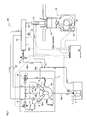
- Fig. 1 shows a constitutional example of an accumulator fuel injection device 50 used in a control of an internal combustion engine.
- the accumulator fuel injection device 50 is a device for injecting fuel to cylinders of a diesel engine 40 mounted on a vehicle and includes, as main components thereof, a fuel tank 1, a low pressure pump 2, a flow rate control valve 8, a high pressure pump 5, a common rail 10, a pressure control valve 12, fuel injection valves 13, a control device 60 and the like.
- a speed sensor 45 used for detecting an engine speed and a starter 44 for forcibly rotating a drive shaft at the time of starting are provided to the diesel engine 40.
- the low pressure pump 2 and pressurizing chambers 5a of the high pressure pump 5 are connected to each other through low pressure fuel passages 18a, 18b, the pressurizing chambers 5a of the high pressure pump 5 and the common rail 10 are connected to each other through a high pressure fuel passage 37, and the common rail 10 and the fuel injection valves 13 are connected to each other through a high pressure fuel passage 39. Further, return passages 30a to 30c for returning surplus fuel which is not injected from the fuel injection valves 13 to the fuel tank 1 are connected to the high pressure pump 5, the common rail 10, and the fuel injection valves 13 or the like.
- a flow rate control valve 8 is arranged in a middle portion of the low pressure fuel passage 18b in the high pressure pump 5.
- the flow rate control valve 8 for example, an electromagnetic proportional type flow rate control valve in which a stroke quantity of a valve element is variable corresponding to a supply current value so that an area of a fuel passing passage can be adjusted is used.
- the flow rate control valve 8 is used for adjusting a flow rate of fuel supplied to the pressurizing chambers 5a.
- the flow rate control valve 8 used in this embodiment is constituted as a normally open flow rate control valve where a flow passage of fuel is fully opened in a non-energizing state.
- the flow rate control valve 8 may be a normally closed flow rate control valve where a flow passage of fuel is fully closed in a non-energizing state.
- a pressure adjusting valve 14 which is arranged parallel to the flow rate control valve 8 is provided to a fuel passage branched from the low pressure fuel passage 18b on an upstream side of the flow rate control valve 8.
- the pressure adjusting valve 14 is connected to a return passage 30a communicating with the fuel tank 1.
- an overflow valve which is opened when the difference in pressure between in front of and behind the pressure adjusting valve 14, that is, the difference in pressure between the pressure in the low pressure fuel passage 18b and the pressure in the return passage 30a exceeds a predetermined value is used. Accordingly, in a state where fuel is supplied under pressure by the low pressure pump 2, the pressure in the low pressure fuel passages 18a, 18b is adjusted to a value larger than the pressure in the return passage 30a by predetermined difference in pressure.
- the low pressure pump 2 pumps up fuel in the fuel tank 1 and supplies fuel under pressure to the pressurizing chambers 5a of the high pressure pump 5 through the low pressure fuel passages 18a, 18b.
- the low pressure pump 2 shown in Fig. 1 is an in-tank electrically operated pump arranged in the inside of the fuel tank 1, and is driven with a voltage supplied from a battery so as to supply fuel under pressure.
- the low pressure pump 2 may be a pump which is arranged outside the fuel tank 1 or the low pressure pump 2 may be a gear pump driven using power of the diesel engine 40.
- the high pressure pump 5 pressurizes fuel introduced into the pressurizing chamber 5a by the low pressure pump 2 through a fuel intake valve 6 by a plunger 7, and supplies fuel in a high pressure state to the common rail 10 through a fuel discharge valve 9 and the high pressure fuel passage 37 under pressure.
- the fuel discharge valve 9 adopts the check valve structure where the higher a rail pressure on a discharge side becomes, the higher the sealing property is acquired.
- a cam 15 which drives the high pressure pump 5 is fixed to a cam shaft connected to a drive shaft of the diesel engine 40 by way of gears.
- the high pressure pump 5 shown in Fig. 1 includes two plungers 7. When these two plungers 7 are pushed up by the cam 15, fuel is pressurized in two pressurizing chambers 5a so that high pressure fuel is supplied under pressure to the common rail 10.
- the high pressure pump 5 of the accumulator fuel injection device 50 has the fuel lubrication type constitution where injection-use fuel is used as lubricant. That is, fuel supplied to the inside of the high pressure pump 5 through the low pressure fuel passage 18a temporarily flows into the cam chamber 16, and is supplied to the pressurizing chambers 5a from the cam chamber 16 through the low pressure fuel passage 18b.
- the common rail 10 accumulates high pressure fuel supplied under pressure from the high pressure pump 5, and supplies the high pressure fuel to plural fuel injection valves 13 connected to the common rail 10 through the high pressure fuel passages 39.
- the common rail 10 is provided with the pressure control valve 12 and a pressure sensor 21. Out of these parts, as the pressure sensor 21, a known pressure sensor such as a piezoelectric element sensor or a semiconductor sensor is used.
- the pressure control valve 12 for example, used is an electromagnetic proportional type control valve in which a stroke quantity of a valve element is variable corresponding to a supply current value so that an area of a fuel passing passage can be adjusted.
- a rail pressure is adjusted by controlling an energizing quantity to the pressure control valve 12 corresponding to a target rail pressure and a required injection quantity thus adjusting a flow rate of high pressure fuel discharged to a return passage 30b from the common rail 10.
- the pressure control valve 12 used in this embodiment is constituted of a normally open type pressure control valve where a fuel flow passage is fully opened in a non-energizing state.
- the pressure control valve 12 may be constituted of a normally closed type pressure control valve where the fuel flow passage is fully closed in a non-energizing state.
- the fuel injection valve 13 connected to the common rail 10 includes a nozzle body in which an injection hole is formed, and a nozzle needle which opens or closes the injection hole due to an advancing or retracting movement thereof.
- the fuel injection valve 13 is configured such that the injection hole is closed when a back pressure is applied to a rear end side of the nozzle needle as a load, while the injection hole is opened by releasing the applied back pressure thus injecting high pressure fuel supplied from the common rail 10 into the cylinder of the diesel engine.
- the fuel injection valve 13 can perform the normal fuel injection when the rail pressure assumes the predetermined injectable pressure or more.
- a piezoelectric injector which includes a piezoelectric element as a back pressure control means or a magnetic control type fuel injection valve which includes an electromagnetic solenoid as a back pressure control means is used.
- the piezoelectric injector is used as the fuel injection valve 13.
- the piezoelectric injector adopts the structure where fuel hardly leaks to a return passage 30c except for a passage for releasing a back pressure.
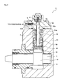
- Fig. 2 shows one example of the specific constitution of the high pressure pump 5.
- the high pressure pump 5 includes: a pump housing 51; a cylinder head 52 which is mounted in the inside of a circular columnar space 51a formed in the pump housing 51; the plunger 7 which is slidably held by a cylinder 52a of the cylinder head 52; a spring 55 which has both ends thereof engaged with the cylinder head 52 and a spring sheet 59 respectively and biases the plunger 7 downwardly; and a tappet structural body 58 which is interposed between the plunger 7 and the cam 15, and pushes up the plunger 7 while centering the plunger 7 along with the rotation of the cam 15.
- a fuel intake valve 6 is arranged on an upper opening portion of the cylinder 52a of the cylinder head 52, and the fuel discharge valve 9 is arranged in the lateral direction with respect to the axial direction of the cylinder 52a through a fuel discharge passage 52b.
- the flow rate control valve 8 and the pressure adjusting valve 14 provided to the high pressure pump 5 are not shown in the drawing.
- the high pressure pump 5 is configured such that after fuel supplied under pressure by the low pressure pump flows into the cam chamber 16, some of the fuel flows back and forth between the cam chamber 16 and the columnar space 51a. This fuel reaches a contact portion between a roller 54 of the tappet structural body 58 and the cam 15, a slide portion between the columnar space 51a and the tappet structural body 58, the above-mentioned slide portion between the cylinder 52a and the plunger 7, a slide portion between the cam shaft 11 and a bearing of the pump housing 51 or the like, and functions as a lubricant.
- Fig. 3 shows, in the control device 60 of the diesel engine 40 according to this embodiment, a constitutional example of a part relating to a control which is performed at the time of restarting the diesel engine 40 from an automatic stop state of the diesel engine 40 brought about by an idling stop control by functional blocks.
- the control device 60 includes: an idling stop control part 63 which includes an idling stop condition satisfaction detection part 61 and a restart condition satisfaction detection part 62; a target rail pressure calculation part 65; a rail pressure detection part 67; a rail pressure determination part 69; a fuel injection valve control part 71; a flow rate control valve control part 73; a pressure control valve control part 75; a starter control part 77 and the like.
- the control device 60 is mainly constituted of a microcomputer having the known constitution, and the respective parts are realized by executing programs using the microcomputer. Further, the control device 60 is provided with a storage means such as a RAM (Random Access Memory) not shown in the drawing for storing calculation results and detection results at the respective parts.
- a RAM Random Access Memory
- the idling stop control part 63 when the satisfaction of a predetermined idling stop condition is detected by the idling stop condition satisfaction detection part 61, transmits an instruction to stop the diesel engine 40 by stopping the fuel injection to the fuel injection valve control part 71.
- the idling stop control part 63 transmits an instruction to interrupt the energizing of the flow rate control valve 8 to the flow rate control valve control part 73.
- the idling stop control part 63 for holding a rail pressure at a predetermined pressure, transmits an instruction to energize the pressure control valve 12 at a predetermined holding current A1 to the pressure control valve control part 75.
- the idling stop control part 63 when the satisfaction of a predetermined restarting condition is detected by the restarting condition satisfaction detection part 62 during a period where the diesel engine 40 is automatically stopped by the idling stop control, transmits an instruction to restart the diesel engine 40 by restarting the fuel injection to the fuel injection valve control part 71 and the starter control part 77. Further, the idling stop control part 63 transmits the satisfaction of the restarting condition to the rail pressure determination part 69 when the restarting condition is satisfied.
- the idling stop condition detected by the idling stop condition satisfaction detection part 61 may be set such that the idling stop condition includes at least one of, for example, a condition that an engine switch Sw is in an ON state, a condition that a gear sensor indicates a neutral position as a detection position Sg, a condition that a brake pedal sensor indicates that a detection position Sb is in a pedal stepped-in state, a condition that an engine speed Ne of the diesel engine 40 is equal to or less than a predetermined threshold value, and a condition that a state where a vehicle speed V is 0 continues for a predetermined time or more and the like.
- the idling stop condition is not limited to these conditions.
- the restarting condition detected by the restart condition satisfaction detection part 62 may be set such that the restart condition includes some conditions out of conditions such as a condition that the detection position Sg of the gear sensor is released from a neutral state during an automatic stop of the diesel engine 40, and a condition that an acceleration pedal Acc is stepped in during the automatic stop of the diesel engine 40.
- the restart condition is not limited to these conditions.
- the fuel injection valve control part 71 calculates a target fuel injection quantity Qtgt based on an engine speed Ne, an acceleration operation quantity Acc or the like, and also generates a control signal for the fuel injection valve 13 corresponding to the target fuel injection quantity Qtgt, and outputs the control signal to the fuel injection valve 13.
- a signal indicative of the satisfaction of an idling stop condition is transmitted to the fuel injection valve control part 71 from the idling stop control part 63
- the fuel injection valve control part 71 stops the fuel injection, and restarts the fuel injection when a signal indicative of the satisfaction of a restarting condition is transmitted to the fuel injection valve control part.
- the fuel injection valve control part 71 of the control device 60 is configured not to restart the fuel injection control until the fuel injection valve control part 71 receives a start permission instruction from the rail pressure determination part 69 even when the satisfaction of a restart condition is transmitted to the fuel injection valve control part 71 after the diesel engine 40 is automatically stopped by an idling stop control.
- the starter control part 77 performs a control where the starter 44 is operated at the time of starting the diesel engine 40 so that a drive shaft is forcibly rotated whereby the inside of the cylinder is brought into a compression state.
- the starter control part 77 of the control device 60 is configured not to operate the starter 44 until the starter control part 77 receives a start permission instruction from the rail pressure determination part 69 even when the satisfaction of the restart condition is transmitted to the starter control part 77 after the diesel engine 40 is automatically stopped by an idling stop control.
- the target rail pressure calculation part 65 calculates a target rail pressure Ptgt based on an engine speed Ne, an acceleration operation quantity Acc or the like, and stores the calculated target rail pressure Ptgt in the storage means. Further, the rail pressure detection part 67 continuously reads a sensor value of the pressure sensor 21 provided to the common rail 10, acquires a detected rail pressure Psensor and stores the acquired detected rail pressure Psensor in the storage means.
- the rail pressure determination part 69 when the satisfaction of a restarting condition is transmitted from the restarting condition satisfaction detection part 62, continuously reads a detected rail pressure Psensor and determines whether or not the detected rail pressure Psensor is equal to or more than a predetermined threshold value Prail_thr1.
- the threshold value Prail_thr1 is set to a value which prevents a load applied to a driving system of the high pressure pump 5 from being increased even when driving of the high pressure pump 5 is started.
- the rail pressure determination part 69 when the detected rail pressure Psensor is equal to or more than the threshold value Prail_thr1, transmits an instruction signal for opening the pressure control valve 12 to the pressure control valve control part 75. Further, the rail pressure determination part 69 is configured to transmit a start permission instruction to the fuel injection valve control part 71 and the starter control part 77 when the detected rail pressure Psensor takes a value less than the threshold value Prail_thr1.
- the flow rate control valve control part 73 and the pressure control valve control part 75 execute, basically, an energization control of the flow rate control valve 8 and the pressure control valve 12 respectively so that a detected rail pressure Psensor becomes a target rail pressure Ptgt.
- the flow rate control valve control part 73 controls a flow rate of fuel to be supplied to the pressurizing chamber 5a of the high pressure pump 5 by adjusting opening of the flow rate control valve 8 so that a flow rate of high pressure fuel supplied under pressure to the common rail 10 from the high pressure pump 5 is changed whereby a rail pressure is adjusted.
- the pressure control valve control part 75 controls a flow rate of return fuel discharged to the return passage 30b from the common rail 10 by adjusting opening of the pressure control valve 12 thus adjusting a rail pressure.
- Whether a control of a rail pressure is performed by the flow rate control valve control part 73, by the pressure control valve control part 75 or by both the flow rate control valve control part 73 and the pressure control valve control part 75 is determined depending on a traveling state of the vehicle and an operation state of the diesel engine 40. However, at the time of starting the diesel engine 40, the control of the rail pressure is not performed until the engine speed Ne detected by the speed sensor 45 reaches a predetermined engine speed NeO, and the flow rate control valve 8 is basically held in a fully opened state and the pressure control valve 12 is basically closed.
- the flow rate control valve control part 73 interrupts the energizing of the flow rate control valve 8 when a signal indicating the satisfaction of an idling stop condition is transmitted to the flow rate control valve control part 73 from the idling stop control part 63. Since the flow rate control valve 8 of this embodiment has the normally-open constitution, when the energizing is interrupted at the moment the diesel engine 40 is automatically stopped, the flow rate control valve 8 is fully closed.
- the pressure control valve control part 75 receives an instruction of a control to be performed accompanying with the satisfaction of an idling stop condition from the idling stop control part 63, the pressure control valve control part 75 performs a control of continuously supplying a predetermined holding current A1 to the pressure control valve 12.
- This holding current A1 is a control value by which a rail pressure is adjusted to a value larger than the injectable pressure, and is set to a value by which the rail pressure at the time of restarting the engine which is equal to or more than the injectable pressure is ensured even when the diesel engine 40 is automatically stopped for a relatively long time.
- the pressure control valve control part 75 when a rail pressure assumes a threshold value Prail_thr1 or more when a restarting condition of the diesel engine 40 is satisfied and the pressure control valve control part 75 receives an instruction to open the pressure control valve 12 outputted from the rail pressure determination part 69, performs a control of changing over a current value of an electric current supplied to the pressure control valve 12 from a holding current A1 to a valve opening current A2.
- This valve opening current A2 is set in advance to a current value by which the rail pressure becomes less than the threshold value Prail_thr1 and is equal to or more than the injectable pressure.
- a valve opening current A2 is supplied to the pressure control valve 12 in a state where the rail pressure is threshold value Prail_thr1 or more, the pressure control valve 12 is opened so that the rail pressure is lowered to become lower than the threshold value Prail_thr1. That is, although the pressure control valve 12 is basically closed at the time of restarting the diesel engine 40, a valve opening current A2 is supplied to the pressure control valve 12 when the detected rail pressure Psensor at the time of satisfying a restarting condition assumes a threshold value Prail_thr1 or more so that the pressure control valve 12 is opened.
- valve opening current A2 is set to the current value by which the rail pressure becomes less than the threshold value Prail_thr1 and becomes equal to or more than the injectable pressure and hence, even when the rail pressure is lowered to a value less than the threshold value Prail_thr1, the restartability of the diesel engine 40 is not influenced by such lowering of the rail pressure.
- valve opening current A2 supplied to the pressure control valve 12 Besides setting the valve opening current A2 supplied to the pressure control valve 12 to a fixed value in advance, for example, when a detected rail pressure Psensor immediately before the diesel engine 40 is automatically stopped by an idling stop control takes a value less than the threshold value Prail_thr1, a current value of an electric current supplied to the pressure control valve 12 in such a state may be also set as the valve opening current A2.
- a current value of an electric current supplied to the pressure control valve 12 in such a state may be also set as the valve opening current A2.
- step S11 after starting the control, it is determined whether or not a predetermined idling stop condition is satisfied (period from t0 to t1 in Fig. 4 ).
- a predetermined idling stop condition is satisfied, the processing advances to step S12 where the fuel injection by the fuel injection valve 13 is stopped so that the diesel engine 40 is stopped, and the supply of a holding current A1 to the pressure control valve 12 is started in step S13 (t1 in Fig. 4 ).
- step S14 it is determined whether or not a predetermined restarting condition is satisfied in step S14.
- This step S14 is repeated until the restarting condition is satisfied (period from t1 to t2 in Fig. 4 ), and when the restarting condition is satisfied, the processing advances to step S15.
- step S15 a detected rail pressure Psensor is read, and it is also determined whether or not the detected rail pressure Psensor is equal to or more than a threshold value Prail_thr1 (t2 in Fig. 4 ).
- a threshold value Prail_thr1 t2 in Fig. 4
- the processing advances to step S18 where the starter 44 is operated in such a state and the fuel injection from the fuel injection valve 13 is started so that the diesel engine 40 is restarted.
- step S15 when it is determined that the detected rail pressure Psensor is equal to or more than the threshold value Prail_thr1 in step S15, the processing advances to step S16 where an electric current supplied to the pressure control valve 12 is changed over to a valve opening current A2 from the holding current A1. Due to such an operation, the pressure control valve 12 is opened so that the lowering of the rail pressure is started along with such valve opening.
- the detected rail pressure Psensor is continuously read, and it is determined whether or not the detected rail pressure Psensor takes a value less than the threshold value Prail_thr1 in step S17 until the detected rail pressure Psensor becomes less than the threshold value Prail_thr1 (period from t2 to t3 in Fig. 4 ).
- the processing advances to step S18 where the starter 44 is operated and the fuel injection from the fuel injection valve 13 is started so that the diesel engine 40 is restarted (t3 in Fig. 4 ).
- step S19 After the diesel engine 40 is restarted, it is determined whether or not an engine speed Ne reaches a predetermined engine speed NeO in step S19 (period from t3 to t4 in Fig. 4 ).
- the processing advances to step S20 so that the control of the diesel engine 40 is shifted to a rail pressure control mode (t4 in Fig. 4 ).
- the explanation has been made with respect to the example which uses the accumulator fuel injection device 50 having the constitution where a leak passage for fuel other than fuel used for a back pressure control is not provided to the fuel injection valve so that a rail pressure is hardly lowered at the time of automatically stopping the diesel engine 40.
- the present invention is not limited to the case which uses such an accumulator fuel injection device 50.
- a control device of the internal combustion engine according to the present invention is configured to perform a control of opening a pressure control valve before a restarting condition of the internal combustion engine is satisfied.
- the control device for an internal combustion engine and a method of controlling the internal combustion engine according to this embodiment are explained by focusing on a point by which the control device for an internal combustion engine and the method of controlling the internal combustion engine according to this embodiment differ from the control device for an internal combustion engine and the method of controlling the internal combustion engine according to the device described above.
- a control device for a diesel engine 40 according to this embodiment basically has the substantially same constitution as the control device 60 for an internal combustion engine according to the device described above. However, in the control device for a diesel engine 40 according to this embodiment, a function of opening a pressure control valve in advance by determining that a restarting condition will be satisfied in a short time at the time of automatically stopping the diesel engine 40 by an idling stop control is added to a restarting condition satisfaction detection part and a rail pressure determination part.
- the restarting condition satisfaction detection part basically has substantially same function as the restarting condition satisfaction detection part of the control device according to the device described above. Further, the restarting condition satisfaction detection part is configured to determine that a restarting condition will be satisfied in a short time when some of the plural restarting conditions are satisfied and to transmit a restarting condition satisfying preliminary signal to a rail pressure determination part.
- the restarting condition satisfaction detection part detects information based on which it can be determined that such a restarting condition will be satisfied in a short time
- the restarting condition satisfaction detection part transmits a restarting condition satisfying preliminary signal to the rail pressure determination part.
- Information for determining that the restarting condition will be satisfied in a short time is not limited to information used in the above-mentioned example.
- the rail pressure determination part determines whether or not the detected rail pressure Psensor is equal to or more than a predetermined threshold value Prail_thr1.
- the rail pressure determination part transmits an instruction to open a pressure control valve 12 to a pressure control valve control part 75.
- the pressure control valve 12 is opened before the satisfaction of the restarting condition so that the lowering of the rail pressure is started along with such valve opening.
- the rail pressure becomes less than the threshold value Prail_thr1 at the time of satisfaction of the restarting condition, or even when the rail pressure is equal to or more than the threshold value Prail_thr1 at the time of satisfaction of the restarting condition, thereafter, time necessary for the rail pressure to become the threshold value Prail_thr1 is shortened so that a time before restarting can be shortened.
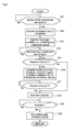
- step S51 after starting the control, it is determined whether or not a predetermined idling stop condition is satisfied (period from t0 to t1 in Fig. 6 ).
- a predetermined idling stop condition is satisfied, the processing advances to step S52 where the fuel injection by the fuel injection valve 13 is stopped so that the diesel engine 40 is stopped, and the supply of a holding current A1 to the pressure control valve 12 is started in step S53 (t1 in Fig. 6 ).
- step S54 it is determined whether or not the diesel engine 40 will be restarted in a short time in step S54. This step S54 is repeated until a restarting condition satisfying preliminary signal is detected (period from t1 to t2 in Fig. 6 ), and when it is determined that the diesel engine 40 will be restarted in a short time, the processing advances to step S55.
- step S55 a detected rail pressure Psensor is read, and it is also determined whether or not the detected rail pressure Psensor is equal to or more than a threshold value Prail_thr1 (t2 in Fig. 6 ).
- a threshold value Prail_thr1 t2 in Fig. 6
- the processing directly advances to step S57.
- step S56 an electric current supplied to the pressure control valve 12 is changed over to a valve opening current A2 from the holding current A1 and, thereafter, the processing advances to step S57. Due to the supply of the valve opening current A2 to the pressure control valve 12, the pressure control valve 12 is opened so that the lowering of the rail pressure is started along with such valve opening.
- step S57 the determination on whether or not the restarting condition is satisfied is repeated until the restarting condition is satisfied (period from t2 to t3 in Fig. 6 ).
- the processing advances to step S58, and it is determined whether or not the detected rail pressure Psensor takes a value less than the threshold value Prail_thr1 (t3 in Fig. 6 ).
- the processing advances to step S59 where a starter 44 is operated and the fuel injection from the fuel injection valve 13 is started thus restarting the diesel engine 40 (t4 in Fig. 6 ).
- this step S58 is repeated until the detected rail pressure Psensor becomes less than the threshold value Prail_thr1 (period from t3 to t4 in Fig. 6 ).
- step S60 After the diesel engine 40 is restarted, it is determined whether or not an engine speed Ne reaches a predetermined engine speed NeO in step S60 (period from t4 to t5 in Fig. 6 ).
- the processing advances to step S61 so that the control of the diesel engine 40 is shifted to a rail pressure control mode (point of time t5 in Fig. 6 ).
- the rail pressure can be lowered during a period before the restarting condition is satisfied. Accordingly, a time from a point of time that the restarting condition is satisfied to a point of time that restarting is allowed can be shortened so that restartability of the diesel engine 40 can be enhanced. Further, when the fuel injection from the fuel injection valve 13 is started so that driving of the high pressure pump 5 is started, a state where the rail pressure is lowered is brought about. Accordingly, there is no possibility that the pressure in the pressurizing chamber 5a is remarkably increased and hence, a large force for elevating a plunger 7 becomes unnecessary.
Landscapes
- Engineering & Computer Science (AREA)
- Chemical & Material Sciences (AREA)
- Combustion & Propulsion (AREA)
- Mechanical Engineering (AREA)
- General Engineering & Computer Science (AREA)
- Electrical Control Of Air Or Fuel Supplied To Internal-Combustion Engine (AREA)
- Fuel-Injection Apparatus (AREA)
- Control Of Vehicle Engines Or Engines For Specific Uses (AREA)
Claims (3)
- Steuervorrichtung (60) für eine Brennkraftmaschine (40), die eine Steuervorrichtung (60) zum Ausführen einer Steuerung der Brennkraftmaschine (40) durch eine Druckspeicher-Kraftstoffeinspritzvorrichtung (50) ist, wobei die Steuervorrichtung (60) umfasst: eine gemeinsame Verteilerleitung (10), mit der ein Kraftstoffeinspritzventil (13) verbunden ist; eine Hochdruckpumpe (5), die der gemeinsamen Verteilerleitung (10) Kraftstoff unter Druck zuführt; und ein Drucksteuerventil (12), das eine Durchflussmenge von Kraftstoff, der von der gemeinsamen Verteilerleitung (10) ausgegeben wird, einstellt, wobei die Steuervorrichtung (60) der Brennkraftmaschine (40) eine Leerlaufstopp-Steuerung ausführen kann, wobei die Steuervorrichtung (60) Folgendes umfasst:einen Leerlaufstoppbedingung-erfüllt-Detektionsabschnitt (61), der detektiert, dass eine vorgegebene Leerlaufstoppbedingung erfüllt ist, und einen Befehl ausgibt, um die Brennkraftmaschine (40) automatisch zu stoppen;einen Neustartbedingung-erfüllt-Detektionsabschnitt (62), der während eines automatischen Stopps der Brennkraftmaschine (40) detektiert, dass eine vorgegebene Neustartbedingung erfüllt ist, und einen Befehl ausgibt, um die Brennkraftmaschine (40) neu zu starten;einen Verteilerleitungsdruck-Detektionsabschnitt (67), der den Druck in der gemeinsamen Verteilerleitung (10) detektiert;dadurch gekennzeichnet, dass der Neustartbedingung-erfüllt-Detektionsabschnitt (62) detektiert, dass die Neustartbedingung in kurzer Zeit erfüllt sein wird, und die Steuervorrichtung ferner umfasst: einen Drucksteuerventil-Steuerabschnitt (75), der das Drucksteuerventil (12) vor dem erneuten Starten der Brennkraftmaschine (40) öffnet, wenn der Druck in der gemeinsamen Verteilerleitung (10) zu der kurzen Zeit vor der Erfüllung der Neustartbedingung gleich oder größer als ein vorgegebener Schwellenwert wird, und der Drucksteuerventil-Steuerabschnitt (75) das Drucksteuerventil (12) öffnet, wenn detektiert wird, dass die Neustartbedingung in kurzer Zeit erfüllt sein wird und der Druck in der gemeinsamen Verteilerleitung (10) den Schwellenort oder einen Wert darüber annimmt.
- Steuervorrichtung (60) für eine Brennkraftmaschine (40) nach Anspruch 1, wobei der Schwellenwert ein Wert ist, der anhand einer Last eingestellt wird, die an ein Antriebssystem der Hochdruckpumpe (5) von der Hochdruckpumpe (5) angelegt werden darf.
- Steuervorrichtung (60) für eine Brennkraftmaschine (40) nach einem der Ansprüche 1 bis 2, wobei die Steuervorrichtung (60) einen Verteilerleitungsdruck-Bestimmungsabschnitt (69) umfasst, der die Brennkraftmaschine (40) neu startet, wenn der Druck in der gemeinsamen Verteilerleitung (10) kleiner als der Schwellenwert wird, nachdem die Neustartbedingung erfüllt ist.
Applications Claiming Priority (2)
| Application Number | Priority Date | Filing Date | Title |
|---|---|---|---|
| JP2009244399 | 2009-10-23 | ||
| PCT/JP2010/054317 WO2011048827A1 (ja) | 2009-10-23 | 2010-03-15 | 内燃機関の制御装置 |
Publications (3)
| Publication Number | Publication Date |
|---|---|
| EP2492480A1 EP2492480A1 (de) | 2012-08-29 |
| EP2492480A4 EP2492480A4 (de) | 2014-01-01 |
| EP2492480B1 true EP2492480B1 (de) | 2015-11-25 |
Family
ID=43900071
Family Applications (1)
| Application Number | Title | Priority Date | Filing Date |
|---|---|---|---|
| EP10824679.4A Not-in-force EP2492480B1 (de) | 2009-10-23 | 2010-03-15 | Steuerungsvorrichtung für einen verbrennungsmotor |
Country Status (3)
| Country | Link |
|---|---|
| EP (1) | EP2492480B1 (de) |
| JP (1) | JP5314156B2 (de) |
| WO (1) | WO2011048827A1 (de) |
Families Citing this family (7)
| Publication number | Priority date | Publication date | Assignee | Title |
|---|---|---|---|---|
| JP5131265B2 (ja) * | 2009-12-24 | 2013-01-30 | 株式会社デンソー | 燃料圧力制御装置 |
| DE102010043439A1 (de) * | 2010-11-05 | 2012-05-10 | Robert Bosch Gmbh | Kraftstoffeinspritzsystem einer Brennkraftmaschine |
| JP2012237224A (ja) * | 2011-05-11 | 2012-12-06 | Bosch Corp | 蓄圧式燃料噴射装置の制御装置及び制御方法並びに蓄圧式燃料噴射装置 |
| US9353699B2 (en) * | 2014-03-31 | 2016-05-31 | Ford Global Technologies, Llc | Rapid zero flow lubrication methods for a high pressure pump |
| DE102015203348B3 (de) * | 2015-02-25 | 2016-02-18 | Ford Global Technologies, Llc | Verfahren zum Betrieb einer Common-Rail-Einspritzanordnung für eine Brennkraftmaschine mit Stopp-Start-System |
| DE102015220098B3 (de) * | 2015-10-15 | 2017-02-16 | Continental Automotive Gmbh | Verfahren und Vorrichtung zum Betreiben einer Brennkraftmaschine mit einem Hochdruck-Kraftstoffeinspritzsystem |
| JP7226173B2 (ja) * | 2019-07-30 | 2023-02-21 | 株式会社デンソー | 燃料噴射システムの制御装置 |
Family Cites Families (16)
| Publication number | Priority date | Publication date | Assignee | Title |
|---|---|---|---|---|
| JP3317202B2 (ja) * | 1997-08-04 | 2002-08-26 | トヨタ自動車株式会社 | 蓄圧式エンジンの燃料噴射制御装置 |
| GB2332241B (en) * | 1997-12-11 | 2001-12-19 | Denso Corp | Accumulator fuel injection system for diesel engine of automotive vehicles |
| JP2000136763A (ja) * | 1998-11-04 | 2000-05-16 | Unisia Jecs Corp | 燃料噴射制御装置 |
| JP4635351B2 (ja) * | 2001-02-28 | 2011-02-23 | トヨタ自動車株式会社 | 内燃機関の燃料供給制御装置 |
| JP2004324440A (ja) * | 2003-04-22 | 2004-11-18 | Toyota Motor Corp | ディーゼルエンジン制御装置 |
| JP2005147019A (ja) * | 2003-11-17 | 2005-06-09 | Mitsubishi Electric Corp | 筒内噴射型内燃機関の燃圧制御装置 |
| JP2006022649A (ja) * | 2004-07-06 | 2006-01-26 | Bosch Corp | ディーゼルエンジンの液化ガス燃料供給装置 |
| JP4211733B2 (ja) * | 2004-12-08 | 2009-01-21 | 株式会社デンソー | コモンレール式燃料噴射装置 |
| JP2007092717A (ja) * | 2005-09-30 | 2007-04-12 | Toyota Motor Corp | 内燃機関用燃料供給装置 |
| JP2008163796A (ja) | 2006-12-27 | 2008-07-17 | Mitsubishi Fuso Truck & Bus Corp | 内燃機関の制御装置 |
| DE102007035824A1 (de) * | 2007-07-31 | 2009-02-05 | Robert Bosch Gmbh | Druckhaltefunktion bei Vollhybridantrieb |
| JP2009079514A (ja) * | 2007-09-26 | 2009-04-16 | Denso Corp | 筒内噴射式内燃機関の燃圧制御装置 |
| JP2009079564A (ja) * | 2007-09-27 | 2009-04-16 | Denso Corp | 内燃機関の高圧ポンプ制御装置 |
| FR2924177A3 (fr) * | 2007-11-26 | 2009-05-29 | Renault Sas | Procede et dispositif d'amelioration du demarrage direct d'un moteur a combustion interne equipe d'un systeme de "stop&start" |
| JP2010261335A (ja) * | 2009-04-30 | 2010-11-18 | Hitachi Automotive Systems Ltd | 筒内噴射式エンジンの制御装置 |
| JP5131265B2 (ja) * | 2009-12-24 | 2013-01-30 | 株式会社デンソー | 燃料圧力制御装置 |
-
2010
- 2010-03-15 EP EP10824679.4A patent/EP2492480B1/de not_active Not-in-force
- 2010-03-15 WO PCT/JP2010/054317 patent/WO2011048827A1/ja not_active Ceased
- 2010-03-15 JP JP2011537150A patent/JP5314156B2/ja not_active Expired - Fee Related
Also Published As
| Publication number | Publication date |
|---|---|
| JP5314156B2 (ja) | 2013-10-16 |
| WO2011048827A1 (ja) | 2011-04-28 |
| JPWO2011048827A1 (ja) | 2013-03-07 |
| EP2492480A1 (de) | 2012-08-29 |
| EP2492480A4 (de) | 2014-01-01 |
Similar Documents
| Publication | Publication Date | Title |
|---|---|---|
| EP2492480B1 (de) | Steuerungsvorrichtung für einen verbrennungsmotor | |
| JP5387538B2 (ja) | 筒内噴射式内燃機関のフェールセーフ制御装置 | |
| US7801672B2 (en) | After-stop fuel pressure control device of direct injection engine | |
| KR101175123B1 (ko) | 내연 기관의 연료 공급 장치 및 연료 공급 장치의 제어 장치 | |
| JP4355346B2 (ja) | 内燃機関の制御装置 | |
| JP5131265B2 (ja) | 燃料圧力制御装置 | |
| US9410498B2 (en) | Method and device for operating a high-pressure accumulator fuel injection system for an internal combustion engine | |
| JP4045594B2 (ja) | 蓄圧式燃料噴射装置 | |
| JP2009079514A (ja) | 筒内噴射式内燃機関の燃圧制御装置 | |
| JP2011127523A (ja) | 蓄圧式燃料噴射装置の制御装置及び制御方法並びに蓄圧式燃料噴射装置 | |
| JP5464649B2 (ja) | 内燃機関の制御装置 | |
| EP1321664B1 (de) | Kraftstoffeinspritzsystem mit einer Vorrichtung zum Entlüften von Kraftstoff | |
| JP3191388B2 (ja) | ディーゼル機関の蓄圧式燃料供給装置 | |
| JP2011064108A (ja) | 燃料噴射装置 | |
| JP3982516B2 (ja) | 内燃機関用燃料噴射装置 | |
| JP4509191B2 (ja) | 筒内噴射エンジンの燃料噴射制御装置 | |
| JP5140191B2 (ja) | ディーゼルエンジンの制御装置 | |
| JP4635351B2 (ja) | 内燃機関の燃料供給制御装置 | |
| JP5477899B2 (ja) | 蓄圧式燃料噴射装置の制御装置及び制御方法並びに蓄圧式燃料噴射装置 | |
| JP5382870B2 (ja) | 蓄圧式燃料噴射装置の制御装置及び制御方法並びに蓄圧式燃料噴射装置 | |
| JP2012145023A (ja) | 内燃機関の高圧燃料供給装置 | |
| JPH0730732B2 (ja) | 蓄圧式燃料供給装置 | |
| JPH11125140A (ja) | 内燃機関の蓄圧式燃料供給装置 | |
| JP4321495B2 (ja) | 蓄圧式燃料噴射装置 | |
| JP2012237224A (ja) | 蓄圧式燃料噴射装置の制御装置及び制御方法並びに蓄圧式燃料噴射装置 |
Legal Events
| Date | Code | Title | Description |
|---|---|---|---|
| PUAI | Public reference made under article 153(3) epc to a published international application that has entered the european phase |
Free format text: ORIGINAL CODE: 0009012 |
|
| 17P | Request for examination filed |
Effective date: 20120523 |
|
| AK | Designated contracting states |
Kind code of ref document: A1 Designated state(s): AT BE BG CH CY CZ DE DK EE ES FI FR GB GR HR HU IE IS IT LI LT LU LV MC MK MT NL NO PL PT RO SE SI SK SM TR |
|
| DAX | Request for extension of the european patent (deleted) | ||
| A4 | Supplementary search report drawn up and despatched |
Effective date: 20131204 |
|
| RIC1 | Information provided on ipc code assigned before grant |
Ipc: F02M 63/02 20060101ALI20131128BHEP Ipc: F02M 37/00 20060101ALI20131128BHEP Ipc: F02D 41/38 20060101ALI20131128BHEP Ipc: F02D 41/06 20060101AFI20131128BHEP Ipc: F02M 51/00 20060101ALI20131128BHEP |
|
| 17Q | First examination report despatched |
Effective date: 20150120 |
|
| REG | Reference to a national code |
Ref country code: DE Ref legal event code: R079 Ref document number: 602010029274 Country of ref document: DE Free format text: PREVIOUS MAIN CLASS: F02D0041220000 Ipc: F02D0041060000 |
|
| GRAP | Despatch of communication of intention to grant a patent |
Free format text: ORIGINAL CODE: EPIDOSNIGR1 |
|
| RIC1 | Information provided on ipc code assigned before grant |
Ipc: F02D 41/38 20060101ALI20150715BHEP Ipc: F02M 63/02 20060101ALI20150715BHEP Ipc: F02M 37/00 20060101ALI20150715BHEP Ipc: F02N 11/08 20060101ALN20150715BHEP Ipc: F02D 41/04 20060101ALN20150715BHEP Ipc: F02M 51/00 20060101ALI20150715BHEP Ipc: F02D 41/06 20060101AFI20150715BHEP |
|
| INTG | Intention to grant announced |
Effective date: 20150817 |
|
| GRAS | Grant fee paid |
Free format text: ORIGINAL CODE: EPIDOSNIGR3 |
|
| GRAA | (expected) grant |
Free format text: ORIGINAL CODE: 0009210 |
|
| AK | Designated contracting states |
Kind code of ref document: B1 Designated state(s): AT BE BG CH CY CZ DE DK EE ES FI FR GB GR HR HU IE IS IT LI LT LU LV MC MK MT NL NO PL PT RO SE SI SK SM TR |
|
| REG | Reference to a national code |
Ref country code: GB Ref legal event code: FG4D |
|
| REG | Reference to a national code |
Ref country code: CH Ref legal event code: EP |
|
| REG | Reference to a national code |
Ref country code: AT Ref legal event code: REF Ref document number: 762753 Country of ref document: AT Kind code of ref document: T Effective date: 20151215 |
|
| REG | Reference to a national code |
Ref country code: IE Ref legal event code: FG4D |
|
| REG | Reference to a national code |
Ref country code: DE Ref legal event code: R096 Ref document number: 602010029274 Country of ref document: DE |
|
| REG | Reference to a national code |
Ref country code: FR Ref legal event code: PLFP Year of fee payment: 7 |
|
| REG | Reference to a national code |
Ref country code: LT Ref legal event code: MG4D |
|
| REG | Reference to a national code |
Ref country code: NL Ref legal event code: MP Effective date: 20160225 |
|
| REG | Reference to a national code |
Ref country code: AT Ref legal event code: MK05 Ref document number: 762753 Country of ref document: AT Kind code of ref document: T Effective date: 20151125 |
|
| PG25 | Lapsed in a contracting state [announced via postgrant information from national office to epo] |
Ref country code: NO Free format text: LAPSE BECAUSE OF FAILURE TO SUBMIT A TRANSLATION OF THE DESCRIPTION OR TO PAY THE FEE WITHIN THE PRESCRIBED TIME-LIMIT Effective date: 20160225 Ref country code: HR Free format text: LAPSE BECAUSE OF FAILURE TO SUBMIT A TRANSLATION OF THE DESCRIPTION OR TO PAY THE FEE WITHIN THE PRESCRIBED TIME-LIMIT Effective date: 20151125 Ref country code: ES Free format text: LAPSE BECAUSE OF FAILURE TO SUBMIT A TRANSLATION OF THE DESCRIPTION OR TO PAY THE FEE WITHIN THE PRESCRIBED TIME-LIMIT Effective date: 20151125 Ref country code: LT Free format text: LAPSE BECAUSE OF FAILURE TO SUBMIT A TRANSLATION OF THE DESCRIPTION OR TO PAY THE FEE WITHIN THE PRESCRIBED TIME-LIMIT Effective date: 20151125 Ref country code: NL Free format text: LAPSE BECAUSE OF FAILURE TO SUBMIT A TRANSLATION OF THE DESCRIPTION OR TO PAY THE FEE WITHIN THE PRESCRIBED TIME-LIMIT Effective date: 20151125 Ref country code: IS Free format text: LAPSE BECAUSE OF FAILURE TO SUBMIT A TRANSLATION OF THE DESCRIPTION OR TO PAY THE FEE WITHIN THE PRESCRIBED TIME-LIMIT Effective date: 20160325 |
|
| PG25 | Lapsed in a contracting state [announced via postgrant information from national office to epo] |
Ref country code: SE Free format text: LAPSE BECAUSE OF FAILURE TO SUBMIT A TRANSLATION OF THE DESCRIPTION OR TO PAY THE FEE WITHIN THE PRESCRIBED TIME-LIMIT Effective date: 20151125 Ref country code: PL Free format text: LAPSE BECAUSE OF FAILURE TO SUBMIT A TRANSLATION OF THE DESCRIPTION OR TO PAY THE FEE WITHIN THE PRESCRIBED TIME-LIMIT Effective date: 20151125 Ref country code: FI Free format text: LAPSE BECAUSE OF FAILURE TO SUBMIT A TRANSLATION OF THE DESCRIPTION OR TO PAY THE FEE WITHIN THE PRESCRIBED TIME-LIMIT Effective date: 20151125 Ref country code: PT Free format text: LAPSE BECAUSE OF FAILURE TO SUBMIT A TRANSLATION OF THE DESCRIPTION OR TO PAY THE FEE WITHIN THE PRESCRIBED TIME-LIMIT Effective date: 20160325 Ref country code: LV Free format text: LAPSE BECAUSE OF FAILURE TO SUBMIT A TRANSLATION OF THE DESCRIPTION OR TO PAY THE FEE WITHIN THE PRESCRIBED TIME-LIMIT Effective date: 20151125 Ref country code: AT Free format text: LAPSE BECAUSE OF FAILURE TO SUBMIT A TRANSLATION OF THE DESCRIPTION OR TO PAY THE FEE WITHIN THE PRESCRIBED TIME-LIMIT Effective date: 20151125 Ref country code: GR Free format text: LAPSE BECAUSE OF FAILURE TO SUBMIT A TRANSLATION OF THE DESCRIPTION OR TO PAY THE FEE WITHIN THE PRESCRIBED TIME-LIMIT Effective date: 20160226 |
|
| PG25 | Lapsed in a contracting state [announced via postgrant information from national office to epo] |
Ref country code: CZ Free format text: LAPSE BECAUSE OF FAILURE TO SUBMIT A TRANSLATION OF THE DESCRIPTION OR TO PAY THE FEE WITHIN THE PRESCRIBED TIME-LIMIT Effective date: 20151125 Ref country code: IT Free format text: LAPSE BECAUSE OF FAILURE TO SUBMIT A TRANSLATION OF THE DESCRIPTION OR TO PAY THE FEE WITHIN THE PRESCRIBED TIME-LIMIT Effective date: 20151125 |
|
| REG | Reference to a national code |
Ref country code: DE Ref legal event code: R097 Ref document number: 602010029274 Country of ref document: DE |
|
| PG25 | Lapsed in a contracting state [announced via postgrant information from national office to epo] |
Ref country code: RO Free format text: LAPSE BECAUSE OF FAILURE TO SUBMIT A TRANSLATION OF THE DESCRIPTION OR TO PAY THE FEE WITHIN THE PRESCRIBED TIME-LIMIT Effective date: 20151125 Ref country code: BE Free format text: LAPSE BECAUSE OF NON-PAYMENT OF DUE FEES Effective date: 20160331 Ref country code: EE Free format text: LAPSE BECAUSE OF FAILURE TO SUBMIT A TRANSLATION OF THE DESCRIPTION OR TO PAY THE FEE WITHIN THE PRESCRIBED TIME-LIMIT Effective date: 20151125 Ref country code: SM Free format text: LAPSE BECAUSE OF FAILURE TO SUBMIT A TRANSLATION OF THE DESCRIPTION OR TO PAY THE FEE WITHIN THE PRESCRIBED TIME-LIMIT Effective date: 20151125 Ref country code: SK Free format text: LAPSE BECAUSE OF FAILURE TO SUBMIT A TRANSLATION OF THE DESCRIPTION OR TO PAY THE FEE WITHIN THE PRESCRIBED TIME-LIMIT Effective date: 20151125 Ref country code: DK Free format text: LAPSE BECAUSE OF FAILURE TO SUBMIT A TRANSLATION OF THE DESCRIPTION OR TO PAY THE FEE WITHIN THE PRESCRIBED TIME-LIMIT Effective date: 20151125 |
|
| PLBE | No opposition filed within time limit |
Free format text: ORIGINAL CODE: 0009261 |
|
| STAA | Information on the status of an ep patent application or granted ep patent |
Free format text: STATUS: NO OPPOSITION FILED WITHIN TIME LIMIT |
|
| PG25 | Lapsed in a contracting state [announced via postgrant information from national office to epo] |
Ref country code: LU Free format text: LAPSE BECAUSE OF FAILURE TO SUBMIT A TRANSLATION OF THE DESCRIPTION OR TO PAY THE FEE WITHIN THE PRESCRIBED TIME-LIMIT Effective date: 20160315 Ref country code: MC Free format text: LAPSE BECAUSE OF FAILURE TO SUBMIT A TRANSLATION OF THE DESCRIPTION OR TO PAY THE FEE WITHIN THE PRESCRIBED TIME-LIMIT Effective date: 20151125 |
|
| REG | Reference to a national code |
Ref country code: CH Ref legal event code: PL |
|
| 26N | No opposition filed |
Effective date: 20160826 |
|
| PG25 | Lapsed in a contracting state [announced via postgrant information from national office to epo] |
Ref country code: SI Free format text: LAPSE BECAUSE OF FAILURE TO SUBMIT A TRANSLATION OF THE DESCRIPTION OR TO PAY THE FEE WITHIN THE PRESCRIBED TIME-LIMIT Effective date: 20151125 |
|
| REG | Reference to a national code |
Ref country code: IE Ref legal event code: MM4A |
|
| PG25 | Lapsed in a contracting state [announced via postgrant information from national office to epo] |
Ref country code: BE Free format text: LAPSE BECAUSE OF FAILURE TO SUBMIT A TRANSLATION OF THE DESCRIPTION OR TO PAY THE FEE WITHIN THE PRESCRIBED TIME-LIMIT Effective date: 20151125 |
|
| PG25 | Lapsed in a contracting state [announced via postgrant information from national office to epo] |
Ref country code: CH Free format text: LAPSE BECAUSE OF NON-PAYMENT OF DUE FEES Effective date: 20160331 Ref country code: IE Free format text: LAPSE BECAUSE OF NON-PAYMENT OF DUE FEES Effective date: 20160315 Ref country code: LI Free format text: LAPSE BECAUSE OF NON-PAYMENT OF DUE FEES Effective date: 20160331 |
|
| REG | Reference to a national code |
Ref country code: FR Ref legal event code: PLFP Year of fee payment: 8 |
|
| PG25 | Lapsed in a contracting state [announced via postgrant information from national office to epo] |
Ref country code: MT Free format text: LAPSE BECAUSE OF FAILURE TO SUBMIT A TRANSLATION OF THE DESCRIPTION OR TO PAY THE FEE WITHIN THE PRESCRIBED TIME-LIMIT Effective date: 20151125 |
|
| REG | Reference to a national code |
Ref country code: FR Ref legal event code: PLFP Year of fee payment: 9 |
|
| PGFP | Annual fee paid to national office [announced via postgrant information from national office to epo] |
Ref country code: GB Payment date: 20180326 Year of fee payment: 9 |
|
| PG25 | Lapsed in a contracting state [announced via postgrant information from national office to epo] |
Ref country code: CY Free format text: LAPSE BECAUSE OF FAILURE TO SUBMIT A TRANSLATION OF THE DESCRIPTION OR TO PAY THE FEE WITHIN THE PRESCRIBED TIME-LIMIT Effective date: 20151125 Ref country code: HU Free format text: LAPSE BECAUSE OF FAILURE TO SUBMIT A TRANSLATION OF THE DESCRIPTION OR TO PAY THE FEE WITHIN THE PRESCRIBED TIME-LIMIT; INVALID AB INITIO Effective date: 20100315 |
|
| PGFP | Annual fee paid to national office [announced via postgrant information from national office to epo] |
Ref country code: FR Payment date: 20180326 Year of fee payment: 9 |
|
| PG25 | Lapsed in a contracting state [announced via postgrant information from national office to epo] |
Ref country code: MT Free format text: LAPSE BECAUSE OF FAILURE TO SUBMIT A TRANSLATION OF THE DESCRIPTION OR TO PAY THE FEE WITHIN THE PRESCRIBED TIME-LIMIT Effective date: 20160331 Ref country code: TR Free format text: LAPSE BECAUSE OF FAILURE TO SUBMIT A TRANSLATION OF THE DESCRIPTION OR TO PAY THE FEE WITHIN THE PRESCRIBED TIME-LIMIT Effective date: 20151125 Ref country code: MK Free format text: LAPSE BECAUSE OF FAILURE TO SUBMIT A TRANSLATION OF THE DESCRIPTION OR TO PAY THE FEE WITHIN THE PRESCRIBED TIME-LIMIT Effective date: 20151125 |
|
| PG25 | Lapsed in a contracting state [announced via postgrant information from national office to epo] |
Ref country code: BG Free format text: LAPSE BECAUSE OF FAILURE TO SUBMIT A TRANSLATION OF THE DESCRIPTION OR TO PAY THE FEE WITHIN THE PRESCRIBED TIME-LIMIT Effective date: 20151125 |
|
| PGFP | Annual fee paid to national office [announced via postgrant information from national office to epo] |
Ref country code: DE Payment date: 20180517 Year of fee payment: 9 |
|
| REG | Reference to a national code |
Ref country code: DE Ref legal event code: R119 Ref document number: 602010029274 Country of ref document: DE |
|
| GBPC | Gb: european patent ceased through non-payment of renewal fee |
Effective date: 20190315 |
|
| PG25 | Lapsed in a contracting state [announced via postgrant information from national office to epo] |
Ref country code: GB Free format text: LAPSE BECAUSE OF NON-PAYMENT OF DUE FEES Effective date: 20190315 Ref country code: DE Free format text: LAPSE BECAUSE OF NON-PAYMENT OF DUE FEES Effective date: 20191001 |
|
| PG25 | Lapsed in a contracting state [announced via postgrant information from national office to epo] |
Ref country code: FR Free format text: LAPSE BECAUSE OF NON-PAYMENT OF DUE FEES Effective date: 20190331 |