EP2492405B1 - Disposing device for organic kitchen waste and conveyor for such a disposing device - Google Patents
Disposing device for organic kitchen waste and conveyor for such a disposing device Download PDFInfo
- Publication number
- EP2492405B1 EP2492405B1 EP11155675.9A EP11155675A EP2492405B1 EP 2492405 B1 EP2492405 B1 EP 2492405B1 EP 11155675 A EP11155675 A EP 11155675A EP 2492405 B1 EP2492405 B1 EP 2492405B1
- Authority
- EP
- European Patent Office
- Prior art keywords
- kitchen waste
- shredding
- waste
- organic kitchen
- carrier
- Prior art date
- Legal status (The legal status is an assumption and is not a legal conclusion. Google has not performed a legal analysis and makes no representation as to the accuracy of the status listed.)
- Active
Links
Images

Classifications
-
- E—FIXED CONSTRUCTIONS
- E03—WATER SUPPLY; SEWERAGE
- E03C—DOMESTIC PLUMBING INSTALLATIONS FOR FRESH WATER OR WASTE WATER; SINKS
- E03C1/00—Domestic plumbing installations for fresh water or waste water; Sinks
- E03C1/12—Plumbing installations for waste water; Basins or fountains connected thereto; Sinks
- E03C1/26—Object-catching inserts or similar devices for waste pipes or outlets
- E03C1/266—Arrangement of disintegrating apparatus in waste pipes or outlets; Disintegrating apparatus specially adapted for installation in waste pipes or outlets
- E03C1/2665—Disintegrating apparatus specially adapted for installation in waste pipes or outlets
-
- B—PERFORMING OPERATIONS; TRANSPORTING
- B02—CRUSHING, PULVERISING, OR DISINTEGRATING; PREPARATORY TREATMENT OF GRAIN FOR MILLING
- B02C—CRUSHING, PULVERISING, OR DISINTEGRATING IN GENERAL; MILLING GRAIN
- B02C18/00—Disintegrating by knives or other cutting or tearing members which chop material into fragments
- B02C18/0084—Disintegrating by knives or other cutting or tearing members which chop material into fragments specially adapted for disintegrating garbage, waste or sewage
- B02C18/0092—Disintegrating by knives or other cutting or tearing members which chop material into fragments specially adapted for disintegrating garbage, waste or sewage for waste water or for garbage
-
- B—PERFORMING OPERATIONS; TRANSPORTING
- B02—CRUSHING, PULVERISING, OR DISINTEGRATING; PREPARATORY TREATMENT OF GRAIN FOR MILLING
- B02C—CRUSHING, PULVERISING, OR DISINTEGRATING IN GENERAL; MILLING GRAIN
- B02C18/00—Disintegrating by knives or other cutting or tearing members which chop material into fragments
- B02C18/06—Disintegrating by knives or other cutting or tearing members which chop material into fragments with rotating knives
- B02C18/16—Details
- B02C18/22—Feed or discharge means
- B02C18/2225—Feed means
- B02C18/2275—Feed means using a rotating arm
-
- B—PERFORMING OPERATIONS; TRANSPORTING
- B02—CRUSHING, PULVERISING, OR DISINTEGRATING; PREPARATORY TREATMENT OF GRAIN FOR MILLING
- B02C—CRUSHING, PULVERISING, OR DISINTEGRATING IN GENERAL; MILLING GRAIN
- B02C18/00—Disintegrating by knives or other cutting or tearing members which chop material into fragments
- B02C18/06—Disintegrating by knives or other cutting or tearing members which chop material into fragments with rotating knives
- B02C18/16—Details
- B02C18/22—Feed or discharge means
- B02C18/2225—Feed means
- B02C18/2291—Feed chute arrangements
Definitions
- the present invention relates to a driver and a disposal device for organic kitchen waste according to the preamble of claim 1 and of claim 6.
- Organic kitchen waste in the form of catering waste and equipment waste, for example, in large kitchens, canteens, hotels, communal catering and in the catering every day in large quantities.
- This organic kitchen waste can be used as a raw material for the production of renewable energy in biogas reactors.
- biogas reactors for this purpose, it is necessary to treat the organic kitchen waste so that they are storable and transportable.
- Organic kitchen waste can roughly be divided into two different categories, namely food waste and set-aside waste. The division results both from the place of origin and from the character of the respective organic kitchen waste.
- Food waste is understood as the remains of already prepared food. Food waste, for example, when returning plates and trays by the respective guests, employees or patients, before these plates or
- Trays are rinsed.
- food waste is typically incurred per patient and meal in an amount of about 250 g.
- Large quantities of catering waste are also produced in restaurants, hotels and canteens.
- Waste for example, fruit and vegetable husks, lettuce leaves and cabbage leaves, roots and other organic remains of not yet prepared food raw materials, which are prepared for the actual food preparation.
- a system For disposal and storage of organic kitchen waste, a system is known in which the organic kitchen waste is placed in a disposal device in which they are comminuted by means of a crushing device in the form of a mill, partially with the addition of water so that they subsequently in a largely homogenized form can be pumped into appropriate storage tanks. From these storage tanks, the then largely homogenized biomass is transported by means of a transport vehicle to a biogas plant, in which the biomass is fermented, wherein the fermentation resulting in fumigants, especially methane gas, is used to generate electrical energy and / or heat energy. In this way, organic kitchen waste can be recycled and recovered from this environmentally friendly renewable energy.
- the EP 0 189 379 A1 relates to a kneader for paper products and / or similar waste products.
- the JP 63-126695 A relates to a raw envelope treatment device.
- the JP 2004-298808 A relates to a device for treating garbage.
- the AU 2010 200 304 A1 concerns a system for treating garbage.
- the WO 2007/058176 A1 relates to a raw envelope treatment device.
- the JP 2001-293389 A relates to a crushing device.
- the US 4,387,858 A relates to a crushing machine for bulk material.
- the GB 1,200,842 relates to a device for comminuting solids.
- the US 2,828,083 relates to a garbage disposal device.
- the JP 10 057831 A shows a waste treatment apparatus in which waste in a cylinder is conveyed by means of a screw conveyor to a crushing device.
- the EP 1 685 906 A1 shows a device for treating food waste, which is arranged at the drain of a sink.
- the WO 2007/143853 A1 shows a crushing pump for pumping and crushing sludge or manure from a sludge or manure pit.
- a disposal device is independent of the type of organic kitchen waste, which is filled in a receiving device.
- a loading of the disposal device is possible only with loose, dry and light equipment waste, since these set-waste can now be transported by means of the driver to the crushing device or are pre-shredded by the driver so that they get into the crushing device by its own weight.
- the funnel-shaped receiving device preferably has a square cross section, a rectangular cross section, an oval cross section or a round cross section.
- the comminution device is preferably arranged such that organic kitchen waste filled from above passes by gravity to the comminuting device.
- the driver is rotatably connected to the crushing device, so that it rotates together with this. In this way, a simple conversion of existing disposal devices is possible.
- the driver so far in the Receiving device extends in that a take away of set-up waste is reliably possible. A Hereinragen the complete driver in the receiving device is not required.
- the depth by which the driver protrudes into the receiving device is determined by several factors, in particular by the pitch angle of the receiving hopper, wherein the driver must be dimensioned relative to the hopper so that even larger set-up waste between the hopper wall of the receiving device and the driver so can slip, that they can be finally captured by the driver.
- the driver has a coaxial with the axis of rotation of the crushing device arranged axis of rotation.
- the driver has a shaft extending coaxially to the axis of rotation, wherein the shaft preferably has a diameter which reduces the formation of braids and the adhesion of organic kitchen waste.
- the diameter of the shaft is in a range of 40mm to 70mm, more preferably in the range of 50mm to 60mm. In this way, not only the tendency to braid formation is reduced, but also a stability of the shaft against external disturbances improved, for example against interference from the introduction of foreign substances such as cutlery, screws or bones in the receiving device.
- the driver has at least one pre-shredder arranged perpendicular to its axis of rotation for comminuting organic kitchen waste, preferably for cutting or smashing the organic kitchen waste.
- the pre-comminuting knife is designed as a triangular knife, which has oblique knife edges directed towards the comminution device.
- the angle which the knife edges include is preferably in a range of 40 ° to 80 °, more preferably in a range of 50 ° to 70 °, particularly preferably about 60 °.
- the driver may have shaking means and / or conveying means for loosening and / or conveying the organic kitchen waste to the crushing device.
- the driver on the comminution device may have a flange, wherein the flange may preferably have at least one recess for receiving a driver of the comminuting device.
- the disposal device preferably has a pump for pumping out the organic kitchen waste shredded in the comminution device, the pump being connected to the comminuting device.
- the comminuting device can have a rotor and a blade ring surrounding the rotor.
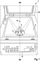
- FIG. 1 shows in a perspective schematic representation of a disposal device 1, which for the disposal of organic kitchen waste, in particular of Food waste and from equipment waste, serves.
- the disposal device comprises a receiving device 2 in the form of a funnel, which initially serves to receive the uncut organic kitchen waste.
- the receiving device 2 is in FIG. 1 shown in the form of a funnel with rectangular cross-section.
- other cross sections may also be used, such as square cross sections, round cross sections, or oval cross sections.
- a crushing device 3 is provided, which are supplied via the receiving device 2 organic kitchen waste.
- the comminution device 3 is used for comminuting the organic kitchen waste supplied via the receiving device 2.
- the crushing device 3 may be in the form of, for example, in the Figures 5 and 6 be shown and described below mill.
- a driver 4 is arranged, which protrudes from the crushing device 3 from at least partially into the receiving device 2. In other words, the driver projects at least partially into the volume V defined by the dimensions of the receiving device 2.
- the driver 4 is used for improved supply of set-up waste to the crushing device 3.
- By feeding is here understood both the actual conveyance of organic kitchen waste, for example by means of a screw conveyor, as well as the conveyance of the organic kitchen waste by pre-crushing or mechanical shaking, to correspondingly easy , loose and dry set-up waste, which hitherto jammed in the receiving device 2, to be able to feed to the shredding device 3.
- the driver 4 prepares the organic kitchen waste so and / or moves them so that they Crushing device 3 are fed or slip into this.
- the driver 4 may be provided with pre-shredders as described below to pre-shred the typically light, loose and dry set-up scrapes so that they will slide more easily toward the shredder 3 in accordance with smaller set-up scrap and will not be able to become wedged together as much.
- the driver 4 may be provided with a vibrating device to let the light, loose and dry set-up waste by shaking further down to the crushing device 3.
- the driver 4 may be provided with a conveying device, for example in the form of a screw conveyor, by means of which the light, loose and dry set-up waste is conveyed in the direction of the comminuting device 3. The transport of food remains is not hindered by the driver 4.
- a conveying device for example in the form of a screw conveyor, by means of which the light, loose and dry set-up waste is conveyed in the direction of the comminuting device 3. The transport of food remains is not hindered by the driver 4.
- Disposal device 1 shown schematically further comprises a cover 10, by means of which the receiving device 2 can be covered.
- the receiving device 2 must be covered with the cover 10 before the crushing device 3 and the driver 4 are put into operation and start to rotate.
- the lid 10 prevents spillage of organic kitchen waste from the disposal device 1 while they are transported by the driver 4 to the crushing device 3 and during the actual crushing of organic kitchen waste in the crushing device 3. This is particularly advantageous if the crushing device 3 in shape a fast-rotating mill is provided, for example, with speeds of about 1400 U / min.
- the lid 10 is there to avoid that users engage in the receiving device 2 in when the Crushing device 3 is operated.
- the cover 10 is advantageously equipped with a safety switch such that the crushing device 3 and the driver 4 can only be operated when the flap 10 is closed.
- the disposal device 1 can be operated by a user.
- a water nozzle 14 for feeding process water into the receiving device 2 is provided in order to be able to produce sufficiently high water content in the case of dry organic kitchen waste in order to allow a subsequent pumping out of the biomass comminuted by the comminuting device 3.
- the water supply nozzle 14 can also be used for cleaning the receiving device 2 and the crushing device 3 and the driver 4. For cleaning, however, at least one further water supply nozzle may be provided at a different location in the receiving device 2.
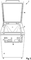
- FIG. 2 is the disposal device 1 of FIG. 1 once again shown completely in a schematic perspective view, wherein also here the lid 10 is open. Owing to the perspective, at least the comminution unit 3 adjoining the receiving device 2 at the bottom is not visible.
- the driver 4 is arranged coaxially with the crushing unit 3, wherein the axis of rotation 400 of the driver 4 extends coaxially along the axis of rotation 300 of the crushing unit 3.
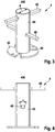
- the driver 4 is in FIG. 3 shown in a schematic perspective view.
- the driver axis 400 is surrounded by the driver shaft 40, which preferably has a diameter d, which is dimensioned so that a formation of braids from the organic kitchen waste to be processed on the shaft 40 is reduced or avoided.
- the diameter d of the shaft is about 50mm to 60mm.
- the surface of the shaft 40 of the driver 4 is advantageously equipped so that the adhesion of organic kitchen waste is largely avoided. Also by the choice of the diameter d of the shaft 40, adhesion of organic kitchen waste can be reduced, since corresponding centrifugal forces can be generated by the correspondingly higher peripheral speeds.
- a flange 42 with recesses 44 is provided, such that the driver 3 at the in the FIG. 3 not shown but from the FIG. 1 known crushing device 3 can be flanged.
- the driver 3 can be coupled via a slip clutch or a comparable coupling to the crushing device 3, in the case of introducing foreign substances such as cutlery, crockery, screws or bone, in the receiving device 2 damage to the driver 4 and to avoid the associated with this crushing device 3.
- Perpendicular to the axis of rotation 400 of the driver 4 extend as shown FIG. 3 to recognize pre-shredder 46, which serve to pre-shred loose set-up waste so that they slip in the receiving device 2 better in the direction of the crushing device 3 and this can be fed easier.
- the pre-crushing blades 46 are substantially triangular in cross section in the embodiment shown and are designed as blunt blades.
- the respective flanks of the pre-comminuting blades 46 are inclined towards the comminution device 3. To this Way, the organic kitchen waste, which is struck by the respective Vorzerklein knife 46, crushed, in particular cut and / or smashed.
- the angle a which is enclosed by the triangular shape of the pre-comminuting blade 46, is approximately 60 ° in the exemplary embodiment shown.
- the triangular design of the pre-comminuting blade 46 further enables the driver 4 to be operated in both possible directions of rotation of the comminution device 3.
- the driver 4 four pre-comminuting 46 are provided, each extending two of these Vorzerkleiners 46 on opposite sides of the shaft 40 out.
- the two pairs of pre-comminuting blades 46 are mutually perpendicular and spaced apart along the axis of rotation 400.
- the two pairs of pre-comminuting blades 46 are spaced along the axis of rotation 400 by approximately 70 mm.
- the pre-comminuting blades 46 and the shaft 40 and the flange 42 are adjusted in such a way that even high rotational speeds in the range of approximately 1400 rpm. around the rotary shaft 400 around easily possible without imbalances arise.
- FIG. 4 shows the driver 4 again in a schematic side view, wherein once again the arrangement of the pre-comminuting 46 along the axis of rotation 400 of the driver 4, as well as their triangular shape is clear.
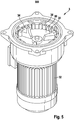
- FIG. 5 shows in a schematic perspective view of the crushing device 3.
- the crushing device 3 comprises a rotor 30 which rotates about a rotation axis 300 around and is driven by a motor 32, with the motor shaft of the rotor 30 is connected accordingly.
- the motor 32 is advantageously provided with a strong brake, which at an opening of the lid 10 during the operation of the crushing device 3 stops this immediately.
- the rotor 30 comprises differently shaped drivers 34, which carry the organic kitchen waste to be comminuted and correspondingly set in a rotational movement.
- a knife ring 36 is provided which surrounds the rotor 30 and which serves as a stator.
- the organic kitchen waste, which is rotated by the rotor 30 in a rotational movement, are accordingly pressed by the centrifugal forces against the knife rim 36 and guided along the knife ring 36 in such a way that comminution takes place in the corresponding spaces between the knives.
- the drivers 34 in turn strike along the blade ring 36 so that organic kitchen waste extending through the interspaces between the blades 36 can be cut off by the catch 34.
- Other embodiments of the crushing device 3 are also conceivable. Important for the crushing device 3 is merely that it is able to shred organic kitchen waste so that they can be subsequently pumped by a pump.
- FIG. 6 shows the shredding unit 3 again in a plan view in which the geometric arrangement of the rotor 30, the driver 34 and the blade ring 36 is clearly visible.
- FIG. 7 shows a schematic view of the disposal device 1 in a schematic sectional view, wherein the receiving device 2 is again funnel-shaped, to a targeted feeding the to get into the receiving device 2 introduced organic kitchen waste to the crushing device 3.
- the driver 4 extends clearly though not completely into the receiving device 2 and in particular extends into the volume V formed by the receiving device 2.
- the volume V formed by the receiving device 2 is defined here by the volume located between the upper edge 20 and the lower edge 22 of the funnel.
- the depth by which the driver 4 extends into the receiving device 2 depends on which organic kitchen waste to be treated. Furthermore, the depth in this embodiment is dependent on how far the pre-reduction blades 46 of the driver 4 are removed from the wall of the feed hopper 2. This distance D must be dimensioned so that even larger light equipment waste can still slip between the fast rotating Vorzerkleiner blades 46 and the wall of the receiving device 2.
- FIG. 7 Also schematically shown is a pump 5 for pumping out the biomass and a tank 6 for receiving the pumped biomass.
- the rotor of the comminution device 3 rotates advantageously at a high speed, for example 1400 revolutions / minute, in order to achieve a fine breaking of the organic kitchen waste and at the same time also to press lighter kitchen waste against the knife ring due to the generated high centrifugal force.
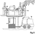
- FIG. 8 schematically shows a complete disposal system in a large kitchen, comprising a set-up station, at which set-up waste, which arise during the preparation of food, are introduced into a disposal device 70.
- a rinsing station is provided in which food waste is introduced into a corresponding disposal device 72, wherein both the set-up waste and the food waste by the disposal devices 70, 72 are comminuted and into a fine, pumpable biomass, preferably with a dry matter between 15% and 25% to be crushed.
- This pumpable biomass is pumped by the pump 5 into the tank 6, from where it can be transported by means of a tanker 74 to a biogas plant.
Landscapes
- Engineering & Computer Science (AREA)
- Food Science & Technology (AREA)
- Environmental & Geological Engineering (AREA)
- Health & Medical Sciences (AREA)
- Life Sciences & Earth Sciences (AREA)
- Hydrology & Water Resources (AREA)
- Public Health (AREA)
- Water Supply & Treatment (AREA)
- Crushing And Pulverization Processes (AREA)
- Processing Of Solid Wastes (AREA)
Description
Die vorliegende Erfindung betrifft einen Mitnehmer sowie eine Entsorgungsvorrichtung für organische Küchenabfälle gemäß dem Oberbegriff des Anspruchs 1 bzw. des Anspruchs 6.The present invention relates to a driver and a disposal device for organic kitchen waste according to the preamble of claim 1 and of
Organische Küchenabfälle in Form von Speiseabfällen und Rüstabfällen fallen beispielsweise in Großküchen, Kantinen, Hotels, Gemeinschaftsverpflegungseinrichtungen sowie in der Gastronomie täglich in großen Mengen an. Diese organischen Küchenabfälle können als Grundstoff für die Erzeugung regenerativer Energie in Biogasreaktoren verwendet werden. Hierzu ist es notwendig, die organischen Küchenabfälle so zu behandeln, dass sie lagerfähig und transportfähig sind.Organic kitchen waste in the form of catering waste and equipment waste, for example, in large kitchens, canteens, hotels, communal catering and in the catering every day in large quantities. This organic kitchen waste can be used as a raw material for the production of renewable energy in biogas reactors. For this purpose, it is necessary to treat the organic kitchen waste so that they are storable and transportable.
Organische Küchenabfälle lassen sich grob in zwei unterschiedliche Kategorien aufteilen, nämlich in Speiseabfälle und Rüstabfälle. Die Aufteilung ergibt sich sowohl aus dem Entstehungsort als auch aus dem Charakter der jeweiligen organischen Küchenabfälle.Organic kitchen waste can roughly be divided into two different categories, namely food waste and set-aside waste. The division results both from the place of origin and from the character of the respective organic kitchen waste.
Unter Speiseabfällen werden Reste bereits zubereiteter Speisen verstanden. Speiseabfälle fallen beispielsweise bei der Rücknahme von Tellern und Tabletts von den jeweiligen Gästen, Mitarbeitern oder Patienten an, bevor diese Teller oderFood waste is understood as the remains of already prepared food. Food waste, for example, when returning plates and trays by the respective guests, employees or patients, before these plates or
Tabletts gespült werden. Beispielsweise fallen in Krankenhäusern typischerweise pro Patient und Mahlzeit Speiseabfälle in einer Menge von ca. 250 g an. Auch in der Gastronomie, Hotelerie sowie in Kantinen fallen große Mengen von Speiseabfällen an.Trays are rinsed. For example, in hospitals, food waste is typically incurred per patient and meal in an amount of about 250 g. Large quantities of catering waste are also produced in restaurants, hotels and canteens.
Bei der Zubereitung der Speisen fallen in den jeweiligen Küchen an den Rüststationen Rüstabfälle an, beispielsweise Obst- und Gemüseschalen, Salatblätter und Kohlblätter, Wurzeln sowie andere organische Reste noch nicht zubereiteter Speiserohstoffe, die für die eigentliche Speisezubereitung vorbereitet werden.In the preparation of food falling into the respective kitchens at the set-up equipment Waste, for example, fruit and vegetable husks, lettuce leaves and cabbage leaves, roots and other organic remains of not yet prepared food raw materials, which are prepared for the actual food preparation.
Zur Entsorgung und Lagerung der organischen Küchenabfälle ist ein System bekannt, bei welchem die organischen Küchenabfälle in eine Entsorgungsvorrichtung gegeben werden, in welcher sie mittels einer Zerkleinerungsvorrichtung in Form einer Mühle, teilweise unter Zugabe von Wasser, so zerkleinert werden, dass sie anschließend in einer weitgehend homogenisierten Form in entsprechende Lagertanks abgepumpt werden können. Von diesen Lagertanks aus wird die dann weitgehend homogenisierte Biomasse mittels eines Transportfahrzeuges zu einer Biogasanlage transportiert, in welcher die Biomasse fermentiert wird, wobei die bei der Fermentierung entstehenden Faulgase, insbesondere Methangas, zur Erzeugung elektrischer Energie und/oder Wärmeenergie verwendet wird. Auf diese Weise können organische Küchenabfälle recycled werden und aus diesen umweltfreundlich erneuerbare Energie gewonnen werden.For disposal and storage of organic kitchen waste, a system is known in which the organic kitchen waste is placed in a disposal device in which they are comminuted by means of a crushing device in the form of a mill, partially with the addition of water so that they subsequently in a largely homogenized form can be pumped into appropriate storage tanks. From these storage tanks, the then largely homogenized biomass is transported by means of a transport vehicle to a biogas plant, in which the biomass is fermented, wherein the fermentation resulting in fumigants, especially methane gas, is used to generate electrical energy and / or heat energy. In this way, organic kitchen waste can be recycled and recovered from this environmentally friendly renewable energy.
Der Charakter der oben beschriebenen Speiseabfälle und Rüstabfälle unterscheidet sich grundlegend. Speiseabfälle sind typischerweise kompakt, schwer und feucht. Rüstabfälle sind typischerweise locker, leicht und trocken. Um einen guten Wirkungsgrad der Entsorgungsvorrichtung zu erreichen, wurden daher bislang Speiseabfälle und Rüstabfälle gemeinsam in der Entsorgungsvorrichtung behandelt.The character of the food waste and equipment waste described above is fundamentally different. Food waste is typically compact, heavy and moist. Set-up waste is typically loose, light and dry. In order to achieve a good efficiency of the disposal device, therefore, food waste and set-up waste have so far been treated together in the disposal device.
Die
Die
Die
Die
Die
Die
Die
Die
Die
Die
Die
Die
Beschreibung Es ist eine Aufgabe der vorliegenden Erfindung, die Behandlung von Rüstabfällen in einer Entsorgungsvorrichtung zu verbessern.Description It is an object of the present invention to improve the treatment of set-up waste in a disposal device.
Die genannte Aufgabe wird durch einen Mitnehmer zum Zuführen organischer Küchenabfälle mit den Merkmalen des Anspruchs 1 gelöst.The above object is achieved by a driver for supplying organic kitchen waste with the features of claim 1.
Die genannte Aufgabe wird weiterhin auch durch eine Entsorgungsvorrichtung für organische Küchenabfälle mit den Merkmalen des Anspruchs 6 gelöst.The above object is further achieved by a disposal device for organic kitchen waste with the features of
Vorteilhafte Weiterbildungen ergeben sich jeweils aus den Unteransprüchen.Advantageous developments emerge in each case from the subclaims.
Durch den Mitnehmer beziehungsweise durch das Vorsehen des Mitnehmers wird eine Entsorgungsvorrichtung unabhängiger von der Art des organischen Küchenabfalls, der in eine Aufnahmevorrichtung eingefüllt wird. Insbesondere wird so auch eine Beladung der Entsorgungsvorrichtung ausschließlich mit lockeren, trockenen und leichten Rüstabfällen möglich, da diese Rüstabfälle nun mittels des Mitnehmers zu der Zerkleinerungsvorrichtung transportiert werden können bzw. durch den Mitnehmer derart vorzerkleinert werden, dass sie durch ihr Eigengewicht in die Zerkleinerungsvorrichtung gelangen.By the driver or by the provision of the driver, a disposal device is independent of the type of organic kitchen waste, which is filled in a receiving device. In particular, as a loading of the disposal device is possible only with loose, dry and light equipment waste, since these set-waste can now be transported by means of the driver to the crushing device or are pre-shredded by the driver so that they get into the crushing device by its own weight.
Die trichterförmige Aufnahmevorrichtung weist bevorzugt einen quadratischen Querschnitt, einen rechteckigen Querschnitt, einen ovalen Querschnitt oder einen runden Querschnitt auf.The funnel-shaped receiving device preferably has a square cross section, a rectangular cross section, an oval cross section or a round cross section.
Am unteren Ende der trichterförmigen Aufnahmevorrichtung ist die Zerkleinerungsvorrichtung bevorzugt derart angeordnet, dass von oben eingefüllte organische Küchenabfälle durch die Schwerkraft zu der Zerkleinerungsvorrichtung hin gelangen.At the lower end of the funnel-shaped receiving device, the comminution device is preferably arranged such that organic kitchen waste filled from above passes by gravity to the comminuting device.
Der Mitnehmer ist mit der Zerkleinerungsvorrichtung drehfest verbunden, so dass er zusammen mit dieser rotiert. Auf diese Weise wird eine einfache Umrüstung bereits bestehender Entsorgungsvorrichtungen möglich.The driver is rotatably connected to the crushing device, so that it rotates together with this. In this way, a simple conversion of existing disposal devices is possible.
Unter "in die Aufnahmevorrichtung hineinragen" wird verstanden, dass der Mitnehmer sich soweit in die Aufnahmevorrichtung herein erstreckt, dass ein Mitnehmen von Rüstabfällen zuverlässig möglich ist. Ein Hereinragen des vollständigen Mitnehmers in die Aufnahmevorrichtung ist jedoch nicht erforderlich. Die Tiefe, um welche der Mitnehmer in die Aufnahmevorrichtung hereinragt, wird bestimmt durch mehrere Faktoren, insbesondere durch den Steigungswinkel des Aufnahmetrichters, wobei der Mitnehmer relativ zu dem Trichter so dimensioniert sein muss, dass auch größere Rüstabfälle zwischen der Trichterwand der Aufnahmevorrichtung und dem Mitnehmer so rutschen können, dass sie schlussendlich vom Mitnehmer erfasst werden können.Under "protrude into the receiving device" is understood that the driver so far in the Receiving device extends in that a take away of set-up waste is reliably possible. A Hereinragen the complete driver in the receiving device is not required. The depth by which the driver protrudes into the receiving device is determined by several factors, in particular by the pitch angle of the receiving hopper, wherein the driver must be dimensioned relative to the hopper so that even larger set-up waste between the hopper wall of the receiving device and the driver so can slip, that they can be finally captured by the driver.
Der Mitnehmer weist eine koaxial zu der Drehachse der Zerkleinerungsvorrichtung angeordnete Drehachse auf.The driver has a coaxial with the axis of rotation of the crushing device arranged axis of rotation.
Bevorzugt weist der Mitnehmer eine sich koaxial zu der Drehachse erstreckende Welle auf, wobei die Welle bevorzugt einen Durchmesser aufweist, welcher die Ausbildung von Zöpfen sowie das Anhaften von organischen Küchenabfällen reduziert. Bevorzugt liegt der Durchmesser der Welle in einem Bereich von 40mm bis 70mm, besonders bevorzugt im Bereich von 50mm bis 60mm. Auf diese Weise wird nicht nur die Neigung zur Zopfbildung verringert, sondern auch eine Stabilität der Welle gegen äußere Störungen verbessert, beispielsweise gegenüber Störungen durch das Einbringen von Fremdstoffen wie Besteck, Schrauben oder Knochen in die Aufnahmevorrichtung.Preferably, the driver has a shaft extending coaxially to the axis of rotation, wherein the shaft preferably has a diameter which reduces the formation of braids and the adhesion of organic kitchen waste. Preferably, the diameter of the shaft is in a range of 40mm to 70mm, more preferably in the range of 50mm to 60mm. In this way, not only the tendency to braid formation is reduced, but also a stability of the shaft against external disturbances improved, for example against interference from the introduction of foreign substances such as cutlery, screws or bones in the receiving device.
Der Mitnehmer weist mindestens ein senkrecht zu seiner Drehachse angeordnetes Vorzerkleinerungsmesser zur Zerkleinerung organischer Küchenabfälle auf, bevorzugt zum Zerschneiden oder Zerschlagen der organischen Küchenabfälle.The driver has at least one pre-shredder arranged perpendicular to its axis of rotation for comminuting organic kitchen waste, preferably for cutting or smashing the organic kitchen waste.
Das Vorzerkleinerungsmesser ist als ein Dreiecksmesser ausgebildet, welches zu der Zerkleinerungsvorrichtung hin gerichtete schräge Messerflanken aufweist. Der Winkel, den die Messerflanken einschließen, liegt bevorzugt in einem Bereich von 40° bis 80°, bevorzugter in einem Bereich von 50° bis 70°, besonders bevorzugt bei ca. 60°. Durch die zu der Zerkleinerungsvorrichtung hin geneigten Messerflanken wird der organische Küchenabfall, der von dem jeweiligen Vorzerkleinerungsmesser getroffen wird, zerkleinert. Der von den jeweiligen Flanken getroffene organische Küchenabfall erhält weiterhin durch die zur Zerkleinerungsvorrichtung hin geneigten Flanken einen Impuls zu dieser hin. Hierdurch wird der organische Küchenabfall der Zerkleinerungsvorrichtung noch besser zugeführt.The pre-comminuting knife is designed as a triangular knife, which has oblique knife edges directed towards the comminution device. The angle which the knife edges include is preferably in a range of 40 ° to 80 °, more preferably in a range of 50 ° to 70 °, particularly preferably about 60 °. By inclined to the crushing device knife edges of the organic kitchen waste that is struck by the respective pre-shredder, crushed. The organic kitchen waste struck by the respective flanks continues to receive an impulse through the flanks which are inclined towards the shredding device. As a result, the organic kitchen waste of the crushing device is supplied even better.
Der Mitnehmer kann Rüttelmittel und/oder Fördermittel zur Auflockerung und/oder Förderung der organischen Küchenabfälle zu der Zerkleinerungsvorrichtung aufweisen.The driver may have shaking means and / or conveying means for loosening and / or conveying the organic kitchen waste to the crushing device.
Um den Mitnehmer an die Zerkleinerungsvorrichtung anflanschen zu können, kann dieser einen Flansch aufweisen, wobei der Flansch bevorzugt mindestens eine Ausnehmung zur Aufnahme eines Mitnehmers der Zerkleinerungsvorrichtung aufweisen kann.In order to be able to flange the driver on the comminution device, it may have a flange, wherein the flange may preferably have at least one recess for receiving a driver of the comminuting device.
Die Entsorgungsvorrichtung weist bevorzugt eine Pumpe zum Abpumpen der in der Zerkleinerungsvorrichtung zerkleinerten organischen Küchenabfälle auf, wobei die Pumpe mit der Zerkleinerungsvorrichtung verbunden ist.The disposal device preferably has a pump for pumping out the organic kitchen waste shredded in the comminution device, the pump being connected to the comminuting device.
Die Zerkleinerungsvorrichtung kann dabei einen Rotor und einen den Rotor umgebenden Messerkranz aufweisen.The comminuting device can have a rotor and a blade ring surrounding the rotor.
Nachfolgend wird die vorliegende Offenbarung anhand der in den Zeichnungen der Figuren gezeigten konkreten Ausführungsbeispiele beschrieben:
- Figur 1
- zeigt eine Entsorgungsvorrichtung gemäß einem ersten Ausführungsbeispiel in einer schematischen perspektivischen Ansicht;
Figur 2- zeigt die Entsorgungsvorrichtung der
Figur 1 in einer weiteren schematischen perspektivischen Ansicht; - Figur 3
- zeigt einen Mitnehmer gemäß einem Ausführungsbeispiel in einer schematischen perspektivischen Ansicht;
Figur 4- zeigt den Mitnehmer der
Figur 3 in einer Seitenaufsicht; Figur 5- zeigt eine Zerkleinerungsvorrichtung, die in einer Entsorgungsvorrichtung verwendet werden kann, in einer schematischen perspektivischen Ansicht;
Figur 6- zeigt die
Zerkleinerungsvorrichtung der Figur 5 in einer Draufsicht; - Figur 7
- zeigt eine schematische seitliche Schnittansicht durch eine Entsorgungsvorrichtung in einem weiteren Ausführungsbeispiel; und
- Figur 8
- zeigt schematisch ein Entsorgungssystem, welches eine Entsorgungsvorrichtung gemäß der vorliegenden Offenbarung verwendet.
- FIG. 1
- shows a disposal device according to a first embodiment in a schematic perspective view;
- FIG. 2
- shows the disposal device of
FIG. 1 in a further schematic perspective view; - FIG. 3
- shows a driver according to an embodiment in a schematic perspective view;
- FIG. 4
- shows the driver of the
FIG. 3 in a side supervision; - FIG. 5
- shows a shredding device that can be used in a disposal device, in a schematic perspective view;
- FIG. 6
- shows the crushing device of
FIG. 5 in a plan view; - FIG. 7
- shows a schematic sectional side view through a disposal device in a further embodiment; and
- FIG. 8
- schematically shows a disposal system, which uses a disposal device according to the present disclosure.
In der folgenden Beschreibung bevorzugter Ausführungsbeispiele werden gleiche oder ähnliche Komponenten mit den gleichen Bezugszeichen versehen und auf eine wiederholte Beschreibung der jeweiligen Komponenten in den nachfolgenden Figuren wird teilweise verzichtet, um Redundanzen zu vermeiden.In the following description of preferred embodiments, the same or similar components are denoted by the same reference numerals, and a repeated description of the respective components in the following figures will be omitted in part to avoid redundancy.
Am unteren Ende der Aufnahmevorrichtung 2 ist eine Zerkleinerungsvorrichtung 3 vorgesehen, welcher über die Aufnahmevorrichtung 2 organische Küchenabfälle zugeführt werden. Die Zerkleinerungsvorrichtung 3 dient zur Zerkleinerung der über die Aufnahmevorrichtung 2 zugeführten organischen Küchenabfälle. Die Zerkleinerungsvorrichtung 3 kann in Form der beispielsweise in den
An der Zerkleinerungsvorrichtung 3 ist ein Mitnehmer 4 angeordnet, welcher von der Zerkleinerungsvorrichtung 3 aus zumindest teilweise in die Aufnahmevorrichtung 2 hereinragt. Mit anderen Worten ragt der Mitnehmer zumindest teilweise in das durch die Dimensionen der Aufnahmevorrichtung 2 definierte Volumen V hinein.At the crushing device 3, a
Der Mitnehmer 4 dient zum verbesserten Zuführen von Rüstabfällen zu der Zerkleinerungsvorrichtung 3. Unter Zuführen wird hier sowohl das tatsächliche Fördern der organischen Küchenabfälle beispielsweise mittels einer Förderschnecke, als auch das Förderbarmachen des organischen Küchenabfalls durch ein Vorzerkleinern oder ein mechanisches Rütteln verstanden, um entsprechend auch leichte, lockere und trockene Rüstabfälle, die bisher in der Aufnahmevorrichtung 2 verklemmten, zur Zerkleinerungsvorrichtung 3 zuführen zu können. Der Mitnehmer 4 bereitet also die organischen Küchenabfälle so auf und/oder bewegt sie derart, dass sie der Zerkleinerungsvorrichtung 3 zugeführt werden bzw. in diese hereinrutschen.The
Der Mitnehmer 4 kann mit weiter unten beschriebenen Vorzerkleinerungsmessern versehen ein, um die typischer Weise leichten, lockeren und trockenen Rüstabfälle vorzuzerkleinern, so dass diese dann entsprechend kleineren Rüstabfälle einfacher in Richtung der Zerkleinerungsvorrichtung 3 rutschen und sich nicht mehr so stark ineinander verkeilen können.The
Weiterhin kann der Mitnehmer 4 mit einer Rüttelvorrichtung versehen sein, um die leichten, lockeren und trockenen Rüstabfälle durch Rütteln weiter nach unten zu der Zerkleinerungsvorrichtung 3 rutschen zu lassen.Furthermore, the
In einer weiteren Variante kann der Mitnehmer 4 mit einer Fördervorrichtung, beispielsweise in Form einer Förderschnecke, versehen sein, mittels welcher die leichten, lockeren und trockenen Rüstabfälle in Richtung der Zerkleinerungsvorrichtung 3 gefördert werden. Der Transport von Speiseresten wird durch den Mitnehmer 4 nicht behindert.In a further variant, the
Die in
Mittels einer schematisch gezeigten Bedieneinheit 12 kann die Entsorgungsvorrichtung 1 durch einen Nutzer bedient werden.By means of a
Eine Wasserdüse 14 zum Einspeisen von Prozesswasser in die Aufnahmevorrichtung 2 ist vorgesehen, um bei trockenen organischen Küchenabfällen hinreichend viel Wassergehalt herstellen zu können, um ein nachfolgendes Abpumpen der durch die Zerkleinerungsvorrichtung 3 zerkleinerten Biomasse zu ermöglichen. Zum Abpumpen der durch die Zerkleinerungsvorrichtung 3 zerkleinerten, feuchten und weitgehend homogenisierten Biomasse ist nach der Zerkleinerungsvorrichtung 3 eine entsprechend dimensionierte Pumpe vorgesehen, die in der beschriebenen Figur jedoch nicht gezeigt ist.A
Die Wasserzuführdüse 14 kann weiterhin auch zur Reinigung der Aufnahmevorrichtung 2 sowie der Zerkleinerungsvorrichtung 3 und des Mitnehmers 4 verwendet werden. Zur Reinigung kann aber auch mindestens eine weitere Wasserzuführdüse an einer anderen Stelle in der Aufnahmevorrichtung 2 vorgesehen sein.The
In
Wie sich beispielsweise aus
Der Mitnehmer 4 ist in
Ein Flansch 42 mit Ausnehmungen 44 ist vorgesehen, derart, dass der Mitnehmer 3 an der in der
Senkrecht zu der Drehachse 400 des Mitnehmers 4 erstrecken sich, wie aus
Die Vorzerkleinerungsmesser 46 haben in der gezeigten Ausführungsform im Wesentlichen einen dreieckigen Querschnitt und sind als stumpfe Messer ausgeführt. Die jeweiligen Flanken der Vorzerkleinerungsmesser 46 sind zu der Zerkleinerungsvorrichtung 3 hin geneigt ausgebildet. Auf diese Weise wird der organische Küchenabfall, welcher von dem jeweiligen Vorzerkleinerungsmesser 46 getroffen wird, zerkleinert, insbesondere zerschnitten und/oder zerschlagen. Durch die Ausrichtung der Flanken des Vorzerkleinerungsmessers 46 auf die Zerkleinerungsvorrichtung 3 hin wird weiterhin erreicht, dass der jeweilige organische Küchenabfall mit einem Impuls in Richtung auf die Zerkleinerungsvorrichtung 3 hin beaufschlagt wird, wodurch der organische Küchenabfall in Richtung der Zerkleinerungsvorrichtung 3 gefördert wird.The
Der Winkel a, der durch die Dreiecksform des Vorzerkleinerungsmessers 46 eingeschlossen wird, liegt in dem gezeigten Ausführungsbeispiel bei ca. 60°. Die dreieckige Ausführung des Vorzerkleinerungsmessers 46 ermöglicht weiterhin, dass der Mitnehmer 4 in beiden möglichen Drehrichtungen der Zerkleinerungsvorrichtung 3 betrieben werden kann.The angle a, which is enclosed by the triangular shape of the
In der in
Die Vorzerkleinerungsmesser 46 sowie die Welle 40 und der Flansch 42 sind derart ausjustiert, dass auch hohe Drehzahlen im Bereich von ca. 1400 U/Min. um die Drehwelle 400 herum problemlos möglich werden, ohne dass Unwuchten entstehen.The
Der Rotor 30 umfasst unterschiedlich geformte Mitnehmer 34, welche die zu zerkleinernden organischen Küchenabfälle mitführen und entsprechend in eine Rotationsbewegung versetzen. Ein Messerkranz 36 ist vorgesehen, welcher den Rotor 30 umgibt und welcher als Stator dient. Die von dem Rotor 30 in eine Rotationsbewegung versetzten organischen Küchenabfälle werden entsprechend durch die Zentrifugalkräfte an den Messerkranz 36 gedrückt und an diesem so entlang geführt, dass eine Zerkleinerung in den entsprechenden Zwischenräumen zwischen den Messern stattfindet. Die Mitnehmer 34 streichen ihrerseits an dem Messerkranz 36 entlang, so dass sich durch die zwischen den Messern 36 befindlichen Zwischenräume hindurch erstreckenden organischen Küchenabfällen durch den Mitnehmer 34 abgeschnitten werden können. Andere Ausführungen der Zerkleinerungsvorrichtung 3 sind ebenfalls denkbar. Wichtig für die Zerkleinerungsvorrichtung 3 ist lediglich, dass sie dazu in der Lage ist, organische Küchenabfälle so zu zerkleinern, dass diese nachfolgend mittels einer Pumpe abgepumpt werden können.The
In dieser Figur ist deutlich zu erkennen, dass sich der Mitnehmer 4 deutlich, wenn auch nicht vollständig, in die Aufnahmevorrichtung 2 herein erstreckt und sich insbesondere in das von der Aufnahmevorrichtung 2 gebildete Volumen V hinein erstreckt. Das durch die Aufnahmevorrichtung 2 gebildete Volumen V definiert sich hier durch das zwischen der oberen Kante 20 und der unteren Kante 22 des Trichters befindliche Volumen.It can clearly be seen in this figure that the
Die Tiefe, um welche sich der Mitnehmer 4 in die Aufnahmevorrichtung 2 herein erstreckt, ist unter anderem abhängig davon, welche organischen Küchenabfälle behandelt werden sollen. Weiterhin ist die Tiefe in dieser Ausführungsvariante abhängig davon, wie weit die Vorzerkleinerungsmesser 46 des Mitnehmers 4 von der Wand des Zuführtrichters 2 entfernt sind. Dieser Abstand D muss so bemessen sein, dass auch größere leichte Rüstabfälle noch zwischen den schnell rotierenden Vorzerkleinerungsmessern 46 und der Wand der Aufnahmevorrichtung 2 hindurchrutschen können.The depth by which the
In
Der Rotor der Zerkleinerungsvorrichtung 3 dreht vorteilhaft mit einer hohen Umdrehungszahl, beispielsweise 1400 Umdrehungen/Minute, um ein feines Zerschlagen der organischen Küchenabfälle zu erreichen und gleichzeitig auch leichtere Küchenabfälle aufgrund der erzeugten hohen Zentrifugalkraft gegen den Messerkranz zu drücken.The rotor of the comminution device 3 rotates advantageously at a high speed, for example 1400 revolutions / minute, in order to achieve a fine breaking of the organic kitchen waste and at the same time also to press lighter kitchen waste against the knife ring due to the generated high centrifugal force.
Claims (9)
- Carrier (4) for supplying organic kitchen waste to a shredding device (3) of a waste disposal device (1) for organic kitchen waste, characterised by a shaft (40), a rotation axis (400) which extends coaxially relative to the shaft (40) and at least one pre-shredding blade (46) which is provided on the shaft (40) and which is arranged perpendicularly to the rotation axis (400) thereof for shredding organic kitchen waste, and which is constructed as a triangular blade having flanks which are inclined in the direction towards the shredding device (3),
wherein the carrier (4) can be connected to the shredding device (3) in a rotationally secure manner, wherein the at least one pre-shredding blade (46) is arranged on the shaft in such a manner that in the connected state of the carrier (4) to the shredding device (3) it is arranged spaced apart from the shredding device (3). - Carrier (4) according to claim 1, comprising a flange (42) for flange-mounting the carrier (4) to the shredding device (3).
- Carrier (4) according to claim 1 or 2, wherein the angle (α) enclosed by the flanks of the triangular blade is in a range from 40° to 80°.
- Carrier (4) according to any one of the preceding claims, wherein at least one vibrating means for loosening and/or a conveying means for conveying the organic kitchen waste to the shredding device is provided on the shaft (40).
- Carrier (4) according to any one of the preceding claims, wherein the shaft (40) has a diameter which reduces the formation of clumps and the adhesion of organic kitchen waste, wherein the diameter (d) of the shaft (40) is in a range from 40 mm to 70 mm.
- Waste disposal device (1) for organic kitchen waste comprising a shredding device (3) for shredding organic kitchen waste and a receiving device (2) which is connected to the shredding device (3) for receiving non-shredded organic kitchen waste, wherein the receiving device (2) is constructed in a funnel-like manner,
characterised by
a carrier (4) which protrudes into the receiving device (2) according to any one of the preceding claims, for supplying organic kitchen waste to the shredding device (3),
wherein the carrier (4) is connected to the shredding device (3) in a rotationally secure manner and is arranged with the rotation axis (400) thereof coaxial relative to the rotation axis (300) of the shredding device (3). - Waste disposal device (1) according to claim 6, wherein the receiving device (2) has a square, rectangular, round or oval cross-section.
- Waste disposal device (1) according to either claim 6 or 7, wherein a pump (5) is provided for pumping away the organic kitchen waste which has been shredded in the shredding device (3) and is connected to the shredding device (3).
- Waste disposal device (1) according to any one of claims 6 to 8, wherein the shredding device (3) has a rotor (30) and a blade ring (36) which surrounds the rotor (30).
Priority Applications (2)
| Application Number | Priority Date | Filing Date | Title |
|---|---|---|---|
| EP11155675.9A EP2492405B1 (en) | 2011-02-23 | 2011-02-23 | Disposing device for organic kitchen waste and conveyor for such a disposing device |
| DE202011050658U DE202011050658U1 (en) | 2011-02-23 | 2011-07-07 | Disposal device for organic kitchen waste and driver for such a disposal device |
Applications Claiming Priority (1)
| Application Number | Priority Date | Filing Date | Title |
|---|---|---|---|
| EP11155675.9A EP2492405B1 (en) | 2011-02-23 | 2011-02-23 | Disposing device for organic kitchen waste and conveyor for such a disposing device |
Publications (2)
| Publication Number | Publication Date |
|---|---|
| EP2492405A1 EP2492405A1 (en) | 2012-08-29 |
| EP2492405B1 true EP2492405B1 (en) | 2018-04-11 |
Family
ID=44278681
Family Applications (1)
| Application Number | Title | Priority Date | Filing Date |
|---|---|---|---|
| EP11155675.9A Active EP2492405B1 (en) | 2011-02-23 | 2011-02-23 | Disposing device for organic kitchen waste and conveyor for such a disposing device |
Country Status (2)
| Country | Link |
|---|---|
| EP (1) | EP2492405B1 (en) |
| DE (1) | DE202011050658U1 (en) |
Families Citing this family (4)
| Publication number | Priority date | Publication date | Assignee | Title |
|---|---|---|---|---|
| EP2873463A1 (en) | 2013-11-18 | 2015-05-20 | BIOTrans AG | Processing device |
| PL3467214T3 (en) | 2017-10-05 | 2024-04-02 | MEIKO GREEN Waste Solutions AG | Method and device for grinding kitchen waste and/or food remnants |
| CN115625177B (en) * | 2022-10-25 | 2024-12-10 | 宁波世茂能源股份有限公司 | A device for coordinating kitchen waste, domestic waste and sludge |
| CN120961564B (en) * | 2025-08-27 | 2026-03-03 | 山东科技大学 | Kitchen garbage high-temperature biodegradation device |
Citations (3)
| Publication number | Priority date | Publication date | Assignee | Title |
|---|---|---|---|---|
| JPH1057831A (en) * | 1996-08-19 | 1998-03-03 | Hitachi Ltd | Garbage processing equipment |
| EP1685906A2 (en) * | 2005-02-01 | 2006-08-02 | Young Ki Kim | Device for treating food wastes |
| WO2007143853A1 (en) * | 2006-06-15 | 2007-12-21 | Les Equipements Pro-Jet Inc. | Shredder for organic sludges, fertilizers and the like |
Family Cites Families (9)
| Publication number | Priority date | Publication date | Assignee | Title |
|---|---|---|---|---|
| US2828083A (en) * | 1955-12-14 | 1958-03-25 | Gen Electric | Waste disposal apparatus |
| GB1200842A (en) * | 1968-02-29 | 1970-08-05 | Howard Walter Dyson | Apparatus for disintegrating solid materials |
| DE2928471C2 (en) * | 1979-07-14 | 1982-03-11 | Osnabrücker Metallwerke J.Kampschulte GmbH & Co KG, 4500 Osnabrück | Machine for shredding lumpy objects |
| IT8520484V0 (en) * | 1985-01-14 | 1985-01-14 | Ica Spa | SPAPOLATORE FOR PAPER AND / OR SIMILAR WASTE PRODUCTS. |
| JPS63126695A (en) * | 1986-11-14 | 1988-05-30 | Tago Kiyoutarou | Crude refuse treating device |
| JP2001293389A (en) * | 2000-04-17 | 2001-10-23 | Seiichi Tsunoda | Crusher |
| JP4228751B2 (en) * | 2003-03-31 | 2009-02-25 | マックス株式会社 | Garbage disposal equipment |
| JP4857722B2 (en) * | 2005-11-15 | 2012-01-18 | マックス株式会社 | Garbage disposal equipment |
| AU2010200304A1 (en) * | 2009-01-27 | 2010-08-12 | Pioneer Waste Management Holdings Trust Pty Limited | Waste treament system |
-
2011
- 2011-02-23 EP EP11155675.9A patent/EP2492405B1/en active Active
- 2011-07-07 DE DE202011050658U patent/DE202011050658U1/en not_active Expired - Lifetime
Patent Citations (3)
| Publication number | Priority date | Publication date | Assignee | Title |
|---|---|---|---|---|
| JPH1057831A (en) * | 1996-08-19 | 1998-03-03 | Hitachi Ltd | Garbage processing equipment |
| EP1685906A2 (en) * | 2005-02-01 | 2006-08-02 | Young Ki Kim | Device for treating food wastes |
| WO2007143853A1 (en) * | 2006-06-15 | 2007-12-21 | Les Equipements Pro-Jet Inc. | Shredder for organic sludges, fertilizers and the like |
Also Published As
| Publication number | Publication date |
|---|---|
| DE202011050658U1 (en) | 2012-10-09 |
| EP2492405A1 (en) | 2012-08-29 |
Similar Documents
| Publication | Publication Date | Title |
|---|---|---|
| EP2977106B1 (en) | Method and device for large-scale processing of biomass | |
| EP3467214B1 (en) | Method and device for grinding kitchen waste and/or food remnants | |
| JP2013123705A (en) | Agitation crusher | |
| DE2047006B2 (en) | Plant for shredding and partial separation of garbage | |
| DE102018212162B4 (en) | Feeder for a juicer, food processor and juicer with a feeder | |
| EP2492405B1 (en) | Disposing device for organic kitchen waste and conveyor for such a disposing device | |
| EP2092975B1 (en) | Mixing device with a mixing bowl fixed to a mix container | |
| DE3221431C2 (en) | ||
| EP3131679B1 (en) | Disposing device, disposing system and method for disposing of food waste | |
| DE1632883A1 (en) | Chopping device, especially for meat, bread or the like. | |
| DE102014004492A1 (en) | Production of biogas from straw | |
| EP1884564A1 (en) | Preparation of liquid manure and organic solids for a fermentation | |
| CN206881851U (en) | A kind of fiber multistage hobboing cutter pulverizer | |
| DE2136203A1 (en) | Waste Crusher | |
| EP0824966B1 (en) | Crushing device as well as crusher for solid or pasty waste in a liquid | |
| DE3813879A1 (en) | Comminution machine for thermoplastic refuse | |
| DE102010050863B4 (en) | Apparatus for mixing non-pumpable biomass with a liquid | |
| CN204469823U (en) | A kind of Chinese medicine is pulverized and stirring integrated machine | |
| EP2564930A1 (en) | Shredder | |
| DE202016106372U1 (en) | Chopping device for the treatment of biomass material | |
| WO2014173384A1 (en) | Device for comminuting fragmented residual products from a palm oil extraction process | |
| DE102011089615A1 (en) | Crushing device and use of such a shredding device | |
| WO2012069595A1 (en) | Apparatus and method for comminuting material | |
| CN216654817U (en) | Coconut meat mincing device for coconut juice processing | |
| DE102006054132B4 (en) | Process and apparatus for processing root crops into a fermentable suspension |
Legal Events
| Date | Code | Title | Description |
|---|---|---|---|
| PUAI | Public reference made under article 153(3) epc to a published international application that has entered the european phase |
Free format text: ORIGINAL CODE: 0009012 |
|
| 17P | Request for examination filed |
Effective date: 20110923 |
|
| AK | Designated contracting states |
Kind code of ref document: A1 Designated state(s): AL AT BE BG CH CY CZ DE DK EE ES FI FR GB GR HR HU IE IS IT LI LT LU LV MC MK MT NL NO PL PT RO RS SE SI SK SM TR |
|
| AX | Request for extension of the european patent |
Extension state: BA ME |
|
| STAA | Information on the status of an ep patent application or granted ep patent |
Free format text: STATUS: EXAMINATION IS IN PROGRESS |
|
| RAP1 | Party data changed (applicant data changed or rights of an application transferred) |
Owner name: BIOTRANS HOLDING GMBH |
|
| REG | Reference to a national code |
Ref country code: DE Ref legal event code: R079 Ref document number: 502011014021 Country of ref document: DE Free format text: PREVIOUS MAIN CLASS: E03C0001266000 Ipc: B02C0018220000 |
|
| GRAP | Despatch of communication of intention to grant a patent |
Free format text: ORIGINAL CODE: EPIDOSNIGR1 |
|
| STAA | Information on the status of an ep patent application or granted ep patent |
Free format text: STATUS: GRANT OF PATENT IS INTENDED |
|
| RIC1 | Information provided on ipc code assigned before grant |
Ipc: B02C 18/00 20060101ALI20170926BHEP Ipc: E03C 1/266 20060101ALI20170926BHEP Ipc: B02C 18/22 20060101AFI20170926BHEP |
|
| INTG | Intention to grant announced |
Effective date: 20171024 |
|
| GRAS | Grant fee paid |
Free format text: ORIGINAL CODE: EPIDOSNIGR3 |
|
| GRAA | (expected) grant |
Free format text: ORIGINAL CODE: 0009210 |
|
| STAA | Information on the status of an ep patent application or granted ep patent |
Free format text: STATUS: THE PATENT HAS BEEN GRANTED |
|
| AK | Designated contracting states |
Kind code of ref document: B1 Designated state(s): AL AT BE BG CH CY CZ DE DK EE ES FI FR GB GR HR HU IE IS IT LI LT LU LV MC MK MT NL NO PL PT RO RS SE SI SK SM TR |
|
| RAP1 | Party data changed (applicant data changed or rights of an application transferred) |
Owner name: BIOTRANS AG |
|
| REG | Reference to a national code |
Ref country code: GB Ref legal event code: FG4D Free format text: NOT ENGLISH |
|
| REG | Reference to a national code |
Ref country code: CH Ref legal event code: EP |
|
| REG | Reference to a national code |
Ref country code: AT Ref legal event code: REF Ref document number: 987417 Country of ref document: AT Kind code of ref document: T Effective date: 20180415 |
|
| REG | Reference to a national code |
Ref country code: IE Ref legal event code: FG4D Free format text: LANGUAGE OF EP DOCUMENT: GERMAN |
|
| REG | Reference to a national code |
Ref country code: DE Ref legal event code: R096 Ref document number: 502011014021 Country of ref document: DE |
|
| REG | Reference to a national code |
Ref country code: NL Ref legal event code: FP |
|
| REG | Reference to a national code |
Ref country code: SE Ref legal event code: TRGR |
|
| REG | Reference to a national code |
Ref country code: LT Ref legal event code: MG4D |
|
| PG25 | Lapsed in a contracting state [announced via postgrant information from national office to epo] |
Ref country code: BG Free format text: LAPSE BECAUSE OF FAILURE TO SUBMIT A TRANSLATION OF THE DESCRIPTION OR TO PAY THE FEE WITHIN THE PRESCRIBED TIME-LIMIT Effective date: 20180711 Ref country code: LT Free format text: LAPSE BECAUSE OF FAILURE TO SUBMIT A TRANSLATION OF THE DESCRIPTION OR TO PAY THE FEE WITHIN THE PRESCRIBED TIME-LIMIT Effective date: 20180411 Ref country code: ES Free format text: LAPSE BECAUSE OF FAILURE TO SUBMIT A TRANSLATION OF THE DESCRIPTION OR TO PAY THE FEE WITHIN THE PRESCRIBED TIME-LIMIT Effective date: 20180411 Ref country code: AL Free format text: LAPSE BECAUSE OF FAILURE TO SUBMIT A TRANSLATION OF THE DESCRIPTION OR TO PAY THE FEE WITHIN THE PRESCRIBED TIME-LIMIT Effective date: 20180411 Ref country code: NO Free format text: LAPSE BECAUSE OF FAILURE TO SUBMIT A TRANSLATION OF THE DESCRIPTION OR TO PAY THE FEE WITHIN THE PRESCRIBED TIME-LIMIT Effective date: 20180711 Ref country code: PL Free format text: LAPSE BECAUSE OF FAILURE TO SUBMIT A TRANSLATION OF THE DESCRIPTION OR TO PAY THE FEE WITHIN THE PRESCRIBED TIME-LIMIT Effective date: 20180411 |
|
| PG25 | Lapsed in a contracting state [announced via postgrant information from national office to epo] |
Ref country code: HR Free format text: LAPSE BECAUSE OF FAILURE TO SUBMIT A TRANSLATION OF THE DESCRIPTION OR TO PAY THE FEE WITHIN THE PRESCRIBED TIME-LIMIT Effective date: 20180411 Ref country code: RS Free format text: LAPSE BECAUSE OF FAILURE TO SUBMIT A TRANSLATION OF THE DESCRIPTION OR TO PAY THE FEE WITHIN THE PRESCRIBED TIME-LIMIT Effective date: 20180411 Ref country code: LV Free format text: LAPSE BECAUSE OF FAILURE TO SUBMIT A TRANSLATION OF THE DESCRIPTION OR TO PAY THE FEE WITHIN THE PRESCRIBED TIME-LIMIT Effective date: 20180411 Ref country code: GR Free format text: LAPSE BECAUSE OF FAILURE TO SUBMIT A TRANSLATION OF THE DESCRIPTION OR TO PAY THE FEE WITHIN THE PRESCRIBED TIME-LIMIT Effective date: 20180712 |
|
| PG25 | Lapsed in a contracting state [announced via postgrant information from national office to epo] |
Ref country code: PT Free format text: LAPSE BECAUSE OF FAILURE TO SUBMIT A TRANSLATION OF THE DESCRIPTION OR TO PAY THE FEE WITHIN THE PRESCRIBED TIME-LIMIT Effective date: 20180813 |
|
| REG | Reference to a national code |
Ref country code: DE Ref legal event code: R097 Ref document number: 502011014021 Country of ref document: DE |
|
| PG25 | Lapsed in a contracting state [announced via postgrant information from national office to epo] |
Ref country code: SK Free format text: LAPSE BECAUSE OF FAILURE TO SUBMIT A TRANSLATION OF THE DESCRIPTION OR TO PAY THE FEE WITHIN THE PRESCRIBED TIME-LIMIT Effective date: 20180411 Ref country code: EE Free format text: LAPSE BECAUSE OF FAILURE TO SUBMIT A TRANSLATION OF THE DESCRIPTION OR TO PAY THE FEE WITHIN THE PRESCRIBED TIME-LIMIT Effective date: 20180411 Ref country code: CZ Free format text: LAPSE BECAUSE OF FAILURE TO SUBMIT A TRANSLATION OF THE DESCRIPTION OR TO PAY THE FEE WITHIN THE PRESCRIBED TIME-LIMIT Effective date: 20180411 Ref country code: RO Free format text: LAPSE BECAUSE OF FAILURE TO SUBMIT A TRANSLATION OF THE DESCRIPTION OR TO PAY THE FEE WITHIN THE PRESCRIBED TIME-LIMIT Effective date: 20180411 Ref country code: DK Free format text: LAPSE BECAUSE OF FAILURE TO SUBMIT A TRANSLATION OF THE DESCRIPTION OR TO PAY THE FEE WITHIN THE PRESCRIBED TIME-LIMIT Effective date: 20180411 |
|
| PLBE | No opposition filed within time limit |
Free format text: ORIGINAL CODE: 0009261 |
|
| STAA | Information on the status of an ep patent application or granted ep patent |
Free format text: STATUS: NO OPPOSITION FILED WITHIN TIME LIMIT |
|
| PG25 | Lapsed in a contracting state [announced via postgrant information from national office to epo] |
Ref country code: SM Free format text: LAPSE BECAUSE OF FAILURE TO SUBMIT A TRANSLATION OF THE DESCRIPTION OR TO PAY THE FEE WITHIN THE PRESCRIBED TIME-LIMIT Effective date: 20180411 |
|
| 26N | No opposition filed |
Effective date: 20190114 |
|
| REG | Reference to a national code |
Ref country code: DE Ref legal event code: R082 Ref document number: 502011014021 Country of ref document: DE Representative=s name: DF-MP DOERRIES FRANK-MOLNIA & POHLMAN PATENTAN, DE Ref country code: DE Ref legal event code: R081 Ref document number: 502011014021 Country of ref document: DE Owner name: MEIKO GREEN WASTE SOLUTIONS AG, CH Free format text: FORMER OWNER: BIOTRANS AG, BUETSCHWILL, CH |
|
| PG25 | Lapsed in a contracting state [announced via postgrant information from national office to epo] |
Ref country code: SI Free format text: LAPSE BECAUSE OF FAILURE TO SUBMIT A TRANSLATION OF THE DESCRIPTION OR TO PAY THE FEE WITHIN THE PRESCRIBED TIME-LIMIT Effective date: 20180411 |
|
| PG25 | Lapsed in a contracting state [announced via postgrant information from national office to epo] |
Ref country code: MC Free format text: LAPSE BECAUSE OF FAILURE TO SUBMIT A TRANSLATION OF THE DESCRIPTION OR TO PAY THE FEE WITHIN THE PRESCRIBED TIME-LIMIT Effective date: 20180411 Ref country code: LU Free format text: LAPSE BECAUSE OF NON-PAYMENT OF DUE FEES Effective date: 20190223 |
|
| REG | Reference to a national code |
Ref country code: BE Ref legal event code: MM Effective date: 20190228 |
|
| REG | Reference to a national code |
Ref country code: IE Ref legal event code: MM4A |
|
| PG25 | Lapsed in a contracting state [announced via postgrant information from national office to epo] |
Ref country code: IE Free format text: LAPSE BECAUSE OF NON-PAYMENT OF DUE FEES Effective date: 20190223 |
|
| PG25 | Lapsed in a contracting state [announced via postgrant information from national office to epo] |
Ref country code: BE Free format text: LAPSE BECAUSE OF NON-PAYMENT OF DUE FEES Effective date: 20190228 |
|
| PG25 | Lapsed in a contracting state [announced via postgrant information from national office to epo] |
Ref country code: TR Free format text: LAPSE BECAUSE OF FAILURE TO SUBMIT A TRANSLATION OF THE DESCRIPTION OR TO PAY THE FEE WITHIN THE PRESCRIBED TIME-LIMIT Effective date: 20180411 |
|
| PG25 | Lapsed in a contracting state [announced via postgrant information from national office to epo] |
Ref country code: MT Free format text: LAPSE BECAUSE OF FAILURE TO SUBMIT A TRANSLATION OF THE DESCRIPTION OR TO PAY THE FEE WITHIN THE PRESCRIBED TIME-LIMIT Effective date: 20180411 |
|
| PG25 | Lapsed in a contracting state [announced via postgrant information from national office to epo] |
Ref country code: CY Free format text: LAPSE BECAUSE OF FAILURE TO SUBMIT A TRANSLATION OF THE DESCRIPTION OR TO PAY THE FEE WITHIN THE PRESCRIBED TIME-LIMIT Effective date: 20180411 |
|
| PG25 | Lapsed in a contracting state [announced via postgrant information from national office to epo] |
Ref country code: IS Free format text: LAPSE BECAUSE OF FAILURE TO SUBMIT A TRANSLATION OF THE DESCRIPTION OR TO PAY THE FEE WITHIN THE PRESCRIBED TIME-LIMIT Effective date: 20180811 |
|
| PG25 | Lapsed in a contracting state [announced via postgrant information from national office to epo] |
Ref country code: HU Free format text: LAPSE BECAUSE OF FAILURE TO SUBMIT A TRANSLATION OF THE DESCRIPTION OR TO PAY THE FEE WITHIN THE PRESCRIBED TIME-LIMIT; INVALID AB INITIO Effective date: 20110223 |
|
| PG25 | Lapsed in a contracting state [announced via postgrant information from national office to epo] |
Ref country code: MK Free format text: LAPSE BECAUSE OF FAILURE TO SUBMIT A TRANSLATION OF THE DESCRIPTION OR TO PAY THE FEE WITHIN THE PRESCRIBED TIME-LIMIT Effective date: 20180411 |
|
| PGFP | Annual fee paid to national office [announced via postgrant information from national office to epo] |
Ref country code: SE Payment date: 20240221 Year of fee payment: 14 |
|
| REG | Reference to a national code |
Ref country code: DE Ref legal event code: R082 Ref document number: 502011014021 Country of ref document: DE Representative=s name: MAUCHER JENKINS PATENTANWAELTE & RECHTSANWAELT, DE |
|
| REG | Reference to a national code |
Ref country code: SE Ref legal event code: EUG |
|
| REG | Reference to a national code |
Ref country code: CH Ref legal event code: U11 Free format text: ST27 STATUS EVENT CODE: U-0-0-U10-U11 (AS PROVIDED BY THE NATIONAL OFFICE) Effective date: 20260301 |
|
| PGFP | Annual fee paid to national office [announced via postgrant information from national office to epo] |
Ref country code: NL Payment date: 20260218 Year of fee payment: 16 |
|
| PGFP | Annual fee paid to national office [announced via postgrant information from national office to epo] |
Ref country code: GB Payment date: 20260219 Year of fee payment: 16 |
|
| PGFP | Annual fee paid to national office [announced via postgrant information from national office to epo] |
Ref country code: DE Payment date: 20260330 Year of fee payment: 16 |
|
| REG | Reference to a national code |
Ref country code: DE Ref legal event code: R081 Ref document number: 502011014021 Country of ref document: DE Owner name: MEIKO MASCHINENBAU GMBH & CO. KG, DE Free format text: FORMER OWNER: MEIKO GREEN WASTE SOLUTIONS AG, BUETSCHWILL, CH |
|
| PGFP | Annual fee paid to national office [announced via postgrant information from national office to epo] |
Ref country code: AT Payment date: 20260216 Year of fee payment: 16 |
|
| PGFP | Annual fee paid to national office [announced via postgrant information from national office to epo] |
Ref country code: FI Payment date: 20260217 Year of fee payment: 16 Ref country code: IT Payment date: 20260227 Year of fee payment: 16 |
|
| PGFP | Annual fee paid to national office [announced via postgrant information from national office to epo] |
Ref country code: FR Payment date: 20260219 Year of fee payment: 16 |
|
| PGFP | Annual fee paid to national office [announced via postgrant information from national office to epo] |
Ref country code: CH Payment date: 20260301 Year of fee payment: 16 |