EP2491908A1 - Procédé et dispositif pour fabriquer un corps d'absorption - Google Patents
Procédé et dispositif pour fabriquer un corps d'absorption Download PDFInfo
- Publication number
- EP2491908A1 EP2491908A1 EP10824813A EP10824813A EP2491908A1 EP 2491908 A1 EP2491908 A1 EP 2491908A1 EP 10824813 A EP10824813 A EP 10824813A EP 10824813 A EP10824813 A EP 10824813A EP 2491908 A1 EP2491908 A1 EP 2491908A1
- Authority
- EP
- European Patent Office
- Prior art keywords
- absorbent body
- placement surface
- absorbent
- outer circumferential
- rotating drum
- Prior art date
- Legal status (The legal status is an assumption and is not a legal conclusion. Google has not performed a legal analysis and makes no representation as to the accuracy of the status listed.)
- Withdrawn
Links
- 238000004519 manufacturing process Methods 0.000 title claims abstract description 65
- 238000000034 method Methods 0.000 title claims description 23
- 238000010521 absorption reaction Methods 0.000 title description 2
- 230000002745 absorbent Effects 0.000 claims abstract description 303
- 239000002250 absorbent Substances 0.000 claims abstract description 303
- 239000000835 fiber Substances 0.000 claims abstract description 110
- 238000003475 lamination Methods 0.000 claims abstract description 47
- 229920000247 superabsorbent polymer Polymers 0.000 claims abstract description 41
- 239000007788 liquid Substances 0.000 claims abstract description 30
- 238000010030 laminating Methods 0.000 claims abstract description 23
- 238000000465 moulding Methods 0.000 claims abstract description 23
- 230000007246 mechanism Effects 0.000 claims description 6
- 239000007789 gas Substances 0.000 description 19
- 230000008569 process Effects 0.000 description 17
- 238000003825 pressing Methods 0.000 description 14
- 239000004583 superabsorbent polymers (SAPs) Substances 0.000 description 9
- 238000011144 upstream manufacturing Methods 0.000 description 6
- 230000000694 effects Effects 0.000 description 5
- 230000035699 permeability Effects 0.000 description 4
- 229920000642 polymer Polymers 0.000 description 4
- 230000008901 benefit Effects 0.000 description 3
- 230000002093 peripheral effect Effects 0.000 description 3
- 238000012545 processing Methods 0.000 description 3
- 230000001629 suppression Effects 0.000 description 3
- IJGRMHOSHXDMSA-UHFFFAOYSA-N Atomic nitrogen Chemical compound N#N IJGRMHOSHXDMSA-UHFFFAOYSA-N 0.000 description 2
- 229920000297 Rayon Polymers 0.000 description 2
- 229920002678 cellulose Polymers 0.000 description 2
- 239000001913 cellulose Substances 0.000 description 2
- 230000008859 change Effects 0.000 description 2
- 230000003247 decreasing effect Effects 0.000 description 2
- 238000009826 distribution Methods 0.000 description 2
- 235000012489 doughnuts Nutrition 0.000 description 2
- 230000005489 elastic deformation Effects 0.000 description 2
- 239000004745 nonwoven fabric Substances 0.000 description 2
- 230000008520 organization Effects 0.000 description 2
- 239000002964 rayon Substances 0.000 description 2
- QTBSBXVTEAMEQO-UHFFFAOYSA-M Acetate Chemical compound CC([O-])=O QTBSBXVTEAMEQO-UHFFFAOYSA-M 0.000 description 1
- 229920000742 Cotton Polymers 0.000 description 1
- 235000009854 Cucurbita moschata Nutrition 0.000 description 1
- 240000001980 Cucurbita pepo Species 0.000 description 1
- 235000009852 Cucurbita pepo Nutrition 0.000 description 1
- 238000005452 bending Methods 0.000 description 1
- 230000000903 blocking effect Effects 0.000 description 1
- 238000004891 communication Methods 0.000 description 1
- 230000007423 decrease Effects 0.000 description 1
- 238000010586 diagram Methods 0.000 description 1
- 239000012530 fluid Substances 0.000 description 1
- 229920006158 high molecular weight polymer Polymers 0.000 description 1
- 230000005764 inhibitory process Effects 0.000 description 1
- 239000000463 material Substances 0.000 description 1
- 239000002184 metal Substances 0.000 description 1
- 238000012986 modification Methods 0.000 description 1
- 230000004048 modification Effects 0.000 description 1
- 229910052757 nitrogen Inorganic materials 0.000 description 1
- 239000004627 regenerated cellulose Substances 0.000 description 1
- 239000011347 resin Substances 0.000 description 1
- 229920005989 resin Polymers 0.000 description 1
- 235000020354 squash Nutrition 0.000 description 1
- 229920001169 thermoplastic Polymers 0.000 description 1
- 239000004416 thermosoftening plastic Substances 0.000 description 1
- 238000013519 translation Methods 0.000 description 1
- 230000032258 transport Effects 0.000 description 1
- ILJSQTXMGCGYMG-UHFFFAOYSA-N triacetic acid Chemical compound CC(=O)CC(=O)CC(O)=O ILJSQTXMGCGYMG-UHFFFAOYSA-N 0.000 description 1
- 239000002699 waste material Substances 0.000 description 1
Images


Classifications
-
- B—PERFORMING OPERATIONS; TRANSPORTING
- B29—WORKING OF PLASTICS; WORKING OF SUBSTANCES IN A PLASTIC STATE IN GENERAL
- B29C—SHAPING OR JOINING OF PLASTICS; SHAPING OF MATERIAL IN A PLASTIC STATE, NOT OTHERWISE PROVIDED FOR; AFTER-TREATMENT OF THE SHAPED PRODUCTS, e.g. REPAIRING
- B29C65/00—Joining or sealing of preformed parts, e.g. welding of plastics materials; Apparatus therefor
- B29C65/70—Joining or sealing of preformed parts, e.g. welding of plastics materials; Apparatus therefor by moulding
-
- A—HUMAN NECESSITIES
- A61—MEDICAL OR VETERINARY SCIENCE; HYGIENE
- A61F—FILTERS IMPLANTABLE INTO BLOOD VESSELS; PROSTHESES; DEVICES PROVIDING PATENCY TO, OR PREVENTING COLLAPSING OF, TUBULAR STRUCTURES OF THE BODY, e.g. STENTS; ORTHOPAEDIC, NURSING OR CONTRACEPTIVE DEVICES; FOMENTATION; TREATMENT OR PROTECTION OF EYES OR EARS; BANDAGES, DRESSINGS OR ABSORBENT PADS; FIRST-AID KITS
- A61F13/00—Bandages or dressings; Absorbent pads
- A61F13/15—Absorbent pads, e.g. sanitary towels, swabs or tampons for external or internal application to the body; Supporting or fastening means therefor; Tampon applicators
- A61F13/53—Absorbent pads, e.g. sanitary towels, swabs or tampons for external or internal application to the body; Supporting or fastening means therefor; Tampon applicators characterised by the absorbing medium
-
- A—HUMAN NECESSITIES
- A61—MEDICAL OR VETERINARY SCIENCE; HYGIENE
- A61F—FILTERS IMPLANTABLE INTO BLOOD VESSELS; PROSTHESES; DEVICES PROVIDING PATENCY TO, OR PREVENTING COLLAPSING OF, TUBULAR STRUCTURES OF THE BODY, e.g. STENTS; ORTHOPAEDIC, NURSING OR CONTRACEPTIVE DEVICES; FOMENTATION; TREATMENT OR PROTECTION OF EYES OR EARS; BANDAGES, DRESSINGS OR ABSORBENT PADS; FIRST-AID KITS
- A61F13/00—Bandages or dressings; Absorbent pads
- A61F13/15—Absorbent pads, e.g. sanitary towels, swabs or tampons for external or internal application to the body; Supporting or fastening means therefor; Tampon applicators
- A61F13/15577—Apparatus or processes for manufacturing
- A61F13/15585—Apparatus or processes for manufacturing of babies' napkins, e.g. diapers
-
- A—HUMAN NECESSITIES
- A61—MEDICAL OR VETERINARY SCIENCE; HYGIENE
- A61F—FILTERS IMPLANTABLE INTO BLOOD VESSELS; PROSTHESES; DEVICES PROVIDING PATENCY TO, OR PREVENTING COLLAPSING OF, TUBULAR STRUCTURES OF THE BODY, e.g. STENTS; ORTHOPAEDIC, NURSING OR CONTRACEPTIVE DEVICES; FOMENTATION; TREATMENT OR PROTECTION OF EYES OR EARS; BANDAGES, DRESSINGS OR ABSORBENT PADS; FIRST-AID KITS
- A61F13/00—Bandages or dressings; Absorbent pads
- A61F13/15—Absorbent pads, e.g. sanitary towels, swabs or tampons for external or internal application to the body; Supporting or fastening means therefor; Tampon applicators
- A61F13/15577—Apparatus or processes for manufacturing
- A61F13/15617—Making absorbent pads from fibres or pulverulent material with or without treatment of the fibres
- A61F13/15634—Making fibrous pads between sheets or webs
-
- A—HUMAN NECESSITIES
- A61—MEDICAL OR VETERINARY SCIENCE; HYGIENE
- A61F—FILTERS IMPLANTABLE INTO BLOOD VESSELS; PROSTHESES; DEVICES PROVIDING PATENCY TO, OR PREVENTING COLLAPSING OF, TUBULAR STRUCTURES OF THE BODY, e.g. STENTS; ORTHOPAEDIC, NURSING OR CONTRACEPTIVE DEVICES; FOMENTATION; TREATMENT OR PROTECTION OF EYES OR EARS; BANDAGES, DRESSINGS OR ABSORBENT PADS; FIRST-AID KITS
- A61F13/00—Bandages or dressings; Absorbent pads
- A61F13/15—Absorbent pads, e.g. sanitary towels, swabs or tampons for external or internal application to the body; Supporting or fastening means therefor; Tampon applicators
- A61F13/15577—Apparatus or processes for manufacturing
- A61F13/15617—Making absorbent pads from fibres or pulverulent material with or without treatment of the fibres
- A61F13/15658—Forming continuous, e.g. composite, fibrous webs, e.g. involving the application of pulverulent material on parts thereof
-
- A—HUMAN NECESSITIES
- A61—MEDICAL OR VETERINARY SCIENCE; HYGIENE
- A61F—FILTERS IMPLANTABLE INTO BLOOD VESSELS; PROSTHESES; DEVICES PROVIDING PATENCY TO, OR PREVENTING COLLAPSING OF, TUBULAR STRUCTURES OF THE BODY, e.g. STENTS; ORTHOPAEDIC, NURSING OR CONTRACEPTIVE DEVICES; FOMENTATION; TREATMENT OR PROTECTION OF EYES OR EARS; BANDAGES, DRESSINGS OR ABSORBENT PADS; FIRST-AID KITS
- A61F13/00—Bandages or dressings; Absorbent pads
- A61F13/15—Absorbent pads, e.g. sanitary towels, swabs or tampons for external or internal application to the body; Supporting or fastening means therefor; Tampon applicators
- A61F13/45—Absorbent pads, e.g. sanitary towels, swabs or tampons for external or internal application to the body; Supporting or fastening means therefor; Tampon applicators characterised by the shape
- A61F13/49—Absorbent pads, e.g. sanitary towels, swabs or tampons for external or internal application to the body; Supporting or fastening means therefor; Tampon applicators characterised by the shape specially adapted to be worn around the waist, e.g. diapers, nappies
-
- B—PERFORMING OPERATIONS; TRANSPORTING
- B29—WORKING OF PLASTICS; WORKING OF SUBSTANCES IN A PLASTIC STATE IN GENERAL
- B29C—SHAPING OR JOINING OF PLASTICS; SHAPING OF MATERIAL IN A PLASTIC STATE, NOT OTHERWISE PROVIDED FOR; AFTER-TREATMENT OF THE SHAPED PRODUCTS, e.g. REPAIRING
- B29C39/00—Shaping by casting, i.e. introducing the moulding material into a mould or between confining surfaces without significant moulding pressure; Apparatus therefor
-
- B—PERFORMING OPERATIONS; TRANSPORTING
- B29—WORKING OF PLASTICS; WORKING OF SUBSTANCES IN A PLASTIC STATE IN GENERAL
- B29C—SHAPING OR JOINING OF PLASTICS; SHAPING OF MATERIAL IN A PLASTIC STATE, NOT OTHERWISE PROVIDED FOR; AFTER-TREATMENT OF THE SHAPED PRODUCTS, e.g. REPAIRING
- B29C63/00—Lining or sheathing, i.e. applying preformed layers or sheathings of plastics; Apparatus therefor
-
- A—HUMAN NECESSITIES
- A61—MEDICAL OR VETERINARY SCIENCE; HYGIENE
- A61F—FILTERS IMPLANTABLE INTO BLOOD VESSELS; PROSTHESES; DEVICES PROVIDING PATENCY TO, OR PREVENTING COLLAPSING OF, TUBULAR STRUCTURES OF THE BODY, e.g. STENTS; ORTHOPAEDIC, NURSING OR CONTRACEPTIVE DEVICES; FOMENTATION; TREATMENT OR PROTECTION OF EYES OR EARS; BANDAGES, DRESSINGS OR ABSORBENT PADS; FIRST-AID KITS
- A61F13/00—Bandages or dressings; Absorbent pads
- A61F13/15—Absorbent pads, e.g. sanitary towels, swabs or tampons for external or internal application to the body; Supporting or fastening means therefor; Tampon applicators
- A61F13/15577—Apparatus or processes for manufacturing
- A61F13/15617—Making absorbent pads from fibres or pulverulent material with or without treatment of the fibres
Definitions
- the present invention relates to a manufacturing method and a manufacturing apparatus of an absorbent body used for an absorbent article such as a disposable diaper.
- a disposable diaper and a sanitary napkin are known as absorbent articles that absorb liquid such as bodily waste fluid.
- Such an absorbent article includes as a component part an absorbent body that absorbs a liquid, and this absorbent body is formed by molding into a predetermined shape a liquid absorbent fiber such as pulp fiber made by mixing therein superabsorbent polymer (a high molecular weight polymer having a high liquid holding ability and that swells and the like by absorbing liquid).
- superabsorbent polymer a high molecular weight polymer having a high liquid holding ability and that swells and the like by absorbing liquid.
- PTL 1 discloses, in a method that makes an absorbent body thin, passing through and sandwiching and pressing an absorbent body in between a pair of rollers which are opposed to each other and rotate.
- the method in PTL 1 is for a pair of rollers to contact and physically squash the absorbent body.
- the granular superabsorbent polymer in the absorbent body will also be squashed and harden. Then, there is a possibility that the absorbent body as a whole will become firm, and as a result will give the wearer a sense of discomfort when wearing the absorbent article.
- An advantage of some aspects of the present invention is to provide a manufacturing method of an absorbent body, which can be made thin in thickness, by suppressing squashing of a superabsorbent polymer, and a manufacturing apparatus thereof.
- An aspect of the invention is a manufacturing method of an absorbent body used for an absorbent article, the method comprising:
- Another aspect of the invention is a manufacturing apparatus of an absorbent body used for an absorbent article, the apparatus comprising:
- an absorbent body can be made thin in thickness, by suppressing squashing of a superabsorbent polymer.
- a manufacturing method of an absorbent body used for an absorbent article comprising:
- the air in spaces in between fibers is sucked up by sucking the air through the suction holes, and making an air pressure in a space in between fibers in the absorbent body lower than an air pressure in a space in between fibers in the absorbent body while laminating.
- the fibers are moved so that there is no space, that is the fibers are moved to be closely packed, and the lamination thickness of the absorbent body is made thin. Therefore, while suppressing squashing of the superabsorbent polymers, the thickness of the absorbent body can be made thin.
- a manufacturing method of an absorbent body used for an absorbent article wherein preferably in making the lamination thickness thin, a covering member is arranged that opposes the placement surface and that covers the absorbent body from a side opposite the placement surface, and inflow of outside air into the absorbent body is suppressed by the placement surface and the covering member.
- the suction air amount of the suction of air can be made small, and the power needed for this suction of air can be made small. As a result, energy costs in manufacturing can be saved.
- a manufacturing method of an absorbent body used for an absorbent article wherein preferably the covering member is arranged in a non-contacting manner with the absorbent body.
- a manufacturing method of an absorbent body used for an absorbent article wherein preferably the absorbent body is transported by the placement surface which is moving along a predetermined travel path, the covering member is a belt member, and at least while making the lamination thickness thin, the belt member moves along the travel path together with the moving placement surface.
- the belt member that is a covering member moves along the travel path together with the moving placement surface. Therefore, any slip between the absorbent body, that is being transported substantially integrally with the holding surface, and the belt member can be suppressed, and thus peeling off of the absorbent body from the placement surface can be effectively prevented. As a result, the absorbent body can be stably manufactured.
- a manufacturing method of an absorbent body used for an absorbent article wherein preferably the placement surface is a portion of a predetermined surface included in a predetermined member, the predetermined surface has a width direction intersecting a direction along the travel path, and the belt member closely contacts a portion of an outer side in the width direction of the placement surface of the predetermined surface, in a range in which the belt member moves along the travel path together with the moving placement surface.
- the belt member closely contacts the portion of the outer side in the width direction of the placement surface of the absorbent body. Therefore, airtightness of an accommodating space of the absorbent body that is defined by the belt member and the placement surface can be increased. As a result, the air pressure in the space in between the fibers in the absorbent body can be effectively decreased.
- a manufacturing method of an absorbent body used for an absorbent article wherein preferably in the molding, the absorbent body is molded by having the mold formed in a concave shape on an outer circumferential face, and by using a first rotating drum that continuously rotates in one direction in a circumferential direction, a supply duct provided in a predetermined position in the circumferential direction and that supplies a gas, with the liquid absorbent fiber and the superabsorbent polymer mixed therein, towards the outer circumferential face, and a mold-release mechanism that releases the absorbent body from the mold and that is provided on a downstream side of the predetermined position in the circumferential direction, the placement surface in accordance with making the lamination thickness thin is the bottom section of the mold, and the covering member is arranged opposite the outer circumferential face, in a position between the supply duct and the mold-release mechanism in the circumferential direction of the first rotating drum.
- the covering member is arranged opposed to the outer circumferential face of the first rotating drum, and the process to make the lamination thickness of the absorbent body thin is performed with the first rotating drum. Therefore, it is not necessary to provide other rotating drums and the like, and simplification and space saving of the apparatus configuration can be realized.
- a manufacturing method of an absorbent body used for an absorbent article wherein preferably in the molding, the absorbent body is molded by having the mold formed in a concave shape on an outer circumferential face, and by using a first rotating drum that continuously rotates in one direction in a circumferential direction, and a supply duct provided in a predetermined position in the circumferential direction and that supplies a gas, with the liquid absorbent fiber and the superabsorbent polymer mixed therein, towards the outer circumferential face, and in making the lamination thickness thin, includes a second rotating drum provided on a downstream side of the predetermined position in the circumferential direction, and that receives the absorbent body from the mold of the first rotating drum, the placement surface, in accordance with making the lamination thickness thin, is a portion of an outer circumferential face of the second rotating drum, and the second rotating drum rotates in one direction in a circumferential direction, while the placement surface holds the absorbent body received from the first rotating drum on the outer circumferential face, using air sucked through
- the second rotating drum can be used as an apparatus dedicated to making the lamination thickness of the absorbent body thin. Therefore, the specification of the hole diameter of the suction hole and its arrangement pattern and the like on the outer circumferential face of the second rotating drum can be designed as a specification specialized in making the lamination thickness thin. As a result, making the lamination thickness thin, while suppressing squashing of the superabsorbent polymers, can be more surely performed.
- a manufacturing method of an absorbent body used for an absorbent article wherein preferably the outer circumferential face of the second rotating drum is formed into a substantially smooth surface, without a recessed portion that has a depth deeper than a lamination thickness of the absorbent body when receiving the absorbent body from the first rotating drum, the covering member is a belt member opposing the circumferential face of the second rotating drum and arranged in a predetermined position in the circumferential direction, and the belt member moves along the outer circumferential face together with the moving placement surface, at least while making the lamination thickness thin, and the belt member is sucked toward the outer circumferential face using the air sucked through the suction hole, and sandwiches and presses the absorbent body, together with the placement surface, on the outer circumferential face.
- the outer circumferential face of the second rotating drum is formed as a substantially smooth surface, the substantially smooth surface not having a concave portion that is deeper than a lamination thickness of the absorbent body. Therefore, in addition to making the lamination thickness thin by sucking up the air from the spaces in between fibers in the absorbent body, the absorbent body can be sandwiched and pressed by the belt member and the placement surface of the outer circumferential face. As a result, the lamination thickness of the absorbent body can be made much thinner.
- a manufacturing method of an absorbent body used for an absorbent article wherein preferably the placement surface is formed on one side of a moving member that moves along a predetermined travel path, and on a surface opposite to the placement surface of the moving member is oppositely positioned a space which enables the sucking of the air through the suction hole on the placement surface, the space is defined into a plurality of zones along the travel path, and a covering member is arranged that opposes the placement surface and covers the side of the absorbent body opposite to the placement surface, in a predetermined range of the travel path, an air pressure of a zone corresponding to the predetermined range of the plurality of zones is lower than that of a zone corresponding to a position on a downstream side of the predetermined range, and an air pressure of a zone corresponding to a downstream end in the predetermined range is set to a value between an air pressure of a zone other than a zone corresponding to the downstream end of the zones corresponding to the predetermined range and an air pressure of a zone corresponding to a position on
- the zone corresponding to the downstream end functions as a buffer zone when changing air pressure.
- a rapid suction air pressure fluctuation which may occur when the placement surface changes from a low air pressure zone (a zone other than a zone corresponding to the downstream end of the zones corresponding to the predetermined range) to a high air pressure zone (a zone corresponding to a position on a downstream side of a predetermined range) can be relieved, and falling off or peeling off of the absorbent body from the placement surface and the like due to the suction air pressure fluctuation can be effectively prevented.
- a manufacturing apparatus of an absorbent body used for an absorbent article comprising:
- Fig. 1 is a central vertical cross sectional view of an example of a manufacturing apparatus 10 used in a manufacturing method of an absorbent body 1 according to a first embodiment.
- Fig. 2A and Fig. 2B are explanatory views of a thinning process of the absorbent body 1, and Fig. 2A shows a state before processing or a first half of the processing, and Fig. 2B shows a state in a second half or after processing.
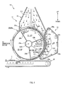
- Fig. 3 is an III-III cross sectional view of Fig. 1 .
- a manufacturing method of the absorbent body 1 according to a first embodiment is a manufacturing method of a thin absorbent body 1.
- the manufacturing method of the absorbent body 1 includes an absorbent body molding process that molds the absorbent body 1 by laminating pulp fiber 2 (corresponding to liquid absorbent fiber) including superabsorbent polymer 5, and an absorbent body thinning process that makes a lamination thickness of the molded absorbent body 1 thin while substantially maintaining a basis weight.
- the former absorbent body molding process is performed by a so-called fiber stacking apparatus 11, and further, in regards to the latter absorbent body thinning process, a thinning apparatus 51 arranged near the fiber stacking apparatus 11 is to perform the process in association with the fiber stacking apparatus 11.
- the fiber stacking apparatus 11 corresponds to a "first apparatus” and a "second apparatus”
- the thinning apparatus 51 corresponds to the "second apparatus”.
- the fiber stacking apparatus 11 and the thinning apparatus 51 are described.
- the fiber stacking apparatus 11 includes, for example, (1) a rotating drum 20 that drivingly rotates continuously in one direction of a circumferential direction Dc1 (for example, clockwise) with a horizontal shaft C20 as a rotational center, (2) a supply duct 31 that discharges and supplies mixed air 3 (corresponding to a gas), including pulp fiber 2, towards an outer circumferential face 20a of the rotating drum 20 from a supply opening 31a arranged in a predetermined position in the circumferential direction Dc1 of the rotating drum 20, (3) a polymer inserting duct 33 included in the supply duct 31 and that discharges the granular superabsorbent polymer 5 towards the outer circumferential face 20a, and (4) a suction conveyor 41 (corresponding to a mold-release mechanism) arranged on a downstream side in the circumferential direction Dc1 of the supply duct 31, and that sucks the absorbent body 1 in order to mold release it from a mold 21 on the outer circumferential face 20a of the rotating drum 20 and transports it.
- the circumferential direction Dc1 of the rotating drum 20 is merely referred to as the “circumferential direction Dc1", and a direction along the horizontal shaft C20 of the rotating drum 20 (a direction passing through a plane of paper in Fig. 1 ) is referred to as a "width direction Dw”. Note that this width direction Dw is perpendicular to the circumferential direction Dc1.
- the rotating drum 20 (corresponding to a moving member, and a first rotating drum) is a substantially cylindrical body, and on its outer circumferential face 20a is included, intermittently in a predetermined pitch in a circumferential direction Dc1, the molds 21 in a concave form corresponding to a form of the absorbent body 1 to be molded. Then, at a bottom section 21a of each mold 21 (corresponding to a placement surface) are provided a plurality of suction holes 22, and through these suction holes 22 an inner side of the mold 21 is in communication with an inner circumferential side of the rotating drum 20 in a permeable manner.
- a cylindrical division wall 24a concentrically with the rotating drum 20
- a doughnut shaped substantially closed space SP corresponding to a space
- this substantially closed space SP is zone divided in the circumferential direction Dc1 by a plurality of division walls 24b, 24b, 24b. Therefore, for example, a first zone Z1 shown in Fig.
- an air pressure P3 of a third zone Z3 on a further downstream side thereof is maintained at the same pressure as the outside air pressure or at an air pressure value in between the outside air pressure and an air pressure P1 of the first zone Z1.
- a supply opening 31a of the supply duct 31 is arranged, and on the other hand, the suction conveyor 41 is arranged in correspondence to the third zone Z3.
- a second zone Z2 positioned in between these first and third zones Z1, Z3 is related to the absorbent body thinning process and this will be described later.
- the absorbent body 1 is molded as follows. Firstly, by the driving rotation of the rotating drum 20, the mold 21 is moved along a path, along the outer circumferential face 20a, as a travel path. Then, when this mold 21 is passing the position of the supply duct 31, substantially only air of the mixed air 3 discharged and supplied from the supply opening 31a is sucked into the suction holes 22 on the bottom section 21a of the mold 21, and thus on the bottom section 21a are laminated the pulp fiber 2 and the superabsorbent polymer 5 in the mixed air 3 and the absorbent body 1 is manufactured.
- the absorbent body 1 in the mold 21 is sucked towards the outside by the suction air from the suction conveyor 41 and successively mold-released from the mold 21, and thereafter transported by the suction conveyor 41.
- the thinning apparatus 51 is to make a lamination thickness of the absorbent body 1 thin, and this apparatus 51 is arranged in a position between the supply duct 31 and the suction conveyor 41 in the circumferential direction Dc1 of the rotating drum 20 and opposing the outer circumferential face 20a of the rotating drum 20.
- the air pressure Pf2 in the space S in between the pulp fibers in the absorbent body 1 that has been laminated and molded in the mold 21 is made lower than the air pressure Pf1 in the space S in between the pulp fibers in the absorbent body 1 while laminating using the supply duct 31.
- the air in the space S in between the pulp fibers in the absorbent body 1 is sucked up to move the fibers 2 towards the bottom portion 21a so that the pulp fibers 2 become closely packed, from the state shown in Fig. 2A to the state shown in Fig. 2B , and the lamination thickness t1 of the absorbent body 1 is made thin.
- the space S in between the pulp fibers is only packed by the movement of the pulp fibers 2, and therefore the superabsorbent polymers 5 in the absorbent body 1 are generally not squashed, and their forms are maintained in a granular shape of the original form when injected into the mold 21. As a result, hardening and unevenness in hardness of the absorbent body 1 due to the thinning is effectively prevented.
- Such thinning apparatus 51 has a non-air permeable endless belt 53 (corresponding to a belt member) that moves in a predetermined circular orbit as a main body, and this endless belt 53 has a portion of its circular orbit arranged along a portion of the outer circumferential face 20a of the rotating drum 20 in an arc shape. Therefore, in a range A1 along this arc shape (hereinbelow, referred to as a belt setting range A1), the endless belt 53 covers the absorbent body 1 on a side opposite side from the bottom section 21a of the mold 21 by its flat outer circumferential face 53a, and moves together with the movement of the mold 21 in the circumferential direction Dc1 at substantially the same speed as the mold 21.
- the air suction amount from the suction holes 22 to maintain the air pressure Pf2 in the space S in between the pulp fibers to the above level can be made small, and thus, the necessary power of a blower, for example, for the suction of air, can be made small.
- a value of the air pressure P2 of the second zone Z2 is set as, for example, an air pressure value where an air pressure Pf2 of the space S in between the pulp fibers in the absorbent body 1 in a state where the mold 21 is covered by the endless belt 53 becomes lower than an air pressure Pf1 of the space S in between the pulp fibers in the absorbent body 1 at the time of lamination by the supply duct 31.
- the air pressure P2 of the second zone Z2 is set as the same pressure or a lower pressure than the air pressure P1 of the first zone.
- the reason that it can be the same pressure is because while laminating in the first zone Z1, the mixed air 3 is supplied into the supply duct 31, but in the second zone Z2, the mixed air 3 is not supplied, and inflow of the outside air into the absorbent body 1 can be suppressed by the endless belt 53.
- the second zone Z2 may be further subdivided into a plurality of zones in the circumferential direction Dc1 by a division wall 24c.
- it is subdivided into two zones Z2a, Z2b.
- an air pressure P2b of a zone Z2b corresponding to a downstream end E1 in the circumferential direction Dc1 of the belt setting range A1 may be set to a value in between the air pressure P2a of the zone Z2a adjacent to the upstream side thereof and an air pressure P3 of the third zone Z3 adjacent to the downstream side thereof.
- the zone Z2b corresponding to the downstream end E1 of the belt setting range A1 functions as a buffer zone in air pressure change, in other words, a sudden air pressure fluctuation that may occur when the mold 21 moves from the low air pressure second zone Z2 to the high air pressure third zone Z3 can be relieved, and dropping off or peeling off and the like of the absorbent body 1 from the mold 21 due to the suction air pressure fluctuation can be effectively prevented.
- a width W53 of the endless belt 53 is made wider than a size W21 of the width direction Dw of the mold 21 as shown in Fig. 3 .
- the endless belt 53 that has been sucked towards the outer circumferential face 20a by the suction air from the suction holes 22 of the mold 21, adopts a closely contacting state for each portion 20b, 20b at an outer side in the width direction Dw of the mold 21 on the outer circumferential face 20a (corresponding to a predetermined surface) of the rotating drum 20 (corresponding to a predetermined member) as shown in Fig. 3 . Therefore, inflow of the outside air from the width direction Dw is effectively prevented.
- a length in the circumferential direction Dc1 of the belt setting range A1 shown in Fig. 1 is set longer than an entire length L21 of the circumferential direction Dc1 of the mold 21, and more preferably, set longer than 1.5 times of the entire length L21. Then, the mold 21 in which the air in the space S in between the pulp fibers is being sucked up can be covered up by the endless belt 53 from all directions (all directions of the width direction Dw and the circumferential direction Dc1) of its four peripheral edges, and therefore outside air inflow into the absorbent body 1 can be almost completely prevented.
- a depth direction and a lamination thickness direction of the mold 21 are in the same direction. Therefore, preferably, a depth d21 of the bottom section 21a of the mold 21, with the outer circumferential face 20a of the rotating drum 20 as a reference, is set deeper than a target lamination thickness t1 of the absorbent body 1 while laminating by the supply duct 31. Then, in this process of the thinning apparatus 51, the endless belt 53 and the absorbent body 1 can be made to be in a substantially entirely non-contacting state. Therefore, sandwiching and pressing the absorbent body 1 physically with both the bottom portion 21a of the mold 21 and the endless belt 53 can be effectively avoided, and as a result squashing of the superabsorbent polymers can be further suppressed.
- a circular orbit of the endless belt 53 is formed by the endless belt 53 being put around a plurality of pass-line rollers 55a, 55b, 55c arranged in predetermined positions. Then, at least one of these pass-line rollers 55a, 55b, 55c is configured as a driving roller 55a connected to a driving source such as a motor. Therefore, by appropriately speed-controlling and the like the driving source, and drive-controlling the moving speed of the endless belt 53 in the belt setting range A1, with the moving speed of the mold 21 as a target speed, then the endless belt 53 and the mold 21 can be moved at substantially the same speed as each other as described above.
- the rollers 55c, 55c ... that are in charge of an orbit of the belt setting range A1 are guided movably in a separating direction in respect to the outer circumferential face 20a of the rotating drum 20 by appropriate guide members, and a pressing force is added in a pressing direction to the outer circumferential face 20a by an elastic member such as a spring.
- the endless belt 53 can be easily maintained in a surface contacting state to the outer circumferential face 20a of the rotating drum 20, and the airtightness in the mold 21 is increased (refer to Fig. 3 ). Further, a tension of the endless belt 53 can be easily maintained at a certain value, so that a running state of the endless belt 53 can also be stabilized.
- the circular orbit of the endless belt 53 may be set so that an end edge 31e at a downstream side in the circumferential direction Dc1 of the supply opening 31a of the supply duct 31 is covered over in the circumferential direction Dc1 by the endless belt 53.
- the outside air that enters into the supply duct 31 from a gap between the end edge 31e of the supply opening 31a and the outer circumferential face 20a of the rotating drum 20 can be suppressed, and lamination by the supply duct 31 can be stabilized.
- Fig. 4 is an explanatory diagram of a first modified example of the first embodiment and shows a central vertical cross sectional view of a manufacturing apparatus 10a that is used in the manufacturing method of the first modified example.
- an endless belt 53 that synchronizes with the rotation of the rotating drum 20 and moves around is illustrated as a covering member, but in this first modified example, in place of the endless belt 53, in the range corresponding to the above belt setting range A1, an immovable arc shaped plate member 51a as the covering member 51a is arranged opposing the outer circumferential face 20a of the rotating drum 20. Then, with this non-air permeable arc shaped plate member 51a, inflow of the outside air into the absorbent body 1 is suppressed.
- this arc shaped plate member 51a is immovable, it cannot be made to closely contact the outer circumferential surface 20a of the rotating drum 20, that is, it is a structure having a space G2 in between the plate member and the outer circumferential surface 20a of the rotating drum 20 and in which the outside air can easily flow from the space G2 into the absorbent body 1. Therefore, in comparison with the endless belt 53 in the above described first embodiment, the airtightness in the mold 21 is poor, and as a result it is also inferior in ability to make the absorbent body 1 thin.
- a contacting seal member such as a brush may be interposed to suppress inflow of the outside air into the absorbent body 1.
- Fig. 5 and Fig. 6 are explanatory views of a second modified example of the first embodiment.
- Fig. 5 is a central vertical cross sectional view of a manufacturing apparatus 10b used in a manufacturing method of the second modified example.
- Fig. 6 is a perspective view of a rotating drum 20g of a fiber stacking apparatus 11b included in the manufacturing apparatus 10b.
- the absorbent body 1 is intermittently molded in the circumferential direction Dc1 of the rotating drum 20, but this second modified example differs in that a continuous body 1a of the absorbent body is molded, the continuous body 1a of the absorbent body being made with the absorbent body 1 continuously in the circumferential direction Dc1.
- a single groove portion 21t that continues endlessly along the circumferential direction Dc1 is formed as the mold 21t. Then, at a bottom section 21a of this groove portion 21t, as shown in Fig.
- a plurality of suction hole 22 are provided over the entire circumference of the circumferential direction Dc1, and the pulp fiber 2 and the like are laminated in the groove portion 21t with suction air from these suction holes 22, and thus the continuous body 1a of the absorbent body is molded.
- Other parts are substantially the same as the above first embodiment.
- a width W53 of the endless belt 53 according to the above thinning apparatus 51 is made thinner than a width W21t of the groove portion 21t. Then, the endless belt 53 that has been sucked towards the groove portion 21t by the suction air from the suction holes 22 of the groove portion 21t can speedily enter into the groove portion 21t, and thus the continuous body 1a of the absorbent body is physically compressed in the lamination thickness direction by also a pressing force from the endless belt 53, and as a result the lamination thickness of the continuous body 1a can be made thinner.
- the width W53 of the endless belt 53 is preferably made thin in a range of 0.8 times to 0.9 times of the width W21t of the groove portion 21t.
- the width W53 of the endless belt 53 may be in a range of 0.9 to 1.3 times that of the width W21t of the groove portion 21t.
- a rubber endless belt 53 in the case of pressing the absorbent body 1 or its continuous body 1a with the endless belt 53 as described above, with a flexible elastic deformation of the endless belt 53, squashing of the superabsorbent polymers 5 that are harder than the pulp fibers 2 can be suppressed and, of the two, the pulp fiber 2 can be selectively compressed.
- a rubber endless belt 53 with a hardness of 35 to 40A in the notation of Shore A of ISO (International Organization for Standardization) may be used.
- Fig. 7 is a central vertical cross sectional view of an example of a manufacturing apparatus 10c to be used in a manufacturing method of a second embodiment.
- Fig. 8 is an enlarged view of a thinning apparatus 61 equipped in this manufacturing apparatus 10c.
- Fig. 9 is an IX-IX cross sectional view of Fig. 8 .
- the fiber stacking apparatus 11 bears a part of the absorbent body thinning process, but in this second embodiment, the fiber stacking apparatus 11 performs merely only the absorbent body molding process, and is generally not engaged in the absorbent body thinning process.
- the thinning apparatus 61 according to the second embodiment receives the absorbent body 1 molded by the fiber stacking apparatus 11, and thereafter, the thinning apparatus 61 makes the lamination thickness of the absorbent body 1 thin, while transporting the absorbent body 1.
- the fiber stacking apparatus 11 corresponds to the "first apparatus”
- the thinning apparatus 61 corresponds to the "second apparatus”.
- the transferring drum 63 to be described later according to the thinning apparatus 61 can be used as an apparatus dedicated to making the lamination thickness of the absorbent body 1 thin.
- the specification of a hole diameter of the suction holes 66, to be described later, on the outer circumferential face 63a of the transferring drum 63 and its arrangement pattern arrangement and the like can be designed as specifications specialized in making the lamination thickness thin.
- the fiber stacking apparatus 11 is a generally similar structure as in the first embodiment.
- the fiber stacking apparatus 11 has a rotating drum 20 (corresponding to a first rotating drum) that drivingly rotates in one direction of the circumferential direction Dc1 (for example anticlockwise) with a horizontal shaft C20 as a rotational center, and is arranged with a supply duct 31 in a predetermined position in the circumferential direction Dc1 of the rotating drum 20.
- a delivery position Qout1 for handing over the absorbent body 1 that has been molded in the mold 21 on the outer circumferential face 20a of the rotating drum 20 by the supply duct 31 to the thinning apparatus 61 is set. Note that, configurations that are the same as or similar to those in the first embodiment are denoted with the same figures and explanations are omitted.
- the thinning apparatus 61 also has a rotating drum 63 (hereinbelow, referred to as a transferring drum 63 (corresponding to a moving member, and a second rotating drum)).
- This transferring drum 63 is also a substantially cylindrical body, and drivingly rotates in one direction (for example, clockwise) in the circumferential direction Dc2 together with the rotating drum 20, with a shaft C63, that is parallel with the shaft C20 of the rotating drum 20 of the fiber stacking apparatus 11, as a rotational center. Further, this transferring drum 63 is arranged, at the above delivery position Qout1, with its outer circumferential face 63a opposing the outer circumferential face 20a of the rotating drum 20 of the fiber stacking apparatus 11.
- the absorbent body 1 on the outer circumferential face 20a of the rotating drum 20 is received on the outer circumferential face 63a of the transferring drum 63 and held on the outer circumferential face 63a.
- the absorbent body 1 is subject to a process to make its lamination thickness thin, in other words a thinning process, and thereafter, the absorbent body 1 is transported to the delivery position Qout2 in the circumferential direction Dc2, handed over to the suction conveyor 81 at the same position Qout2, and thereafter transported by the suction conveyor 81.
- the outer circumferential face 63a of the transferring drum 63 is formed as a substantially smooth surface, and on this outer circumferential face 63a is set intermittently in a predetermined pitch in the circumferential direction Dc2 a plurality of holding surfaces 64 (corresponding to a placement surface) to hold the received absorbent body 1.
- Each holding surface 64 is a smooth surface with an area corresponding to a planar size of the absorbent body 1, and each holding surface 64 is arranged with a plurality of the suction holes 66 in an appropriate arrangement pattern such as a grid arrangement or a staggered arrangement. Then, each holding surface 64 has an ability to retain the absorbent body 1 using the suction air from these suction holes 66.
- a suction air source of these suction holes 66 is a negative pressure space Z11 at the inner circumferential side of the transferring drum 63. More specifically, on the inner circumferential side of the transferring drum 63 is included a cylindrical division wall 67a concentrically with the transferring drum 63, and thus, on the inner circumferential side of the transferring drum 63 is defined a doughnut shaped substantially closed space SP63 (corresponding to a space). Further, this substantially closed space SP63 is zone divided in the circumferential direction Dc2 by a plurality of division walls 67b, 67b.
- the space is divided into two to form a first zone Z11 from a receiving position Qin2 to a delivery position Qout2, and a second zone Z22 from a delivery position Qout2 to a receiving position Qin2.
- the first zone Z11 is maintained in a negative pressure state at an air pressure lower than the outside air pressure, and thus, by the suction air from the suction holes 66 on the holding surface 64, the absorbent body 1 received at the receiving position Qin2 is adsorbed and held on the holding surface 64.
- the second zone Z22 is maintained at an air pressure that is the same as or slightly higher than the outside air pressure, and thus, handing over of the absorbent body 1 to the suction conveyor 81 at the delivery position Qout2 can be performed smoothly.
- an area of the thinning process to make the absorbent body 1 thin in the circumferential direction Dc2 of the transferring drum 63 is set in a range corresponding to the first zone Z11.
- a non-air permeable rubber endless belt 73 (corresponding to a belt member) that moves in a predetermined circular orbit. More specifically, this endless belt 73 is arranged with a portion of its circular orbit in an arc shape along the outer circumferential face 63a of the transferring drum 63.
- the endless belt 73 covers the absorbent body 1 from a side opposite to the holding surface 64 of the transferring drum 63 with its even outer circumferential face 73a and moves at substantially the same speed as the holding surface 64 in the circumferential direction Dc2 together with the movement of the holding surface 64.
- suction of air from the suction holes 66 in this belt setting range A2 is performed based on the air pressure P11 in the above first zone Z11.
- the value of the air pressure P11 of the first zone Z11 is set as, for example, an air pressure value in which the air pressure Pf4 in the space S in between the pulp fibers in the absorbent body 1, that is in a state in which the absorbent body 1 on the holding surface 64 is covered by the endless belt 73, is lower than the air pressure Pf1 in the space S in between the pulp fibers in the absorbent body 1 while laminating by the fiber stacking apparatus 11.
- the first zone Z11 may be further subdivided into a plurality of zones in the circumferential direction Dc2 by the dividing walls 67c.
- it is subdivided into three zones ⁇ , ⁇ , and ZB. That is, first, it is divided into an upstream zone ZA substantially corresponding to the above belt setting range A2 and a downstream zone ZB on a downstream side in the circumferential direction Dc2, and further, in regards to the former upstream zone ZA, it is divided into a zone ⁇ in the circumferential direction Dc2 and a zone ⁇ in the downstream side thereof.
- the air pressure P ⁇ of the zone ⁇ may be set to an air pressure value in between the air pressure P ⁇ in the zone ⁇ and the air pressure Pb in the downstream zone ZB.
- the zone ⁇ corresponding to the downstream end E2 of the belt setting range A2 functions as a buffer zone for air pressure change, that is a rapid air suction pressure fluctuation that may occur in the case where the holding surface 64 moves from the low air pressure upstream zone ZA to the high air pressure downstream zone ZB can be relieved, and falling off or peeling off of the absorbent body 1 from the holding surface 64 due to this suction air pressure fluctuation can be effectively prevented.
- the outer circumferential face 63a of this transferring drum 63 is formed as a substantially smooth surface without a concave portion deeper than the lamination thickness t1 of the absorbent body 1 at the time it is received from the fiber stacking apparatus 11, and therefore the absorbent body 1 is held on the holding surface 64 in a state protruding from the outer circumferential face 63a.
- the endless belt 73 that has been sucked towards the outer circumferential face 63a by the suction air from the suction holes 66 on the holding surface 64, can sandwich and press the absorbent body 1 with the holding surface 64 on the outer circumferential face 63a of the transferring drum 63, and therefore the absorbent body 1 can be made thinner.
- the endless belt 73 with its flexible elastic deformation due to it being manufactured by rubber, can suppress squashing of the superabsorbent polymer 5 that is harder than the pulp fiber 2 and, of the two, selectively compress the pulp fibers 2.
- a rubber endless belt 73 with a hardness of 35 to 40A in the notation of Shore A of ISO (International Organization for Standardization) is preferably used, as described above.
- a width W73 of the endless belt 73 is made wider than a size W64 in the width direction Dw of the holding surface 64 as shown in Fig. 9 . Then, the endless belt 73 that has been sucked towards the outer circumferential face 63a by the suction air from the suction holes 66 on the holding surface 64, adopts a closely contacting state for each portion 63b, 63b at the outer side in the width direction Dw of the holding surface 64 on the outer circumferential face 63a (corresponding to a predetermined surface) of the transferring drum 63 (corresponding to a predetermined member) as shown in Fig.
- a length in the circumferential direction Dc2 of the belt setting range A2 is set longer than an entire length L64 in the circumferential direction Dc2 of the holding surface 64 as shown in Fig. 8 .
- the holding surface 64 which is sucking up the air in the space S in between the pulp fibers can be covered by the endless belt 73 from all directions of its four peripheral edges (all directions of the width direction Dw and the circumferential direction Dc2), and therefore inflow of the outside air into the absorbent body 1 can be completely prevented.
- the suction holes 66 may be formed in respect of each portion 63b, 63b on the outer side of the outer circumferential face 63a (referred to as a chain double-dashed line), and in this way the degree of close contact of the endless belt 73 and each portion 63b, 63b on the outer side can be further increased.
- the circular orbit of the endless belt 73 is formed by putting the endless belt 73 around a plurality of pass-line rollers 75a, 75b, 75c arranged in predetermined positions, and at least one of these pass-line rollers 75a, 75b, 75c is configured as a driving roller 75a that has been connected to a driving source such as a motor. Therefore, by appropriate speed controlling and the like of the driving source, with the moving speed of the holding surface 64 as a target speed, when the moving speed of the endless belt 73 in the belt setting range A2 is drive controlled, as described above, the endless belt 73 and the holding surface 64 can be moved at substantially the same speed as each other.
- these pass-line rollers 75a, 75b, 75c in respect to the rollers 75c, 75c ... that are in charge of the orbit in the belt setting range A2, in other words, the rollers 75c, 75c ... that are in charge of an arc shaped orbit along the outer circumferential face 63a of the transferring drum 63, are guided movably in a separating direction in respect to the outer circumferential face 63a of the transferring drum 63 by appropriate guide members, and a pressing force is added in a pressing direction to the outer circumferential face 63a by an elastic member such as a spring. Then, with the pressing force, the endless belt 73 is pressed against the outer circumferential face 63a of the transferring drum 63, so that airtightness in the absorbent body 1 and a pressing force on the absorbent body 1 can be increased.
- the entire circular orbit of this endless belt 73 may be surrounded by a non-air permeable box member 77.
- the box member 77 in which only a surface opposing the outer circumferential face 63a of the transferring drum 63 is open, is used. Then, in this way, outside air inflow into the absorbent body 1 can be more effectively suppressed.
- an immovable covering member in place of the endless belt 73, in a range that corresponds to the belt setting range A2, an immovable covering member, not shown, may be arranged opposing the outer circumferential face 63a of the transferring drum 63, and thus inflow of the outside air into the absorbent body 1 may be suppressed.
- the rotating drum 20g according to the second modified example of the first embodiment may be applied, and thus the lamination thickness in respect to the continuous body 1a of the absorbent body can be made thin.
- a groove portion (not shown) that can accommodate the absorbent body 1 may be provided to accommodate the absorbent body 1 in the groove portion. Then, the absorbent body 1, in which the air in the space S in between the pulp fibers is being sucked up, and the endless belt 73 can be made to be in a non-contacting state, and, as a result, squashing of the superabsorbent polymers 5 in the absorbent body 1 can be suppressed.
- endless belts 53, 73 those made of rubber are illustrated, but in some cases those made of resin or metal may be used.
- the covering member the non-air permeable endless belts 53, 73, the non-air permeable arc shaped plate member 51a and the like are illustrated, but they may have slight air permeability.
- the covering member may have some air permeability.
- the belt member has no air permeability.
- the endless belt 53 with a flat outer circumferential face 53a is illustrated, however it is not limited thereto.
- an endless belt may be used in which at least a portion that is to come into contact with the outer circumferential face 20a of the rotating drum 20 is flat, and further an endless belt with the outer circumferential face 53a that is not flat may be used.
- a flat face is preferable however, because each portion in the outer circumferential face 53a can closely contact with the corresponding portion, and the airtightness in the absorbent body 1 can be increased.
- the endless belt 73 with a flat outer circumferential face 73a is illustrated, but for example, an endless belt may be used in which at least a portion in the endless belt 73 that is to come into contact with the absorbent body 1, and/or a portion in the endless belt 73 that is to come into contact with the outer circumferential face 63a of transferring drum 63, is flat, and further an endless belt with the outer circumferential face 73a that is not flat may be used.
- a flat face is preferable since each portion in the outer circumferential face 73a closely contacts the corresponding portion and can increase the airtightness in the absorbent body 1.
- an air permeable continuous sheet such as a tissue paper or a nonwoven fabric was not wrapped around the outer circumferential face 20a of the rotating drums 20, 20g of the fiber stacking apparatuses 11, 11b, but it is not limited thereto.
- a continuous sheet may be wrapped around in a predetermined wrap-around angle and the continuous sheet may be transported by rotation of the rotating drums 20, 20g, and when the continuous sheet passes the position on the supply duct 31, the absorbent body 1 may be laminated on the continuous sheet.
- the second embodiment Fig.
- the continuous sheet is transported from the fiber stacking apparatus 11 to the transferring drum 63 integrally with the absorbent body 1, and at the transferring drum 63 the continuous sheet is positioned closer to the endless belt 73 side than the absorbent body 1. Therefore, by the suction air from the suction holes 66 on the outer circumferential face 63a of the transferring drum 63, when the continuous sheet is sucked toward the transferring drum 63, this continuous sheet can forcibly press the absorbent body 1, thus the absorbent body 1 can be made further thinner.
- the continuous sheet is a tissue paper or a nonwoven fabric and the like, and has flexibility, and also functions as a buffer material that relieves the pressing force of the endless belt 73 and transfers it to the absorbent body 1, and thus squashing of the superabsorbent polymer 5 in the absorbent body 1 is suppressed.
- the rotating drums 20, 20g were used as the fiber stacking apparatuses 11, 11b, but it is not limited thereto.
- the mold 21 may be formed in a concave shape on the belt of the belt conveyor, the suction holes 22 may be included on the bottom section 21a of the mold 21, and the belt may be moved in a predetermined orbit, and the supply duct 31 and the like may be arranged in a predetermined position on that orbit.
- the transferring drum 63 in other words the rotating drum 63, was used, but it is not limited thereto.
- the holding surface 64 may be provided on the surface of the belt of the belt conveyor, and the suction holes 66 may be provided on the holding surface 64, and the belt may be moved in the predetermined orbit, then over the predetermined range on that orbit, the endless belt 73 may be arranged so as to cover the absorbent body 1 that is being held on the holding surface 64.
- air is illustrated as an example of the gas to be discharged and supplied from the supply duct 31, but it is not limited thereto as long as it is a gas that can include, mixed therein, a liquid absorbent fiber such as the pulp fiber 2 and the superabsorbent polymer 5 and that does not chemically react or the like with the fiber and the superabsorbent polymer 5, and it may be a gas such as nitrogen.
- the pulp fiber 2 (a pulp that has been pulverized into a fibrous state) is illustrated as the liquid absorbent fiber, but cellulose such as cotton, regenerated cellulose such as rayon and fibril rayon, semisynthetic cellulose such as acetate and triacetate, fibrous polymer, thermoplastic fiber, or a combination of the above may be used.
- 1 absorbent body 1a continuous body of absorbent body (absorbent body), 2 pulp fiber (liquid absorbent fiber), 3 mixed air (gas), 5 superabsorbent polymer, 10 manufacturing apparatus, 10a manufacturing apparatus, 10b manufacturing apparatus, 10c manufacturing apparatus, 11 fiber stacking apparatus (first apparatus, second apparatus), 11b fiber stacking apparatus (first apparatus, second apparatus), 20 rotating drum (moving member, first rotating drum, predetermined member), 20a outer circumferential face (predetermined surface), 20b portion, 20g rotating drum (moving member, first rotating drum, predetermined member), 21 mold, 21a bottom section (placement surface), 21t groove portion (mold), 22 suction hole, 24a cylindrical division wall, 24b division wall, 24c division wall, 31 supply duct, 31a supply opening, 31e end edge, 33 polymer inserting duct, 41 suction conveyor (mold-release mechanism), 51 thinning apparatus (second apparatus), 51a arc shaped plate member (covering member), 53 endless belt (belt member, covering member), 53a outer circumferential face, 55a
Landscapes
- Health & Medical Sciences (AREA)
- Engineering & Computer Science (AREA)
- Life Sciences & Earth Sciences (AREA)
- Biomedical Technology (AREA)
- Heart & Thoracic Surgery (AREA)
- Vascular Medicine (AREA)
- Epidemiology (AREA)
- Animal Behavior & Ethology (AREA)
- General Health & Medical Sciences (AREA)
- Public Health (AREA)
- Veterinary Medicine (AREA)
- Manufacturing & Machinery (AREA)
- Mechanical Engineering (AREA)
- Absorbent Articles And Supports Therefor (AREA)
Applications Claiming Priority (2)
| Application Number | Priority Date | Filing Date | Title |
|---|---|---|---|
| JP2009240707A JP5581034B2 (ja) | 2009-10-19 | 2009-10-19 | 吸収体の製造方法、及び製造装置 |
| PCT/JP2010/067736 WO2011048964A1 (fr) | 2009-10-19 | 2010-10-08 | Procédé et dispositif pour fabriquer un corps d'absorption |
Publications (2)
| Publication Number | Publication Date |
|---|---|
| EP2491908A1 true EP2491908A1 (fr) | 2012-08-29 |
| EP2491908A4 EP2491908A4 (fr) | 2013-03-13 |
Family
ID=43900193
Family Applications (1)
| Application Number | Title | Priority Date | Filing Date |
|---|---|---|---|
| EP10824813A Withdrawn EP2491908A4 (fr) | 2009-10-19 | 2010-10-08 | Procédé et dispositif pour fabriquer un corps d'absorption |
Country Status (8)
| Country | Link |
|---|---|
| US (2) | US9248608B2 (fr) |
| EP (1) | EP2491908A4 (fr) |
| JP (1) | JP5581034B2 (fr) |
| KR (1) | KR101582715B1 (fr) |
| CN (1) | CN102573733B (fr) |
| AR (1) | AR078700A1 (fr) |
| TW (1) | TWI519287B (fr) |
| WO (1) | WO2011048964A1 (fr) |
Cited By (4)
| Publication number | Priority date | Publication date | Assignee | Title |
|---|---|---|---|---|
| EP2308432A4 (fr) * | 2008-07-31 | 2013-09-25 | Uni Charm Corp | Dispositif et procede de fabrication d'un corps absorbant |
| EP2719364A1 (fr) * | 2012-10-09 | 2014-04-16 | Livedo Corporation | Appareil d'alimentation de particules, procédé de commande dudit appareil et procédé d'acquisition d'informations de détermination de vitesse |
| WO2015193332A1 (fr) * | 2014-06-16 | 2015-12-23 | Fmcg Consulting Ltd | Applicateur de particules de polymère super-absorbant à vitesse élevée |
| CN114126559A (zh) * | 2019-07-03 | 2022-03-01 | 株式会社瑞光 | 吸收体的制造方法和吸收性物品 |
Families Citing this family (29)
| Publication number | Priority date | Publication date | Assignee | Title |
|---|---|---|---|---|
| US9550306B2 (en) | 2007-02-21 | 2017-01-24 | Curt G. Joa, Inc. | Single transfer insert placement and apparatus with cross-direction insert placement control |
| US9944487B2 (en) | 2007-02-21 | 2018-04-17 | Curt G. Joa, Inc. | Single transfer insert placement method and apparatus |
| US9089453B2 (en) | 2009-12-30 | 2015-07-28 | Curt G. Joa, Inc. | Method for producing absorbent article with stretch film side panel and application of intermittent discrete components of an absorbent article |
| ITBO20110186A1 (it) * | 2011-04-08 | 2012-10-09 | Gdm Spa | Metodo e unità per la realizzazione di imbottiture per articoli assorbenti igienici. |
| JP6005916B2 (ja) * | 2011-08-29 | 2016-10-12 | ユニ・チャーム株式会社 | 吸収性物品の製造方法 |
| US10828204B2 (en) * | 2011-09-08 | 2020-11-10 | Curt G. Joa, Inc. | Apparatus and method for forming absorbent cores |
| CA2807809C (fr) | 2012-02-20 | 2019-07-23 | Curt G. Joa, Inc. | Methode de formation de liaisons entre des composants discrets d'articles jetables |
| US9908739B2 (en) | 2012-04-24 | 2018-03-06 | Curt G. Joa, Inc. | Apparatus and method for applying parallel flared elastics to disposable products and disposable products containing parallel flared elastics |
| JP6045302B2 (ja) * | 2012-10-31 | 2016-12-14 | ユニ・チャーム株式会社 | 体液処理用の吸収体の製造方法 |
| US9283683B2 (en) | 2013-07-24 | 2016-03-15 | Curt G. Joa, Inc. | Ventilated vacuum commutation structures |
| USD704237S1 (en) | 2013-08-23 | 2014-05-06 | Curt G. Joa, Inc. | Ventilated vacuum commutation structure |
| USD703712S1 (en) | 2013-08-23 | 2014-04-29 | Curt G. Joa, Inc. | Ventilated vacuum commutation structure |
| USD703247S1 (en) | 2013-08-23 | 2014-04-22 | Curt G. Joa, Inc. | Ventilated vacuum commutation structure |
| USD703248S1 (en) | 2013-08-23 | 2014-04-22 | Curt G. Joa, Inc. | Ventilated vacuum commutation structure |
| USD703711S1 (en) | 2013-08-23 | 2014-04-29 | Curt G. Joa, Inc. | Ventilated vacuum communication structure |
| US9289329B1 (en) | 2013-12-05 | 2016-03-22 | Curt G. Joa, Inc. | Method for producing pant type diapers |
| JP6255232B2 (ja) * | 2013-12-12 | 2017-12-27 | 花王株式会社 | 吸収体の製造装置 |
| PL3325387T3 (pl) | 2015-07-24 | 2022-06-20 | Curt G. Joa, Inc. | Urządzenie do komutacji próżniowej oraz sposoby |
| US11376167B2 (en) | 2015-08-12 | 2022-07-05 | Sumitomo Seika Chemicals Co., Ltd. | Apparatus for manufacturing absorbent body |
| JP6720449B2 (ja) | 2015-08-12 | 2020-07-08 | 住友精化株式会社 | 吸収体の製造方法 |
| US9956579B2 (en) * | 2015-10-26 | 2018-05-01 | Iko Industries Ltd. | Device for dispensing granular roofing media on a moving sheet in a pattern |
| CN105395320B (zh) * | 2015-12-31 | 2016-09-28 | 北京倍舒特妇幼用品有限公司 | 一种制造模轮层流混合吸收芯的设备及其方法 |
| US11241711B2 (en) | 2017-03-22 | 2022-02-08 | 3M Innovative Properties Company | Buff-coated article and method of making the same |
| JP7027103B2 (ja) * | 2017-10-03 | 2022-03-01 | 花王株式会社 | 吸収体の製造方法及び吸収体の製造装置 |
| US11191675B2 (en) | 2017-10-03 | 2021-12-07 | Kao Corporation | Method for manufacturing absorbent body and device for manufacturing absorbent body |
| MX2020008306A (es) | 2018-02-28 | 2020-12-07 | Kimberly Clark Co | Nucleos absorbentes multicapa y metodos de fabricacion. |
| CN109847490B (zh) * | 2019-03-20 | 2024-07-12 | 中国石油大学(北京) | 一种刚性气液聚结滤芯、其制备方法及装置 |
| NL2025218B1 (en) * | 2020-03-26 | 2021-10-20 | Marel Further Proc Bv | System for moulding comprising a mould member, a method for moulding and a method for configuring a mould member |
| WO2022205579A1 (fr) * | 2021-03-29 | 2022-10-06 | 上海智联精工机械有限公司 | Dispositif de démoulage flexible, dispositif de moulage de noyau et procédé de formation de noyau |
Family Cites Families (20)
| Publication number | Priority date | Publication date | Assignee | Title |
|---|---|---|---|---|
| IT1034836B (it) | 1975-04-04 | 1979-10-10 | Fameccanica Spa | Procedimento macchina e relativi prodotti ottenuti nel settore igienico |
| DE3413925A1 (de) * | 1984-04-13 | 1985-10-24 | Winkler & Dünnebier, Maschinenfabrik und Eisengießerei GmbH & Co KG, 5450 Neuwied | Vorrichtung zur herstellung von saugkissen zum absorbieren von koerperfluessigkeit |
| ATE82597T1 (de) * | 1985-12-10 | 1992-12-15 | Kimberly Clark Co | Vorrichtung und verfahren fuer die erzeugung eines faservlieses. |
| JPH07114784B2 (ja) * | 1986-12-02 | 1995-12-13 | 株式会社瑞光 | 衛生用吸収成形体製造装置 |
| JP3408086B2 (ja) * | 1996-11-15 | 2003-05-19 | 花王株式会社 | 吸収性物品の製造装置 |
| JP4152049B2 (ja) * | 1999-12-22 | 2008-09-17 | 花王株式会社 | 粒子堆積体の製造方法 |
| US6330735B1 (en) * | 2001-02-16 | 2001-12-18 | Kimberly-Clark Worldwide, Inc. | Apparatus and process for forming a laid fibrous web with enhanced basis weight capability |
| SE520009C2 (sv) | 2001-09-17 | 2003-05-06 | Sca Hygiene Prod Ab | Förfarande och anordning för komprimering av fiberkroppar |
| US6982052B2 (en) * | 2002-09-26 | 2006-01-03 | Kimberly-Clark Worldwide, Inc. | Process and apparatus for air forming an article having a plurality of superimposed fibrous layers |
| EP1621166B2 (fr) | 2004-07-28 | 2018-11-28 | The Procter and Gamble Company | Procede de fabrication de parties centrales absorbantes |
| EP2238953B1 (fr) * | 2004-07-28 | 2013-06-19 | The Procter and Gamble Company | Impression indirecte d'AGM |
| DE602004026566D1 (de) * | 2004-07-28 | 2010-05-27 | Procter & Gamble | Indirekter Druck von AMG |
| JP4580736B2 (ja) * | 2004-11-18 | 2010-11-17 | ユニ・チャーム株式会社 | 吸液性芯材成型ドラム |
| JP4974522B2 (ja) * | 2005-12-26 | 2012-07-11 | 大王製紙株式会社 | 吸収体の製造装置 |
| JP2008132055A (ja) | 2006-11-27 | 2008-06-12 | Kao Corp | 吸収体 |
| JP4711945B2 (ja) | 2006-12-22 | 2011-06-29 | 花王株式会社 | 吸収体の製造方法及び製造装置 |
| JP5019906B2 (ja) | 2007-02-23 | 2012-09-05 | 花王株式会社 | 吸収体の製造方法 |
| JP4905973B2 (ja) * | 2007-03-20 | 2012-03-28 | 花王株式会社 | 吸引装置、シートの搬送方法、吸収体の製造方法及び不織布の嵩回復方法 |
| JP5227621B2 (ja) * | 2008-03-17 | 2013-07-03 | ユニ・チャーム株式会社 | 吸収体の製造装置及び製造方法 |
| US8307478B2 (en) * | 2009-09-29 | 2012-11-13 | MediGlider Corp. | Disposable comfort sheet |
-
2009
- 2009-10-19 JP JP2009240707A patent/JP5581034B2/ja active Active
-
2010
- 2010-10-08 EP EP10824813A patent/EP2491908A4/fr not_active Withdrawn
- 2010-10-08 KR KR1020127012774A patent/KR101582715B1/ko not_active Expired - Fee Related
- 2010-10-08 CN CN201080047082.5A patent/CN102573733B/zh not_active Expired - Fee Related
- 2010-10-08 WO PCT/JP2010/067736 patent/WO2011048964A1/fr not_active Ceased
- 2010-10-08 US US13/501,336 patent/US9248608B2/en not_active Expired - Fee Related
- 2010-10-18 AR ARP100103797A patent/AR078700A1/es unknown
- 2010-10-19 TW TW099135585A patent/TWI519287B/zh not_active IP Right Cessation
-
2012
- 2012-11-28 US US13/687,431 patent/US20130087289A1/en not_active Abandoned
Cited By (8)
| Publication number | Priority date | Publication date | Assignee | Title |
|---|---|---|---|---|
| EP2308432A4 (fr) * | 2008-07-31 | 2013-09-25 | Uni Charm Corp | Dispositif et procede de fabrication d'un corps absorbant |
| US8960122B2 (en) | 2008-07-31 | 2015-02-24 | Uni-Charm Corporation | Apparatus and method for manufacturing absorbent body |
| EP2719364A1 (fr) * | 2012-10-09 | 2014-04-16 | Livedo Corporation | Appareil d'alimentation de particules, procédé de commande dudit appareil et procédé d'acquisition d'informations de détermination de vitesse |
| US9186692B2 (en) | 2012-10-09 | 2015-11-17 | Livedo Corporation | Particle supplying apparatus, method of controlling particle supplying apparatus, and method of acquiring speed determining information |
| WO2015193332A1 (fr) * | 2014-06-16 | 2015-12-23 | Fmcg Consulting Ltd | Applicateur de particules de polymère super-absorbant à vitesse élevée |
| US11464679B2 (en) | 2014-06-16 | 2022-10-11 | Fmcg Consulting | High speed SAP particle applicator |
| CN114126559A (zh) * | 2019-07-03 | 2022-03-01 | 株式会社瑞光 | 吸收体的制造方法和吸收性物品 |
| CN114126559B (zh) * | 2019-07-03 | 2023-03-28 | 株式会社瑞光 | 吸收体的制造方法和吸收性物品 |
Also Published As
| Publication number | Publication date |
|---|---|
| KR101582715B1 (ko) | 2016-01-05 |
| CN102573733A (zh) | 2012-07-11 |
| TWI519287B (zh) | 2016-02-01 |
| JP2011083545A (ja) | 2011-04-28 |
| AR078700A1 (es) | 2011-11-30 |
| JP5581034B2 (ja) | 2014-08-27 |
| US20130087289A1 (en) | 2013-04-11 |
| CN102573733B (zh) | 2014-07-23 |
| WO2011048964A1 (fr) | 2011-04-28 |
| TW201124120A (en) | 2011-07-16 |
| US20120312463A1 (en) | 2012-12-13 |
| KR20120084310A (ko) | 2012-07-27 |
| EP2491908A4 (fr) | 2013-03-13 |
| US9248608B2 (en) | 2016-02-02 |
Similar Documents
| Publication | Publication Date | Title |
|---|---|---|
| EP2491908A1 (fr) | Procédé et dispositif pour fabriquer un corps d'absorption | |
| US9308132B2 (en) | Method and device for manufacturing composite sheet | |
| JP3172966U (ja) | おしめ/おむつで使用される吸水性パッドを形成するユニット | |
| CN103282002B (zh) | 用于一次性穿用物品的吸收性层及其制造方法 | |
| EP2581067B1 (fr) | Procédé de production d'un produit absorbant | |
| CN203483582U (zh) | 吸收性物品 | |
| RU2744188C1 (ru) | Упаковка впитывающего изделия и способ изготовления упаковки впитывающего изделия | |
| RU2598564C2 (ru) | Впитывающее изделие | |
| EP2491907A1 (fr) | Procédé et dispositif pour réduire l'épaisseur d'un corps d'absorption | |
| JP5723859B2 (ja) | 吸収性物品に係る吸収体の製造装置、及び製造方法 | |
| US9617105B2 (en) | Wrinkle smoothing method for a composite body of a continuous sheet related to absorbent articles | |
| EP0479442A1 (fr) | Procédé et dispositif de fabrication d'un produit composite | |
| US20120325620A1 (en) | Laminated product treating apparatus | |
| US11850129B2 (en) | Apparatus and method for manufacturing absorbent core used in disposable wearable article | |
| JP2968116B2 (ja) | 吸収体の積繊装置 | |
| JPH04161153A (ja) | 繊維の積繊方法及びその装置 | |
| JP6819744B2 (ja) | 吸収性物品の製造方法および製造装置 | |
| JP6819745B2 (ja) | 吸収性物品の製造方法および製造装置 |
Legal Events
| Date | Code | Title | Description |
|---|---|---|---|
| PUAI | Public reference made under article 153(3) epc to a published international application that has entered the european phase |
Free format text: ORIGINAL CODE: 0009012 |
|
| 17P | Request for examination filed |
Effective date: 20120323 |
|
| AK | Designated contracting states |
Kind code of ref document: A1 Designated state(s): AL AT BE BG CH CY CZ DE DK EE ES FI FR GB GR HR HU IE IS IT LI LT LU LV MC MK MT NL NO PL PT RO RS SE SI SK SM TR |
|
| DAX | Request for extension of the european patent (deleted) | ||
| A4 | Supplementary search report drawn up and despatched |
Effective date: 20130211 |
|
| RIC1 | Information provided on ipc code assigned before grant |
Ipc: A61F 13/49 20060101ALI20130205BHEP Ipc: A61F 13/15 20060101AFI20130205BHEP |
|
| 17Q | First examination report despatched |
Effective date: 20160414 |
|
| STAA | Information on the status of an ep patent application or granted ep patent |
Free format text: STATUS: THE APPLICATION IS DEEMED TO BE WITHDRAWN |
|
| 18D | Application deemed to be withdrawn |
Effective date: 20170801 |