EP2490191A2 - Halter für Anhaltekelle - Google Patents
Halter für Anhaltekelle Download PDFInfo
- Publication number
- EP2490191A2 EP2490191A2 EP12000936A EP12000936A EP2490191A2 EP 2490191 A2 EP2490191 A2 EP 2490191A2 EP 12000936 A EP12000936 A EP 12000936A EP 12000936 A EP12000936 A EP 12000936A EP 2490191 A2 EP2490191 A2 EP 2490191A2
- Authority
- EP
- European Patent Office
- Prior art keywords
- holder
- stopping
- receiving tray
- tiller
- trowel
- Prior art date
- Legal status (The legal status is an assumption and is not a legal conclusion. Google has not performed a legal analysis and makes no representation as to the accuracy of the status listed.)
- Granted
Links
- 230000011664 signaling Effects 0.000 title 1
- 239000004743 Polypropylene Substances 0.000 claims abstract description 3
- -1 polypropylene Polymers 0.000 claims abstract description 3
- 229920001155 polypropylene Polymers 0.000 claims abstract description 3
- 238000003466 welding Methods 0.000 claims description 3
- 230000006378 damage Effects 0.000 description 8
- 238000003860 storage Methods 0.000 description 7
- 238000004519 manufacturing process Methods 0.000 description 3
- 208000027418 Wounds and injury Diseases 0.000 description 2
- 208000014674 injury Diseases 0.000 description 2
- 238000004026 adhesive bonding Methods 0.000 description 1
- 210000003423 ankle Anatomy 0.000 description 1
- 239000006260 foam Substances 0.000 description 1
- 210000003127 knee Anatomy 0.000 description 1
- 210000002414 leg Anatomy 0.000 description 1
- 239000004033 plastic Substances 0.000 description 1
Images


Classifications
-
- G—PHYSICS
- G08—SIGNALLING
- G08B—SIGNALLING OR CALLING SYSTEMS; ORDER TELEGRAPHS; ALARM SYSTEMS
- G08B5/00—Visible signalling systems, e.g. personal calling systems, remote indication of seats occupied
- G08B5/006—Portable traffic signalling devices
Definitions
- the invention relates to a holder for a stopping trowel.
- Stopping scoops are used, for example, by the traffic police to wave individual vehicles out of a flowing stream of vehicles. This is usually done while driving by an officer sitting in the passenger seat holding the tiller from the open passenger window and so the driver behind him or obliquely next to him driving vehicle means to follow him, stop or at the next option, for example, a highway to leave.
- a tiller In order for such a tiller to be readily and easily accessible to officers, it is typically stored in a side storage compartment in the passenger door or center console. These compartments are not specially equipped for receiving such a tiller, but are generally provided as storage compartments for a variety of items and usually have no cover. The trowel is therefore only loose in the interior of the vehicle.
- a loose lying in the storage compartment trowel is the movement of the motor vehicle, for example when cornering, braking and accelerating or driving over an obstacle or a pothole in the receiving container tossed back and forth.
- On the one hand there is a considerable noise development, which permanently disturbs the vehicle occupants, and on the other hand damage to the stopping tine in the form of scratches or broken off sections.
- a trowel lying only loosely in a container can leave the container unhindered in the event of an accident and be thrown through the interior of the motor vehicle. In this case, it represents a considerable risk of injury to persons in the vehicle. This is particularly to be feared in the case of accidents in which the vehicle in which the trowel is stored overtops.
- the invention is therefore based on the object to propose a stowage possibility for a tiller in the interior of a motor vehicle in which the tiller is stowed firmly and safely and yet easily accessible.
- the invention solves this problem by a holder for a stop wedges with a mountable in the interior of a motor vehicle holding plate, arranged on the holding plate receiving tray and a clamping device for clamping the tiller in a transport position.
- the retaining plate of the holder according to the invention for example, on the inside of the passenger door of the motor vehicle can be fastened.
- the retaining plate is attached, for example via screws, rivets or the like at the respective position in the interior of the motor vehicle.
- the retaining plate can also be glued or fastened in any other way.
- the stopping trowel can then be introduced into the clamping device and is held in this in the transport position.
- the tiller is fixed and can not be thrown through the interior even in extreme maneuvers or accidents.
- the tiller is fixed and can not be thrown through the interior even in extreme maneuvers or accidents.
- the tiller is fixed and can not be thrown through the interior even in extreme maneuvers or accidents.
- the tiller is easy to stow the tiller easily and quickly by simply pinching and just as easy to remove the holder or the clamping device again.
- flying around during Normal driving maneuver is reliably prevented by the holder according to the invention, so that it can not cause rattling or damage to the tiller while
- the clamping device comprises at least one spring element, which is arranged such that the stopping tiller can be clamped between the at least one spring element and the receiving tray.
- the spring element is pressed out of the equilibrium position during the clamping of the tiller and thus spring-loaded by the spring force.
- the receiving cell, which is clamped between the at least one spring element and the receiving tray, is thus held in the transport position by this spring force.
- the equilibrium position of the at least one spring element is understood below to mean the position in which the at least one spring element is located when there is no stopping tine in the holder. In this position, the spring element may well exert a force on the other component of the clamping device. The at least one spring element would be biased in this case, so that the force exerted on the stopping tine force is greater than if the spring element would not be biased. As a result, the holding force is increased and thus increases the stability of the storage of the trowel in the holder.
- the clamping device may also comprise two spring elements, which are arranged such that the stopping tiller can be clamped between the two spring elements.
- the principle of action is identical.
- the two spring elements are moved from the equilibrium position and thus spring-loaded in the opposite direction in this embodiment. This creates a clamping action that holds the tiller in the transport position within the clamping device.
- the spring elements can preferably be riveted to the holding plate or the receiving tray.
- Other ways of attachment such as gluing or screwing possible.
- the clamping device is formed by the holding plate and at least a portion of the receiving tray. It is then no separate spring element necessary, whereby the production cost and thus the manufacturing cost can be reduced.
- the receiving tray is designed in this case so that the stopping tiller can be clamped between the holding plate and the receiving tray.
- at least a part of the receiving tray is preferably configured resiliently.
- the spring elements and at least one side of the receiving tray are equipped with a padding.
- a padding is particularly advantageously, at least a part of the retaining plate is provided with the padding.
- different upholstery is possible here. This can be ensured that all parts of the holder, which come directly into contact with the tiller, are padded, so that it can not come to scratches or other damage to the tiller.
- the padding may in particular consist of a polypropylene or another foam.
- the clamping device is designed for clamping a two-sided stopping trowel. Stops are available in one-sided and two-sided execution. In the case of a one-sided stopping tiller, a luminous area is provided only on one side, which is to be called the front side. There Here both bulbs and colored caps must be provided, this area is usually in the axial direction beyond the front of the actual trowel body out. In the case of a two-sided stopping trowel, a lighting device is also provided on the rear side opposite the front side. This can for example have a different color. It has proven to be particularly advantageous if the stopping tenter inserted into the holder is arranged in the transport position such that the actual trowel body is arranged at a distance from the holding plate. Then, between the holding plate and the actual trowel body, the axially projecting luminous area with luminous body and colored cap can be arranged.
- the receiving tray is fastened to the holding plate, for example by means of ultrasonic welding.
- the two parts which preferably consist of a plastic, are fastened to each other by means of ultrasonic welding.
- the connection is simple and inexpensive to manufacture and requires no additional components.
- the receiving tray has a circular segment-shaped area. This then serves to receive the actual trowel body, which is also generally circular in shape. If the receiving tray is designed so that it follows the shape of the trowel, a particularly secure mounting and storage of the trowel is ensured in the transport position.
- the receiving tray advantageously comprises a receiving area for a handle attachment of the stopping trowel. This is in particular the part of the stopping trowel in which the handle is connected to the actual trowel body or passes into it. This can be ensured that the trowel is not only clamped in the holder, but also engages again on the handle approach. Of course, a normal storage without locking mechanism is conceivable.
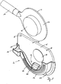
- FIG. 1 shows a holder 2 according to a first embodiment of the present invention.
- a stopping tine 4 is shown before it is inserted into the holder 2.
- the holder 2 comprises a holding plate 6, which has a plurality of recesses 8, into which connection means, for example rivets or screws, can be inserted, by means of which the holding plate 6 can be fastened to a wall, not shown, in an interior of a motor vehicle.
- a receiving tray 10 On the holding plate 6, a receiving tray 10 is provided which has a circular segment-shaped portion 12 and also has a receiving portion 14 for a handle 16 and the handle attachment of the stopping tine 4.
- the receiving tray 10 has recesses 18 in the Connecting means can be introduced, for example, to connect the receiving tray 10 with the holding plate 6 and / or an inner wall of the motor vehicle. In this case, the receiving tray 10 with the holding plate 6 without fasteners, for example by Ultraschall directedung be connected.
- a spring element 20 is arranged in the lower region, which forms the clamping device 22 together with the receiving tray 10.
- the stopping tiller 4 is in FIG. 1 already shown in the position in which it can be introduced from above into the clamping device 22.
- the stopping tiller 4 has a trowel body 24, which is essentially circular.
- a lighting device 26 which may be illuminated, for example, red, so that with the stopping tine 4 vehicles can be stopped or waved out of the flowing traffic.
- the stopping tiller 4 will now be in the in FIG. 1 shown alignment in the holder 2 introduced.
- This situation is in FIG. 2 shown.
- the trowel body is clamped between the spring element 20 and the receiving tray 10.
- the spring element 20 is slightly pushed out of the equilibrium position. As a result, it brings a spring force on the trowel body 24 of the tiller 4, so that it is held in the clamping device 22.
- FIG. 1 It can be seen that in a region of the holding plate 6, a cushion member 28 is arranged. If the stopping tiller 4 is a two-sided stopping tine 4, this points on the in FIG. 1 not shown side of the trowel body 24, a second lighting device 26. So that these are not scratched in the holder 2 or damaged in any other way, the cushioning element 28 is arranged so that the second lighting device 26 comes into contact with the holding plate 6 precisely at this point. Alternatively, too a one-sided stopping tine 4, which has only one side of the trowel body 24 via a lighting device 26, are inserted into the holder. This does not happen as in the FIGS. 1 and 2 shown, but with the lighting device 26 on the other side of the trowel body 24, and the first lighting device 26 is protected by the pad member 28 from scratches and other damage. In FIG. 2 the stopping tiller is in the transport position.
- the stopping tiller is in the transport position.
- FIGS. 3a to 3d show various views of a holder 2 according to an embodiment of the present invention, in which a stopping tine 4 has been introduced. Especially in the Figures 3b, 3c and 3d It can be seen that the stopping turret 4 can definitely also be a two-sided tipping ladle, which has a lighting device 26 on each side of the trowel body 24.
- 3d figure is a sectional view taken along the line AA in FIG. 3a ,
- the spring element 20 can be seen, which together with the receiving tray 10 forms the clamping device 22.
- the trowel body 24 is pressed in from above between the spring element 20 and the receiving tray 10.
- the in 3d figure Upper part of the spring element 20 is pressed to the left, so that the spring element is no longer in the equilibrium position.
- the spring element 20, like all other parts of the holder 2 is advantageously provided with a padding element 28 in order to protect the ladle body 24 and the lighting devices 26 from damage.
- two spring elements could be provided, one of which is arranged on the left and one right of the trowel body. It is also conceivable to provide no additional spring element 20, but the receiving tray 10 in such a way that it forms the clamping device 22 together with the holding plate 6. However, if the holding plate 6 then does not have a recess for a second lighting device 26, In this embodiment, only a one-sided stopping tiller could be inserted into the clamping device 22 and thus into the holder 2.
- FIG. 4 shows all components of a holder 2 according to an embodiment of the present invention in an exploded view.
- One recognizes the holding plate 6 with the recesses 8, the spring element 20 and the receiving tray 10, which has the circular segment-shaped portion 12 and a receiving portion 14 for a handle 16 of the stopping tine 4.
- FIG. 4 clearly visible are three padding elements 28.
- the circular padding element 28 is already in FIG. 1
- the crescent-shaped padding element 28 is arranged on the side facing the holding plate 6 of the circular segment-shaped region 12 of the receiving tray 10.
- the third pad member 28 is applied to the spring member 20 so as to protect the second side of the trowel body 24, which comes into contact with a component of the holder 2, from scratches and other damage.
Landscapes
- Business, Economics & Management (AREA)
- Emergency Management (AREA)
- Physics & Mathematics (AREA)
- General Physics & Mathematics (AREA)
- Clamps And Clips (AREA)
- Fittings On The Vehicle Exterior For Carrying Loads, And Devices For Holding Or Mounting Articles (AREA)
- Automobile Manufacture Line, Endless Track Vehicle, Trailer (AREA)
- Handcart (AREA)
- Soil Working Implements (AREA)
- Absorbent Articles And Supports Therefor (AREA)
- Supporting Of Heads In Record-Carrier Devices (AREA)
Abstract
Description
- Die Erfindung betrifft einen Halter für eine Anhaltekelle.
- Anhaltekellen werden beispielsweise von der Verkehrspolizei benutzt, um einzelne Fahrzeuge aus einem fließenden Fahrzeugstrom herauszuwinken. Dies geschieht üblicherweise während der Fahrt, indem ein auf dem Beifahrersitz sitzender Beamter die Anhaltekelle aus dem geöffneten Beifahrerfenster hält und so dem Fahrer des hinter ihm bzw. schräg neben ihm fahrenden Fahrzeugs bedeutet, ihm zu folgen, anzuhalten oder an der nächsten Möglichkeit beispielsweise eine Autobahn zu verlassen.
- Damit eine derartige Anhaltekelle für die Beamten schnell und einfach greifbar ist, wird sie in der Regel in einem Seitenstaufach in der Beifahrertür oder einer Mittelkonsole verwahrt. Diese Fächer sind nicht speziell für die Aufnahme einer derartigen Anhaltekelle ausgerüstet, sondern sind allgemein als Staufächer für verschiedenste Gegenstände vorgesehen und weisen in der Regel keinen Deckel auf. Die Kelle liegt folglich lediglich lose im Innenraum des Fahrzeugs.
- Dies weist mehrere Nachteile auf. Eine lose in dem Staufach liegende Kelle wird durch die Bewegung des Kraftfahrzeuges beispielsweise bei Kurvenfahrten, durch Bremsen und Beschleunigen oder das Überfahren eines Hindernisses oder eines Schlagloches in dem sie aufnehmenden Behältnis hin und her geschleudert. Dabei kommt es zum einen zu einer nicht unerheblichen Geräuschentwicklung, die auf Dauer die Fahrzeuginsassen stört, und zum anderen zu Beschädigungen der Anhaltekelle in Form von Kratzern oder abgebrochenen Teilstücken. Zudem kann eine lediglich lose in einem Behältnis liegende Kelle im Falle eines Unfalles ungehindert das Behältnis verlassen und durch den Innenraum des Kraftfahrzeugs geschleudert werden. Sie stellt in diesem Fall ein erhebliches Verletzungsrisiko für die sich im Fahrzeug befindenden Personen dar. Dies ist insbesondere bei Unfällen zu befürchten, bei denen sich das Fahrzeug, in dem die Kelle gelagert ist, überschlägt.
- Der Erfindung liegt somit die Aufgabe zugrunde, eine Verstaumöglichkeit für eine Anhaltekelle im Innenraum eines Kraftfahrzeuges vorzuschlagen, in der die Anhaltekelle fest und sicher verstaut und dennoch leicht zugänglich ist.
- Die Erfindung löst die gestellte Aufgabe durch einen Halter für eine Anhaltekeile mit einer im Innenraum eines Kraftfahrzeuges befestigbaren Halteplatte, einer an der Halteplatte angeordneten Aufnahmeschale und einer Klemmvorrichtung zum Einklemmen der Anhaltekelle in einer Transportposition.
- Mit der Halteplatte ist der erfindungsgemäße Halter beispielsweise an der Innenseite der Beifahrertür des Kraftfahrzeuges befestigbar. Dabei wird die Halteplatte beispielsweise über Schrauben, Nieten oder ähnliches an der jeweiligen Position im Innenraum des Kraftfahrzeugs angebracht. Die Halteplatte kann auch geklebt oder in sonstiger Weise befestigt sein. Die Anhaltekelle kann dann in die Klemmvorrichtung eingebracht werden und wird in dieser in der Transportposition gehalten. Dadurch ist die Anhaltekelle fixiert und kann auch bei extremen Fahrmanövern oder Unfällen nicht durch den Innenraum geschleudert werden. Gleichzeitig ist durch das simple Einklemmen die Anhaltekelle einfach und schnell zu verstauen und genau so einfach dem Halter bzw. der Klemmvorrichtung wieder zu entnehmen. Auch ein Umherfliegen während normaler Fahrmanöver wird durch den erfindungsgemäßen Halter sicher verhindert, so dass es nicht zu einem Klappern oder einer Beschädigung der Anhaltekelle während der Fahrt kommen kann.
- In einer bevorzugten Ausführungsform der vorliegenden Erfindung umfasst die Klemmvorrichtung wenigstens ein Federelement, das derart angeordnet ist, dass die Anhaltekelle zwischen dem wenigstens einen Federelement und der Aufnahmeschale einklemmbar ist. Dabei wird während des Einklemmens der Anhaltekelle das Federelement aus der Gleichgewichtslage herausgedrückt und so durch die Federkraft federbeaufschlagt. Die Aufnahmekelle, die zwischen dem wenigstens einen Federelement und der Aufnahmeschale eingeklemmt ist, wird somit durch diese Federkraft in der Transportposition gehalten.
- Unter der Gleichgewichtslage des wenigstens einen Federelementes wird im Folgenden die Lage verstanden, in der sich das wenigstens eine Federelement befindet, wenn sich keine Anhaltekelle im Halter befindet. In dieser Lage kann das Federelement durchaus bereits eine Kraft auf des jeweils andere Bauteil der Klemmvorrichtung, ausüben. Das wenigstens eine Federelement wäre in diesem Fall vorgespannt, so dass die auf die Anhaltekelle ausgeübte Kraft größer ist, als wenn das Federelement nicht vorgespannt wäre. Dadurch wird die Haltekraft vergrößert und somit die Stabilität der Lagerung der Kelle im Halter erhöht.
- Alternativ oder zusätzlich dazu kann die Klemmvorrichtung auch zwei Federelemente umfassen, die derart angeordnet sind, dass die Anhaltekelle zwischen den beiden Federelementen einklemmbar ist. Dabei ist das Wirkprinzip identisch. Beim Einsetzen der Anhaltekelle in der Transportposition in die Klemmvorrichtung werden in dieser Ausgestaltung die beiden Federelemente aus der Gleichgewichtslage bewegt und somit in der entgegen gesetzten Richtung federbelastet. Dadurch entsteht eine Klemmwirkung, die die Anhaltekelle in der Transportposition innerhalb der Klemmvorrichtung festhält.
- Die Federelemente können dabei bevorzugt mit der Halteplatte oder der Aufnahmeschale vernietet sein. Natürlich sind auch andere Möglichkeiten der Befestigung, beispielsweise Kleben oder Schrauben, möglich.
- In einer konstruktiv besonders einfachen Ausgestaltung wird die Klemmvorrichtung durch die Halteplatte und zumindest einen Teil der Aufnahmeschale gebildet. Es ist dann kein separates Federelement nötig, wodurch der Produktionsaufwand und damit die Herstellungskosten reduziert werden. Die Aufnahmeschale ist in diesem Fall so ausgestaltet, dass die Anhaltekelle zwischen der Halteplatte und der Aufnahmeschale eingeklemmt werden kann. Dazu ist vorzugsweise zu mindest ein Teil der Aufnahmeschale federnd ausgestaltet.
- Vorzugsweise sind die Federelemente und zumindest eine Seite der Aufnahmeschale mit einer Polsterung ausgestattet. Besonders vorteilhafterweise ist auch zumindest ein Teil der Halteplatte mit der Polsterung versehen. Natürlich sind hier auch unterschiedliche Polsterungen denkbar. Damit kann gewährleistet werden, dass alle Teile des Halters, die unmittelbar mit der Anhaltekelle in Kontakt kommen, gepolstert sind, so dass es nicht zu Kratzern oder sonstigen Beschädigungen an der Anhaltekelle kommen kann. Dies ist insbesondere von Vorteil für den mittleren Bereich der Anhaltekelle, da hierzu meist ein leuchtender, oftmals roter oder grüner, Bereich vorgesehen ist. Dies ist zusammen mit dem äußeren Rand der Kelle der gegen mechanische Beanspruchung empfindlichste Bereich der Anhaltekelle, so dass hier eine Polsterung besonders vorteilhaft ist. Die Polsterung kann insbesondere aus einem Polypropylen oder einem anderen Schaumstoff bestehen.
- Vorteilhafterweise ist die Klemmvorrichtung zum Einklemmen einer zweiseitigen Anhaltekelle ausgebildet. Anhaltekellen gibt es in einseitiger und zweiseitiger Ausführung. Bei einer einseitigen Anhaltekelle ist nur auf einer Seite, die hier Vorderseite genannt werden soll, ein leuchtender Bereich vorgesehen. Da hier sowohl Leuchtmittel als auch farbige Abdeckkappen vorgesehen sein müssen, steht dieser Bereich in der Regel in axialer Richtung über die Vorderseite des eigentlichen Kellenkörpers hinaus. Bei einer zweiseitigen Anhaltekelle ist auch auf der der Vorderseite gegenüber liegenden Rückseite eine Leuchtvorrichtung vorgesehen. Diese kann beispielsweise eine andere Farbe haben. Als besonders vorteilhaft hat sich herausgestellt, wenn die in den Halter eingesetzte Anhaltekelle in der Transportposition so angeordnet ist, dass der eigentliche Kellenkörper von der Halteplatte beabstandet angeordnet ist. Dann kann zwischen der Halteplatte und dem eigentlichen Kellenkörper der axial hervorstehende Leuchtbereich mit Leuchtkörper und farbiger Abdeckkappe angeordnet werden.
- In einer konstruktiv besonders einfachen Ausgestaltung ist die Aufnahmeschale beispielsweise mittels Ultraschallschweißung an der Halteplatte befestigt. Dabei sind keine weiteren Verbindungsmittel nötig, sondern die beiden Teile, die vorzugsweise aus einem Kunststoff bestehen, werden mittels Ultraschallschweißung aneinander befestigt. Die Verbindung ist einfach und kostengünstig herzustellen und benötigt keine zusätzlichen Bauteile.
- Vorzugsweise weist die Aufnahmeschale einen kreissegmentförmigen Bereich auf. Dieser dient dann zur Aufnahme des eigentlichen Kellenkörpers, der ebenfalls in der Regel kreisförmig ausgebildet ist. Wird die Aufnahmeschale so ausgebildet, dass sie der Form der Kelle folgt, ist eine besonders sichere Halterung und Lagerung der Kelle in der Transportposition gewährleistet. An einer Seite umfasst die Aufnahmeschale vorteilhafterweise einen Aufnahmebereich für einen Griffansatz der Anhaltekelle. Das ist insbesondere der Teil der Anhaltekelle in der der Griff mit dem eigentlichen Kellenkörper verbunden ist beziehungsweise in diesen übergeht. Dadurch kann gewährleistet werden, dass die Kelle im Halter nicht nur eingeklemmt wird, sondern auch am Griffansatz nochmals einrastet. Natürlich ist auch eine normale Lagerung ohne Rastmechanismus denkbar. Damit ist neben einer besonders sicheren und eindeutigen Lagerung und Transportposition zudem gewährleistet, dass Personen, die nach der Anhaltekelle greifen, wenn sie in der Transportposition in der Klemmvorrichtung eingeklemmt ist, sich keine Verletzung zuziehen können. Auch das Verletzungsrisiko durch den Griff der Anhaltekelle für Beine, Knöchel oder Knie der Insassen des Kraftfahrzeugs wird reduziert.
- Mit Hilfe einer Zeichnung wird nachfolgend ein Ausführungsbeispiel der vorliegenden Erfindung näher erläutert. Es zeigt
- Figur 1
- - einen Halter gemäß einem ersten Ausführungsbeispiel der vorliegenden Erfindung mit einer Anhaltekelle, bevor sie in den Halter eingesetzt wird,
- Figur 2
- - einen Halter gemäß einem Ausführungsbeispiel der vorliegenden Erfindung mit darin eingesetzter Anhaltekelle,
- Figuren 3a - 3d
- - die Situation aus
Figur 2 in einer Frontalansicht (Figur 3a ), einer Draufsicht (Figur 3b ), einer Seitenansicht (Figur 3c ) und einer Schnittansicht entlang der Linie A-A ausFigur 3a (Figur 3d ), - Figur 4
- - einen Halter gemäß einem Ausführungsbeispiel der vorliegenden Erfindung in einer Explosionsdarstellung.
-
Figur 1 zeigt einen Halter 2 gemäß einem ersten Ausführungsbeispiel der vorliegenden Erfindung. InFigur 1 darüber ist eine Anhaltekelle 4 dargestellt, bevor sie in den Halter 2 eingesetzt wird. Der Halter 2 umfasst eine Halteplatte 6, die über mehrere Ausnehmungen 8 verfügt, in die Verbindungsmittel, beispielsweise Nieten oder Schrauben, einsetzbar sind, durch die die Halteplatte 6 an einer nicht gezeigten Wand in einem Innenraum eines Kraftfahrzeuges befestigbar ist. - An der Halteplatte 6 ist eine Aufnahmeschale 10 vorgesehen, die über einen kreissegmentförmigen Bereich 12 verfügt und zudem einen Aufnahmebereich 14 für einen Griff 16 beziehungsweise den Griffansatz der Anhaltekelle 4 aufweist. Auch die Aufnahmeschale 10 verfügt über Ausnehmungen 18, in die Verbindungsmittel eingebracht werden können, um beispielsweise die Aufnahmeschale 10 mit der Halteplatte 6 und/oder einer Innenwand des Kraftfahrzeugs zu verbinden. Dabei kann die Aufnahmeschale 10 mit der Halteplatte 6 auch ohne Befestigungselemente, beispielsweise durch Ultraschweißung, verbunden sein.
- An der Halteplatte 6 ist im unteren Bereich ein Federelement 20 angeordnet, das gemeinsam mit der Aufnahmeschale 10 die Klemmvorrichtung 22 bildet. Die Anhaltekelle 4 ist in
Figur 1 bereits in der Position gezeigt, in der sie von oben in die Klemmvorrichtung 22 eingebracht werden kann. Die Anhaltekelle 4 verfügt dabei über einen Kellenkörper 24, der im Wesentlichen kreisförmig ausgebildet ist. Im mittleren Bereich befindet sich eine Leuchtvorrichtung 26, die beispielsweise rot beleuchtet sein kann, damit mit der Anhaltekelle 4 Fahrzeuge angehalten oder aus dem fließenden Verkehr herausgewunken werden können. - Die Anhaltekelle 4 wird nun in der in
Figur 1 gezeigten Ausrichtung nach unten in den Halter 2 eingeführt. Diese Situation ist inFigur 2 gezeigt. Der Kellenkörper wird dabei zwischen dem Federelement 20 und der Aufnahmeschale 10 eingeklemmt. Dabei wird das Federelement 20 etwas aus der Gleichgewichtslage herausgedrückt. Dadurch bringt es eine Federkraft auf den Kellenkörper 24 der Anhaltekelle 4 auf, so dass diese in der Klemmvorrichtung 22 festgehalten wird. - In
Figur 1 ist zu erkennen, dass in einem Bereich der Halteplatte 6 ein Polsterelement 28 angeordnet ist. Handelt es sich bei der Anhaltekelle 4 um eine zweiseitige Anhaltekelle 4, weist diese auf der inFigur 1 nicht gezeigten Seite des Kellenkörpers 24 eine zweite Leuchtvorrichtung 26 auf. Damit diese im Halter 2 nicht zerkratzt oder in sonstiger Weise beschädigt wird, ist das Polsterelement 28 so angeordnet, dass die zweite Leuchtvorrichtung 26 genau an dieser Stelle mit der Halteplatte 6 in Kontakt kommt. Alternativ dazu kann auch eine einseitige Anhaltekelle 4, die nur auf einer Seite des Kellenkörpers 24 über eine Leuchtvorrichtung 26 verfügt, in den Halter eingeführt werden. Geschieht dies nicht wie in denFiguren 1 und2 gezeigt, sondern mit der Leuchtvorrichtung 26 auf der anderen Seite des Kellenkörpers 24, wird auch die erste Leuchtvorrichtung 26 durch das Polsterelement 28 vor Kratzern und sonstigen Beschädigungen geschützt. InFigur 2 befindet sich die Anhaltekelle in der Transportposition. - Die
Figuren 3a bis 3d zeigen verschiedene Ansichten eines Halters 2 gemäß einem Ausführungsbeispiel der vorliegenden Erfindung, in den eine Anhaltekelle 4 eingebracht wurde. Insbesondere in denFiguren 3b, 3c und 3d ist zu erkennen, dass es sich bei der Anhaltekelle 4 durchaus auch um eine zweiseitige Anhaltekelle handeln kann, die auf jeder Seite des Kellenkörpers 24 über eine Leuchtvorrichtung 26 verfügt. -
Figur 3d ist eine Schnittdarstellung entlang der Linie A-A inFigur 3a . In dieser Schnittdarstellung ist das Federelement 20 zu erkennen, das mit der Aufnahmeschale 10 gemeinsam die Klemmvorrichtung 22 bildet. Man erkennt deutlich, dass der Kellenkörper 24 von oben zwischen das Federelement 20 und die Aufnahmeschale 10 eingedrückt wird. Dabei wird der inFigur 3d obere Teil des Federelementes 20 nach links gedrückt, so dass das Federelement sich nicht mehr in der Gleichgewichtslage befindet. Man erkennt zudem, dass auch das Federelement 20 wie alle anderen Teile des Halters 2 vorteilhafterweise mit einem Polsterelement 28 versehen ist, um den Kellenkörper 24 bzw. die Leuchtvorrichtungen 26 vor Beschädigungen zu schützen. Alternativ zu der inFigur 3d gezeigten Ausführungsform könnten auch zwei Federelemente vorgesehen sein, von denen eines links und eines rechts vom Kellenkörper angeordnet ist. Es ist auch denkbar, kein zusätzliches Federelement 20 vorzusehen, sondern die Aufnahmeschale 10 so auszubilden, dass sie mit der Halteplatte 6 gemeinsam die Klemmvorrichtung 22 bildet. Sofern die Halteplatte 6 dann jedoch nicht über eine Ausnehmung für eine zweite Leuchtvorrichtung 26 verfügt, könnte in dieser Ausgestaltung nur eine einseitige Anhaltekelle in die Klemmvorrichtung 22 und damit in den Halter 2 eingeführt werden. -
Figur 4 zeigt alle Bestandteile eines Halters 2 gemäß einem Ausführungsbeispiel der vorliegenden Erfindung in einer Explosionsdarstellung. Man erkennt die Halteplatte 6 mit den Ausnehmungen 8, das Federelement 20 sowie die Aufnahmeschale 10, die über den kreissegmentförmigen Bereich 12 und einen Aufnahmebereich 14 für einen Griff 16 der Anhaltekelle 4 verfügt. InFigur 4 deutlich zu erkennen sind drei Polsterelemente 28. Das kreisförmige Polsterelement 28 ist das bereits inFigur 1 gezeigte Polsterelement 28. Das halbmondförmige Polsterelement 28 wird an die der Halteplatte 6 zugewandte Seite des kreissegmentförmigen Bereichs 12 der Aufnahmeschale 10 angeordnet. Dadurch wird zumindest eine Seite des Kellenkörpers 24 geschützt, wenn die Anhaltekelle 4 in den Halter 2 eingeführt wird. Das dritte Polsterelement 28 wird auf das Federelement 20 aufgebracht, um so auch die zweite Seite des Kellenkörpers 24, die in Kontakt mit einem Bauteil des Halters 2 kommt, vor Kratzern und sonstigen Beschädigungen zu schützen. -
- 2
- Halter
- 4
- Anhaltekelle
- 6
- Halteplatte
- 8
- Ausnehmung
- 10
- Aufnahmeschale
- 12
- kreissegmentförmiger Bereich
- 14
- Aufnahmebereich
- 16
- Griff
- 18
- Ausnehmung
- 20
- Federelement
- 22
- Klemmvorrichtung
- 24
- Kellenkörper
- 26
- Leuchtvorrichtung
- 28
- Polsterelement
Claims (9)
- Halter (2) für eine Anhaltekelle (4) mit einer im Innenraum eines Kraftfahrzeuges befestigbaren Halteplatte (6), einer an der Halteplatte (6) angeordneten Aufnahmeschale (10) und einer Klemmvorrichtung (22) zum Einklemmen der Anhaltekelle (4) in einer Transportposition.
- Halter (2) nach Anspruch 1, dadurch gekennzeichnet, dass die Klemmvorrichtung (22) wenigstens ein Federelement (20) umfasst, das derart angeordnet ist, dass die Anhaltekelle (4) zwischen dem wenigstens einen Federelement (20) und der Aufnahmeschale (10) einklemmbar ist.
- Halter (2) nach Anspruch 1, dadurch gekennzeichnet, dass die Klemmvorrichtung (22) wenigstens zwei Federelemente (20) umfasst, die derart angeordnet sind, dass die Anhaltekelle (4) zwischen den beiden Federelementen (20) einklemmbar ist.
- Halter (2) nach einem der vorstehenden Ansprüche, dadurch gekennzeichnet, dass die Federelemente (20) und zumindest eine Seite der Aufnahmeschale (10) mit einem Polsterelement (28) ausgestattet sind.
- Halter (2) nach Anspruch 4, dadurch gekennzeichnet, dass das wenigstens eine Polsterelement (28) aus Polypropylen besteht.
- Halter (2) nach einem der vorstehenden Ansprüche, dadurch gekennzeichnet, dass die Klemmvorrichtung (22) zum Einklemmen einer zweiseitigen Anhaltekelle (4) ausgebildet ist.
- Halter (2) nach einem der vorstehenden Ansprüche, dadurch gekennzeichnet, dass die Aufnahmeschale (10) mittels Ultraschweißung an der Halteplatte (6) befestigt ist.
- Halter (2) nach einem der vorstehenden Ansprüche, dadurch gekennzeichnet, dass die Aufnahmeschale (10) einen kreissegmentförmigen Bereich (12) aufweist.
- Halter (2) nach einem der vorstehenden Ansprüche, dadurch gekennzeichnet, dass die Aufnahmeschale (10) an einer Seite einen Aufnahmebereich (14) für einen Griffansatz (16) umfasst.
Priority Applications (2)
| Application Number | Priority Date | Filing Date | Title |
|---|---|---|---|
| PL12000936T PL2490191T3 (pl) | 2011-02-17 | 2012-02-14 | Zamocowanie tarczy do zatrzymywania pojazdów |
| SI201230044T SI2490191T1 (sl) | 2011-02-17 | 2012-02-14 | DrĹľalo za zaustavljalni signalni lopar |
Applications Claiming Priority (1)
| Application Number | Priority Date | Filing Date | Title |
|---|---|---|---|
| DE102011011675A DE102011011675B4 (de) | 2011-02-17 | 2011-02-17 | Halter für Anhaltekelle |
Publications (3)
| Publication Number | Publication Date |
|---|---|
| EP2490191A2 true EP2490191A2 (de) | 2012-08-22 |
| EP2490191A3 EP2490191A3 (de) | 2013-03-06 |
| EP2490191B1 EP2490191B1 (de) | 2014-04-02 |
Family
ID=45654994
Family Applications (1)
| Application Number | Title | Priority Date | Filing Date |
|---|---|---|---|
| EP12000936.0A Not-in-force EP2490191B1 (de) | 2011-02-17 | 2012-02-14 | Halter für Anhaltekelle |
Country Status (11)
| Country | Link |
|---|---|
| EP (1) | EP2490191B1 (de) |
| DE (1) | DE102011011675B4 (de) |
| DK (1) | DK2490191T3 (de) |
| ES (1) | ES2474716T3 (de) |
| HR (1) | HRP20140603T1 (de) |
| PL (1) | PL2490191T3 (de) |
| PT (1) | PT2490191E (de) |
| RS (1) | RS53396B (de) |
| RU (1) | RU2532981C2 (de) |
| SI (1) | SI2490191T1 (de) |
| UA (1) | UA102764C2 (de) |
Family Cites Families (6)
| Publication number | Priority date | Publication date | Assignee | Title |
|---|---|---|---|---|
| DE446588C (de) * | 1927-07-06 | Gustav Adolf Nagel | Signalstab mit bei verschiedenen Lagen des Stabs selbsttaetig ein- und ausschaltender Gluehbirne | |
| DE7501790U (de) * | 1975-01-22 | 1976-08-05 | Elektrotechnische Fabrik Wietek & Co Gmbh, 8060 Dachau | Einrichtung zum elektrischen laden von wiederaufladbaren zellen, insbesondere eines signal- oder anhaltestabs |
| RU2117334C1 (ru) * | 1997-09-16 | 1998-08-10 | Закрытое акционерное общество "ТуИРС" | Жезл для регулирования дорожного движения |
| CA2290108A1 (fr) * | 1999-11-01 | 2001-05-01 | Denis Joyal | Support pour balais a neige |
| DE102007048226A1 (de) * | 2006-10-06 | 2008-04-10 | Brunn Gmbh & Co Kg | Vorrichtung zum Anbringen einer Sondersignalanlage auf einem Fahrzeugdach |
| RU85131U1 (ru) * | 2008-11-21 | 2009-07-27 | Открытое акционерное общество "АВТОВАЗ" | Обивка двери легкового автомобиля со вставкой безопасности |
-
2011
- 2011-02-17 DE DE102011011675A patent/DE102011011675B4/de not_active Expired - Fee Related
-
2012
- 2012-02-14 PL PL12000936T patent/PL2490191T3/pl unknown
- 2012-02-14 RS RS20140354A patent/RS53396B/sr unknown
- 2012-02-14 DK DK12000936.0T patent/DK2490191T3/da active
- 2012-02-14 SI SI201230044T patent/SI2490191T1/sl unknown
- 2012-02-14 PT PT120009360T patent/PT2490191E/pt unknown
- 2012-02-14 ES ES12000936.0T patent/ES2474716T3/es active Active
- 2012-02-14 EP EP12000936.0A patent/EP2490191B1/de not_active Not-in-force
- 2012-02-16 UA UAA201201748A patent/UA102764C2/ru unknown
- 2012-02-16 RU RU2012105550/11A patent/RU2532981C2/ru not_active IP Right Cessation
-
2014
- 2014-06-26 HR HRP20140603AT patent/HRP20140603T1/hr unknown
Non-Patent Citations (1)
| Title |
|---|
| None |
Also Published As
| Publication number | Publication date |
|---|---|
| UA102764C2 (ru) | 2013-08-12 |
| RU2012105550A (ru) | 2013-08-27 |
| PT2490191E (pt) | 2014-07-15 |
| RS53396B (sr) | 2014-10-31 |
| DK2490191T3 (da) | 2014-07-07 |
| HRP20140603T1 (hr) | 2014-09-12 |
| DE102011011675B4 (de) | 2013-02-21 |
| EP2490191A3 (de) | 2013-03-06 |
| EP2490191B1 (de) | 2014-04-02 |
| DE102011011675A1 (de) | 2012-08-23 |
| RU2532981C2 (ru) | 2014-11-20 |
| SI2490191T1 (sl) | 2014-09-30 |
| ES2474716T3 (es) | 2014-07-09 |
| PL2490191T3 (pl) | 2014-09-30 |
Similar Documents
| Publication | Publication Date | Title |
|---|---|---|
| WO2014184301A1 (de) | Halteeinrichtung für einen transportablen tonträger | |
| DE102018214456A1 (de) | Ablagefach für einen Innenraum eines Fahrzeugs | |
| DE19754708A1 (de) | Militärfahrzeug zur Personenbeförderung | |
| DE102011053395A1 (de) | Mittelkonsolenanordnung | |
| DE3010817A1 (de) | Kniepolster fuer ein kraftfahrzeug | |
| DE102017210120B4 (de) | Laderaumabdeckung und Kraftfahrzeug | |
| EP2490191B1 (de) | Halter für Anhaltekelle | |
| EP2905176B1 (de) | Lagerungssystem für ausrüstungsgegenstände in einem einsatzfahrzeug | |
| DE4302352A1 (de) | Sicherheitsgurtsystem insbesondere für Kraftfahrzeuge | |
| DE1680020C3 (de) | Mitteltragpfosten für Personenkraftwagen | |
| DE19726192C2 (de) | Kraftfahrzeug mit einer insbesondere im Front- oder Heckbereich angeordneten Batterie | |
| DE3828771C2 (de) | Personenkraftwagen mit einer Anhängevorrichtung | |
| DE102018207259B4 (de) | Befestigungsvorrichtung für eine Transporteinrichtung | |
| DE102010004369B4 (de) | Lösbares Ablagebehältnis für die Aufbewahrung eines Gegenstandes, insbesondere einer Brille oder eines Mobiltelefons in einem Kraftfahrzeug | |
| DE102004010142B4 (de) | Trennwandanordnung für ein Fahrzeug zum Unterteilen des Fahrzeuginnenraumes | |
| DE4229755C2 (de) | Koffer | |
| DE102014204934B3 (de) | Trenneinrichtung zur Abtrennung eines Laderaums von einem Fahrgastraum eines Kraftwagens | |
| DE102014005009A1 (de) | Beidseitig nutzbare Armauflage für ein Kraftfahrzeug und ein Kraftfahrzeug | |
| DE202014007367U1 (de) | Nummerschildträger für Motorräder | |
| DE102013006926B3 (de) | Kraftfahrzeug | |
| DE10134616B4 (de) | Fahrzeugaufbau mit einem Dach und einer an dieses anschließenden Türöffnung | |
| AT5268U1 (de) | Stauvorrichtung für den laderaum eines kraftfahrzeuges | |
| DE102007037763B4 (de) | Vorrichtung zur Unterbringung wenigstens einer Warnweste | |
| DE9305570U1 (de) | Vorrichtung zum Festlegen eines in einem mit Sicherheitsgurten ausgerüsteten Personenkraftwagen mitzuführenden Gegenstandes | |
| DE2804400A1 (de) | Vorrichtung zum festhalten eines unfallopfers |
Legal Events
| Date | Code | Title | Description |
|---|---|---|---|
| PUAI | Public reference made under article 153(3) epc to a published international application that has entered the european phase |
Free format text: ORIGINAL CODE: 0009012 |
|
| AK | Designated contracting states |
Kind code of ref document: A2 Designated state(s): AL AT BE BG CH CY CZ DE DK EE ES FI FR GB GR HR HU IE IS IT LI LT LU LV MC MK MT NL NO PL PT RO RS SE SI SK SM TR |
|
| AX | Request for extension of the european patent |
Extension state: BA ME |
|
| PUAL | Search report despatched |
Free format text: ORIGINAL CODE: 0009013 |
|
| AK | Designated contracting states |
Kind code of ref document: A3 Designated state(s): AL AT BE BG CH CY CZ DE DK EE ES FI FR GB GR HR HU IE IS IT LI LT LU LV MC MK MT NL NO PL PT RO RS SE SI SK SM TR |
|
| AX | Request for extension of the european patent |
Extension state: BA ME |
|
| RIC1 | Information provided on ipc code assigned before grant |
Ipc: G08B 5/00 20060101AFI20130125BHEP |
|
| 17P | Request for examination filed |
Effective date: 20130403 |
|
| GRAP | Despatch of communication of intention to grant a patent |
Free format text: ORIGINAL CODE: EPIDOSNIGR1 |
|
| INTG | Intention to grant announced |
Effective date: 20131004 |
|
| GRAS | Grant fee paid |
Free format text: ORIGINAL CODE: EPIDOSNIGR3 |
|
| GRAA | (expected) grant |
Free format text: ORIGINAL CODE: 0009210 |
|
| AK | Designated contracting states |
Kind code of ref document: B1 Designated state(s): AL AT BE BG CH CY CZ DE DK EE ES FI FR GB GR HR HU IE IS IT LI LT LU LV MC MK MT NL NO PL PT RO RS SE SI SK SM TR |
|
| REG | Reference to a national code |
Ref country code: GB Ref legal event code: FG4D Free format text: NOT ENGLISH |
|
| REG | Reference to a national code |
Ref country code: AT Ref legal event code: REF Ref document number: 660521 Country of ref document: AT Kind code of ref document: T Effective date: 20140415 Ref country code: CH Ref legal event code: EP |
|
| REG | Reference to a national code |
Ref country code: IE Ref legal event code: FG4D Free format text: LANGUAGE OF EP DOCUMENT: GERMAN |
|
| REG | Reference to a national code |
Ref country code: DE Ref legal event code: R096 Ref document number: 502012000522 Country of ref document: DE Effective date: 20140522 |
|
| REG | Reference to a national code |
Ref country code: RO Ref legal event code: EPE |
|
| REG | Reference to a national code |
Ref country code: HR Ref legal event code: TUEP Ref document number: P20140603 Country of ref document: HR |
|
| REG | Reference to a national code |
Ref country code: DK Ref legal event code: T3 Effective date: 20140630 |
|
| REG | Reference to a national code |
Ref country code: ES Ref legal event code: FG2A Ref document number: 2474716 Country of ref document: ES Kind code of ref document: T3 Effective date: 20140709 Ref country code: NL Ref legal event code: T3 |
|
| REG | Reference to a national code |
Ref country code: CH Ref legal event code: NV Representative=s name: BRAUNPAT BRAUN EDER AG, CH Ref country code: PT Ref legal event code: SC4A Free format text: AVAILABILITY OF NATIONAL TRANSLATION Effective date: 20140630 |
|
| REG | Reference to a national code |
Ref country code: SE Ref legal event code: TRGR |
|
| REG | Reference to a national code |
Ref country code: GR Ref legal event code: EP Ref document number: 20140401269 Country of ref document: GR Effective date: 20140718 Ref country code: SK Ref legal event code: T3 Ref document number: E 16613 Country of ref document: SK |
|
| REG | Reference to a national code |
Ref country code: NO Ref legal event code: T2 Effective date: 20140402 |
|
| REG | Reference to a national code |
Ref country code: HR Ref legal event code: T1PR Ref document number: P20140603 Country of ref document: HR |
|
| REG | Reference to a national code |
Ref country code: PL Ref legal event code: T3 |
|
| REG | Reference to a national code |
Ref country code: EE Ref legal event code: FG4A Ref document number: E009590 Country of ref document: EE Effective date: 20140721 |
|
| PG25 | Lapsed in a contracting state [announced via postgrant information from national office to epo] |
Ref country code: CY Free format text: LAPSE BECAUSE OF FAILURE TO SUBMIT A TRANSLATION OF THE DESCRIPTION OR TO PAY THE FEE WITHIN THE PRESCRIBED TIME-LIMIT Effective date: 20140402 |
|
| REG | Reference to a national code |
Ref country code: HU Ref legal event code: AG4A Ref document number: E021247 Country of ref document: HU |
|
| REG | Reference to a national code |
Ref country code: DE Ref legal event code: R097 Ref document number: 502012000522 Country of ref document: DE |
|
| PLBE | No opposition filed within time limit |
Free format text: ORIGINAL CODE: 0009261 |
|
| STAA | Information on the status of an ep patent application or granted ep patent |
Free format text: STATUS: NO OPPOSITION FILED WITHIN TIME LIMIT |
|
| REG | Reference to a national code |
Ref country code: HR Ref legal event code: ODRP Ref document number: P20140603 Country of ref document: HR Payment date: 20150210 Year of fee payment: 4 |
|
| REG | Reference to a national code |
Ref country code: FR Ref legal event code: PLFP Year of fee payment: 4 |
|
| 26N | No opposition filed |
Effective date: 20150106 |
|
| PGFP | Annual fee paid to national office [announced via postgrant information from national office to epo] |
Ref country code: NL Payment date: 20150223 Year of fee payment: 4 |
|
| REG | Reference to a national code |
Ref country code: DE Ref legal event code: R097 Ref document number: 502012000522 Country of ref document: DE Effective date: 20150106 |
|
| PGFP | Annual fee paid to national office [announced via postgrant information from national office to epo] |
Ref country code: MC Payment date: 20150219 Year of fee payment: 4 Ref country code: BG Payment date: 20150223 Year of fee payment: 4 Ref country code: CH Payment date: 20150223 Year of fee payment: 4 Ref country code: SK Payment date: 20150206 Year of fee payment: 4 Ref country code: LU Payment date: 20150219 Year of fee payment: 4 Ref country code: IT Payment date: 20150228 Year of fee payment: 4 Ref country code: LT Payment date: 20150204 Year of fee payment: 4 Ref country code: DK Payment date: 20150223 Year of fee payment: 4 Ref country code: PT Payment date: 20150209 Year of fee payment: 4 Ref country code: HU Payment date: 20150216 Year of fee payment: 4 Ref country code: NO Payment date: 20150219 Year of fee payment: 4 Ref country code: RO Payment date: 20150127 Year of fee payment: 4 Ref country code: EE Payment date: 20150219 Year of fee payment: 4 Ref country code: IE Payment date: 20150217 Year of fee payment: 4 Ref country code: FI Payment date: 20150218 Year of fee payment: 4 Ref country code: CZ Payment date: 20150205 Year of fee payment: 4 Ref country code: ES Payment date: 20150223 Year of fee payment: 4 Ref country code: IS Payment date: 20150220 Year of fee payment: 4 |
|
| PGFP | Annual fee paid to national office [announced via postgrant information from national office to epo] |
Ref country code: LV Payment date: 20150220 Year of fee payment: 4 Ref country code: HR Payment date: 20150210 Year of fee payment: 4 Ref country code: TR Payment date: 20150205 Year of fee payment: 4 Ref country code: GR Payment date: 20150217 Year of fee payment: 4 Ref country code: RS Payment date: 20150205 Year of fee payment: 4 Ref country code: FR Payment date: 20150217 Year of fee payment: 4 Ref country code: SI Payment date: 20150205 Year of fee payment: 4 Ref country code: SE Payment date: 20150223 Year of fee payment: 4 |
|
| PGFP | Annual fee paid to national office [announced via postgrant information from national office to epo] |
Ref country code: BE Payment date: 20150216 Year of fee payment: 4 |
|
| REG | Reference to a national code |
Ref country code: DE Ref legal event code: R082 Ref document number: 502012000522 Country of ref document: DE Representative=s name: GRAMM, LINS & PARTNER PATENT- UND RECHTSANWAEL, DE |
|
| PGFP | Annual fee paid to national office [announced via postgrant information from national office to epo] |
Ref country code: PL Payment date: 20150116 Year of fee payment: 4 |
|
| PG25 | Lapsed in a contracting state [announced via postgrant information from national office to epo] |
Ref country code: BE Free format text: LAPSE BECAUSE OF NON-PAYMENT OF DUE FEES Effective date: 20160229 |
|
| REG | Reference to a national code |
Ref country code: HR Ref legal event code: PBON Ref document number: P20140603 Country of ref document: HR Effective date: 20160214 |
|
| REG | Reference to a national code |
Ref country code: LT Ref legal event code: MM4D Effective date: 20160214 |
|
| REG | Reference to a national code |
Ref country code: EE Ref legal event code: MM4A Ref document number: E009590 Country of ref document: EE Effective date: 20160229 |
|
| REG | Reference to a national code |
Ref country code: NO Ref legal event code: MMEP Ref country code: DK Ref legal event code: EBP Effective date: 20160229 |
|
| PG25 | Lapsed in a contracting state [announced via postgrant information from national office to epo] |
Ref country code: MC Free format text: LAPSE BECAUSE OF NON-PAYMENT OF DUE FEES Effective date: 20160229 Ref country code: LU Free format text: LAPSE BECAUSE OF NON-PAYMENT OF DUE FEES Effective date: 20160214 |
|
| REG | Reference to a national code |
Ref country code: CH Ref legal event code: PL |
|
| REG | Reference to a national code |
Ref country code: SE Ref legal event code: EUG |
|
| GBPC | Gb: european patent ceased through non-payment of renewal fee |
Effective date: 20160214 |
|
| PG25 | Lapsed in a contracting state [announced via postgrant information from national office to epo] |
Ref country code: LI Free format text: LAPSE BECAUSE OF NON-PAYMENT OF DUE FEES Effective date: 20160229 Ref country code: LT Free format text: LAPSE BECAUSE OF NON-PAYMENT OF DUE FEES Effective date: 20160214 Ref country code: NO Free format text: LAPSE BECAUSE OF NON-PAYMENT OF DUE FEES Effective date: 20160229 Ref country code: FI Free format text: LAPSE BECAUSE OF NON-PAYMENT OF DUE FEES Effective date: 20160214 Ref country code: EE Free format text: LAPSE BECAUSE OF NON-PAYMENT OF DUE FEES Effective date: 20160229 Ref country code: CH Free format text: LAPSE BECAUSE OF NON-PAYMENT OF DUE FEES Effective date: 20160229 Ref country code: IS Free format text: LAPSE BECAUSE OF FAILURE TO SUBMIT A TRANSLATION OF THE DESCRIPTION OR TO PAY THE FEE WITHIN THE PRESCRIBED TIME-LIMIT Effective date: 20160831 Ref country code: BG Free format text: LAPSE BECAUSE OF NON-PAYMENT OF DUE FEES Effective date: 20160930 Ref country code: HU Free format text: LAPSE BECAUSE OF NON-PAYMENT OF DUE FEES Effective date: 20160215 |
|
| REG | Reference to a national code |
Ref country code: SK Ref legal event code: MM4A Ref document number: E 16613 Country of ref document: SK Effective date: 20160214 |
|
| REG | Reference to a national code |
Ref country code: NL Ref legal event code: MM Effective date: 20160301 |
|
| REG | Reference to a national code |
Ref country code: FR Ref legal event code: ST Effective date: 20161028 |
|
| PG25 | Lapsed in a contracting state [announced via postgrant information from national office to epo] |
Ref country code: SK Free format text: LAPSE BECAUSE OF NON-PAYMENT OF DUE FEES Effective date: 20160214 Ref country code: SE Free format text: LAPSE BECAUSE OF NON-PAYMENT OF DUE FEES Effective date: 20160215 Ref country code: GR Free format text: LAPSE BECAUSE OF NON-PAYMENT OF DUE FEES Effective date: 20160905 Ref country code: LV Free format text: LAPSE BECAUSE OF NON-PAYMENT OF DUE FEES Effective date: 20160214 Ref country code: HR Free format text: LAPSE BECAUSE OF NON-PAYMENT OF DUE FEES Effective date: 20160214 Ref country code: PT Free format text: LAPSE BECAUSE OF NON-PAYMENT OF DUE FEES Effective date: 20160816 Ref country code: CZ Free format text: LAPSE BECAUSE OF NON-PAYMENT OF DUE FEES Effective date: 20160214 Ref country code: RO Free format text: LAPSE BECAUSE OF NON-PAYMENT OF DUE FEES Effective date: 20160214 Ref country code: RS Free format text: LAPSE BECAUSE OF NON-PAYMENT OF DUE FEES Effective date: 20160817 Ref country code: SI Free format text: LAPSE BECAUSE OF NON-PAYMENT OF DUE FEES Effective date: 20160215 |
|
| REG | Reference to a national code |
Ref country code: SI Ref legal event code: KO00 Effective date: 20161013 Ref country code: IE Ref legal event code: MM4A |
|
| PG25 | Lapsed in a contracting state [announced via postgrant information from national office to epo] |
Ref country code: IT Free format text: LAPSE BECAUSE OF NON-PAYMENT OF DUE FEES Effective date: 20160214 |
|
| PGFP | Annual fee paid to national office [announced via postgrant information from national office to epo] |
Ref country code: MT Payment date: 20150223 Year of fee payment: 4 |
|
| PG25 | Lapsed in a contracting state [announced via postgrant information from national office to epo] |
Ref country code: DK Free format text: LAPSE BECAUSE OF NON-PAYMENT OF DUE FEES Effective date: 20160229 Ref country code: GB Free format text: LAPSE BECAUSE OF NON-PAYMENT OF DUE FEES Effective date: 20160214 Ref country code: IE Free format text: LAPSE BECAUSE OF NON-PAYMENT OF DUE FEES Effective date: 20160214 Ref country code: NL Free format text: LAPSE BECAUSE OF NON-PAYMENT OF DUE FEES Effective date: 20160301 Ref country code: FR Free format text: LAPSE BECAUSE OF NON-PAYMENT OF DUE FEES Effective date: 20160229 |
|
| REG | Reference to a national code |
Ref country code: GR Ref legal event code: ML Ref document number: 20140401269 Country of ref document: GR Effective date: 20160905 |
|
| PG25 | Lapsed in a contracting state [announced via postgrant information from national office to epo] |
Ref country code: SM Free format text: LAPSE BECAUSE OF FAILURE TO SUBMIT A TRANSLATION OF THE DESCRIPTION OR TO PAY THE FEE WITHIN THE PRESCRIBED TIME-LIMIT Effective date: 20140402 Ref country code: ES Free format text: LAPSE BECAUSE OF NON-PAYMENT OF DUE FEES Effective date: 20160215 |
|
| PG25 | Lapsed in a contracting state [announced via postgrant information from national office to epo] |
Ref country code: PL Free format text: LAPSE BECAUSE OF NON-PAYMENT OF DUE FEES Effective date: 20160214 Ref country code: MT Free format text: LAPSE BECAUSE OF NON-PAYMENT OF DUE FEES Effective date: 20160229 |
|
| PG25 | Lapsed in a contracting state [announced via postgrant information from national office to epo] |
Ref country code: MK Free format text: LAPSE BECAUSE OF FAILURE TO SUBMIT A TRANSLATION OF THE DESCRIPTION OR TO PAY THE FEE WITHIN THE PRESCRIBED TIME-LIMIT Effective date: 20140402 |
|
| PG25 | Lapsed in a contracting state [announced via postgrant information from national office to epo] |
Ref country code: MT Free format text: LAPSE BECAUSE OF NON-PAYMENT OF DUE FEES Effective date: 20160214 |
|
| PG25 | Lapsed in a contracting state [announced via postgrant information from national office to epo] |
Ref country code: AL Free format text: LAPSE BECAUSE OF FAILURE TO SUBMIT A TRANSLATION OF THE DESCRIPTION OR TO PAY THE FEE WITHIN THE PRESCRIBED TIME-LIMIT Effective date: 20140402 |
|
| PGFP | Annual fee paid to national office [announced via postgrant information from national office to epo] |
Ref country code: DE Payment date: 20200226 Year of fee payment: 9 Ref country code: AT Payment date: 20200218 Year of fee payment: 9 |
|
| REG | Reference to a national code |
Ref country code: DE Ref legal event code: R119 Ref document number: 502012000522 Country of ref document: DE |
|
| REG | Reference to a national code |
Ref country code: AT Ref legal event code: MM01 Ref document number: 660521 Country of ref document: AT Kind code of ref document: T Effective date: 20210214 |
|
| PG25 | Lapsed in a contracting state [announced via postgrant information from national office to epo] |
Ref country code: AT Free format text: LAPSE BECAUSE OF NON-PAYMENT OF DUE FEES Effective date: 20210214 |
|
| PG25 | Lapsed in a contracting state [announced via postgrant information from national office to epo] |
Ref country code: DE Free format text: LAPSE BECAUSE OF NON-PAYMENT OF DUE FEES Effective date: 20210901 |
|
| PG25 | Lapsed in a contracting state [announced via postgrant information from national office to epo] |
Ref country code: TR Free format text: LAPSE BECAUSE OF NON-PAYMENT OF DUE FEES Effective date: 20160214 |