EP2489842B1 - Exhaust-gas muffler - Google Patents
Exhaust-gas muffler Download PDFInfo
- Publication number
- EP2489842B1 EP2489842B1 EP20120152705 EP12152705A EP2489842B1 EP 2489842 B1 EP2489842 B1 EP 2489842B1 EP 20120152705 EP20120152705 EP 20120152705 EP 12152705 A EP12152705 A EP 12152705A EP 2489842 B1 EP2489842 B1 EP 2489842B1
- Authority
- EP
- European Patent Office
- Prior art keywords
- exhaust
- gas
- gas chamber
- upstream
- chamber
- Prior art date
- Legal status (The legal status is an assumption and is not a legal conclusion. Google has not performed a legal analysis and makes no representation as to the accuracy of the status listed.)
- Active
Links
Images






Classifications
-
- F—MECHANICAL ENGINEERING; LIGHTING; HEATING; WEAPONS; BLASTING
- F01—MACHINES OR ENGINES IN GENERAL; ENGINE PLANTS IN GENERAL; STEAM ENGINES
- F01N—GAS-FLOW SILENCERS OR EXHAUST APPARATUS FOR MACHINES OR ENGINES IN GENERAL; GAS-FLOW SILENCERS OR EXHAUST APPARATUS FOR INTERNAL-COMBUSTION ENGINES
- F01N1/00—Silencing apparatus characterised by method of silencing
- F01N1/16—Silencing apparatus characterised by method of silencing by using movable parts
-
- F—MECHANICAL ENGINEERING; LIGHTING; HEATING; WEAPONS; BLASTING
- F01—MACHINES OR ENGINES IN GENERAL; ENGINE PLANTS IN GENERAL; STEAM ENGINES
- F01N—GAS-FLOW SILENCERS OR EXHAUST APPARATUS FOR MACHINES OR ENGINES IN GENERAL; GAS-FLOW SILENCERS OR EXHAUST APPARATUS FOR INTERNAL-COMBUSTION ENGINES
- F01N1/00—Silencing apparatus characterised by method of silencing
- F01N1/08—Silencing apparatus characterised by method of silencing by reducing exhaust energy by throttling or whirling
- F01N1/089—Silencing apparatus characterised by method of silencing by reducing exhaust energy by throttling or whirling using two or more expansion chambers in series
-
- F—MECHANICAL ENGINEERING; LIGHTING; HEATING; WEAPONS; BLASTING
- F01—MACHINES OR ENGINES IN GENERAL; ENGINE PLANTS IN GENERAL; STEAM ENGINES
- F01N—GAS-FLOW SILENCERS OR EXHAUST APPARATUS FOR MACHINES OR ENGINES IN GENERAL; GAS-FLOW SILENCERS OR EXHAUST APPARATUS FOR INTERNAL-COMBUSTION ENGINES
- F01N1/00—Silencing apparatus characterised by method of silencing
- F01N1/16—Silencing apparatus characterised by method of silencing by using movable parts
- F01N1/161—Silencing apparatus characterised by method of silencing by using movable parts for adjusting resonance or dead chambers or passages to resonance or dead chambers
- F01N1/163—Silencing apparatus characterised by method of silencing by using movable parts for adjusting resonance or dead chambers or passages to resonance or dead chambers by means of valves
-
- F—MECHANICAL ENGINEERING; LIGHTING; HEATING; WEAPONS; BLASTING
- F01—MACHINES OR ENGINES IN GENERAL; ENGINE PLANTS IN GENERAL; STEAM ENGINES
- F01N—GAS-FLOW SILENCERS OR EXHAUST APPARATUS FOR MACHINES OR ENGINES IN GENERAL; GAS-FLOW SILENCERS OR EXHAUST APPARATUS FOR INTERNAL-COMBUSTION ENGINES
- F01N1/00—Silencing apparatus characterised by method of silencing
- F01N1/16—Silencing apparatus characterised by method of silencing by using movable parts
- F01N1/166—Silencing apparatus characterised by method of silencing by using movable parts for changing the flow path through the silencer or for adjusting the dimensions of a chamber or a pipe
-
- F—MECHANICAL ENGINEERING; LIGHTING; HEATING; WEAPONS; BLASTING
- F01—MACHINES OR ENGINES IN GENERAL; ENGINE PLANTS IN GENERAL; STEAM ENGINES
- F01N—GAS-FLOW SILENCERS OR EXHAUST APPARATUS FOR MACHINES OR ENGINES IN GENERAL; GAS-FLOW SILENCERS OR EXHAUST APPARATUS FOR INTERNAL-COMBUSTION ENGINES
- F01N2230/00—Combination of silencers and other devices
- F01N2230/04—Catalytic converters
-
- F—MECHANICAL ENGINEERING; LIGHTING; HEATING; WEAPONS; BLASTING
- F01—MACHINES OR ENGINES IN GENERAL; ENGINE PLANTS IN GENERAL; STEAM ENGINES
- F01N—GAS-FLOW SILENCERS OR EXHAUST APPARATUS FOR MACHINES OR ENGINES IN GENERAL; GAS-FLOW SILENCERS OR EXHAUST APPARATUS FOR INTERNAL-COMBUSTION ENGINES
- F01N2290/00—Movable parts or members in exhaust systems for other than for control purposes
- F01N2290/08—Movable parts or members in exhaust systems for other than for control purposes with oscillating or vibrating movement
- F01N2290/10—Movable parts or members in exhaust systems for other than for control purposes with oscillating or vibrating movement actuated by pressure of exhaust gases, e.g. exhaust pulses
-
- F—MECHANICAL ENGINEERING; LIGHTING; HEATING; WEAPONS; BLASTING
- F01—MACHINES OR ENGINES IN GENERAL; ENGINE PLANTS IN GENERAL; STEAM ENGINES
- F01N—GAS-FLOW SILENCERS OR EXHAUST APPARATUS FOR MACHINES OR ENGINES IN GENERAL; GAS-FLOW SILENCERS OR EXHAUST APPARATUS FOR INTERNAL-COMBUSTION ENGINES
- F01N2490/00—Structure, disposition or shape of gas-chambers
- F01N2490/02—Two or more expansion chambers in series connected by means of tubes
- F01N2490/06—Two or more expansion chambers in series connected by means of tubes the gases flowing longitudinally from inlet to outlet in opposite directions
-
- F—MECHANICAL ENGINEERING; LIGHTING; HEATING; WEAPONS; BLASTING
- F01—MACHINES OR ENGINES IN GENERAL; ENGINE PLANTS IN GENERAL; STEAM ENGINES
- F01N—GAS-FLOW SILENCERS OR EXHAUST APPARATUS FOR MACHINES OR ENGINES IN GENERAL; GAS-FLOW SILENCERS OR EXHAUST APPARATUS FOR INTERNAL-COMBUSTION ENGINES
- F01N2490/00—Structure, disposition or shape of gas-chambers
- F01N2490/08—Two or more expansion chambers in series separated by apertured walls only
-
- F—MECHANICAL ENGINEERING; LIGHTING; HEATING; WEAPONS; BLASTING
- F01—MACHINES OR ENGINES IN GENERAL; ENGINE PLANTS IN GENERAL; STEAM ENGINES
- F01N—GAS-FLOW SILENCERS OR EXHAUST APPARATUS FOR MACHINES OR ENGINES IN GENERAL; GAS-FLOW SILENCERS OR EXHAUST APPARATUS FOR INTERNAL-COMBUSTION ENGINES
- F01N2590/00—Exhaust or silencing apparatus adapted to particular use, e.g. for military applications, airplanes, submarines
- F01N2590/04—Exhaust or silencing apparatus adapted to particular use, e.g. for military applications, airplanes, submarines for motorcycles
Definitions
- the present invention relates to an exhaust-gas muffler including a relief valve provided between an upstream exhaust-gas chamber and a downstream exhaust-gas chamber formed in a casing such that exhaust gas is allowed to sequentially flow therethrough.
- the relief valve is configured to open when the pressure of the upstream exhaust-gas chamber is a predetermined value or higher.
- An exhaust-gas muffler with a relief valve is known from Japanese Patent Application Publication No. 2007-321595 .
- a relief valve is provided between an upstream exhaust-gas chamber and a downstream exhaust-gas chamber among a plurality of exhaust-gas chambers which are formed in a casing and through which exhaust gas flows sequentially.
- the relief valve includes a shutter member placed to face an open end of a gas passage between the upstream exhaust-gas chamber and the downstream exhaust-gas chamber, the open end of the gas passage being open to the downstream exhaust-gas chamber, a spring for biasing the shutter member in such a direction that the gas passage is closed, and a seal member fastened to the shutter member so as to be capable of coming in contact with the whole circumference of the open end of the gas passage to the downstream exhaust-gas chamber.
- the seal member is formed into a ring shape corresponding to an open end of a tube member forming the gas passage to the downstream exhaust-gas chamber, to reduce hammering sound produced by a closing action of the relief valve.
- the shutter member of the relief valve is biased by the spring such that the relief valve cannot open until the attainment of a predetermined engine speed, thus controlling output and exhaust-gas sound.
- the relief valve may undesirably open in a configuration in which the dynamic pressure of exhaust gas acts directly on the shutter member in a portion surrounded by the ring-shaped seal member as in the above-described relief valve disclosed in Japanese Patent Application Publication No. 2007-321595 .
- An object of at least the preferred embodiments of the present invention is to provide an exhaust-gas muffler in which a relief valve can be more accurately opened or closed.
- an exhaust-gas muffler including a relief valve provided between two of a plurality of exhaust-gas chambers formed in a casing such that exhaust gas is allowed to sequentially flow therethrough, the two exhaust-gas chambers being an upstream exhaust-gas chamber on an upstream side and a downstream exhaust-gas chamber on a downstream side in a flow direction of the exhaust gas.
- the relief valve includes a shutter member placed to face an open end of a gas passage interposed between the upstream exhaust-gas chamber and the downstream exhaust-gas chamber, the open end of the gas passage being open to the downstream exhaust-gas chamber; a spring for biasing the shutter member in such a direction that the gas passage is closed; and a seal member fastened to the shutter member so as to be capable of coming in contact with the whole circumference of the open end of the gas passage to the downstream exhaust-gas chamber.
- the relief valve is configured to open when the pressure of the upstream exhaust-gas chamber is a predetermined value or higher.
- the seal member is made of a metal mesh material and is formed into a disc shape to cover an exit of the gas passage.
- the seal member fastened to the shutter member is made of a metal mesh material and formed into a disc shape to cover the exit of the gas passage, the dynamic pressure acts on the shutter member through the seal member even in the rare case where the dynamic pressure of exhaust gas increases instantaneously. Since the exhaust gas is disturbed by the seal member made of the mesh material, the dynamic pressure acting on the shutter member can be lowered. Accordingly, even when the dynamic pressure of the exhaust gas instantaneously increases, the relief valve is difficult to open, and the relief valve can be accurately opened and closed.
- an inside of the casing is partitioned by a plurality of separators forming the plurality of exhaust-gas chambers in the casing, a tube member forming the gas passage is fixed to at least one of the separators, and a ring plate with which an outer circumferential portion of the seal member is to come in contact is fastened to the tube member so as to surround the exit of the gas passage.
- the pair of separators forming the upstream exhaust-gas chamber therebetween are fixed to the casing with a reinforcing plate member which is common to these separators.
- the reinforcing plate member supports a catalytic converter housed in the upstream exhaust-gas chamber and connected to an exhaust pipe for introducing exhaust gas into the upstream exhaust-gas chamber.
- the catalytic converter Since the catalytic converter is supported by the reinforcing plate member, the catalytic converter can be supported by taking advantage of the rigidity of the reinforcing plate member.
- a cover member for covering the open end of the tube member to the upstream exhaust-gas chamber is fixed to the separator which supports the tube member and faces the upstream exhaust-gas chamber.
- the dynamic pressure in the upstream exhaust-gas chamber is not transmitted directly to the shutter member side of the relief valve.
- the relief valve can be more accurately opened and closed.
- the second collective exhaust pipe 27 of the embodiment corresponds to the exhaust pipe of the present invention
- the first exhaust-gas chamber 36 of the embodiment corresponds to the upstream exhaust-gas chamber of the present invention
- the third exhaust-gas chamber 38 of the embodiment corresponds to the downstream exhaust-gas chamber of the present invention.
- FIGS. 1 to 11 An embodiment of the present invention will be described with reference to the accompanying FIGS. 1 to 11 .
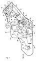
- FIG. 1 shows a motorcycle with a body frame F.
- a front fork 12 pivotally supporting a front wheel WF is movably supported so that steering can be performed.
- the body frame F includes a pivot plate 13 in an intermediate portion in the longitudinal direction thereof.
- the pivot plate 13 supports a front end portion of a swing arm 14 in a vertically swingable manner.
- a rear end portion of the swing arm 14 pivotally supports a rear wheel WR.
- a rear cushion unit 16 is provided between a link mechanism 15, which is provided between the swing arm 14 and the pivot plate 13, and the body frame F.
- An engine main body 17 of an engine E is mounted on the body frame F to be placed between the front wheel WF and the rear wheel WR.
- Chain-type driving means 22 including an endless chain 21 is provided between an output shaft 20 of a transmission (not shown) housed in a crankcase 18 of the engine main body 17 and the rear wheel WR.
- the engine E is a multi-cylinder engine, for example an in-line four-cylinder engine.
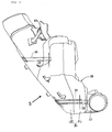
- An exhaust-gas system 25 of the engine E includes individual exhaust pipes 25, one for each cylinder, having upstream ends thereof connected to a front surface of a cylinder head 19 constituting part of the engine main body 17; a pair of first collective exhaust pipes 26, each of which joins two of the individual exhaust pipes 25 together; a second collective exhaust pipe 27, which joins the first collective exhaust pipes 26, together; and an exhaust-gas muffler 28, to which the second collective exhaust pipe 27 is connected.
- the exhaust-gas muffler 28 is placed to the right of the rear wheel WR.
- a casing 30 of the exhaust-gas muffler 28 is formed by joining an inner case member 31 placed at an inner position in the direction of width of the vehicle and an outer case member 32 placed at an outer position in the direction of width of the vehicle together by welding.
- a plurality of cross pipes (in this embodiment, three cross pipes) 33, 34, 35 are provided between the inner case member 31 and the outer case member 32.
- a plurality of exhaust-gas chambers are formed, through which exhaust gas introduced from the second collective exhaust pipe 27 is allowed to sequentially flow.
- there are three exhaust-gas chambers that is, first to third exhaust-gas chambers 36, 37, 38.
- a plurality of separators which in this embodiment are first to third separators 39, 40, 41, are fixed to the casing 30, and partition the inside of the casing 30 to form the first to third exhaust-gas chambers 36, 37, 38.
- the first exhaust-gas chamber 36 is formed in an intermediate portion of the casing 30 in the longitudinal direction thereof.
- the first separator 39 is placed between the second exhaust-gas chamber 37, which is formed in a front portion of the casing 30, and the first exhaust-gas chamber 36.
- the second separator 40 is placed between the third exhaust-gas chamber 38, which is formed in a rear portion of the casing 30, and the first exhaust-gas chamber 36.
- the third separator 41 is fastened to a rear portion of the casing 30, and the third exhaust-gas chamber 38 is formed between the second separator 40 and the third separator 41.
- an end wall member 42 having an opening portion 43 is provided behind the third separator 41 in a rear end portion of the casing 30.
- the first and second separators 39, 40 forming the first exhaust-gas chamber 36 therebetween which is, of the first to third exhaust-gas chambers 36, 37, 38, an exhaust-gas chamber at the most upstream end in the flow direction 65 of exhaust gas, are fixed to the outer case member 32 of the casing 30 with a reinforcing plate member 44, which is common to the separators 39, 40, interposed therebetween.
- a reinforcing plate member 44 In a portion of the reinforcing plate member 44 which is in contact with an inner surface of the outer case member 32, for example, two through holes for welding 45, 46 are provided.
- two through holes for welding 47, 48 corresponding to the through holes for welding 45, 46 are provided as shown in FIG. 4 .
- a first stay 49 is brought into contact with the inner surface of the reinforcing plate member 44. The outer case member 32, the reinforcing plate member 44, and the first stay 49 are welded together using the through holes for welding 45, 47, 46, 48.
- the second collective exhaust pipe 27 passes through a portion of the inner case member 31 of the casing 30, which corresponds to the first exhaust-gas chamber 36.
- a catalytic converter 52 formed by filling a cylindrical case 50 with a catalyst 51 is inserted in and fixed to an open end portion of the second collective exhaust pipe 27.
- a stiffening plate 53 which is brought into contact with and fastened to part of the outer circumference of the open end portion of the second collective exhaust pipe 27, is fastened to the first stay 49 fastened to the reinforcing plate member 44.
- the catalytic converter 52 connected to the second collective exhaust pipe 27 and housed in the first exhaust-gas chamber 36 is supported by the reinforcing plate member 44.
- a second stay 54 which is in contact with the inner surface of the inner case member 31, is fastened to a surface of the outer circumference of the open end portion of the second collective exhaust pipe 27, and specifically to the surface facing the inner case member 31 of the casing 30.
- the second stay 54 is welded to the inner case member 31 using a through hole for welding 55 provided in a portion of the inner case member 31 which corresponds to the second stay 54.
- a first communicating pipe 56 is fastened to the first separator 39 and passes through the first separator 39 such that a communicative connection is established between the first exhaust-gas chamber 36 and the second exhaust-gas chamber 37.
- a second communicating pipe 57 is fastened to the first and second separators 39, 40 and passes through the first and second separators 39, 40 such that a communicative connection is established between the second exhaust-gas chamber 37 and the third exhaust-gas chamber 38.
- a tail pipe 58 is fastened to the third separator 41 and passes through the third separator 41 and the end wall member 42 such that the third exhaust-gas chamber 38 is opened to the outside
- an exhaust-gas control pipe 59 is also fastened to the third separator 41 and passes through the third separator 41 such that one end of the exhaust-gas control pipe 59 is opened to the third exhaust-gas chamber 38.
- the degree of opening of an open portion at the other end of the exhaust-gas control pipe 59 is controlled by an exhaust-gas control valve 61 fastened to a valve stem 60 rotatably supported by the outer case member 32 of the casing 30.
- a guide tube 63 which allows a cable (not shown) connected to a lever 62 fastened to the valve stem 60 to be inserted therethrough is fastened to an upper portion of the casing 30.
- a relief valve 66 is installed between, of the first to third exhaust-gas chambers 36, 37, 38 formed in the casing 30, the exhaust-gas chamber on the upstream side and the exhaust-gas chamber on the downstream side in the flow direction 65 of exhaust gas.
- the relief valve 66 is installed between the first exhaust-gas chamber 36 (which is at the most upstream end in the flow direction 65) and the third exhaust-gas chamber 38 (which is at the most downstream end in the flow direction 65).
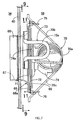
- This relief valve 66 includes a cylindrical tube member 68 fixed to the second separator 40, such that a gas passage 67 is formed between the first and third exhaust-gas chambers 36, 38; a shutter member 69 placed to face an exit of the gas passage 67 to the third exhaust-gas chamber 38; a spring 70 provided between the tube member 68 and the shutter member 69 to bias the shutter member 69 in such a direction that the gas passage 67 is closed; a ring plate 71 fixed to an end portion of the tube member 68 on the third exhaust-gas chamber 38 side so as to surround the exit of the gas passage 67; and a seal member 72 fastened to the shutter member 69 so that an outer circumferential portion of the seal member 72 can come in contact with the ring plate 71.
- the tube member 68 passes through the second separator 40 with one end of the tube member 68 opened to the first exhaust-gas chamber 36.
- the other end of this tube member 68 which is open to the third exhaust-gas chamber 38, has a flange portion 68a provided integrally therewith.
- the flange portion 68a extends outward in the radial direction.
- the shutter member 69 is formed into the shape of an approximately circular disc to face the flange portion 68a at the other end of the tube member 68.
- a pair of guide members 73, 73 are fastened to the outer circumference of the flange portion 68a at the other end of the tube member 68 so that the guide members 73, 73 are located on a diametrical line of the tube member 68.
- Each of the guide members 73, 73 is made by forming a metal rod into an approximately U shape by bending, such that each guide member 73 has a closed end portion 73a at the opposite side from the second separator 40.
- a spring case 74 is fastened to the opposite surface of the shutter member 69 from the tube member 68.
- This spring case 74 has a pair of protruding portions 74a, 74a provided integrally therewith.
- the protruding portions 74a, 74a are inserted into the guide members 73 to guide opening and closing actions of the shutter member 69, and come in contact with the closed end portions 73a of the guide members 73 to restrict the opening of movement of the shutter member 69.
- the spring 70 has a coil portion 70a held by the spring case 74, and a pair of extending arm portions 70b, 70c extending from two ends of the coil portion 70a.
- the outer circumference of the flange portion 68a at the other end of the tube member 68 has engaging protrusions 75, 76 provided integrally therewith.
- the engaging protrusions 75, 76 allow tip portions of the two extending arm portions 70b, 70c to be inserted therethrough and engaged therewith.
- the spring 70 is biased in such a direction that the shutter member 69 is pressed toward the flange portion 68a at the other end of the tube member 68, that is, in such a direction that the gas passage 67 in the tube member 68 is closed.
- the ring plate 71 is formed to have an outer circumference larger than the outer circumference of the shutter member 69, and is fixed to the flange portion 68a at the other end of the tube member 68 to surround the exit of the gas passage 67.
- the seal member 72 is made of a metal mesh material, formed into a disc shape to cover the exit of the gas passage 67 in the tube member 68, and is fastened to a surface of the shutter member 69 which faces the tube member 68.
- the second separator 40 supports the tube member 68 and faces the first exhaust-gas chamber 36.
- a cover member 77 is fixed to the second separator 40 so as to cover the end of the tube member 68 which is open to the first exhaust-gas chamber 36.
- the cover member 77 is formed into a bowl shape, and the cover member 77 on the inner case member 31 side is open to allow exhaust gas to flow from the first exhaust-gas chamber 36 to the gas passage 67.
- the seal member 72 of the relief valve 66 installed between the first and third exhaust-gas chambers 36, 38 is made of a metal mesh material, and formed into a disc shape to cover the exit of the gas passage 67 in the tube member 68 fastened to the second separator 40 between the first and third exhaust-gas chambers 36, 38, the dynamic pressure acts on the shutter member 69 through the seal member 72 even in the rare case where the dynamic pressure of exhaust gas in the first exhaust-gas chamber 36 instantaneously increases.
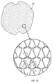
- the exhaust gas passes through a mesh portion of the seal member 72, the exhaust gas collides with the mesh portion, and the flow of the exhaust gas is disturbed as indicated by arrows of FIG. 10 .
- the dynamic pressure acting on the shutter member 69 can be lowered. Accordingly, even when the dynamic pressure of exhaust gas instantaneously increases, the relief valve 66 is difficult to open, and the relief valve 66 can be accurately opened and closed.
- first and second separators 39, 40 forming the first exhaust-gas chamber 36 therebetween are fixed to the casing 30 with the reinforcing plate member 44, which is common to these separators 39, 40, interposed therebetween. Accordingly, the rigidity of the first and second separators 39, 40 is increased, a change in the capacity of the first exhaust-gas chamber 36 associated with a change in the dynamic pressure of exhaust gas is reduced, a change in the pressure of the first exhaust-gas chamber 36 is reduced, and vibrations of the casing 30 are reduced. Thus, the occurrence of noise can be reduced.
- the catalytic converter 52 connected to the second collective exhaust pipe 27 for introducing exhaust gas into the first exhaust-gas chamber 36 and housed in the first exhaust-gas chamber 36 is supported by the reinforcing plate member 44, the catalytic converter 52 can be supported taking advantage of the rigidity of the reinforcing plate member 44.
- the cover member 77 for covering the end of the tube member 68 which is open to the first exhaust-gas chamber 36 is fixed to the second separator 40 supporting the tube member 68 and facing the first exhaust-gas chamber 36. Accordingly, the dynamic pressure in the first exhaust-gas chamber 36 is not transmitted directly to the shutter member 69 side of the relief valve 66. Thus, the relief valve 66 can be more accurately opened and closed.
Landscapes
- Engineering & Computer Science (AREA)
- Chemical & Material Sciences (AREA)
- Combustion & Propulsion (AREA)
- Mechanical Engineering (AREA)
- General Engineering & Computer Science (AREA)
- Exhaust Silencers (AREA)
Applications Claiming Priority (1)
| Application Number | Priority Date | Filing Date | Title |
|---|---|---|---|
| JP2011031579A JP5484374B2 (ja) | 2011-02-17 | 2011-02-17 | 排気マフラー |
Publications (2)
| Publication Number | Publication Date |
|---|---|
| EP2489842A1 EP2489842A1 (en) | 2012-08-22 |
| EP2489842B1 true EP2489842B1 (en) | 2013-03-20 |
Family
ID=45540813
Family Applications (1)
| Application Number | Title | Priority Date | Filing Date |
|---|---|---|---|
| EP20120152705 Active EP2489842B1 (en) | 2011-02-17 | 2012-01-26 | Exhaust-gas muffler |
Country Status (3)
| Country | Link |
|---|---|
| US (1) | US9062581B2 (https=) |
| EP (1) | EP2489842B1 (https=) |
| JP (1) | JP5484374B2 (https=) |
Families Citing this family (5)
| Publication number | Priority date | Publication date | Assignee | Title |
|---|---|---|---|---|
| JP6168853B2 (ja) * | 2013-05-31 | 2017-07-26 | 本田技研工業株式会社 | 自動二輪車用排気装置 |
| JP5889268B2 (ja) * | 2013-12-04 | 2016-03-22 | 本田技研工業株式会社 | 自動二輪車用排気装置 |
| JP6263799B2 (ja) * | 2014-09-30 | 2018-01-24 | 本田技研工業株式会社 | 車両用内燃機関における排気系構造 |
| DE102015224453A1 (de) * | 2015-12-07 | 2017-06-08 | Eberspächer Exhaust Technology GmbH & Co. KG | Schalldämpfer und Herstellungsverfahren |
| DE102022117886B4 (de) * | 2022-07-18 | 2025-12-18 | Bayerische Motoren Werke Aktiengesellschaft | Kraftrad, insbesondere Motorrad |
Family Cites Families (10)
| Publication number | Priority date | Publication date | Assignee | Title |
|---|---|---|---|---|
| JP3379254B2 (ja) * | 1994-12-26 | 2003-02-24 | 日産自動車株式会社 | 排気消音装置 |
| JP3326743B2 (ja) * | 2000-01-21 | 2002-09-24 | 本田技研工業株式会社 | 排気流路制御弁 |
| DE10034557A1 (de) * | 2000-07-15 | 2002-01-24 | Eberspaecher J Gmbh & Co | Ventil in einer abgas-Schalldämpfer-Anlage eines Kraftfahrzeugs |
| JP2002089257A (ja) * | 2000-09-11 | 2002-03-27 | Calsonic Kansei Corp | 制御マフラ用バルブおよび制御マフラ用バルブの弁体組み付け方法 |
| US6736160B2 (en) * | 2001-02-07 | 2004-05-18 | Calsonic Kansei Corporation | Valve structure for engine exhaust system |
| US6622482B2 (en) * | 2001-06-27 | 2003-09-23 | Environmental Control Corporation | Combined catalytic muffler |
| JP4575172B2 (ja) * | 2005-01-04 | 2010-11-04 | 中央発條株式会社 | 排気流路制御弁 |
| JP4726702B2 (ja) * | 2006-05-30 | 2011-07-20 | 本田技研工業株式会社 | 自動二輪車 |
| DE602006008646D1 (de) * | 2006-12-29 | 2009-10-01 | Magneti Marelli Spa | Schalldämpfer mit variabler Geometrie für ein Abgassystem eines Verbrennungsmotors |
| JP4919864B2 (ja) * | 2007-03-30 | 2012-04-18 | 本田技研工業株式会社 | 鞍乗り型車両用排気装置 |
-
2011
- 2011-02-17 JP JP2011031579A patent/JP5484374B2/ja not_active Expired - Fee Related
-
2012
- 2012-01-26 EP EP20120152705 patent/EP2489842B1/en active Active
- 2012-02-02 US US13/364,319 patent/US9062581B2/en not_active Expired - Fee Related
Also Published As
| Publication number | Publication date |
|---|---|
| JP5484374B2 (ja) | 2014-05-07 |
| JP2012167656A (ja) | 2012-09-06 |
| US20120210701A1 (en) | 2012-08-23 |
| US9062581B2 (en) | 2015-06-23 |
| EP2489842A1 (en) | 2012-08-22 |
Similar Documents
| Publication | Publication Date | Title |
|---|---|---|
| EP2489842B1 (en) | Exhaust-gas muffler | |
| JP5909425B2 (ja) | エンジンの排気装置 | |
| US7451854B2 (en) | Exhaust flow rate control valve | |
| WO2017159020A1 (ja) | 内燃機関の排気装置 | |
| JP2008101622A (ja) | 排気ガスリアマフラー | |
| JP4866440B2 (ja) | 消音器 | |
| US10907525B2 (en) | Vehicle exhaust device | |
| JP2011196242A (ja) | 自動二輪車の排気チャンバ | |
| JP6557372B1 (ja) | 消音器ユニット | |
| JP2014234735A (ja) | 自動二輪車 | |
| JP7155860B2 (ja) | 鞍乗型車両の消音器構造 | |
| JP6404701B2 (ja) | 鞍乗型車両用の消音装置 | |
| EP1929135B1 (en) | Muffler assembly and method for assembling a muffler | |
| JP2016023574A (ja) | 鞍乗型車両用排気管 | |
| JP2006152962A (ja) | エンジンの空燃比制御装置 | |
| JP4680971B2 (ja) | 車両用エンジンの排気制御装置 | |
| JP2006291929A (ja) | 排気ガス浄化機能を有するエンジン | |
| JP2007205348A (ja) | マフラー及びマフラーを備えた車両 | |
| JP6335835B2 (ja) | 排気装置 | |
| JP4073859B2 (ja) | 消音器 | |
| JP6130262B2 (ja) | 自動二輪車の排気装置 | |
| JP2010024934A (ja) | エンジンの排気装置及びそれを備えた車両 | |
| JP4638375B2 (ja) | 排気制御弁 | |
| JP4252869B2 (ja) | エンジンの排気装置 | |
| JP2022030976A (ja) | バルブ内蔵型消音器 |
Legal Events
| Date | Code | Title | Description |
|---|---|---|---|
| PUAI | Public reference made under article 153(3) epc to a published international application that has entered the european phase |
Free format text: ORIGINAL CODE: 0009012 |
|
| AK | Designated contracting states |
Kind code of ref document: A1 Designated state(s): AL AT BE BG CH CY CZ DE DK EE ES FI FR GB GR HR HU IE IS IT LI LT LU LV MC MK MT NL NO PL PT RO RS SE SI SK SM TR |
|
| AX | Request for extension of the european patent |
Extension state: BA ME |
|
| 17P | Request for examination filed |
Effective date: 20120802 |
|
| RIC1 | Information provided on ipc code assigned before grant |
Ipc: F01N 1/16 20060101AFI20120903BHEP Ipc: F01N 1/08 20060101ALI20120903BHEP |
|
| GRAP | Despatch of communication of intention to grant a patent |
Free format text: ORIGINAL CODE: EPIDOSNIGR1 |
|
| GRAS | Grant fee paid |
Free format text: ORIGINAL CODE: EPIDOSNIGR3 |
|
| GRAA | (expected) grant |
Free format text: ORIGINAL CODE: 0009210 |
|
| AK | Designated contracting states |
Kind code of ref document: B1 Designated state(s): AL AT BE BG CH CY CZ DE DK EE ES FI FR GB GR HR HU IE IS IT LI LT LU LV MC MK MT NL NO PL PT RO RS SE SI SK SM TR |
|
| REG | Reference to a national code |
Ref country code: GB Ref legal event code: FG4D |
|
| REG | Reference to a national code |
Ref country code: CH Ref legal event code: EP |
|
| REG | Reference to a national code |
Ref country code: IE Ref legal event code: FG4D |
|
| REG | Reference to a national code |
Ref country code: AT Ref legal event code: REF Ref document number: 602222 Country of ref document: AT Kind code of ref document: T Effective date: 20130415 |
|
| REG | Reference to a national code |
Ref country code: DE Ref legal event code: R096 Ref document number: 602012000019 Country of ref document: DE Effective date: 20130516 |
|
| PG25 | Lapsed in a contracting state [announced via postgrant information from national office to epo] |
Ref country code: BG Free format text: LAPSE BECAUSE OF FAILURE TO SUBMIT A TRANSLATION OF THE DESCRIPTION OR TO PAY THE FEE WITHIN THE PRESCRIBED TIME-LIMIT Effective date: 20130620 Ref country code: ES Free format text: LAPSE BECAUSE OF FAILURE TO SUBMIT A TRANSLATION OF THE DESCRIPTION OR TO PAY THE FEE WITHIN THE PRESCRIBED TIME-LIMIT Effective date: 20130701 Ref country code: SE Free format text: LAPSE BECAUSE OF FAILURE TO SUBMIT A TRANSLATION OF THE DESCRIPTION OR TO PAY THE FEE WITHIN THE PRESCRIBED TIME-LIMIT Effective date: 20130320 Ref country code: NO Free format text: LAPSE BECAUSE OF FAILURE TO SUBMIT A TRANSLATION OF THE DESCRIPTION OR TO PAY THE FEE WITHIN THE PRESCRIBED TIME-LIMIT Effective date: 20130620 Ref country code: LT Free format text: LAPSE BECAUSE OF FAILURE TO SUBMIT A TRANSLATION OF THE DESCRIPTION OR TO PAY THE FEE WITHIN THE PRESCRIBED TIME-LIMIT Effective date: 20130320 |
|
| REG | Reference to a national code |
Ref country code: AT Ref legal event code: MK05 Ref document number: 602222 Country of ref document: AT Kind code of ref document: T Effective date: 20130320 |
|
| REG | Reference to a national code |
Ref country code: LT Ref legal event code: MG4D |
|
| PG25 | Lapsed in a contracting state [announced via postgrant information from national office to epo] |
Ref country code: GR Free format text: LAPSE BECAUSE OF FAILURE TO SUBMIT A TRANSLATION OF THE DESCRIPTION OR TO PAY THE FEE WITHIN THE PRESCRIBED TIME-LIMIT Effective date: 20130621 Ref country code: LV Free format text: LAPSE BECAUSE OF FAILURE TO SUBMIT A TRANSLATION OF THE DESCRIPTION OR TO PAY THE FEE WITHIN THE PRESCRIBED TIME-LIMIT Effective date: 20130320 Ref country code: FI Free format text: LAPSE BECAUSE OF FAILURE TO SUBMIT A TRANSLATION OF THE DESCRIPTION OR TO PAY THE FEE WITHIN THE PRESCRIBED TIME-LIMIT Effective date: 20130320 Ref country code: SI Free format text: LAPSE BECAUSE OF FAILURE TO SUBMIT A TRANSLATION OF THE DESCRIPTION OR TO PAY THE FEE WITHIN THE PRESCRIBED TIME-LIMIT Effective date: 20130320 |
|
| REG | Reference to a national code |
Ref country code: NL Ref legal event code: VDEP Effective date: 20130320 |
|
| PG25 | Lapsed in a contracting state [announced via postgrant information from national office to epo] |
Ref country code: HR Free format text: LAPSE BECAUSE OF FAILURE TO SUBMIT A TRANSLATION OF THE DESCRIPTION OR TO PAY THE FEE WITHIN THE PRESCRIBED TIME-LIMIT Effective date: 20130320 Ref country code: BE Free format text: LAPSE BECAUSE OF FAILURE TO SUBMIT A TRANSLATION OF THE DESCRIPTION OR TO PAY THE FEE WITHIN THE PRESCRIBED TIME-LIMIT Effective date: 20130320 Ref country code: RS Free format text: LAPSE BECAUSE OF FAILURE TO SUBMIT A TRANSLATION OF THE DESCRIPTION OR TO PAY THE FEE WITHIN THE PRESCRIBED TIME-LIMIT Effective date: 20130320 |
|
| PG25 | Lapsed in a contracting state [announced via postgrant information from national office to epo] |
Ref country code: PT Free format text: LAPSE BECAUSE OF FAILURE TO SUBMIT A TRANSLATION OF THE DESCRIPTION OR TO PAY THE FEE WITHIN THE PRESCRIBED TIME-LIMIT Effective date: 20130722 Ref country code: RO Free format text: LAPSE BECAUSE OF FAILURE TO SUBMIT A TRANSLATION OF THE DESCRIPTION OR TO PAY THE FEE WITHIN THE PRESCRIBED TIME-LIMIT Effective date: 20130320 Ref country code: EE Free format text: LAPSE BECAUSE OF FAILURE TO SUBMIT A TRANSLATION OF THE DESCRIPTION OR TO PAY THE FEE WITHIN THE PRESCRIBED TIME-LIMIT Effective date: 20130320 Ref country code: NL Free format text: LAPSE BECAUSE OF FAILURE TO SUBMIT A TRANSLATION OF THE DESCRIPTION OR TO PAY THE FEE WITHIN THE PRESCRIBED TIME-LIMIT Effective date: 20130320 Ref country code: AT Free format text: LAPSE BECAUSE OF FAILURE TO SUBMIT A TRANSLATION OF THE DESCRIPTION OR TO PAY THE FEE WITHIN THE PRESCRIBED TIME-LIMIT Effective date: 20130320 Ref country code: IS Free format text: LAPSE BECAUSE OF FAILURE TO SUBMIT A TRANSLATION OF THE DESCRIPTION OR TO PAY THE FEE WITHIN THE PRESCRIBED TIME-LIMIT Effective date: 20130720 Ref country code: SK Free format text: LAPSE BECAUSE OF FAILURE TO SUBMIT A TRANSLATION OF THE DESCRIPTION OR TO PAY THE FEE WITHIN THE PRESCRIBED TIME-LIMIT Effective date: 20130320 Ref country code: CZ Free format text: LAPSE BECAUSE OF FAILURE TO SUBMIT A TRANSLATION OF THE DESCRIPTION OR TO PAY THE FEE WITHIN THE PRESCRIBED TIME-LIMIT Effective date: 20130320 |
|
| PG25 | Lapsed in a contracting state [announced via postgrant information from national office to epo] |
Ref country code: CY Free format text: LAPSE BECAUSE OF FAILURE TO SUBMIT A TRANSLATION OF THE DESCRIPTION OR TO PAY THE FEE WITHIN THE PRESCRIBED TIME-LIMIT Effective date: 20130320 Ref country code: PL Free format text: LAPSE BECAUSE OF FAILURE TO SUBMIT A TRANSLATION OF THE DESCRIPTION OR TO PAY THE FEE WITHIN THE PRESCRIBED TIME-LIMIT Effective date: 20130320 |
|
| PLBE | No opposition filed within time limit |
Free format text: ORIGINAL CODE: 0009261 |
|
| STAA | Information on the status of an ep patent application or granted ep patent |
Free format text: STATUS: NO OPPOSITION FILED WITHIN TIME LIMIT |
|
| PG25 | Lapsed in a contracting state [announced via postgrant information from national office to epo] |
Ref country code: DK Free format text: LAPSE BECAUSE OF FAILURE TO SUBMIT A TRANSLATION OF THE DESCRIPTION OR TO PAY THE FEE WITHIN THE PRESCRIBED TIME-LIMIT Effective date: 20130320 |
|
| 26N | No opposition filed |
Effective date: 20140102 |
|
| REG | Reference to a national code |
Ref country code: DE Ref legal event code: R097 Ref document number: 602012000019 Country of ref document: DE Effective date: 20140102 |
|
| PG25 | Lapsed in a contracting state [announced via postgrant information from national office to epo] |
Ref country code: LU Free format text: LAPSE BECAUSE OF FAILURE TO SUBMIT A TRANSLATION OF THE DESCRIPTION OR TO PAY THE FEE WITHIN THE PRESCRIBED TIME-LIMIT Effective date: 20140126 |
|
| REG | Reference to a national code |
Ref country code: FR Ref legal event code: ST Effective date: 20140930 |
|
| REG | Reference to a national code |
Ref country code: IE Ref legal event code: MM4A |
|
| REG | Reference to a national code |
Ref country code: DE Ref legal event code: R084 Ref document number: 602012000019 Country of ref document: DE |
|
| PG25 | Lapsed in a contracting state [announced via postgrant information from national office to epo] |
Ref country code: FR Free format text: LAPSE BECAUSE OF NON-PAYMENT OF DUE FEES Effective date: 20140131 |
|
| REG | Reference to a national code |
Ref country code: DE Ref legal event code: R084 Ref document number: 602012000019 Country of ref document: DE Effective date: 20141120 |
|
| PG25 | Lapsed in a contracting state [announced via postgrant information from national office to epo] |
Ref country code: IE Free format text: LAPSE BECAUSE OF NON-PAYMENT OF DUE FEES Effective date: 20140126 |
|
| PG25 | Lapsed in a contracting state [announced via postgrant information from national office to epo] |
Ref country code: MC Free format text: LAPSE BECAUSE OF FAILURE TO SUBMIT A TRANSLATION OF THE DESCRIPTION OR TO PAY THE FEE WITHIN THE PRESCRIBED TIME-LIMIT Effective date: 20130320 |
|
| REG | Reference to a national code |
Ref country code: CH Ref legal event code: PL |
|
| PG25 | Lapsed in a contracting state [announced via postgrant information from national office to epo] |
Ref country code: CH Free format text: LAPSE BECAUSE OF NON-PAYMENT OF DUE FEES Effective date: 20150131 Ref country code: LI Free format text: LAPSE BECAUSE OF NON-PAYMENT OF DUE FEES Effective date: 20150131 |
|
| PG25 | Lapsed in a contracting state [announced via postgrant information from national office to epo] |
Ref country code: MT Free format text: LAPSE BECAUSE OF FAILURE TO SUBMIT A TRANSLATION OF THE DESCRIPTION OR TO PAY THE FEE WITHIN THE PRESCRIBED TIME-LIMIT Effective date: 20130320 |
|
| PG25 | Lapsed in a contracting state [announced via postgrant information from national office to epo] |
Ref country code: SM Free format text: LAPSE BECAUSE OF FAILURE TO SUBMIT A TRANSLATION OF THE DESCRIPTION OR TO PAY THE FEE WITHIN THE PRESCRIBED TIME-LIMIT Effective date: 20130320 |
|
| PG25 | Lapsed in a contracting state [announced via postgrant information from national office to epo] |
Ref country code: TR Free format text: LAPSE BECAUSE OF FAILURE TO SUBMIT A TRANSLATION OF THE DESCRIPTION OR TO PAY THE FEE WITHIN THE PRESCRIBED TIME-LIMIT Effective date: 20130320 Ref country code: HU Free format text: LAPSE BECAUSE OF FAILURE TO SUBMIT A TRANSLATION OF THE DESCRIPTION OR TO PAY THE FEE WITHIN THE PRESCRIBED TIME-LIMIT; INVALID AB INITIO Effective date: 20120126 |
|
| PG25 | Lapsed in a contracting state [announced via postgrant information from national office to epo] |
Ref country code: MK Free format text: LAPSE BECAUSE OF FAILURE TO SUBMIT A TRANSLATION OF THE DESCRIPTION OR TO PAY THE FEE WITHIN THE PRESCRIBED TIME-LIMIT Effective date: 20130320 |
|
| PG25 | Lapsed in a contracting state [announced via postgrant information from national office to epo] |
Ref country code: AL Free format text: LAPSE BECAUSE OF FAILURE TO SUBMIT A TRANSLATION OF THE DESCRIPTION OR TO PAY THE FEE WITHIN THE PRESCRIBED TIME-LIMIT Effective date: 20130320 |
|
| PGFP | Annual fee paid to national office [announced via postgrant information from national office to epo] |
Ref country code: IT Payment date: 20190221 Year of fee payment: 9 |
|
| GBPC | Gb: european patent ceased through non-payment of renewal fee |
Effective date: 20200126 |
|
| PG25 | Lapsed in a contracting state [announced via postgrant information from national office to epo] |
Ref country code: GB Free format text: LAPSE BECAUSE OF NON-PAYMENT OF DUE FEES Effective date: 20200126 |
|
| PG25 | Lapsed in a contracting state [announced via postgrant information from national office to epo] |
Ref country code: IT Free format text: LAPSE BECAUSE OF NON-PAYMENT OF DUE FEES Effective date: 20200126 |
|
| REG | Reference to a national code |
Ref country code: DE Ref legal event code: R082 Ref document number: 602012000019 Country of ref document: DE |
|
| PGFP | Annual fee paid to national office [announced via postgrant information from national office to epo] |
Ref country code: DE Payment date: 20251217 Year of fee payment: 15 |