EP2487451B1 - Hohlladungspenetrator - Google Patents
Hohlladungspenetrator Download PDFInfo
- Publication number
- EP2487451B1 EP2487451B1 EP12000643.2A EP12000643A EP2487451B1 EP 2487451 B1 EP2487451 B1 EP 2487451B1 EP 12000643 A EP12000643 A EP 12000643A EP 2487451 B1 EP2487451 B1 EP 2487451B1
- Authority
- EP
- European Patent Office
- Prior art keywords
- penetrator
- charge
- opening
- hollow
- tip
- Prior art date
- Legal status (The legal status is an assumption and is not a legal conclusion. Google has not performed a legal analysis and makes no representation as to the accuracy of the status listed.)
- Active
Links
Images

Classifications
-
- F—MECHANICAL ENGINEERING; LIGHTING; HEATING; WEAPONS; BLASTING
- F42—AMMUNITION; BLASTING
- F42B—EXPLOSIVE CHARGES, e.g. FOR BLASTING, FIREWORKS, AMMUNITION
- F42B12/00—Projectiles, missiles or mines characterised by the warhead, the intended effect, or the material
- F42B12/02—Projectiles, missiles or mines characterised by the warhead, the intended effect, or the material characterised by the warhead or the intended effect
- F42B12/04—Projectiles, missiles or mines characterised by the warhead, the intended effect, or the material characterised by the warhead or the intended effect of armour-piercing type
- F42B12/10—Projectiles, missiles or mines characterised by the warhead, the intended effect, or the material characterised by the warhead or the intended effect of armour-piercing type with shaped or hollow charge
-
- F—MECHANICAL ENGINEERING; LIGHTING; HEATING; WEAPONS; BLASTING
- F42—AMMUNITION; BLASTING
- F42B—EXPLOSIVE CHARGES, e.g. FOR BLASTING, FIREWORKS, AMMUNITION
- F42B12/00—Projectiles, missiles or mines characterised by the warhead, the intended effect, or the material
- F42B12/02—Projectiles, missiles or mines characterised by the warhead, the intended effect, or the material characterised by the warhead or the intended effect
- F42B12/04—Projectiles, missiles or mines characterised by the warhead, the intended effect, or the material characterised by the warhead or the intended effect of armour-piercing type
- F42B12/10—Projectiles, missiles or mines characterised by the warhead, the intended effect, or the material characterised by the warhead or the intended effect of armour-piercing type with shaped or hollow charge
- F42B12/105—Protruding target distance or stand-off members therefor, e.g. slidably mounted
Definitions
- the invention relates to a penetrator (1) having an envelope (3) reinforced at least in the region of the tip (2) and an opening (8) arranged rotationally symmetrically in the tip (2) of the penetrator (1) relative to the longitudinal axis (L) of the penetrator. which can be closed by means of a removable plug (9) which forms a cup whose bottom faces a hollow charge insert, From the DE 202009015942 U1 a penetrator according to the preamble of the patent application has become known. Inside the envelope a shaped charge consisting of an ignition device, an explosive charge and an insert is arranged inside the envelope.
- the insert Upon initiation of the explosive charge, the insert generates a spike, which can form in the cavity in front of the shaped charge, accelerates in the direction of the longitudinal axis of the penetrator and finally breaks through the tip of the sheath of the penetrator.
- the solution shown is suitable to allow for special hard impact and a no longer avoidable evasion of the liner still the initiation of the explosive charge.
- EP 0 950 870 A2 describes a penetrator with a shell reinforced at least in the area of the tip, which has a shaped charge explosive charge whose diameter at the base determines the caliber of the hollow casing and which is spaced from the tip of the penetrator by means of a cavity.
- the US 2005/0223930 A1 describes another penetrator with shaped charge. It is therefore an object of the invention to reduce the power of the shaped charge spike controlled in order to improve the explosive effect in the target.
- the object is achieved by a penetrator according to claim 1.
- the solution according to the invention is that the opening in the tip of the penetrator is closed by means of a plastic plug (AWM), which of a metal cup (MB) is surrounded, the bottom of the insert (6) faces, wherein advantageously the diameter of the opening is 10 - 40% of the caliber of the hollow charge.
- ABM plastic plug
- MB metal cup
- the diameter of the opening is widened by at least twice the wall thickness of the metal cup. Another advantage is achieved when the metal cup is releasably connected to the shell.
- the shaped charge spike loses a considerable part of its total length, which considerably reduces the shaped charge performance at the target, the achievable target crater depth, since this crater depth is directly proportional to the spike length.
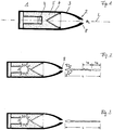
- the penetrator has an opening 8 with the diameter ⁇ L in the tip 2 of the penetrator 1 , as shown in FIG FIG. 1 is shown.
- the diameter ⁇ L of the opening 8 is based on the diameter ⁇ of the generated S spine S.
- the barbed diameters are in the same order of magnitude as the wall thickness of the hollow charge insert 6, which in turn is usually about 2-4% of the HL caliber (the funnel diameter at the base, ie at the largest point of the funnel diameter). Typical orders of magnitude are about 3 mm for a HL caliber of 100 mm. The barbed diameter is therefore about 3 - 5 mm in size for such a HL caliber in the final phase, and even slightly larger in the extension phase until the spiked particle is broken down (decomposition into individual particles).
- the posterior part of the spine is usually slightly thicker than the spiked tip.
- the opening 8 should therefore be sufficiently dimensioned to take account of all these barbed features and to further avoid potential spike disturbances when passing through the opening. In FIG. 2 this situation is shown with a too small opening 8 in the top 2.
- Sizes of the diameter of about 5 to 10 times the diameter of the spine S are considered sufficient - in the example, therefore, about 20 to 30 mm.
- This opening 8 prevents barbed parts are eroded or disturbed, the entire length of spikes L thus contributes to HL performance as in FIG. 3 is shown. If the perforation requirements on the penetrator (the target hardness and thickness in the target list) are not too high, then you can extend the safety margin a bit, in other words increase the opening 8 in the tip 2 a bit to be on the safe side lie, if it should also come to slight asymmetries of the spine S (spiky curvature) - what u. U. may occur in not exactly symmetrical shaped hollow charges, or here by the not completely symmetrical rupture of the shell in the detonation.
- FIG. 4 create closures 9 (screws, plugs and the like) of low-density material such as plastic ( FIG. 5 ) Remedy.
- the hollow charge is needed and for the second, the penetrator, which on the one hand to penetrate and on the other then inside to act as pressure and splinter charge.
- the performance increase of the hollow charge due to the opening 8 in the penetrator tip 2 is therefore intended only for hard and semi-hard targets in open space.
- the hollow charge power is not needed, but only the pressure and splintering effect of the penetrator.
- the formation of the shaped charge spine S is usually even undesirable, since you have goals in structures (if any HL targets are present, which should not be the case) with the sting anyway, at most randomly - so very rarely - would meet.
- this sting would perforate building walls relatively easily and thus leave the building again, which u. It could cause things outside the building to be hit (collateral targets) - which is highly undesirable. This danger exists in particular in so-called MOUT scenarios (Military Operations in Urban Terrains), where non-military items are often packed tightly packed.
- the closure is designed specifically to damage the HL insert in a more controlled manner and thus to ensure that the barbed power sufficiently reduced, and the formation of the spine S is securely suppressed.
- a PELE rod penetration with increased lateral effect
- a PELE rod consists of a metal cup MB (eg made of aluminum), in the middle of which a compressible expansion medium AWM (eg plastics such as PE etc.) is integrated.
- AWM eg plastics such as PE etc.
- FIG. 7 is shown in the target perforation of this expansion medium AWM compressed by the target material and thereby exerts a compression pressure on the metal cup MB, which then widens and decomposed into chips.
- FIG. 6 an opening 8 is sketched, which is closed with such a PELE stopper.
- the diameter ⁇ L of the opening 8 should in this case be increased by twice the wall thickness of the Al shell (shell wall thickness about 1 - 2 mm), in order to prevent the sting S with the denser material on the shell 3 in Touch comes.
- the plug must have sufficient friction in the opening 8 to allow sufficient compression pressure to build up. This can be achieved by measures such as gluing, roughening the surfaces, threads and the like.
- the successive lateral expansion in the target passage is in FIG. 7 in three time steps t 1 , t 2 , t 3 indicated.
- the PELE plug AWM, MB is accelerated into the interior 7 of the penetrator and the compression pressure of the AWM (here with plastic filling) widens the metal cup MB.
- this finally disassembles and thereby generates splinters SP, which fly laterally apart and large area - act together with the AWM plug - the shaped charge insert 6 and severely damage.
- the barbed power is reduced as desired in a controlled manner or completely suppressed.
- AWM thus combine two positive properties with each other: the barbed power is increased where needed and reduced / suppressed where not needed.
Landscapes
- Engineering & Computer Science (AREA)
- Chemical & Material Sciences (AREA)
- Combustion & Propulsion (AREA)
- General Engineering & Computer Science (AREA)
- Portable Nailing Machines And Staplers (AREA)
- Adjustment And Processing Of Grains (AREA)
Description
- Die Erfindung betrifft einen Penetrator (1) mit einer zumindest im Bereich der Spitze (2) verstärkten Hülle (3) und einer in der Spitze (2) des Penetrators (1) rotationssymmetrisch zur Längsachse (L) des Penetrators angeordneten Öffnung (8), die mittels eines entfernbaren Stopfens (9) verschließbar ist, der einen Becher bildet, dessen Boden einer Hohlladungseinlage zugewandt ist,
Aus derDE 202009015942 U1 ist ein Penetrator gemäß dem Oberbegriff der Patentanmeldung bekannt geworden. Im Inneren der Hülle ist eine Hohlladung bestehend aus einer Zündeinrichtung, einer Sprengladung und einer Einlage angeordnet. Bei Initiierung der Sprengladung erzeugt die Einlage einen Stachel, der sich im Hohlraum vor der Hohlladung ausbilden kann, sich in Richtung der Längsachse des Penetrators beschleunigt und schließlich die Spitze der Hülle des Penetrators durchbricht. Die aufgezeigte Lösung ist geeignet, bei besonderes hartem Aufprall und einem nicht mehr vermeidbaren Umstülpen der Einlage immer noch die initiierung der Sprengladung zu ermöglichen. - In der
EP 0 950 870 A2 wird ein Penetrator mit einer zumindest im Bereich der Spitze verstärkten Hülle beschrieben, der eine Hohlladungs-Sprengladung aufweist, deren Durchmesser an der Basis das Kaliber der Hohlldung bestimmt und die mittels eines Hohlraums von der Spitze des Penetrators beabstandet ist. - Die
US 2005/0223930 A1 beschreibt einen anderen Penetrator mit Hohlladung. Es ist deshalb Aufgabe der Erfindung die Leistung des Hohlladungsstachels kontrolliert zu reduzieren um damit die Sprengwirkung im Ziel zu verbessern. - Die Aufgabe wird durch einen Penetrator nach dem Anspruch 1 gelöst. Die erfindungsgemäße Lösung besteht darin, dass die Öffnung in der Spitze des Penetrators mittels eines Kunststoffpfropfens (AWM) verschlossen ist, der von einem Metallbecher (MB) umgeben ist, dessen Boden der Einlage (6) zugewandt ist, wobei in vorteilhafter Weise der Durchmesser der Öffnung 10 - 40 % des Kalibers der Hohlladung beträgt.
- Dabei ist es günstig, wenn der Durchmesser der Öffnung um wenigstens die doppelte Wandstärke des Metallbechers erweitert ist. Ein weiterer Vorteil wird erzielt, wenn der Metallbecher mit der Hülle lösbar verbunden ist.
- Durch die geschlossene und in der Regel relativ massiv ausgeführte Spitze der Penetratorhülle wird bei Zündung der Hohlladung und der anschließenden Perforation der massiven Nase zum einen ein Teil des Stachels verbraucht und zum anderen der daran anschließende Stachelteil mehr oder weniger stark gestört, da das durch den Stachel in der Spitze erzeugte Loch nicht ausreichend groß ist. Dadurch büßt der Hohlladungsstachel einen erheblichen Teil seiner Gesamtlänge ein, wodurch sich die Hohlladungsleistung im Ziel, - die erreichbare Zielkratertiefe - beträchtlich reduziert, da diese Kratertiefe direkt proportional zur Stachellänge ist.
- Ausführungsbeispiele von Penetratoren sind in der Zeichnung schematisch vereinfacht dargestellt und werden im Folgenden näher beschrieben. Es zeigen:
-
Fig. 1 : einen Hohlladungspenetrator mit Öffnung in der Spitze, -
Fig. 2 : den Leistungsverlust eines HL-Stachels bei Durchtritt durch die Spitze gemäß dem bisherigen Stand der Technik, -
Fig. 3 : den voll ausgebildeten Stachel mittels der Öffnung in der Spitze, -
Fig. 4 : ein Ausführungsbeispiel mit einem Sackloch in der Spitze. -
Fig. 5 : ein Ausführungsbeispiel mit einem Kunststoffpfropfen in der Öffnung, -
Fig. 6 : einen Verschluss der Öffnung mittels eines Metallbechers und einem Kunststoffpfropfen gemäß einem erfindungsgemäßen Ausführungsbeispiel, -
Fig. 7 : die Aufweitung und Zerlegung des Metallbechers beim Zielkontakt. - Der Penetrator weist in einem Ausführungsbeispiel eine Öffnung 8 mit dem Durchmesser ØL in der Spitze 2 des Penetrators 1 auf wie dies in
Figur 1 dargestellt ist. Der Durchmesser ØL dieser Öffnung 8 orientiert sich am Durchmesser ØS des erzeugten Stachels S. - Die Stacheldurchmesser sind in der gleichen Größenordnung wie die Wandstärke der Hohlladungs-Einlage 6, welche wiederum in der Regel ca. 2-4 % des HL-Kalibers (des Trichterdurchmessers an der Basis, also an der größten Stelle des Trichterdurchmessers) beträgt. Typische Größenordnungen sind etwa 3 mm für ein HL-Kaliber von 100 mm. Der Stacheldurchmesser ist also für ein solches HL-Kaliber in der Endphase etwa 3 - 5 mm groß, in der Streckungsphase bis zur Partikulation des Stachels (Zerlegung in Einzel-Partikel) noch etwas größer. Zudem ist der hintere Teil des Stachels in der Regel etwas dicker als die Stachelspitze.
- Die Öffnung 8 sollte also ausreichend dimensioniert sein, um all diesen Stacheleigenschaften Rechnung zu tragen und weiterhin um potenziell mögliche Stachelstörungen beim Passieren der Öffnung zu vermeiden. In
Figur 2 ist diese Situation bei einer zu kleinen Öffnung 8 in der Spitze 2 dargestellt. - Als ausreichend werden Größenordnungen des Durchmessers von ca. 5 - 10-mal des Durchmessers des Stachels S erachtet - im Beispiel also etwa 20 - 30 mm. Diese Öffnung 8 verhindert, dass Stachelteile erodiert bzw. gestört werden, die gesamte Stachellänge L trägt somit zur HL-Leistung bei wie dies in
Figur 3 dargestellt ist. Sind die Perforationsanforderungen an den Penetrator (die Zielhärte und -dicke in der Ziel-Liste) nicht zu hoch, so kann man die Sicherheitsmarge noch etwas erweitern, sprich die Öffnung 8 in der Spitze 2 noch etwas vergrößern, um so auf der sicheren Seite zu liegen, falls es überdies zu leichten Asymmetrien des Stachels S kommen sollte (Stachelkrümmung) - was u. U. bei nicht exakt symmetrisch gefertigten Hohlladungen, bzw. hier auch durch das nicht völlig symmetrische Aufreißen der Hülle bei der Detonation vorkommen kann. - Sowohl experimentelle Versuche, wie auch numerische Simulationen haben gezeigt, dass solche Öffnungen in der Spitze weder die Perforationsleistung im Ziel (Strukturen wie z.B. Gebäudewände), noch die Integrität der Penetrator-Hülle beim Zieldurchgang beeinträchtigen. Damit konnte demonstriert werden, dass neben der Leistungs-Steigerung der Hohlladung, keine unerwarteten Leistungs-Reduktionen beim Penetrator befürchtet werden müssen.
- Allerdings ist eine solche Öffnung 8 in der Penetratorspitze 2 für den operativen Einsatz (Lagerung, Transport etc.) einer solchen Penetrator-Hohlladung 1 eher nicht vorteilhaft, da dadurch in unerwünschter Weise Staub, Schmutz und andere Teile in den Hohlraum 7 der Hohlladung vor der Einlage 6 gelangen können. Diese wiederum können die Hohlladungs-Einlage 6 verschmutzen, beschädigen, oder den notwendigen Hohlraum 7 gar verstellen. All dies wäre für die HL-Leistung sehr abträglich.
- Gemäß
Figur 4 schaffen Verschlüsse 9 (Schrauben, Pfropfen und dergleichen mehr) aus niedrig-dichtem Material wie beispielsweise Kunststoff (Figur 5 ) Abhilfe. - Die typische Ziel-Liste einer solchen Penetrator-Hohlladung ist in der Regel zweigeteilt:
- Harte und halbharte Ziele im offenen Raum (z.B. gepanzerte Fahrzeuge).
- Strukturen (Häuser, Bunker etc.) die es zu perforieren gilt und deren Inneres außer Funktion gesetzt werden soll.
- Für die erste Kategorie wird die Hohlladung benötigt und für die zweite der Penetrator, der zum einen eindringen und zum anderen anschließend im Inneren als Druck- und Splitterladung wirken soll.
- Die Leistungssteigerung der Hohlladung infolge der Öffnung 8 in der Penetratorspitze 2 ist also lediglich für harte und halbharte Ziele im offenen Raum gedacht. Innerhalb von Strukturen (Häuser, Bunker etc.) wird die HohlladungsLeistung nicht benötigt, sondern nur die Druck- und Splitterwirkung des Penetrators. Im Gegenteil, innerhalb von Strukturen ist die Ausbildung des Hohlladungs-Stachels S in der Regel sogar ungewünscht, da man Ziele in Strukturen (falls überhaupt HL-Ziele vorhanden sind, was eher nicht der Fall sein sollte) mit dem Stachel sowieso höchstens zufällig - also sehr selten - treffen würde. Andererseits aber dieser Stachel Gebäudewände relativ leicht perforieren und damit das Gebäude wieder verlassen würde, was u. U. dazu führen könnte, dass Dinge außerhalb des Gebäudes getroffen werden könnten (Kollateralziele) - was höchst unerwünscht ist. Diese Gefahr besteht insbesondere in so genannten MOUT-Szenarien (Military Operations in Urban Terrains), wo häufig nichtmilitärische Dinge dicht-an-dicht gepackt sind.
- Bei relativ harten Strukturen - wie beispielsweise dicken Betonwänden - wird bei dessen Perforation der HL-Trichter durch die Vorwärtsbewegung der Sprengladung automatisch sehr stark deformiert, wodurch die Ausbildung eines leistungsfähigen Stachels verhindert wird. Bei dünneren Strukturen - wie beispielsweise dünnen Ziegelwänden - ist dies nicht notwendigerweise der Fall, da der Hohlladungs-Trichter selbst eine gewisse Abstützwirkung für die Sprengladung hervorruft. Dann bestände aber die größte Gefahr, da die Stachel-Perforation solch dünner Wände überdies keine starke Stachel-Erosion und damit keine große Leistungsreduzierung erwirken würde.
- Dieser Gefahr wirkt aber nun die vorgeschlagene Öffnung 8 in der Spitze 2 des Penetrators 1 in vorteilhafter Weise entgegen. Beim Zielkontakt wird etwa der oben vorgeschlagene Kunststoff-Pfropfen 9 (vgl.
Figur 5 ) geringer Dichte, bei der Wand-Perforation in das Penetrator-Innere gedrückt und in dessen Zuge weiterhin zusätzlich weitere Wandteile und anderes Zielmaterial. Diese Verunreinigungen bewirken nun aber genau den Effekt, der im o. g. Transport- und Lagerbetrieb erfolgreich verhindert werden sollte: nämlich die Verschmutzung, Beschädigung etc. der Hohlladungs-Einlage und somit die Leistungsreduktion des Stachels, bzw. der völligen Unterdrückung dessen Ausbildung. - Gemäß der Erfindung ist der Verschluss gezielt daraufhin ausgelegt, die HL-Einlage in mehr kontrollierter Weise zu beschädigen und somit sicher zu stellen, dass die Stachelleistung ausreichend reduziert, bzw. die Ausbildung des Stachels S sicher unterdrückt wird. Hierzu wird gemäß
Figur 6 ein Stopfen AWM, MB vorgeschlagen, der Aufbau und Funktion eines PELE-Stabes umfasst. Ein PELE-Stab (Penetration mit erhöhtem lateralem Effekt) besteht aus einem Metallbecher MB (z.B. aus Aluminium), in dessen Mitte ein kompressibles Aufweitmedium AWM (z.B. Kunststoffe wie PE etc.) integriert ist. Der Boden des Metallbechers ist dabei der Einlage 6 zugewandt. Wie inFigur 7 dargestellt wird bei der Ziel-Perforation dieses Aufweitmedium AWM durch das Zielmaterial komprimiert und übt dadurch einen Kompressions-Druck auf den Metallbecher MB aus, welcher sich daraufhin aufweitet und in Splitter zerlegt. Diese weisen nun auch in lateraler Richtung einen Geschwindigkeitsvektor auf. - In
Figur 6 ist eine Öffnung 8 skizziert, die mit einem derartigen PELE-Stopfen verschlossen ist. Der Durchmesser ØL der Öffnung 8 sollte hierbei um die doppelte Wandstärke der Al-Hülle (Hüllenwandstärke ca. 1 - 2 mm) vergrößert werden, um zu verhindern, dass der Stachel S mit dem dichteren Material an der Hülle 3 in Berührung kommt. Der Stopfen muss eine ausreichende Reibung in der Öffnung 8 aufweisen, damit sich ausreichender Kompressionsdruck aufbauen kann. Dies kann durch Maßnahmen wie Einkleben, Aufrauen der Oberflächen, Gewinde und dergleichen mehr erreicht werden. - Das sukzessive laterale Aufweiten beim Zieldurchgang ist in
Figur 7 in drei Zeitschritten t1, t2, t3 angedeutet. Der PELE-Stopfen AWM, MB wird in den Innenraum 7 des Penetrators beschleunigt und durch den Kompressionsdruck des AWM (hier mit Kunststofffüllung) weitet sich der Metallbecher MB auf. Im weiteren Verlauf zerlegt sich dieser schließlich und erzeugt dabei Splitter SP, die lateral auseinander fliegen und großflächig - gemeinsam mit dem AWM-Pfropfen - die Hohlladungs-Einlage 6 beaufschlagen und stark beschädigen. Die Stachelleistung wird so wie gewünscht in kontrollierter Weise reduziert oder gänzlich unterdrückt. - Die Öffnung 8 in der Spitze 2 des Penetrators 1 im Verbund mit dem Verschluss-Stopfen 9, AWM kombinieren somit zwei positive Eigenschaften miteinander: die Stachelleistung wird erhöht wo benötigt und verringert / unterdrückt wo nicht benötigt.
-
- 1
- Penetrator
- 2
- Spitze der Hülle
- 3
- Hülle
- 4
- Zündsystem
- 5
- Sprengladung
- 6
- Einlage
- 7
- Hohlraum vor Einlage
- 8
- Öffnung
- 9
- Stopfen
- 10
- Sackloch-Bohrung
- 11
- Steg
- AWM
- Aufweitmedium
- L
- gesamte Länge des Stachels
- LN
- Verlust aufgrund Perforation der Spitze
- LS
- Verlust aufgrund Störung an der Außenwand der Perforation
- MB
- Metallbecher
- ØL
- Durchmesser der Öffnung
- S
- Stachel
- SP
- Splitter
- t1...3
- Zeitpunkte 1 ... 3
- Z
- Ziel
Claims (4)
- Penetrator (1) mit einer zumindest im Bereich der Spitze (2) verstärkten Hülle (3) , mit einem heckseitig angeordneten Zündsystem (4), das mit einer Hohlladungs-Sprengladung (5) kooperiert, wobei die Hohlladungs-Sprengladung bugseitig mit einer Hohlladungseinlage (6) abgeschlossen ist, und einer in der Spitze (2) des Penetrators (1) rotationssymmetrisch zur Längsachse (L) des Penetrators angeordneten Öffnung (8),
dadurch gekennzeichnet,
dass die Öffnung (8) mittels eines Kunststoffpfropfens aus kompressiblem Aufweitmaterial (AWM) verschlossen ist, der von einem Metallbecher (MB) umgeben ist und der Boden des Metallbechers (MB) der Hohlladungseinlage (6) zugewandt ist. - Penetrator nach Anspruch 1, dadurch gekennzeichnet, dass der Durchmesser (ØL) der Öffnung (8) 10 - 40 % des Kalibers der Hohlladung beträgt.
- Penetrator nach Anspruch 1, dadurch gekennzeichnet, dass der Durchmesser (ØL) der Öffnung (8) um wenigstens die doppelte Wandstärke des Metallbechers (MB) erweitert ist.
- Penetrator nach Anspruch 1 oder 2, dadurch gekennzeichnet, dass der Metallbecher (MB) mit der Hülle (3) lösbar verbunden ist.
Applications Claiming Priority (2)
| Application Number | Priority Date | Filing Date | Title |
|---|---|---|---|
| DE102011010977 | 2011-02-10 | ||
| DE102011012850A DE102011012850A1 (de) | 2011-02-10 | 2011-03-03 | Hohlladungspenetrator |
Publications (3)
| Publication Number | Publication Date |
|---|---|
| EP2487451A2 EP2487451A2 (de) | 2012-08-15 |
| EP2487451A3 EP2487451A3 (de) | 2015-04-29 |
| EP2487451B1 true EP2487451B1 (de) | 2018-01-17 |
Family
ID=45606940
Family Applications (1)
| Application Number | Title | Priority Date | Filing Date |
|---|---|---|---|
| EP12000643.2A Active EP2487451B1 (de) | 2011-02-10 | 2012-02-02 | Hohlladungspenetrator |
Country Status (3)
| Country | Link |
|---|---|
| EP (1) | EP2487451B1 (de) |
| DE (1) | DE102011012850A1 (de) |
| ES (1) | ES2662352T3 (de) |
Family Cites Families (6)
| Publication number | Priority date | Publication date | Assignee | Title |
|---|---|---|---|---|
| NL135094C (de) * | 1961-01-05 | |||
| FR2310547A1 (fr) * | 1975-05-06 | 1976-12-03 | Realisa Et Applic Tech Et | Perfectionnements aux charges creuses |
| DE59907908D1 (de) * | 1998-04-18 | 2004-01-15 | Tdw Verteidigungstech Wirksys | Kombinationsgefechtskopf |
| US7418905B2 (en) * | 2003-12-19 | 2008-09-02 | Raytheon Company | Multi-mission payload system |
| DE102008023678B4 (de) | 2008-05-15 | 2012-11-29 | Diehl Bgt Defence Gmbh & Co. Kg | Fliegerbombe |
| DE202009015942U1 (de) | 2009-11-21 | 2010-02-25 | TDW Gesellschaft für verteidigungstechnische Wirksysteme mbH | Zündvorrichtung für die Sprengladung eines Penetrators |
-
2011
- 2011-03-03 DE DE102011012850A patent/DE102011012850A1/de not_active Ceased
-
2012
- 2012-02-02 EP EP12000643.2A patent/EP2487451B1/de active Active
- 2012-02-02 ES ES12000643.2T patent/ES2662352T3/es active Active
Non-Patent Citations (1)
| Title |
|---|
| None * |
Also Published As
| Publication number | Publication date |
|---|---|
| EP2487451A2 (de) | 2012-08-15 |
| DE102011012850A1 (de) | 2012-08-16 |
| ES2662352T3 (es) | 2018-04-06 |
| EP2487451A3 (de) | 2015-04-29 |
Similar Documents
| Publication | Publication Date | Title |
|---|---|---|
| EP1000311B1 (de) | Geschoss oder gefechtskopf | |
| DE3137855C2 (de) | ||
| DE3802002A1 (de) | Zuender- und sprengstoffloses geschoss fuer rohrwaffen | |
| EP2786089B1 (de) | Teilzerlegungsgeschoss oder zerlegungsgeschoss mit einem pb-freien kern durchzogen mit sollbruchstellen | |
| EP2807444B1 (de) | Schutzelement zum schutz gegen ballistische geschosse und militärisches fahrzeug | |
| EP0343389A1 (de) | Geschosskern für ein Treibspiegelgeschoss | |
| DE60037934T2 (de) | Mauerzerbrechender Gefechtskopf | |
| EP2719993A2 (de) | Expansions-Jagdgeschoss | |
| DE1910779C3 (de) | Hohlladung | |
| EP1196734B1 (de) | Teilzerlegungsgeschoss mit penetrator im geschossbug | |
| DE102004035385A1 (de) | Teilzerlegungsgeschoss mit massivem Kern und Kern aus gepresstem Pulver | |
| DE10045009A1 (de) | Jagdbüchsengeschoß mit zusätzlich gekapseltem Kern | |
| EP2024706A1 (de) | Geschoss, wirkkörper oder gefechtskopf zur bekämpfung massiver, strukturierter und flächenhafter ziele | |
| WO2001002791A2 (de) | Deformationsgeschoss | |
| EP0950870A2 (de) | Kombinationsgefechtskopf | |
| DE202012010484U1 (de) | Geschoss mit verringertem Penetrationsvermögen | |
| WO2021164961A1 (de) | Penetrator und verwendung eines penetrators | |
| EP2487451A2 (de) | Hohlladungspenetrator | |
| EP3742106A1 (de) | Penetrator, verwendung eines penetrators und geschoss | |
| DE10201191B4 (de) | System zur Erzeugung der Reaktion einer Munition | |
| DE69611273T2 (de) | Asymmetrisches Penetratorgeschoss | |
| WO2018219686A1 (de) | Geschoss mit aufweitmedium | |
| DE10130324B4 (de) | Splittererzeugender Gefechtskopf | |
| DE10129227B4 (de) | Hohlladung | |
| EP1656533A1 (de) | Teilzerlegungsgeschoss mit massivem kern und kern aus gepresstem pulver |
Legal Events
| Date | Code | Title | Description |
|---|---|---|---|
| PUAI | Public reference made under article 153(3) epc to a published international application that has entered the european phase |
Free format text: ORIGINAL CODE: 0009012 |
|
| AK | Designated contracting states |
Kind code of ref document: A2 Designated state(s): AL AT BE BG CH CY CZ DE DK EE ES FI FR GB GR HR HU IE IS IT LI LT LU LV MC MK MT NL NO PL PT RO RS SE SI SK SM TR |
|
| AX | Request for extension of the european patent |
Extension state: BA ME |
|
| PUAL | Search report despatched |
Free format text: ORIGINAL CODE: 0009013 |
|
| AK | Designated contracting states |
Kind code of ref document: A3 Designated state(s): AL AT BE BG CH CY CZ DE DK EE ES FI FR GB GR HR HU IE IS IT LI LT LU LV MC MK MT NL NO PL PT RO RS SE SI SK SM TR |
|
| AX | Request for extension of the european patent |
Extension state: BA ME |
|
| RIC1 | Information provided on ipc code assigned before grant |
Ipc: F42B 12/10 20060101AFI20150325BHEP |
|
| 17P | Request for examination filed |
Effective date: 20150803 |
|
| STAA | Information on the status of an ep patent application or granted ep patent |
Free format text: STATUS: EXAMINATION IS IN PROGRESS |
|
| 17Q | First examination report despatched |
Effective date: 20161121 |
|
| GRAP | Despatch of communication of intention to grant a patent |
Free format text: ORIGINAL CODE: EPIDOSNIGR1 |
|
| STAA | Information on the status of an ep patent application or granted ep patent |
Free format text: STATUS: GRANT OF PATENT IS INTENDED |
|
| INTG | Intention to grant announced |
Effective date: 20171109 |
|
| GRAS | Grant fee paid |
Free format text: ORIGINAL CODE: EPIDOSNIGR3 |
|
| GRAA | (expected) grant |
Free format text: ORIGINAL CODE: 0009210 |
|
| STAA | Information on the status of an ep patent application or granted ep patent |
Free format text: STATUS: THE PATENT HAS BEEN GRANTED |
|
| AK | Designated contracting states |
Kind code of ref document: B1 Designated state(s): AL AT BE BG CH CY CZ DE DK EE ES FI FR GB GR HR HU IE IS IT LI LT LU LV MC MK MT NL NO PL PT RO RS SE SI SK SM TR |
|
| REG | Reference to a national code |
Ref country code: GB Ref legal event code: FG4D Free format text: NOT ENGLISH |
|
| REG | Reference to a national code |
Ref country code: CH Ref legal event code: EP |
|
| REG | Reference to a national code |
Ref country code: IE Ref legal event code: FG4D Free format text: LANGUAGE OF EP DOCUMENT: GERMAN |
|
| REG | Reference to a national code |
Ref country code: AT Ref legal event code: REF Ref document number: 964716 Country of ref document: AT Kind code of ref document: T Effective date: 20180215 |
|
| REG | Reference to a national code |
Ref country code: DE Ref legal event code: R096 Ref document number: 502012012009 Country of ref document: DE |
|
| REG | Reference to a national code |
Ref country code: FR Ref legal event code: PLFP Year of fee payment: 7 |
|
| REG | Reference to a national code |
Ref country code: ES Ref legal event code: FG2A Ref document number: 2662352 Country of ref document: ES Kind code of ref document: T3 Effective date: 20180406 |
|
| REG | Reference to a national code |
Ref country code: NL Ref legal event code: MP Effective date: 20180117 |
|
| REG | Reference to a national code |
Ref country code: LT Ref legal event code: MG4D |
|
| PG25 | Lapsed in a contracting state [announced via postgrant information from national office to epo] |
Ref country code: NL Free format text: LAPSE BECAUSE OF FAILURE TO SUBMIT A TRANSLATION OF THE DESCRIPTION OR TO PAY THE FEE WITHIN THE PRESCRIBED TIME-LIMIT Effective date: 20180117 |
|
| PG25 | Lapsed in a contracting state [announced via postgrant information from national office to epo] |
Ref country code: HR Free format text: LAPSE BECAUSE OF FAILURE TO SUBMIT A TRANSLATION OF THE DESCRIPTION OR TO PAY THE FEE WITHIN THE PRESCRIBED TIME-LIMIT Effective date: 20180117 Ref country code: CY Free format text: LAPSE BECAUSE OF FAILURE TO SUBMIT A TRANSLATION OF THE DESCRIPTION OR TO PAY THE FEE WITHIN THE PRESCRIBED TIME-LIMIT Effective date: 20180117 Ref country code: FI Free format text: LAPSE BECAUSE OF FAILURE TO SUBMIT A TRANSLATION OF THE DESCRIPTION OR TO PAY THE FEE WITHIN THE PRESCRIBED TIME-LIMIT Effective date: 20180117 Ref country code: NO Free format text: LAPSE BECAUSE OF FAILURE TO SUBMIT A TRANSLATION OF THE DESCRIPTION OR TO PAY THE FEE WITHIN THE PRESCRIBED TIME-LIMIT Effective date: 20180417 Ref country code: LT Free format text: LAPSE BECAUSE OF FAILURE TO SUBMIT A TRANSLATION OF THE DESCRIPTION OR TO PAY THE FEE WITHIN THE PRESCRIBED TIME-LIMIT Effective date: 20180117 |
|
| PG25 | Lapsed in a contracting state [announced via postgrant information from national office to epo] |
Ref country code: LV Free format text: LAPSE BECAUSE OF FAILURE TO SUBMIT A TRANSLATION OF THE DESCRIPTION OR TO PAY THE FEE WITHIN THE PRESCRIBED TIME-LIMIT Effective date: 20180117 Ref country code: SE Free format text: LAPSE BECAUSE OF FAILURE TO SUBMIT A TRANSLATION OF THE DESCRIPTION OR TO PAY THE FEE WITHIN THE PRESCRIBED TIME-LIMIT Effective date: 20180117 Ref country code: RS Free format text: LAPSE BECAUSE OF FAILURE TO SUBMIT A TRANSLATION OF THE DESCRIPTION OR TO PAY THE FEE WITHIN THE PRESCRIBED TIME-LIMIT Effective date: 20180117 Ref country code: BG Free format text: LAPSE BECAUSE OF FAILURE TO SUBMIT A TRANSLATION OF THE DESCRIPTION OR TO PAY THE FEE WITHIN THE PRESCRIBED TIME-LIMIT Effective date: 20180417 Ref country code: GR Free format text: LAPSE BECAUSE OF FAILURE TO SUBMIT A TRANSLATION OF THE DESCRIPTION OR TO PAY THE FEE WITHIN THE PRESCRIBED TIME-LIMIT Effective date: 20180418 Ref country code: IS Free format text: LAPSE BECAUSE OF FAILURE TO SUBMIT A TRANSLATION OF THE DESCRIPTION OR TO PAY THE FEE WITHIN THE PRESCRIBED TIME-LIMIT Effective date: 20180517 Ref country code: PL Free format text: LAPSE BECAUSE OF FAILURE TO SUBMIT A TRANSLATION OF THE DESCRIPTION OR TO PAY THE FEE WITHIN THE PRESCRIBED TIME-LIMIT Effective date: 20180117 |
|
| REG | Reference to a national code |
Ref country code: CH Ref legal event code: PL |
|
| PG25 | Lapsed in a contracting state [announced via postgrant information from national office to epo] |
Ref country code: MT Free format text: LAPSE BECAUSE OF FAILURE TO SUBMIT A TRANSLATION OF THE DESCRIPTION OR TO PAY THE FEE WITHIN THE PRESCRIBED TIME-LIMIT Effective date: 20180117 |
|
| REG | Reference to a national code |
Ref country code: DE Ref legal event code: R097 Ref document number: 502012012009 Country of ref document: DE |
|
| PG25 | Lapsed in a contracting state [announced via postgrant information from national office to epo] |
Ref country code: RO Free format text: LAPSE BECAUSE OF FAILURE TO SUBMIT A TRANSLATION OF THE DESCRIPTION OR TO PAY THE FEE WITHIN THE PRESCRIBED TIME-LIMIT Effective date: 20180117 Ref country code: EE Free format text: LAPSE BECAUSE OF FAILURE TO SUBMIT A TRANSLATION OF THE DESCRIPTION OR TO PAY THE FEE WITHIN THE PRESCRIBED TIME-LIMIT Effective date: 20180117 Ref country code: AL Free format text: LAPSE BECAUSE OF FAILURE TO SUBMIT A TRANSLATION OF THE DESCRIPTION OR TO PAY THE FEE WITHIN THE PRESCRIBED TIME-LIMIT Effective date: 20180117 Ref country code: MC Free format text: LAPSE BECAUSE OF FAILURE TO SUBMIT A TRANSLATION OF THE DESCRIPTION OR TO PAY THE FEE WITHIN THE PRESCRIBED TIME-LIMIT Effective date: 20180117 |
|
| PLBE | No opposition filed within time limit |
Free format text: ORIGINAL CODE: 0009261 |
|
| STAA | Information on the status of an ep patent application or granted ep patent |
Free format text: STATUS: NO OPPOSITION FILED WITHIN TIME LIMIT |
|
| REG | Reference to a national code |
Ref country code: IE Ref legal event code: MM4A |
|
| REG | Reference to a national code |
Ref country code: BE Ref legal event code: MM Effective date: 20180228 |
|
| PG25 | Lapsed in a contracting state [announced via postgrant information from national office to epo] |
Ref country code: CH Free format text: LAPSE BECAUSE OF NON-PAYMENT OF DUE FEES Effective date: 20180228 Ref country code: SM Free format text: LAPSE BECAUSE OF FAILURE TO SUBMIT A TRANSLATION OF THE DESCRIPTION OR TO PAY THE FEE WITHIN THE PRESCRIBED TIME-LIMIT Effective date: 20180117 Ref country code: DK Free format text: LAPSE BECAUSE OF FAILURE TO SUBMIT A TRANSLATION OF THE DESCRIPTION OR TO PAY THE FEE WITHIN THE PRESCRIBED TIME-LIMIT Effective date: 20180117 Ref country code: LU Free format text: LAPSE BECAUSE OF NON-PAYMENT OF DUE FEES Effective date: 20180202 Ref country code: SK Free format text: LAPSE BECAUSE OF FAILURE TO SUBMIT A TRANSLATION OF THE DESCRIPTION OR TO PAY THE FEE WITHIN THE PRESCRIBED TIME-LIMIT Effective date: 20180117 Ref country code: LI Free format text: LAPSE BECAUSE OF NON-PAYMENT OF DUE FEES Effective date: 20180228 Ref country code: CZ Free format text: LAPSE BECAUSE OF FAILURE TO SUBMIT A TRANSLATION OF THE DESCRIPTION OR TO PAY THE FEE WITHIN THE PRESCRIBED TIME-LIMIT Effective date: 20180117 |
|
| 26N | No opposition filed |
Effective date: 20181018 |
|
| PG25 | Lapsed in a contracting state [announced via postgrant information from national office to epo] |
Ref country code: IE Free format text: LAPSE BECAUSE OF NON-PAYMENT OF DUE FEES Effective date: 20180202 |
|
| PG25 | Lapsed in a contracting state [announced via postgrant information from national office to epo] |
Ref country code: SI Free format text: LAPSE BECAUSE OF FAILURE TO SUBMIT A TRANSLATION OF THE DESCRIPTION OR TO PAY THE FEE WITHIN THE PRESCRIBED TIME-LIMIT Effective date: 20180117 Ref country code: BE Free format text: LAPSE BECAUSE OF NON-PAYMENT OF DUE FEES Effective date: 20180228 |
|
| REG | Reference to a national code |
Ref country code: AT Ref legal event code: MM01 Ref document number: 964716 Country of ref document: AT Kind code of ref document: T Effective date: 20180202 |
|
| PG25 | Lapsed in a contracting state [announced via postgrant information from national office to epo] |
Ref country code: AT Free format text: LAPSE BECAUSE OF NON-PAYMENT OF DUE FEES Effective date: 20180202 |
|
| PG25 | Lapsed in a contracting state [announced via postgrant information from national office to epo] |
Ref country code: TR Free format text: LAPSE BECAUSE OF FAILURE TO SUBMIT A TRANSLATION OF THE DESCRIPTION OR TO PAY THE FEE WITHIN THE PRESCRIBED TIME-LIMIT Effective date: 20180117 |
|
| PGFP | Annual fee paid to national office [announced via postgrant information from national office to epo] |
Ref country code: ES Payment date: 20200322 Year of fee payment: 9 Ref country code: IT Payment date: 20200225 Year of fee payment: 9 |
|
| PG25 | Lapsed in a contracting state [announced via postgrant information from national office to epo] |
Ref country code: HU Free format text: LAPSE BECAUSE OF FAILURE TO SUBMIT A TRANSLATION OF THE DESCRIPTION OR TO PAY THE FEE WITHIN THE PRESCRIBED TIME-LIMIT; INVALID AB INITIO Effective date: 20120202 Ref country code: PT Free format text: LAPSE BECAUSE OF FAILURE TO SUBMIT A TRANSLATION OF THE DESCRIPTION OR TO PAY THE FEE WITHIN THE PRESCRIBED TIME-LIMIT Effective date: 20180117 |
|
| PG25 | Lapsed in a contracting state [announced via postgrant information from national office to epo] |
Ref country code: MK Free format text: LAPSE BECAUSE OF NON-PAYMENT OF DUE FEES Effective date: 20180117 |
|
| PG25 | Lapsed in a contracting state [announced via postgrant information from national office to epo] |
Ref country code: IT Free format text: LAPSE BECAUSE OF NON-PAYMENT OF DUE FEES Effective date: 20210202 |
|
| REG | Reference to a national code |
Ref country code: ES Ref legal event code: FD2A Effective date: 20220504 |
|
| PG25 | Lapsed in a contracting state [announced via postgrant information from national office to epo] |
Ref country code: ES Free format text: LAPSE BECAUSE OF NON-PAYMENT OF DUE FEES Effective date: 20210203 |
|
| PGFP | Annual fee paid to national office [announced via postgrant information from national office to epo] |
Ref country code: GB Payment date: 20260219 Year of fee payment: 15 |
|
| PGFP | Annual fee paid to national office [announced via postgrant information from national office to epo] |
Ref country code: DE Payment date: 20260227 Year of fee payment: 15 |
|
| PGFP | Annual fee paid to national office [announced via postgrant information from national office to epo] |
Ref country code: FR Payment date: 20260218 Year of fee payment: 15 |