EP2486787B1 - Dispositif destiné à supprimer des éléments de plantes d'une aide à la croissance - Google Patents
Dispositif destiné à supprimer des éléments de plantes d'une aide à la croissance Download PDFInfo
- Publication number
- EP2486787B1 EP2486787B1 EP11001169.9A EP11001169A EP2486787B1 EP 2486787 B1 EP2486787 B1 EP 2486787B1 EP 11001169 A EP11001169 A EP 11001169A EP 2486787 B1 EP2486787 B1 EP 2486787B1
- Authority
- EP
- European Patent Office
- Prior art keywords
- intake
- elements
- plant
- wheel
- shaft
- Prior art date
- Legal status (The legal status is an assumption and is not a legal conclusion. Google has not performed a legal analysis and makes no representation as to the accuracy of the status listed.)
- Active
Links
- 238000000034 method Methods 0.000 title description 10
- 230000009194 climbing Effects 0.000 title 1
- 230000033001 locomotion Effects 0.000 claims description 36
- 230000006835 compression Effects 0.000 claims description 21
- 238000007906 compression Methods 0.000 claims description 21
- 230000007423 decrease Effects 0.000 claims description 3
- 241000196324 Embryophyta Species 0.000 description 246
- 238000011835 investigation Methods 0.000 description 14
- 238000013461 design Methods 0.000 description 8
- 230000015572 biosynthetic process Effects 0.000 description 7
- 238000005755 formation reaction Methods 0.000 description 7
- 230000006378 damage Effects 0.000 description 6
- 235000014787 Vitis vinifera Nutrition 0.000 description 5
- 240000006365 Vitis vinifera Species 0.000 description 5
- 238000009369 viticulture Methods 0.000 description 5
- 230000002829 reductive effect Effects 0.000 description 4
- 230000003247 decreasing effect Effects 0.000 description 3
- 238000001514 detection method Methods 0.000 description 3
- 238000006073 displacement reaction Methods 0.000 description 3
- 230000000694 effects Effects 0.000 description 3
- 238000009825 accumulation Methods 0.000 description 2
- 239000003795 chemical substances by application Substances 0.000 description 2
- 230000001788 irregular Effects 0.000 description 2
- 238000012423 maintenance Methods 0.000 description 2
- 239000002184 metal Substances 0.000 description 2
- 230000000149 penetrating effect Effects 0.000 description 2
- 238000000926 separation method Methods 0.000 description 2
- 208000027418 Wounds and injury Diseases 0.000 description 1
- 230000001464 adherent effect Effects 0.000 description 1
- 230000002411 adverse Effects 0.000 description 1
- 238000011161 development Methods 0.000 description 1
- 208000014674 injury Diseases 0.000 description 1
- 230000000670 limiting effect Effects 0.000 description 1
- 238000003754 machining Methods 0.000 description 1
- 238000005457 optimization Methods 0.000 description 1
- 230000036961 partial effect Effects 0.000 description 1
- 238000013138 pruning Methods 0.000 description 1
- 238000012549 training Methods 0.000 description 1
- 239000006163 transport media Substances 0.000 description 1
- 238000004804 winding Methods 0.000 description 1
Images


Classifications
-
- A—HUMAN NECESSITIES
- A01—AGRICULTURE; FORESTRY; ANIMAL HUSBANDRY; HUNTING; TRAPPING; FISHING
- A01G—HORTICULTURE; CULTIVATION OF VEGETABLES, FLOWERS, RICE, FRUIT, VINES, HOPS OR SEAWEED; FORESTRY; WATERING
- A01G17/00—Cultivation of hops, vines, fruit trees, or like trees
- A01G17/02—Cultivation of hops or vines
-
- A—HUMAN NECESSITIES
- A01—AGRICULTURE; FORESTRY; ANIMAL HUSBANDRY; HUNTING; TRAPPING; FISHING
- A01G—HORTICULTURE; CULTIVATION OF VEGETABLES, FLOWERS, RICE, FRUIT, VINES, HOPS OR SEAWEED; FORESTRY; WATERING
- A01G3/00—Cutting implements specially adapted for horticultural purposes; Delimbing standing trees
- A01G3/04—Apparatus for trimming hedges, e.g. hedge shears
- A01G3/0408—Apparatus for trimming hedges, e.g. hedge shears specially adapted for trellis work, e.g. machines for pruning vine or the like
Definitions
- the invention relates to a device for removing parts of plants from at least one elongated, karstabilen, limp growth aid during movement of the device along the growth aid according to the preamble of claim 1.
- pliable growth aids such as ropes or wires are known to support the plants and / or to influence the growth of the plants.
- pliable growth aids such as ropes or wires
- the use of trellis wires is known, for example in Guyot and also in cordon education.
- WO 2009/051498 A2 an apparatus and a method for removing parts of plants from a growth aid is known, wherein adhering to the growth aid plant parts are compressed by means of a plant supply unit and / or supplied to a detaching unit.
- the detaching unit comprises at least one detaching element, such as a rotating cutting blade, by means of which the plant parts are at least partially detached from the growth aid.
- the growth aid is guided during the machining process by means of a growth aid guide in order to avoid in particular damage to the growth aid guide by the detachment element.
- the plant parts can grow irregularly and in particular after cutting off the main plant in different directions and in different lengths of the growth aid can stand so high demands on the method and device for removing consist of all the forms of plant parts.
- the plant parts can by wrapping and / or ramifications have a stable connection with the growth aid, which is difficult to solve.
- the present invention is therefore based on the object to improve the prior art devices and methods for removing parts of plants from a growth aid and to reduce the susceptibility to errors and the resulting interruptions during operation.
- the device according to the invention for removing parts of plants from at least one elongated, tensile stable, non-limp growth aid during a movement of the device along the growth aid comprises a growth aid guide for guiding the growth aid during the movement of the device along the growth aid. Furthermore, the device comprises a detachment unit. The apparatus further comprises a plant guide unit for compressing and / or feeding the plant parts adhering to the growth aid to the detachment unit.
- the detachment unit comprises at least one detachment element, which detachment element is movably arranged on the device in such a way that, when operated by movement of the detachment element, plant parts are at least partially detachable from the growth aid.
- the plant management unit comprises at least one rotatably arranged feed wheel for feeding in and / or for compressing the plant parts.
- the plant management unit comprises a plurality of intake elements.
- Each of the plurality of intake elements is movable and a real or imaginary lateral surface of the Einzugsrades penetrating arranged such that upon rotation of the Einzugsrades the intake element in a forward position with respect to the direction of movement of the device further protrudes from the lateral surface than in a rearward position.
- the lateral surface of the feed wheel substantially closed with recesses for the intake elements. In this case, one can speak of a real lateral surface. It is also within the scope of the invention that the lateral surface of the feed wheel has one or more recesses, for example formed by individual elements such as rods along the circumference of the Einzugsrades. In such cases, the lateral surface is the smallest envelope of the feed wheel and thus represents an imaginary lateral surface.
- each of the plurality of catchment elements in a forward position with respect to the direction of movement of the device protrudes further from the lateral surface than in a position to the rear.
- the feeder elements further protrude from the lateral surface and thus an efficient detection is ensured and in the rear area of the feed wheel, in which the Plant parts are already compressed or made suitable for feeding to the detaching unit, the catchment elements protrude less far out of the lateral surface, so that an adverse effect on the plant parts and the growth aid is excluded as described above.
- the ratio between the operating and maintenance period of the device according to the invention is significantly improved and thus increases the efficiency.
- the feed wheel and the plurality of intake elements are designed such that, in the forward position, the intake elements protrude from the outer surface by a length which is greater by at least a factor of two than in FIG Position to the rear, preferably by at least a factor of 3, more preferably by at least a factor of 5.
- each of the plurality of intake elements is rotatably arranged with a rotation axis perpendicular to a longitudinal extent of the intake element.
- all catchment elements are arranged rotatably about a common axis of rotation, wherein preferably the plurality of catchment elements offset in the axial direction of their common axis of rotation, preferably arranged side by side.
- the above-mentioned guidance of the intake elements by the intake wheel is preferably formed in that the lateral surface of the Einzugsrades has recesses through which extend the intake elements, so that a rotational movement of the wheel is transmitted to the respective intake element by the edge of the recess.
- a structurally simple and robust embodiment in particular, the above-described different lengths of the protrusion of the feeder elements is guaranteed depending on the position of the feeder elements, results in a preferred embodiment in which the axis of rotation of each of the plurality of Einzugss instituten parallel to the axis of rotation of Einzugsrades is, wherein preferably the axis of rotation of each of the plurality of catchment elements is spaced from the axis of rotation of the Einzugsrades.
- the axis of rotation of each of the plurality of catch elements is preferably arranged at least in the direction of movement of the device forwardly spaced from the axis of rotation of the Einzugsrades.
- each of the plurality of intake elements is advantageous to arrange the axis of rotation of each of the plurality of intake elements at least in a direction away from a compression region of the Einzugsrades direction spaced from the axis of rotation of the Einzugsrades, in particular to combine both aforementioned spacings.
- the plant management unit of the device according to the invention has a counter element to the feed wheel, so that between the feed wheel and counter element a compression takes place at least irregularly from the plant growing parts protruding from the growth aid.
- the plant management unit is designed such that each of the plurality of intake elements does not touch the counter element regardless of the position of the intake element. In order nevertheless to ensure a sufficiently broad protrusion of the catchment elements in the direction of movement of the device in front region of the feed wheel, it is advantageous to provide in addition to the aforementioned spacing to the front and a spacing in the opposite direction of the position of the compression region.
- the feeder elements are arranged in groups in the axial direction of their axis of rotation. This means that in axial projection, the intake elements of a group always have the same position.
- groups of two i. H. to group the feeder elements in pairs in the axial direction of their axis of rotation.
- the device according to the invention such that the growth aid in operation between the intake elements of a Group runs so that at least one catchment element right and a catchment element left of the growth aid ensures the entry of the plants.
- the groups have an increasing distance of the feeder elements in the axial direction. This means that when viewing a rotating feed wheel from the front, the distance between two successive feeder elements is reduced to jump back to the maximum distance after a complete rotation. In this view, this results in a V-shaped merging of the intake elements when viewing a rotating feed wheel from the front, which can already exert a compression function on the plant parts.
- the growth aid in which in addition the growth aid is guided between the intake elements of a group advantageous that centered by the above each approaching the feeder elements in the axial direction, the growth aid with each complete rotation of the feed wheel in the central region of the feeder elements with the smallest distance becomes. As a result, a slipping out or a displacement of the growth aid can thus be corrected perpendicular to the longitudinal extent of the growth aid.
- the plant guide unit of the device according to the invention preferably has a counter element to the feed wheel, which is arranged to form a compression region for the plant parts between the feed wheel and the counter element.
- the counter element in a structurally simple manner, for example as a surface, in particular as a sheet.
- the counter-element form as Gegeneinzugsrad.
- the Schmidteinzugsrad preferably has a parallel to the feed wheel axis of rotation and is preferably driven in opposite directions to the feed wheel.
- the catchment elements in the compression area come close to the counter-engagement wheel, but do not touch it.
- the plurality of intake elements have a distance in the range of 1 cm to 20 cm, preferably in the range of 1 cm to 10 cm, more preferably in the range of 1 cm to 5 cm to the counter element in the compression region.
- the counter element as Gegeneinzugsrad it is advantageous to form the Gegeneinzugsrad barrel-shaped with a decreasing in the axial direction outward radius and the axial direction more spaced catch elements with a greater length than the less widely spaced catchment elements each one group.
- the decreasing outwardly radius of Gegeneinzugsrades is compensated by the greater length of the outer intake elements, so that there is approximately a constant distance between intake element and surface of Schmidteinzugsrades, regardless of the distance between the intake elements.
- the plurality of intake elements at the opposite end of the direction of the device compression end of the device by less than 5 cm, preferably by less than 3 cm, more preferably not protrude from the lateral surface of the Einzugsrades.
- the growth aid in the compression region of the feed wheel in the axial direction is approximately in the middle.
- the feed wheel has an approximately centrally in the axial direction guide for a growth aid.
- Such a guide may be formed for example by a wedge or U-shaped incision.
- the feed wheel is formed with an approximately trough-shaped cross-section parallel to the axis of rotation and preferably in Starting from the middle of the axial direction each has an outwardly increasing radius.
- the feed wheel is preferably rim-shaped.
- each of the plurality of catchment elements is detachably arranged on a rotation axis.
- each of the plurality of catchment elements is detachably and rotatably arranged on a rotation axis.
- each of the plurality of intake elements at least partially surrounds a sleeve, so that when the sleeve is arranged in the Umgreifungs Scheme of the feeder element, the feeder element is not detachable from the sleeve and thus not from the axis of rotation, but upon displacement of the sleeve, so that the Umgreifungs Scheme directly abuts the axis of rotation, a release of the catchment element is possible.
- the Umgreifungs Scheme of the intake element thus preferably has an opening which is smaller than the outer radius of the sleeve, but larger than the outer radius of the axis of rotation.
- a structurally simple embodiment results in the advantageous embodiment, that at each of the plurality of retraction elements, a C-shaped profile for gripping the sleeve is formed.
- each of the plurality of catchment elements has rounded edges on the side facing in the direction of rotation.
- each of the plurality of intake elements it is advantageous for each of the plurality of intake elements to have an approximately rectangular cross-section perpendicular to the longitudinal extent, with edges rounded on the side pointing in the direction of rotation.
- the catchment elements are designed and arranged such that has the narrow side of the rectangular cross section in the radial direction and the longer side of the rectangular cross section in the axial direction. As a result, an efficient intervention is ensured due to the narrow side acting on the plant parts and at the same time ensures high stability due to the standing perpendicular to the axis of rotation long side of the rectangular cross-section.
- the intake elements preferably have an approximately rectangular cross-section with a height in the range 1 cm to 5 cm, preferably 1 cm to 3 cm, more preferably about 2 cm and a width in the range 0.3 cm to 2 cm, preferably 0.3 cm to 1 cm, more preferably about 0.6 cm.
- the rounded edges are preferably formed with a radius of about 0.5 mm.
- the intake elements or the groups of intake elements are approximately evenly distributed in the circumferential direction of the feed wheel.
- the plant management unit has between 5 and 15 intake elements or groups of intake elements, preferably between 6 and 10 intake elements or groups of intake elements.
- the catchment elements preferably have a length in the range 10 cm to 30 cm, preferably 15 cm to 25 cm.
- the feeder elements are preferably made of metal and in particular preferably galvanized. This ensures a long shelf life.
- the device according to the invention is particularly suitable for removing vine shoots of at least one trellis wire in viticulture.
- vine shoots which are indeed cut from the vine, but still adhere to the trellis wire, as typically vine shoots after the manual pruning.
- the device according to the invention is also applicable to other plant educations in which plant parts adhere to an elongated, karstabilen, limp growth aid, in particular already separated from the main plant parts of plants.
- the device according to the invention preferably comprises a holding device, by means of which the device is arranged on a vehicle such as a tractor.
- the holding device is designed such that the device for removal with respect to the height and the lateral distance to the vehicle can be selectively moved.
- Such holding devices are already known in tractors.
- the device according to the invention basically according to the device according to WO 2009/051498 A2 or a preferred embodiment thereof.
- Full reference is made to this prior art and it is expressly incorporated by reference in its entirety.
- the development of the previously known device consists in particular in the formation of the plant management unit as described above.
- the device additionally comprises at least one plant straightening unit in an advantageous embodiment, with at least one motor-driven plant transport means , which plant alignment unit the plant management unit is arranged, with respect to the relative movement of the growth aid guide to the device and which plant alignment arranged and designed to move by means of the plant transport from the growth aid projecting plant parts in the direction of a preferred feed orientation of the plant management unit.
- the plant alignment unit is preferably arranged and designed to move plant parts projecting from the growth aid by means of the plant transporting means in the direction of a preferred intake orientation of the plant management unit.
- the plant alignment unit is arranged and designed to rotate by means of the plant transport means from the growth aid projecting plant parts.
- the rotation takes place about an axis of rotation, which axis of rotation coincides approximately with the longitudinal axis of the growth aid in the region of the plant alignment unit.
- the plant transport agent is preferably designed as a linear conveyor. This results in a robust and cost-effective design of the conveyor and at the same time an efficient and error-prone orientation of the growing aid projecting plant parts in the direction of a preferred feed orientation of the plant supply unit.
- the formation of the plant transport means is a screw conveyor.
- Investigations by the applicant have shown that a screw conveyor is robust and at the same time inexpensively formed, for example, by the known in metal screw conveyors, which are rotated by means of a motor, such as a hydraulic motor or an electric motor to the axis of symmetry of the worm shaft.
- a linear transport of the portion of the plant part, which comes into contact with the screw is achieved in a simple manner. Due to the linear transport a rotation of the plant part is achieved by the growth aid in a simple manner due to the adherence of the plant part of the growth aid.
- the formation of the plant transport means as screw conveyor also has the advantage that in case of wrapping the screw conveyor by plants or other objects such can be corrected manually in a short time and beyond there is only a small risk of injury, even if a user in the company the rotating screw conveyor should come into contact.
- the screw conveyor is preferably formed at one end, preferably at both ends, tapered. This means that in the axial direction to the respective end, the pitch of the screw is reduced. Applicant's investigations have shown that such conical feeding virtually eliminates errors due to wrapping of the screw by plant parts.
- the plant alignment unit preferably comprises a motor drive for rotating the conveyor screw. Investigations by the Applicant have shown that, in particular, it is advantageous to rotate the screw conveyor at a speed of rotation in the range from 100 rpm to 400 rpm, preferably in the range from 200 rpm to 250 rpm.
- the conveyor screw has a diameter in the range 3 cm to 25 cm, preferably in the range 5 cm to 22 cm, more preferably in the range 9 cm to 20 cm.
- the screw conveyor has a pitch in the range 10 cm to 15 cm, preferably about 12.5 cm.
- the plant transport means designed as a linear conveyor is arranged with conveying direction at a predetermined angle to the preferred intake orientation of the plant management unit.
- Investigations by the applicant have shown that in particular an arrangement at an angle in the range of 3 ° to 20 °, preferably in the range of 5 ° to 15 °, more preferably about 9 ° is advantageous.
- By the aforementioned preferred angle of attack in plan view from the front of the device according to the invention is achieved that upon rotation of the plant parts to the growth aid they are rotated as far as possible in the direction of preferred feed orientation by the linear conveyor.
- the angle between the conveying direction of the linear conveyor and the preferred feed orientation of the plant management unit by a user is optionally predetermined, in particular that the linear conveyor is pivotally mounted and optionally detectable on the device. This allows the user to optionally optimize the aforementioned angle.
- the conveying path of the conveying means preferably has a length in the range from 0.3 m to 1.2 m, preferably in the range from 0.5 m to 0.7 m. Investigations by the Applicant have shown that larger lengths considerably complicate the handling of the device and smaller lengths do not allow sufficient movement of the plant parts in the direction of the preferred orientation of feed.
- the distance of the plant alignment unit perpendicular to a plant guide unit passing through growth aid is preferably ⁇ 50 cm and is preferably in the range between 5 cm and 30 cm, more preferably in the range between 10 cm and 20 cm to the growth aid. This ensures that, on the one hand, no balls or bales are produced with the aforementioned negative consequences and, on the other hand, plant rows, which are easily pulled in by the plant management unit, are not unnecessarily loaded by the plant alignment unit.
- the plant transport medium is preferably arranged at a distance ⁇ 50 cm, preferably in the range between 5 cm and 30 cm, more preferably in the range between 10 cm and 20 cm from the plant management unit.
- the detachment unit and the auxiliary power guide are configured cooperatively such that, in operation, the detachment element has a spacing in the axial direction in the range of 5 mm to 30 mm, preferably in the range of 10 mm to 20 mm, more preferably approximately 15 mm, to the growth aid ,
- the plant management unit is to be formed as described above.
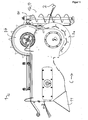
- the device 1 is suitable for removing parts of plants from any elongated, karstabilen, pliable growth aids, such as ropes or wires.
- the device 1 is suitable for use in viticulture to vine shoots, which are cut off from the vine, but still adhere to trained as Trellierdrähten growth aids 2 to remove.
- FIGS. 1 . 1a . 3 . 4a and 5 For better understanding in each case three growth aids 2 are shown.
- the device 1 comprises a growth aid guide 3 which is designed as an upwardly open guide channel with an approximately U-shaped cross-section perpendicular to the longitudinal axis of a growth aid 2 lying in the growth aid guide.
- the growth aid guide 3 By means of the growth aid guide 3, the growth aids 2 are guided in particular in the region of a detaching unit 4 of the device 1. This is especially true in the FIGS. 1a . 4a and 3 seen.
- the detaching unit 4 comprises a plurality of detachment elements, of which in FIG. 1a .
- FIG. 4a and 4b two detachment elements 4a and 4b are exemplified.
- the release elements are each designed as cutting blades, which are mounted on a common shaft 5 and can be set in rotation by means of a first motor 6.
- the device 1 further comprises a plant guide unit 7, which comprises a lower feed wheel 7a and an upper feed wheel 7b.
- the feed wheels 7a and 7b are driven in opposite directions by means of a second motor 8, according to the arrows in FIG FIG. 1 a.
- the device 1 To use the device 1, this is attached by means of a laterally arranged holder 9 on a (not shown) holding device, which holding device is in turn attached to a (not shown) tractor.
- the holding device By means of the holding device, the device 1 can be varied with respect to the height and with respect to the lateral orientation in the direction of travel right in front of the tractor.
- the device To use the device in a vineyard, such as Guyot or cordon training (these examples being non-limiting), either manually remove the respective trellis wires from the support posts along a line of grapevines or by means of appropriate holding devices, such as open-topped hooks Holding post be attached so that they can be pulled off to the top. At the first and last post of a grapevine line the trellis wires are permanently attached.
- the device is brought to a position near the first post and the upper Einzugsrad 7b and a top cover 10 (see FIGS. 4 and 6 ) are folded away by pivoting, so that the top view according to FIG. 4a results (with the folded-away elements are not shown) and the trellis wires 2 are placed from above on the lower feed wheel 7a and introduced into the growth aid guide 3 from above. Subsequently, upper cover 10 and upper feed wheel 7b are returned to the original position.
- the growth aids 2 thus run between upper feed wheel 7b and lower feed wheel 7a (see FIG. 3 ) and thus also through the growth aid guide 3 and thus likewise between the detachment elements of the detaching unit 4 (see FIGS. 2a and 2c) 4a ).
- the two detachment elements, between which the growth aid is guided preferably have a distance to one another in the axial direction in the range of 10 mm to 50 mm, preferably in the range of 20 mm to 40 mm, particularly preferably in the range of 25 mm to 35 mm, more preferably about 30 mm up. More preferably, the growth aid is guided approximately centrally between these two detachment elements.
- the two detachment elements 4, between which the growth aids 2 are guided approximately centrally have a distance from each other in the axial direction of 31 mm.
- the apparatus 1 is moved over the posts of the grapevine line by means of the tractor, so that the trellis wires 2 are pulled upwards out of the holders of the posts, unless they have already been removed from corresponding holders.
- the tractor is now moving along the vine line, so that the growth aids 2 are passed through the device 1 during this movement.
- the direction of movement of the device is indicated by an arrow C and the relative movement of the growth aids 2 to the device 1 by an arrow D, which relative movement is correspondingly opposite to the direction of movement C of the device 1.
- Plant parts adhering to the trellis wires, in particular vine shoots, are thus guided between the feed wheels 7a and 7b and optionally compressed by compression and supplied to the detaching unit 4 (together with the growth aid 2 moving relative to the device 1).
- the trained as a cutting blade, rotating detachment elements 4a, 4b solve the plant parts of the growth aids 2, by shredding, knocking and / or dismemberment.
- the growth aid guide 3 By means of the growth aid guide 3 it is ensured that the growth aids 2 do not come into contact with the detachment elements 4a, 4b of the detaching unit 4 and thus are not damaged by them and in particular are not severed.
- the release elements 4a, 4b rotate in the view in FIG. 1 a clockwise as indicated by arrow E. This means that, in particular above the shaft 5, the detachment elements 4a, 4b move in the opposite direction to the growth aid 2 and plant parts adhering to the growth aid. This ensures a particularly efficient detachment.
- the detached plant parts are at an outlet 11 (see FIGS. 1, 1 a and 2).
- the growth aids 2 are again secured in appropriate brackets to the posts of the grapevine line.
- the device 1 in addition to the lower feed wheel 7a designed as an upper feed wheel 7b counter element, ie a Schmidteinzugsrad, which are driven in opposite directions.
- the lateral surface 20 a plurality of pairs of recesses, of which in FIG. 7 for example, the pairs 21 ', 21 "and 21''' are marked.
- retraction elements 22 of which, for example, in FIG. 9 three feeder elements 22a, 22b and 22c are marked.
- the lateral surface 20 is octagonal in cross-section, wherein the eight thereby resulting sections of the lateral surface of the lower Einzugsrades 7a each have two recesses and thus each penetrated by a pair of intake elements 22.
- FIG. 9 is due to the central section in the sectional view only one feeder element 22 of the pairs of feeder elements to see.
- the catchment elements 22 are rotatable about a common axis of rotation (reference G in FIG FIG. 9 rotatably arranged.
- the rotation axis G is arranged parallel to the axis of rotation H of the lower feed wheel 7a and spaced therefrom. Due to the arrangement of the upper feed wheel 7b arranged approximately vertically above the axis of rotation H of the lower feed wheel 7a axis of rotation results in the FIG. 9 by "X" marked compression area, which essentially represents the area between the longitudinal extents of the two feed wheels.
- the axis of rotation G is spaced both in the direction of movement C of the device forward, as well as in a direction away from the compression region direction of the rotation axis H of the lower Einzugsrades 7a.
- catchment elements in a forward position with respect to the direction of movement of the device for example catchment element 22a in FIG. 9 further protrudes from the lateral surface 20 of the lower feed wheel 7a, as in a position to the rear, for example, when due to the rotation of the feed wheel 7a, the collection element 22a, the position of the feeder element 22c in FIG. 9 has reached.
- plant parts adhering to the growth aids 2 are thus additionally captured by the intake elements 22 and guided into the compression region between the two intake wheels 7a and 7b.
- the feeder elements already protrude less from the lateral surface 20 and in a position to the rear, for example, according to retraction element 22c in FIG. 9
- the feeder elements do not protrude or only slightly out of the lateral surface.
- the catchment elements thus release the plant parts in the rearward position, so that wrapping of the feed wheel 7a through the plant parts is avoided and, moreover, an action of the catchment elements on the growth aids 2 in this position is avoided.
- the pairwise arrangement of the intake elements 22 on the common axis of rotation next to each other is also in the sectional view according to FIG. 4b seen.
- the lower feed wheel 7a has an approximately trough-shaped cross-section parallel to the axis of rotation, wherein starting from a central position in the axial direction of the radius increases toward the outside.
- the feed wheel 7a has pull-in webs 23 extending parallel to the axis of rotation, which have a U-shaped region 23a for centrally guiding the growth aids in the axially central position and a plurality of serrated formations 23b for better collection of the plant parts.
- the collection elements 22 are elongated with rectangular cross section and have according to sectional view BB on the lying in the direction of rotation (top in FIG. 8 ) rounded edges. At the side facing away from the axis of rotation, the feeder elements 22 have a clearance angle ⁇ of 10 °, whereby the collection effect on the plant parts is increased.
- the feeder elements On the side facing the axis of rotation, the feeder elements have a C-profile for gripping around the sleeve surrounding the axis of rotation.
- the opening L of the C-profile is chosen such that it is smaller than the outer radius of the sleeve.
- the feed finger 22 can not be detached from the sleeve and thus not from the axis of rotation. If, however, the sleeve is displaced in the axial direction, so that the C-profile engages directly around the axis of rotation, the retraction element 22 can be removed, since the distance L is greater than the diameter of the axis of rotation.
- the pair of feed elements 22 with the shortest distance has a length of about 17 cm.
- the length of the intake elements 22 increases with increasing distance in the axial direction between the pairs up to a length of about 22 cm of the intake elements with the maximum distance in the axial direction.
- the plant guide unit 7 is due to the design with the lower feed wheel 7a and the upper feed wheel 7b, which have parallel axes of rotation, in particular for the entry of plant parts which extend approximately along the growth aids 2 and of plant parts, which in the front view according to FIG. 3 are approximately perpendicular, ie plant parts whose longitudinal extent, at least in projection on a plane perpendicular to the Growth aids 2 is approximately perpendicular to the axis of rotation of the lower feed wheel 7a and thus also perpendicular to the axis of rotation of the upper feed wheel 7b.
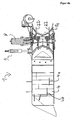
- the plant alignment unit 12 comprises a plant transport means 13 designed as a screw conveyor.
- the plant transport means 13 thus constitutes a linear conveying means.
- the plant alignment unit 12 further comprises a holder in which the plant transporting means 13 is rotatably mounted and a third motor 14 for rotating the screw conveyor of the plant transport means of the plant alignment unit 12 about the axis of the screw conveyor.
- the plant alignment unit 12 is arranged in front of the plant guide unit 7 with regard to the relative movement of the growth aid guide to the device. Plant parts adhering to the growth aids 2 thus reach first into the area of action of the plant alignment unit 12 and then into the area of action of the plant guidance unit 7.
- Plant parts which project laterally from the growth aids 2 can thus be grasped and moved by the plant transport means 13.
- the direction of rotation is chosen such that the detected by the plant transport means 13. Plant parts in FIG. 3 to be moved upwards.
- FIG. 3 Exemplary is in FIG. 3 as a dotted line a plant part F shown schematically, which is approximately perpendicular to the growth aids 2 and horizontally as shown in FIG FIG. 3 projects.
- the plant part F is detected by the plant transport means 13 and with its in FIG. 3 moved right end up, so that the plant part F rotation about the growth aids 2 in the counterclockwise direction in the illustration FIG. 3 performs.
- the plant part F is further approximated the plant guide unit 7, but applies to this in a vertical or nearly vertical orientation as shown in FIG. 3 and can thus be fed easily with the plant guide unit 7.
- Trained as a screw conveyor plant transport means 13 has in the axial extent a length of about 60 cm with a screw pitch of about 12.5 cm and a diameter of about 12.5 cm.
- the diameter of the screw decreases continuously toward the respective end of the axis of the screw.
- the part of the transporting means 13 designed as a screw conveyor is operated by means of the third motor 14 at a rotational speed of about 220 rpm.
- the plant guide unit 7 is due to the design with the lower feed wheel 7a and the upper feed wheel 7b, which have parallel axes of rotation, in particular for the entry of plant parts which extend approximately along the growth aids 2 and of plant parts, which in the front view according to FIG. 3 are approximately perpendicular, ie plant parts whose longitudinal extent is at least in projection on a plane perpendicular to the growth aids 2 approximately perpendicular to the axis of rotation of the lower feed wheel 7a and thus also perpendicular to the axis of rotation of the upper feed wheel 7b.
- the plant alignment unit 12 comprises a plant transport means 13 designed as a screw conveyor.
- the plant transport means 13 thus constitutes a linear conveying means.
- the plant alignment unit 12 further comprises a holder in which the plant transporting means 13 is rotatably mounted and a third motor 14 for rotating the screw conveyor of the plant transport means of the plant alignment unit 12 about the axis of the screw conveyor.
- the plant alignment unit 12 is arranged in front of the plant guide unit 7 with regard to the relative movement of the growth aid guide to the device. Plant parts adhering to the growth aids 2 thus reach first into the area of action of the plant alignment unit 12 and then into the area of action of the plant guidance unit 7.
- Plant parts which project laterally from the growth aids 2 can thus be grasped and moved by the plant transport means 13.
- the direction of rotation is chosen such that the plant parts detected by the plant transport means 13 in FIG. 3 to be moved upwards.
- FIG. 3 Exemplary is in FIG. 3 as a dotted line a plant part F shown schematically, which is approximately perpendicular to the growth aids 2 and horizontally as shown in FIG FIG. 3 projects.
- the plant part F is detected by the plant transport means 13 and with its in FIG. 3 moved right end up, so that the plant part F rotation about the growth aids 2 in the counterclockwise direction in the illustration FIG. 3 performs.
- the plant part F is further approximated the plant guide unit 7, but applies to this in a vertical or nearly vertical orientation as shown in FIG. 3 and can thus be fed easily with the plant guide unit 7.
- Trained as a screw conveyor plant transport means 13 has in the axial extent a length of about 60 cm with a screw pitch of about 12.5 cm and a diameter of about 12.5 cm.
- the diameter of the screw decreases continuously toward the respective end of the axis of the screw.
- the part of the transporting means 13 designed as a screw conveyor is operated by means of the third motor 14 at a rotational speed of about 220 rpm.
Landscapes
- Life Sciences & Earth Sciences (AREA)
- Environmental Sciences (AREA)
- Biodiversity & Conservation Biology (AREA)
- Ecology (AREA)
- Forests & Forestry (AREA)
- Botany (AREA)
- Cultivation Of Plants (AREA)
Claims (15)
- Dispositif (1) pour supprimer des éléments de plantes d'au moins une aide à la croissance (2) oblongue, stable en traction et molle en flexion, pendant un déplacement du dispositif (1) le long de l'aide à la croissance (2), en particulier pour supprimer des rejets de vigne d'au moins un fil métallique d'espalier,
comprenant- un guide (3) d'aide à la croissance, pour guider l'aide à la croissance (2) pendant le déplacement du dispositif (1) le long de l'aide à la croissance (2),- une unité de détachement (4) et- une unité (7) de guidage de plantes pour comprimer et/ou apporter à l'unité de détachement (4) les éléments de plantes adhérant à l'aide à la croissance (2),ladite unité de détachement (4) comprenant au moins un élément de détachement qui est disposé à déplacement sur le dispositif (1) de telle sorte qu'en service, par le déplacement de l'élément de détachement, des éléments de plantes peuvent être au moins partiellement détachés de l'aide à la croissance (2),
et ladite unité (7) de guidage de plantes comprenant au moins une roue d'engagement disposée à rotation, pour engager et/ou comprimer les éléments de plantes,
caractérisé en ce que l'unité (7) de guidage de plantes comprend une pluralité d'éléments d'engagement (22a, 22b, 22c),
sachant que chaque élément de la pluralité d'éléments d'engagement (22a, 22b, 22c) est disposé à déplacement et en traversant une surface périphérique réelle ou imaginaire de la roue d'engagement, de telle sorte que, lors d'une rotation de la roue d'engagement, l'élément d'engagement dépasse plus de la surface périphérique dans une position vers l'avant, par rapport à la direction de déplacement du dispositif (1), que dans une position vers l'arrière. - Dispositif (1) selon la revendication 1, caractérisé en ce que chaque élément de la pluralité d'éléments d'engagement (22a, 22b, 22c) est disposé à rotation avec un axe de rotation perpendiculaire à une étendue longitudinale de l'élément d'engagement,
en ce que, de préférence, tous les éléments d'engagement sont disposés à rotation autour d'un axe de rotation commun,
en ce que, d'une manière encore plus préférée, les éléments de la pluralité d'éléments d'engagement (22a, 22b, 22c) sont décalés dans la direction axiale de leur axe de rotation commun, de préférence sont disposés les uns à côté des autres. - Dispositif (1) selon la revendication 2, caractérisé en ce que l'axe de rotation de chaque élément de la pluralité d'éléments d'engagement (22a, 22b, 22c) est parallèle à l'axe de rotation de la roue d'engagement,
en ce que, de préférence, l'axe de rotation de chaque élément de la pluralité d'éléments d'engagement (22a, 22b, 22c) est disposé à distance de l'axe de rotation de la roue d'engagement au moins vers l'avant dans la direction de déplacement du dispositif (1), et/ou en ce que l'axe de rotation de chaque élément de la pluralité d'éléments d'engagement (22a, 22b, 22c) est disposé à distance de l'axe de rotation de la roue d'engagement au moins dans une direction éloignée d'une zone de compression de la roue d'engagement. - Dispositif (1) selon l'une des revendications précédentes, caractérisé en ce que les éléments d'engagement sont disposés par groupes dans la direction axiale de leur axe de rotation, de préférence par paires.
- Dispositif (1) selon la revendication 4, caractérisé en ce que les groupes présentent des distances différentes en direction axiale entre les éléments d'engagement (22a, 22b, 22c),
en ce que, de préférence, dans la direction de rotation de la roue d'engagement, les groupes présentent une distance croissante entre les éléments d'engagement en direction axiale. - Dispositif (1) selon l'une des revendications précédentes, caractérisé en ce que l'unité (7) de guidage de plantes présente un pendant à la roue d'engagement, qui est disposé afin de former entre la roue d'engagement et le pendant une zone de compression pour les éléments de plantes,
en ce que, de préférence, le pendant est réalisé sous forme de roue d'engagement antagoniste. - Dispositif (1) selon la revendication 6, caractérisé en ce que les éléments d'engagement présentent, dans la zone de compression, une distance par rapport au pendant dans la plage de 1 cm à 20 cm, de préférence dans la plage de 1 cm à 10 cm, d'une manière encore plus préférée dans la plage de 1 cm à 5 cm.
- Dispositif (1) selon la revendication 5 et selon l'une des revendications 6 à 7, caractérisé en ce que le pendant est réalisé sous forme de roue d'engagement antagoniste avec un rayon diminuant vers l'extérieur en direction axiale, et les éléments d'engagement plus distants en direction axiale présentent une plus grande longueur que les éléments d'engagement moins distants.
- Dispositif (1) selon l'une des revendications précédentes, caractérisé en ce que les éléments de la pluralité d'éléments d'engagement (22a, 22b, 22c), à l'extrémité de la zone de compression située à l'opposé de la direction de déplacement du dispositif (1), dépassent de la surface périphérique (20) de la roue d'engagement de moins de 5 cm, de préférence de moins de 3 cm, d'une manière encore plus préférée n'en dépassent pas.
- Dispositif (1) selon l'une des revendications précédentes, caractérisé en ce que la roue d'engagement présente un guide approximativement central en direction axiale pour une aide à la croissance (2),
en ce que, de préférence, la roue d'engagement est réalisée avec une section approximativement en forme de cuvette parallèlement à l'axe de rotation, de préférence présente en direction axiale un rayon augmentant vers l'extérieur. - Dispositif (1) selon l'une des revendications précédentes, caractérisé en ce que la roue d'engagement présente une surface périphérique (20) avec des évidements (21', 21", 21"') et/ou des guides pour les éléments d'engagement.
- Dispositif (1) selon l'une des revendications précédentes, caractérisé en ce que chaque élément de la pluralité d'éléments d'engagement (22a, 22b, 22c) est disposé de manière amovible sur un axe de rotation, de préférence est disposé de manière amovible et rotative sur un axe de rotation.
- Dispositif (1) selon la revendication 12, caractérisé en ce qu'une ou plusieurs douilles sélectivement coulissantes en direction axiale sont disposées autour de l'axe de rotation,
en ce que chaque élément de la pluralité d'éléments d'engagement (22a, 22b, 22c) s'engage partiellement autour d'au moins une douille, de préférence en ce qu'un profil en C est formé sur chaque élément de la pluralité d'éléments d'engagement (22a, 22b, 22c) pour s'engager autour de la douille. - Dispositif (1) selon l'une des revendications précédentes, caractérisé en ce que chaque élément de la pluralité d'éléments d'engagement (22a, 22b, 22c) présente des bords arrondis sur le côté dirigé dans la direction de rotation,
en ce que, de préférence, chaque élément de la pluralité d'éléments d'engagement (22a, 22b, 22c) présente perpendiculairement à l'étendue longitudinale une section approximativement rectangulaire avec des bords arrondis sur le côté dirigé dans la direction de rotation. - Dispositif (1) selon l'une des revendications précédentes, caractérisé en ce que chaque élément de la pluralité d'éléments d'engagement (22a, 22b, 22c) présente un angle de dépouille à l'extrémité dépassant de la surface périphérique (20), de préférence un angle de dépouille dans la plage de 2° à 30°, d'une manière encore plus préférée dans la plage de 5° à 15°, en particulier d'environ 10°.
Priority Applications (1)
| Application Number | Priority Date | Filing Date | Title |
|---|---|---|---|
| EP11001169.9A EP2486787B1 (fr) | 2011-02-14 | 2011-02-14 | Dispositif destiné à supprimer des éléments de plantes d'une aide à la croissance |
Applications Claiming Priority (1)
| Application Number | Priority Date | Filing Date | Title |
|---|---|---|---|
| EP11001169.9A EP2486787B1 (fr) | 2011-02-14 | 2011-02-14 | Dispositif destiné à supprimer des éléments de plantes d'une aide à la croissance |
Publications (2)
| Publication Number | Publication Date |
|---|---|
| EP2486787A1 EP2486787A1 (fr) | 2012-08-15 |
| EP2486787B1 true EP2486787B1 (fr) | 2013-04-24 |
Family
ID=44358073
Family Applications (1)
| Application Number | Title | Priority Date | Filing Date |
|---|---|---|---|
| EP11001169.9A Active EP2486787B1 (fr) | 2011-02-14 | 2011-02-14 | Dispositif destiné à supprimer des éléments de plantes d'une aide à la croissance |
Country Status (1)
| Country | Link |
|---|---|
| EP (1) | EP2486787B1 (fr) |
Cited By (2)
| Publication number | Priority date | Publication date | Assignee | Title |
|---|---|---|---|---|
| DE102013219651B3 (de) * | 2013-09-27 | 2014-11-20 | ERO-Gerätebau GmbH | Vorrichtung zum Entfernen von Pflanzenteilen von einer Wuchshilfe |
| EP2823704A2 (fr) | 2013-07-11 | 2015-01-14 | ERO-GERÄTEBAU GmbH | Dispositif et procédé destinés à enlever des parties de plantes |
Families Citing this family (1)
| Publication number | Priority date | Publication date | Assignee | Title |
|---|---|---|---|---|
| FR2976447B1 (fr) * | 2011-06-20 | 2013-07-12 | Jean-Yves Deze | Machine a tirer automatiquement les sarments de vigne tailles |
Family Cites Families (3)
| Publication number | Priority date | Publication date | Assignee | Title |
|---|---|---|---|---|
| FR2746581B1 (fr) * | 1996-04-01 | 1998-05-22 | Fontan Gerard | Tailleuse elevatrice separatrice |
| DE102004031088B4 (de) | 2004-06-28 | 2007-09-27 | Manfred Bermes | Verfahren zum Entfernen von Zweigen aus einem Spalier und Vorrichtung dazu |
| EP2197264B1 (fr) | 2007-10-19 | 2018-05-09 | Honeypot Holdings Limited | Procédé et appareil d'extraction de matériau d'un fil |
-
2011
- 2011-02-14 EP EP11001169.9A patent/EP2486787B1/fr active Active
Cited By (4)
| Publication number | Priority date | Publication date | Assignee | Title |
|---|---|---|---|---|
| EP2823704A2 (fr) | 2013-07-11 | 2015-01-14 | ERO-GERÄTEBAU GmbH | Dispositif et procédé destinés à enlever des parties de plantes |
| DE102013213623A1 (de) | 2013-07-11 | 2015-01-15 | ERO-Gerätebau GmbH | Vorrichtung und Verfahren zum Entfernen von Pflanzenteilen |
| DE102013219651B3 (de) * | 2013-09-27 | 2014-11-20 | ERO-Gerätebau GmbH | Vorrichtung zum Entfernen von Pflanzenteilen von einer Wuchshilfe |
| EP2853149A1 (fr) | 2013-09-27 | 2015-04-01 | ERO-GERÄTEBAU GmbH | Dispositif de tirage de sarments de vignes |
Also Published As
| Publication number | Publication date |
|---|---|
| EP2486787A1 (fr) | 2012-08-15 |
Similar Documents
| Publication | Publication Date | Title |
|---|---|---|
| WO1997017751A1 (fr) | Dispositif de denudage | |
| CH716237B1 (de) | Vorrichtung zur Bündelung von Blattgemüse. | |
| EP2486787B1 (fr) | Dispositif destiné à supprimer des éléments de plantes d'une aide à la croissance | |
| EP2649882B1 (fr) | Dispositif de séparation et de mise en forme de pâte | |
| EP2266384B1 (fr) | Dispositif de sarclage pour plantes aquatiques et bateau de sarclage doté d'un tel dispositif | |
| EP2853149B1 (fr) | Dispositif de tirage de sarments de vignes | |
| EP2823704B1 (fr) | Dispositif et procédé destinés à enlever des parties de plantes | |
| DD213583B5 (de) | Silagegutschneider | |
| EP2486786A1 (fr) | Procédé et dispositif destinés à supprimer des éléments de plantes d'un fil de support | |
| EP3007540B1 (fr) | Dispositif à cueillir | |
| DE102006044920A1 (de) | Nachpflückeinrichtung für eine Hopfenpflückmaschine | |
| EP2486788A1 (fr) | Dispositif destiné à supprimer des éléments de plantes d'une aide à la croissance | |
| EP2486789A1 (fr) | Dispositif destiné à supprimer des éléments de plantes d'une aide à la croissance | |
| DE102020116575B4 (de) | Vorrichtung und Verfahren zur zumindest seitlichen Zuschneidung eines Kartonrohlings | |
| DE2608160C3 (de) | Vorrichtung zum Auslösen abgelängter Drähte aus einem ungeordneten Drahtbündel, insbesondere beim Zuführen der Drähte zu einer Verarbeitungsmaschine | |
| EP2457443B1 (fr) | Procédé de torsion mécanique de bandes de pâte | |
| EP2884833B1 (fr) | Dispositif et procédé pour éliminer des rameaux, notamment des sarments, d'un espalier | |
| EP3651563B1 (fr) | Dispositif permettant d'empêcher toute accumulation de fanes et machine de récolte associée | |
| DE102007010550A1 (de) | Vorrichtung und Verfahren zum Schälen von länglichem Gemüse | |
| DE102007049344B4 (de) | Vorrichtung zur Entlaubung, insbesondere von Weinstöcken | |
| AT505654B1 (de) | Verfahren und vorrichtung zum ausgeizen von geiztrieben | |
| DE8217281U1 (de) | Rübenblatterntevorrichtung an einer Rübenerntemaschine | |
| AT248775B (de) | Erntemaschine für Mohnköpfe | |
| WO2014198599A1 (fr) | Moissonneuse pour moissonner des plantes a tiges | |
| DE102011106181A1 (de) | Fahrbare Vorrichtung zum Ausziehen von Ruten, Zweigen, Trieben, insbesondere von Reben, aus einem Spalier |
Legal Events
| Date | Code | Title | Description |
|---|---|---|---|
| PUAI | Public reference made under article 153(3) epc to a published international application that has entered the european phase |
Free format text: ORIGINAL CODE: 0009012 |
|
| 17P | Request for examination filed |
Effective date: 20120301 |
|
| AK | Designated contracting states |
Kind code of ref document: A1 Designated state(s): AL AT BE BG CH CY CZ DE DK EE ES FI FR GB GR HR HU IE IS IT LI LT LU LV MC MK MT NL NO PL PT RO RS SE SI SK SM TR |
|
| AX | Request for extension of the european patent |
Extension state: BA ME |
|
| GRAP | Despatch of communication of intention to grant a patent |
Free format text: ORIGINAL CODE: EPIDOSNIGR1 |
|
| RAP1 | Party data changed (applicant data changed or rights of an application transferred) |
Owner name: ERO-GERAETEBAU GMBH |
|
| GRAS | Grant fee paid |
Free format text: ORIGINAL CODE: EPIDOSNIGR3 |
|
| GRAA | (expected) grant |
Free format text: ORIGINAL CODE: 0009210 |
|
| AK | Designated contracting states |
Kind code of ref document: B1 Designated state(s): AL AT BE BG CH CY CZ DE DK EE ES FI FR GB GR HR HU IE IS IT LI LT LU LV MC MK MT NL NO PL PT RO RS SE SI SK SM TR |
|
| REG | Reference to a national code |
Ref country code: GB Ref legal event code: FG4D Free format text: NOT ENGLISH |
|
| REG | Reference to a national code |
Ref country code: CH Ref legal event code: EP |
|
| REG | Reference to a national code |
Ref country code: AT Ref legal event code: REF Ref document number: 607991 Country of ref document: AT Kind code of ref document: T Effective date: 20130515 |
|
| REG | Reference to a national code |
Ref country code: IE Ref legal event code: FG4D Free format text: LANGUAGE OF EP DOCUMENT: GERMAN |
|
| REG | Reference to a national code |
Ref country code: DE Ref legal event code: R096 Ref document number: 502011000636 Country of ref document: DE Effective date: 20130620 |
|
| REG | Reference to a national code |
Ref country code: LT Ref legal event code: MG4D |
|
| REG | Reference to a national code |
Ref country code: NL Ref legal event code: VDEP Effective date: 20130424 |
|
| PG25 | Lapsed in a contracting state [announced via postgrant information from national office to epo] |
Ref country code: PT Free format text: LAPSE BECAUSE OF FAILURE TO SUBMIT A TRANSLATION OF THE DESCRIPTION OR TO PAY THE FEE WITHIN THE PRESCRIBED TIME-LIMIT Effective date: 20130826 Ref country code: GR Free format text: LAPSE BECAUSE OF FAILURE TO SUBMIT A TRANSLATION OF THE DESCRIPTION OR TO PAY THE FEE WITHIN THE PRESCRIBED TIME-LIMIT Effective date: 20130725 Ref country code: ES Free format text: LAPSE BECAUSE OF FAILURE TO SUBMIT A TRANSLATION OF THE DESCRIPTION OR TO PAY THE FEE WITHIN THE PRESCRIBED TIME-LIMIT Effective date: 20130804 Ref country code: IS Free format text: LAPSE BECAUSE OF FAILURE TO SUBMIT A TRANSLATION OF THE DESCRIPTION OR TO PAY THE FEE WITHIN THE PRESCRIBED TIME-LIMIT Effective date: 20130824 Ref country code: SI Free format text: LAPSE BECAUSE OF FAILURE TO SUBMIT A TRANSLATION OF THE DESCRIPTION OR TO PAY THE FEE WITHIN THE PRESCRIBED TIME-LIMIT Effective date: 20130424 Ref country code: SE Free format text: LAPSE BECAUSE OF FAILURE TO SUBMIT A TRANSLATION OF THE DESCRIPTION OR TO PAY THE FEE WITHIN THE PRESCRIBED TIME-LIMIT Effective date: 20130424 Ref country code: LT Free format text: LAPSE BECAUSE OF FAILURE TO SUBMIT A TRANSLATION OF THE DESCRIPTION OR TO PAY THE FEE WITHIN THE PRESCRIBED TIME-LIMIT Effective date: 20130424 Ref country code: NO Free format text: LAPSE BECAUSE OF FAILURE TO SUBMIT A TRANSLATION OF THE DESCRIPTION OR TO PAY THE FEE WITHIN THE PRESCRIBED TIME-LIMIT Effective date: 20130724 Ref country code: FI Free format text: LAPSE BECAUSE OF FAILURE TO SUBMIT A TRANSLATION OF THE DESCRIPTION OR TO PAY THE FEE WITHIN THE PRESCRIBED TIME-LIMIT Effective date: 20130424 |
|
| PG25 | Lapsed in a contracting state [announced via postgrant information from national office to epo] |
Ref country code: BG Free format text: LAPSE BECAUSE OF FAILURE TO SUBMIT A TRANSLATION OF THE DESCRIPTION OR TO PAY THE FEE WITHIN THE PRESCRIBED TIME-LIMIT Effective date: 20130724 Ref country code: PL Free format text: LAPSE BECAUSE OF FAILURE TO SUBMIT A TRANSLATION OF THE DESCRIPTION OR TO PAY THE FEE WITHIN THE PRESCRIBED TIME-LIMIT Effective date: 20130424 Ref country code: CY Free format text: LAPSE BECAUSE OF FAILURE TO SUBMIT A TRANSLATION OF THE DESCRIPTION OR TO PAY THE FEE WITHIN THE PRESCRIBED TIME-LIMIT Effective date: 20130424 Ref country code: HR Free format text: LAPSE BECAUSE OF FAILURE TO SUBMIT A TRANSLATION OF THE DESCRIPTION OR TO PAY THE FEE WITHIN THE PRESCRIBED TIME-LIMIT Effective date: 20130424 Ref country code: RS Free format text: LAPSE BECAUSE OF FAILURE TO SUBMIT A TRANSLATION OF THE DESCRIPTION OR TO PAY THE FEE WITHIN THE PRESCRIBED TIME-LIMIT Effective date: 20130424 Ref country code: LV Free format text: LAPSE BECAUSE OF FAILURE TO SUBMIT A TRANSLATION OF THE DESCRIPTION OR TO PAY THE FEE WITHIN THE PRESCRIBED TIME-LIMIT Effective date: 20130424 |
|
| PG25 | Lapsed in a contracting state [announced via postgrant information from national office to epo] |
Ref country code: CZ Free format text: LAPSE BECAUSE OF FAILURE TO SUBMIT A TRANSLATION OF THE DESCRIPTION OR TO PAY THE FEE WITHIN THE PRESCRIBED TIME-LIMIT Effective date: 20130424 Ref country code: EE Free format text: LAPSE BECAUSE OF FAILURE TO SUBMIT A TRANSLATION OF THE DESCRIPTION OR TO PAY THE FEE WITHIN THE PRESCRIBED TIME-LIMIT Effective date: 20130424 Ref country code: DK Free format text: LAPSE BECAUSE OF FAILURE TO SUBMIT A TRANSLATION OF THE DESCRIPTION OR TO PAY THE FEE WITHIN THE PRESCRIBED TIME-LIMIT Effective date: 20130424 Ref country code: SK Free format text: LAPSE BECAUSE OF FAILURE TO SUBMIT A TRANSLATION OF THE DESCRIPTION OR TO PAY THE FEE WITHIN THE PRESCRIBED TIME-LIMIT Effective date: 20130424 |
|
| PG25 | Lapsed in a contracting state [announced via postgrant information from national office to epo] |
Ref country code: NL Free format text: LAPSE BECAUSE OF FAILURE TO SUBMIT A TRANSLATION OF THE DESCRIPTION OR TO PAY THE FEE WITHIN THE PRESCRIBED TIME-LIMIT Effective date: 20130424 Ref country code: RO Free format text: LAPSE BECAUSE OF FAILURE TO SUBMIT A TRANSLATION OF THE DESCRIPTION OR TO PAY THE FEE WITHIN THE PRESCRIBED TIME-LIMIT Effective date: 20130424 |
|
| PLBE | No opposition filed within time limit |
Free format text: ORIGINAL CODE: 0009261 |
|
| STAA | Information on the status of an ep patent application or granted ep patent |
Free format text: STATUS: NO OPPOSITION FILED WITHIN TIME LIMIT |
|
| 26N | No opposition filed |
Effective date: 20140127 |
|
| REG | Reference to a national code |
Ref country code: DE Ref legal event code: R097 Ref document number: 502011000636 Country of ref document: DE Effective date: 20140127 |
|
| BERE | Be: lapsed |
Owner name: ERO-GERATEBAU G.M.B.H. Effective date: 20140228 |
|
| PG25 | Lapsed in a contracting state [announced via postgrant information from national office to epo] |
Ref country code: LU Free format text: LAPSE BECAUSE OF FAILURE TO SUBMIT A TRANSLATION OF THE DESCRIPTION OR TO PAY THE FEE WITHIN THE PRESCRIBED TIME-LIMIT Effective date: 20140214 Ref country code: MC Free format text: LAPSE BECAUSE OF FAILURE TO SUBMIT A TRANSLATION OF THE DESCRIPTION OR TO PAY THE FEE WITHIN THE PRESCRIBED TIME-LIMIT Effective date: 20130424 |
|
| REG | Reference to a national code |
Ref country code: CH Ref legal event code: PL |
|
| PG25 | Lapsed in a contracting state [announced via postgrant information from national office to epo] |
Ref country code: CH Free format text: LAPSE BECAUSE OF NON-PAYMENT OF DUE FEES Effective date: 20140228 Ref country code: LI Free format text: LAPSE BECAUSE OF NON-PAYMENT OF DUE FEES Effective date: 20140228 |
|
| REG | Reference to a national code |
Ref country code: IE Ref legal event code: MM4A |
|
| PG25 | Lapsed in a contracting state [announced via postgrant information from national office to epo] |
Ref country code: BE Free format text: LAPSE BECAUSE OF NON-PAYMENT OF DUE FEES Effective date: 20140228 Ref country code: IE Free format text: LAPSE BECAUSE OF NON-PAYMENT OF DUE FEES Effective date: 20140214 |
|
| GBPC | Gb: european patent ceased through non-payment of renewal fee |
Effective date: 20150214 |
|
| PG25 | Lapsed in a contracting state [announced via postgrant information from national office to epo] |
Ref country code: GB Free format text: LAPSE BECAUSE OF NON-PAYMENT OF DUE FEES Effective date: 20150214 |
|
| REG | Reference to a national code |
Ref country code: FR Ref legal event code: PLFP Year of fee payment: 6 |
|
| PG25 | Lapsed in a contracting state [announced via postgrant information from national office to epo] |
Ref country code: MT Free format text: LAPSE BECAUSE OF FAILURE TO SUBMIT A TRANSLATION OF THE DESCRIPTION OR TO PAY THE FEE WITHIN THE PRESCRIBED TIME-LIMIT Effective date: 20130424 |
|
| PG25 | Lapsed in a contracting state [announced via postgrant information from national office to epo] |
Ref country code: SM Free format text: LAPSE BECAUSE OF FAILURE TO SUBMIT A TRANSLATION OF THE DESCRIPTION OR TO PAY THE FEE WITHIN THE PRESCRIBED TIME-LIMIT Effective date: 20130424 |
|
| PG25 | Lapsed in a contracting state [announced via postgrant information from national office to epo] |
Ref country code: HU Free format text: LAPSE BECAUSE OF FAILURE TO SUBMIT A TRANSLATION OF THE DESCRIPTION OR TO PAY THE FEE WITHIN THE PRESCRIBED TIME-LIMIT; INVALID AB INITIO Effective date: 20110214 Ref country code: TR Free format text: LAPSE BECAUSE OF FAILURE TO SUBMIT A TRANSLATION OF THE DESCRIPTION OR TO PAY THE FEE WITHIN THE PRESCRIBED TIME-LIMIT Effective date: 20130424 |
|
| REG | Reference to a national code |
Ref country code: FR Ref legal event code: PLFP Year of fee payment: 7 |
|
| REG | Reference to a national code |
Ref country code: FR Ref legal event code: PLFP Year of fee payment: 8 |
|
| PG25 | Lapsed in a contracting state [announced via postgrant information from national office to epo] |
Ref country code: MK Free format text: LAPSE BECAUSE OF FAILURE TO SUBMIT A TRANSLATION OF THE DESCRIPTION OR TO PAY THE FEE WITHIN THE PRESCRIBED TIME-LIMIT Effective date: 20130424 |
|
| PG25 | Lapsed in a contracting state [announced via postgrant information from national office to epo] |
Ref country code: AL Free format text: LAPSE BECAUSE OF FAILURE TO SUBMIT A TRANSLATION OF THE DESCRIPTION OR TO PAY THE FEE WITHIN THE PRESCRIBED TIME-LIMIT Effective date: 20130424 |
|
| PGFP | Annual fee paid to national office [announced via postgrant information from national office to epo] |
Ref country code: FR Payment date: 20230217 Year of fee payment: 13 |
|
| PGFP | Annual fee paid to national office [announced via postgrant information from national office to epo] |
Ref country code: IT Payment date: 20230228 Year of fee payment: 13 |
|
| P01 | Opt-out of the competence of the unified patent court (upc) registered |
Effective date: 20230515 |
|
| PGFP | Annual fee paid to national office [announced via postgrant information from national office to epo] |
Ref country code: AT Payment date: 20240216 Year of fee payment: 14 |
|
| PGFP | Annual fee paid to national office [announced via postgrant information from national office to epo] |
Ref country code: DE Payment date: 20240117 Year of fee payment: 14 |