EP2486788A1 - Dispositif destiné à supprimer des éléments de plantes d'une aide à la croissance - Google Patents
Dispositif destiné à supprimer des éléments de plantes d'une aide à la croissance Download PDFInfo
- Publication number
- EP2486788A1 EP2486788A1 EP11001170A EP11001170A EP2486788A1 EP 2486788 A1 EP2486788 A1 EP 2486788A1 EP 11001170 A EP11001170 A EP 11001170A EP 11001170 A EP11001170 A EP 11001170A EP 2486788 A1 EP2486788 A1 EP 2486788A1
- Authority
- EP
- European Patent Office
- Prior art keywords
- rotation
- growth aid
- plant
- axis
- growth
- Prior art date
- Legal status (The legal status is an assumption and is not a legal conclusion. Google has not performed a legal analysis and makes no representation as to the accuracy of the status listed.)
- Withdrawn
Links
Images


Classifications
-
- A—HUMAN NECESSITIES
- A01—AGRICULTURE; FORESTRY; ANIMAL HUSBANDRY; HUNTING; TRAPPING; FISHING
- A01G—HORTICULTURE; CULTIVATION OF VEGETABLES, FLOWERS, RICE, FRUIT, VINES, HOPS OR SEAWEED; FORESTRY; WATERING
- A01G17/00—Cultivation of hops, vines, fruit trees, or like trees
- A01G17/02—Cultivation of hops or vines
-
- A—HUMAN NECESSITIES
- A01—AGRICULTURE; FORESTRY; ANIMAL HUSBANDRY; HUNTING; TRAPPING; FISHING
- A01G—HORTICULTURE; CULTIVATION OF VEGETABLES, FLOWERS, RICE, FRUIT, VINES, HOPS OR SEAWEED; FORESTRY; WATERING
- A01G3/00—Cutting implements specially adapted for horticultural purposes; Delimbing standing trees
- A01G3/04—Apparatus for trimming hedges, e.g. hedge shears
- A01G3/0408—Apparatus for trimming hedges, e.g. hedge shears specially adapted for trellis work, e.g. machines for pruning vine or the like
Definitions
- the invention relates to a device for removing parts of plants from at least one elongated, karstabilen, limp growth aid during movement of the device along the growth aid according to the preamble of claim 1.
- pliable growth aids such as ropes or wires are known to support the plants and / or to influence the growth of the plants.
- pliable growth aids such as ropes or wires
- the use of trellis wires is known, for example in Guyot and also in cordon education.
- WO 2009/051498 A2 an apparatus and a method for removing parts of plants from a growth aid is known, wherein adhering to the growth aid plant parts are compressed by means of a plant supply unit and / or supplied to a detaching unit.
- the detaching unit comprises at least one detaching element, such as a rotating cutting blade, by means of which the plant parts are at least partially detached from the growth aid.
- the growth aid is guided during the machining process by means of a growth aid guide in order to avoid in particular damage to the growth aid guide by the detachment element.
- the present invention is therefore based on the object to improve the prior art devices for removing parts of plants from a growth aid and to reduce the susceptibility to errors and resulting interruptions during operation, in particular the risk of damage and / or severing the growth aid by the detachment element to reduce.
- the device according to the invention for removing parts of plants from at least one elongated, tensile stable, non-limp growth aid during a movement of the device along the growth aid comprises a growth aid guide for guiding the growth aid during the movement of the device along the growth aid. Furthermore, the device comprises a detachment unit. The apparatus further comprises a plant guide unit for compressing and / or feeding the plant parts adhering to the growth aid to the detachment unit.
- the detachment unit comprises at least one detachment element, which detachment element is movably arranged on the device in such a way that, when operated by movement of the detachment element, plant parts are at least partially detachable from the growth aid.
- the detaching element is designed as a cutting blade and arranged by means of a motor drive about a rotation axis rotatably mounted on the detaching unit.
- the release element at least on the edges pointing in operation in the direction of rotation, at least in some areas has a bevel on the side facing away from the growth aid during operation and no beveled on the side facing the growth aid during operation.
- Typical cutting blades have a two-sided bevel on the cutting edge, as this improves the cutting action in many situations.
- the present invention is based on the Applicant's finding that the necessary cutting force for operating the detachment element is less due to the one-sided bevel.
- the risk of "catching" the growth aid by the release element, ie to damage and / or separate and / or wound further reduced if no bevel on the side facing in operation in the direction of rotation edge of the detachment element on the side facing the operation of the growth aid is present.
- This will be a repellent effect achieved for the growth aid, especially for trellis wires, compared with cutting blades, which have a two-sided bevel or arranged only in the direction of growth aid bevel.
- the present invention leads to the surprising effects that a lower motor drive power is necessary to operate the detachment unit and the risk of damaging the growth aid is reduced.
- the release element preferably has a bevel angle in the range of 20 ° to 45 °, more preferably in the range of 25 ° to 35 °, in particular of approximately 30 °. This achieves an optimization between reduction of the necessary drive power of the detachment unit, sufficient stability and durability of the detachment element and a sufficiently high cutting action.
- the release element has no beveled on the edges pointing in operation against the direction of rotation.
- the stability and durability of the detachment element is increased and, on the other hand, the risk is considerably reduced that contact of the growth aid with the edges which, when operating against the direction of rotation, damage the Growth help occurs.
- the operation of the growth aid facing side of the release element is flat, more preferably formed perpendicular to the axis of rotation of the release element standing.
- the curved course with a curvature (or approximate curvature) formed counter to the direction of rotation has the effect that in the case of contact of the curved edge with the growth aid the growth aid is acted upon by the curvature with a smaller tangential force in the direction of rotation and due to the curvature additionally Force component occurs in the radial outward direction, which thus guides the growth aid away from the release element.
- This achieves an additional reduction in the risk of damage to the growth aid.
- the cutting action is improved: Due to the course described results in a "pulling cut” and thus a smoother cut on the plant parts compared with cutting blades without such curvature. Furthermore, the necessary cutting force is reduced, i. the necessary motor drive power for the detachment unit is further reduced.
- the segmentation has at least three segments, preferably at least five segments, in order to approximate the curvature.
- the edges which have a bevelled edge when operating in the direction of rotation, to have a curved course with optionally varying radii of curvature in a plane perpendicular to the axis of rotation of the detaching element.
- the arcuate course leads to a particularly efficient sliding of the growth aid in the radial direction to the outside upon contact with the release element.
- the radii of the arc are in the range 2 cm to 40 cm, preferably in the range 5 cm to 30 cm.
- the arcuate profile has at least two regions with different radii of curvature, wherein the region lying closer to the axis of rotation has a smaller radius of curvature than the region further from the axis of rotation. Due to the larger radius of curvature in the nearer area, a higher force component is already directed radially outwards upon contact of the growth aid with the detachment element in this area. For further outward areas, a lesser radius can be chosen because, due to the already existing curvature between this area and the axis of rotation, there is a sufficient angle to achieve a sufficient force component radially outward. Due to the smaller radius of curvature at the area further away from the rotation axis, the cutting action is increased as compared with a cutting blade having a constant arc radius according to the first area.
- both areas in the radial direction have a length of at least 3 cm, preferably at least 5 cm.
- the radius of curvature is closer to the axis of rotation lying in the range 5 cm to 20 cm, preferably 5 cm to 15 cm, more preferably about 10 cm.
- the radius of curvature in the region lying further from the axis of rotation is preferably in the range of 15 cm to 40 cm, preferably 20 cm to 30 cm, in particular approximately 25 cm.
- the detachment element is rounded in the end region, ie at the outer end of the cutting blade at least on the side lying in operation in the direction of rotation in a plane perpendicular to the axis of rotation, preferably with a radius of curvature in the range 1 cm to 5 cm.
- the release element has the largest peripheral speeds during rotation and There is the greatest risk of damage to the wire.
- these areas are therefore formed with a comparatively small radius of curvature to achieve in the case of contact between the detachment element and growth aid in this area, a deflection to the outside with a further increased force component in the radial outward direction.
- the aforementioned preferred embodiments relate to the configuration and in particular the arcuate course of the release element in projection on a plane perpendicular to the axis of rotation. Investigations by the Applicant have shown that in addition the risk of damaging the growth aid is further reduced if, in a preferred embodiment, the detachment element in the radial direction with respect to the axis of rotation at least partially with increasing distance from the axis of rotation has an increasing distance to the growth aid.
- the release element or at least the edges, which have a bevel thus arranged and formed so that increases with increasing distance from the axis of rotation and the distance of the release element or at least the edge having a bevel of the growth aid.
- the aforementioned increase in the distance from the growth aid with increasing distance from the axis of rotation is continuous, quasi-continuous, in particular monotonous or strictly monotonically increasing.
- the release element in projection on a plane parallel to the axis of rotation on an arcuate course or at least an approximately arcuate by at least three straight portions approximately curved course. Due to the arcuate course, or at least approximately arcuate course such as the approximately rectilinear portion through the arcuate course a force component in the direction of the normal position of the growth aid, ie in the direction of the growth aid facing side of the release element is achieved in the case of contact between growth aid and detachment which additionally reduces the risk of damage to the growth aid by the detachment element.
- the at least approximately arcuate course has a radius in the range of 3 cm to 20 cm, preferably 5 cm to 10 cm.
- a further reduction of the risk of damage to the growth aid is achieved in a preferred embodiment, characterized in that the detachment element at least on the operating in the direction of rotation edges having a bevel, an unground edge region, preferably with a width in the range 0.1 mm to 0.4 mm, preferably in the range 0.2 mm to 0.3 mm.
- edges which have a bevel
- H. run as acute as possible and thus have the smallest possible width.
- Applicant's investigations have shown, however, that edges of narrow widths are worn much faster and, in particular, pose a significant risk of forming voids (such as burrs).
- Such damage to tapered, sharpened edges can be caused by wear even when in contact with parts of plants, but especially when in contact with the growth aid.
- the problem is that the cutting action in the area of such damage is significantly worsened and that in the case of further contact of the detachment element with the growth aid in the area of damage to the edge with bevel the risk of damage to the growth aid is considerably increased.
- the durability of the release element is significantly increased, the risk of damage to the edge with bevel reduces and thereby further reduces the risk of damage to the growth aid.
- the not sanded edge region is approximately flat.
- the uncut edge region is approximately parallel to the axis of rotation.
- the growth aid is guided by means of the growth aid guide during operation, so that in particular by means of the release element of the detachment unit adhering to the growth aid plant parts at least partially removable.
- the detachment unit of the device according to the invention comprises at least two detachment elements and the growth aid guide is arranged such that, in operation, the growth aid extends between the detachment elements.
- the release elements are each formed in accordance with the device according to the invention or an advantageous embodiment thereof and thus in particular have no polished section of the side facing the operation of the growth aid. As a result, an efficient detachment of the plant parts is achieved by the growth aid.
- auxiliary power guide it is advantageous for the auxiliary power guide to be arranged such that at least part of the auxiliary power guide extends between the two detachment elements at least in the region of its axis of rotation.
- the detachment unit and the auxiliary power guide are configured cooperatively such that, in operation, the detachment element has a spacing in the axial direction in the range of 5 mm to 30 mm, preferably in the range of 10 mm to 20 mm, more preferably approximately 15 mm, to the growth aid ,
- the release element preferably has an approximately straight edge region in the end region, which is arranged at a clearance angle in the range of 5 ° to 25 °, preferably in the range of 10 ° to 20 °, in particular of approximately 15 °.
- a clearance angle in the range of 5 ° to 25 °, preferably in the range of 10 ° to 20 °, in particular of approximately 15 °.
- the clearance angle is the angle between a tangent and the straight-line cutting region, the tangent being defined by a radial line which leads from the center of the rotation axis to the starting point of the straight-line region lying in the direction of rotation and is perpendicular thereto.
- the rectilinear edge region has a length in the range of 1 cm to 5 cm.
- the rectilinear edge region has a polished section.
- the release element has a bevel at least in 50%, preferably at least 80%, more preferably 90% of the edges pointing in the direction of rotation at the edges which are shown in operation in the direction of rotation.
- the release element is preferably designed as a double-sided cutting blade, with a longitudinal extension on both sides starting from the axis of rotation.
- the cutting blade is formed with respect to a projection on a plane perpendicular to the axis of rotation point-symmetrical to the center of rotation.
- the plant guide unit preferably comprises at least one rotatably arranged feed wheel for feeding in and / or for compressing the plant parts.
- the plant guidance unit preferably comprises a plurality of intake elements.
- Each of the plurality of intake elements is movable and a real or imaginary lateral surface of the Einzugsrades penetrating arranged such that upon rotation of the Einzugsrades the intake element in a forward position with respect to the direction of movement of the device further protrudes from the lateral surface than in a rearward position.
- the lateral surface of the feed wheel substantially closed with recesses for the intake elements. In this case, one can speak of a real lateral surface. It is also within the scope of the invention that the lateral surface of the feed wheel has one or more recesses, for example formed by individual elements such as rods along the circumference of the Einzugsrades. In such cases, the lateral surface is the smallest envelope of the feed wheel and thus represents an imaginary lateral surface.
- each of the plurality of intake elements in a forward position with respect to the direction of movement of the device protrudes further from the lateral surface than in a position to the rear.
- the ratio between the operating and maintenance period of the device according to the invention is significantly improved and thus increases the efficiency.
- the intake wheel and the plurality of intake elements are designed such that, in position to the front, the intake elements protrude with a length greater by at least a factor 2 than in the rearward position, preferably by at least a factor of 3, more preferably by at least one factor 5th
- each of the plurality of intake elements is rotatably arranged with a rotation axis perpendicular to a longitudinal extent of the intake element.
- all catchment elements are arranged rotatably about a common axis of rotation, wherein preferably the plurality of catchment elements offset in the axial direction of their common axis of rotation, preferably arranged side by side.
- the above-mentioned guidance of the intake elements by the intake wheel is preferably formed in that the lateral surface of the Einzugsrades has recesses through which extend the intake elements, so that a rotational movement of the wheel is transmitted to the respective intake element by the edge of the recess.
- a structurally simple and robust embodiment in particular, the above-described different lengths of projecting the catchment elements is guaranteed depending on the position of the feeder elements, results in a preferred embodiment in which the axis of rotation of each of the plurality of catchment elements parallel to the axis of rotation of the feed wheel is, wherein preferably the axis of rotation of each of the plurality of catchment elements is spaced from the axis of rotation of the Einzugsrades.
- the axis of rotation of each of the plurality of catch elements is preferably arranged at least in the direction of movement of the device forwardly spaced from the axis of rotation of the Einzugsrades.
- each of the plurality of intake elements is advantageous to arrange the axis of rotation of each of the plurality of intake elements at least in a direction away from a compression region of the Einzugsrades direction spaced from the axis of rotation of the Einzugsrades, in particular to combine both aforementioned spacings.
- the plant management unit of the device according to the invention has a counter element to the feed wheel, so that between the feed wheel and counter element a compression takes place at least irregularly from the plant growing parts protruding from the growth aid.
- the plant management unit is designed such that each of the plurality of intake elements does not touch the counter element regardless of the position of the intake element. In order nevertheless to ensure a sufficiently broad protuberance of the catchment elements in the direction of movement of the device in front of the intake wheel, it is advantageous to provide a spacing in the opposite direction of the position of the compression region in addition to the aforementioned spacing to the front.
- the feeder elements are arranged in groups in the axial direction of their axis of rotation. This means that in axial projection, the intake elements of a group always have the same position.
- groups of two i. H. to group the feeder elements in pairs in the axial direction of their axis of rotation.
- the device according to the invention such that the growth aid runs between the intake elements of a group during operation, so that at least one intake element on the right and one intake element on the left of the growth aid ensure the intake of the plants.
- the groups have an increasing distance of the feeder elements in the axial direction. This means that when viewing a rotating feed wheel from the front, the distance between two successive feeder elements is reduced to jump back to the maximum distance after a complete rotation. In this view, this results in a V-shaped merging of the intake elements when viewing a rotating feed wheel from the front, which can already exert a compression function on the plant parts.
- the growth aid in which in addition the growth aid is guided between the intake elements of a group advantageous that centered by the above each approaching the feeder elements in the axial direction, the growth aid with each complete rotation of the feed wheel in the central region of the feeder elements with the smallest distance becomes. As a result, a slipping out or a displacement of the growth aid can thus be corrected perpendicular to the longitudinal extent of the growth aid.
- the plant guide unit of the device according to the invention preferably has a counter element to the feed wheel, which is arranged to form a compression region for the plant parts between the feed wheel and the counter element.
- the counter element in a structurally simple manner, for example as a surface, in particular as a sheet. Especially In contrast, it is efficient in an advantageous embodiment to form the counter element as a Schmidteinzugsrad.
- the Schmidteinzugsrad preferably has a parallel to the feed wheel axis of rotation and is preferably driven in opposite directions to the feed wheel.
- the catchment elements in the compression area come close to the counter-engagement wheel, but do not touch it.
- the plurality of intake elements have a distance in the range of 1 cm to 20 cm, preferably in the range of 1 cm to 10 cm, more preferably in the range of 1 cm to 5 cm to the counter element in the compression region.
- the counter element as Gegeneinzugsrad it is advantageous to form the Gegeneinzugsrad barrel-shaped with a decreasing in the axial direction outward radius and the axial direction more spaced catch elements with a greater length than the less widely spaced catchment elements each one group.
- the decreasing outwardly radius of Gegeneinzugsrades is compensated by the greater length of the outer intake elements, so that there is approximately a constant distance between intake element and surface of Schmidteinzugsrades, regardless of the distance between the intake elements.
- the plurality of intake elements at the opposite end of the direction of the device compression end of the device by less than 5 cm, preferably by less than 3 cm, more preferably not protrude from the lateral surface of the Einzugsrades.
- the growth aid in the compression region of the feed wheel in the axial direction is approximately in the middle.
- the feed wheel has an approximately centrally in the axial direction guide for a growth aid.
- Such a guide may be formed for example by a wedge or U-shaped incision.
- the feed wheel is formed with an approximately trough-shaped cross-section parallel to the axis of rotation and preferably starting in the axial direction from the center in each case has an outwardly increasing radius.
- the feed wheel is preferably rim-shaped.
- each of the plurality of catchment elements is detachably arranged on a rotation axis.
- each of the plurality of catchment elements is detachably and rotatably arranged on a rotation axis.
- each of the plurality of intake elements at least partially surrounds a sleeve, so that when the sleeve is arranged in the Umgreifungs Scheme of the feeder element, the feeder element is not detachable from the sleeve and thus not from the axis of rotation, but upon displacement of the sleeve, so that the Umgreifungs Scheme directly abuts the axis of rotation, a release of the catchment element is possible.
- the Umgreifungs Scheme of the intake element thus preferably has an opening which is smaller than the outer radius of the sleeve, but larger than the outer radius of the axis of rotation.
- a structurally simple embodiment results in the advantageous embodiment, that at each of the plurality of retraction elements, a C-shaped profile for gripping the sleeve is formed.
- each of the plurality of catchment elements has rounded edges on the side facing in the direction of rotation.
- each of the plurality of intake elements it is advantageous for each of the plurality of intake elements to have an approximately rectangular cross-section perpendicular to the longitudinal extent, with edges rounded on the side pointing in the direction of rotation. This will cause damage the growth aid in contact with the feeder elements avoided.
- the catchment elements are designed and arranged such that the narrow side of the rectangular cross section points in the radial direction and the longer side of the rectangular cross section points in the axial direction. As a result, an efficient intervention is ensured due to the narrow side acting on the plant parts and at the same time ensures high stability due to the standing perpendicular to the axis of rotation long side of the rectangular cross-section.
- the intake elements preferably have an approximately rectangular cross-section with a height in the range 1 cm to 5 cm, preferably 1 cm to 3 cm, more preferably about 2 cm and a width in the range 0.3 cm to 2 cm, preferably 0.3 cm to 1 cm, more preferably about 0.6 cm.
- the rounded edges are preferably formed with a radius of about 0.5 mm.
- the intake elements or the groups of intake elements are approximately evenly distributed in the circumferential direction of the feed wheel.
- the plant management unit has between 5 and 15 intake elements or groups of intake elements, preferably between 6 and 10 intake elements or groups of intake elements.
- the catchment elements preferably have a length in the range 10 cm to 30 cm, preferably 15 cm to 25 cm.
- the feeder elements are preferably made of metal and in particular preferably galvanized. This ensures a long shelf life.
- the device according to the invention is particularly suitable for removing vine shoots of at least one trellis wire in viticulture.
- vine shoots which are indeed cut from the vine, but still adhere to the trellis wire, as typically vine shoots after the manual pruning.
- the device according to the invention is also applicable to other plant educations in which plant parts adhere to an elongated, karstabilen, limp growth aid, in particular already separated from the main plant parts of plants.
- the device according to the invention preferably comprises a holding device, by means of which the device is arranged on a vehicle such as a tractor.
- the holding device is designed such that the device for removal with respect to the height and the lateral distance to the vehicle can be selectively moved.
- Such holding devices are already known in tractors.
- the device according to the invention basically according to the device according to WO 2009/051498 A2 or a preferred embodiment thereof.
- Full reference is made to this prior art and it is expressly incorporated by reference in its entirety.
- the development of the previously known device consists in particular in the formation of the plant management unit as described above.
- the device additionally comprises at least one plant straightening unit, with at least one motor-driven plant transport means, which plant alignment unit is arranged in front of the plant guidance unit, with respect to the relative movement of the growth aid guide to the device and which plant alignment unit is arranged and designed to do so by means of the Plant transport means to move from the growth aid projecting plant parts in the direction of a preferred intake orientation of the plant management unit.
- the plant alignment unit is preferably arranged and designed to move plant parts projecting from the growth aid by means of the plant transporting means in the direction of a preferred intake orientation of the plant management unit.
- the plant alignment unit is arranged and designed to rotate by means of the plant transport means from the growth aid projecting plant parts.
- the rotation takes place about an axis of rotation, which axis of rotation coincides approximately with the longitudinal axis of the growth aid in the region of the plant alignment unit.
- the plant transport agent is preferably designed as a linear conveyor. This results in a robust and cost-effective design of the conveyor and at the same time an efficient and error-prone orientation of the growing aid projecting plant parts in the direction of a preferred feed orientation of the plant supply unit.
- the formation of the plant transport means is a screw conveyor.
- a screw conveyor is robust and at the same time inexpensively ausferbar, for example by the known in metal screw conveyors, which by means of a motor, such as a hydraulic motor or a Electric motor to be rotated about the axis of symmetry of the worm shaft.
- a linear transport of the portion of the plant part, which comes into contact with the screw is achieved in a simple manner. Due to the linear transport a rotation of the plant part is achieved by the growth aid in a simple manner due to the adherence of the plant part of the growth aid.
- the formation of the plant transport means as screw conveyor also has the advantage that in case of wrapping the screw conveyor by plants or other objects such can be corrected manually in a short time and beyond there is only a small risk of injury, even if a user in the company the rotating screw conveyor should come into contact.
- the screw conveyor is preferably formed at one end, preferably at both ends, tapered. This means that in the axial direction to the respective end, the pitch of the screw is reduced. Applicant's investigations have shown that such conical feeding virtually eliminates errors due to wrapping of the screw by plant parts.
- the plant alignment unit preferably comprises a motor drive for rotating the conveyor screw. Investigations by the Applicant have shown that, in particular, it is advantageous to rotate the screw conveyor at a speed of rotation in the range from 100 rpm to 400 rpm, preferably in the range from 200 rpm to 250 rpm.
- the conveyor screw has a diameter in the range 3 cm to 25 cm, preferably in the range 5 cm to 22 cm, more preferably in the range 9 cm to 20 cm.
- the screw conveyor has a pitch in the range 10 cm to 15 cm, preferably about 12.5 cm.
- the plant transport means designed as a linear conveyor is arranged with conveying direction at a predetermined angle to the preferred intake orientation of the plant management unit.
- Investigations by the applicant have shown that in particular an arrangement at an angle in the range of 3 ° to 20 °, preferably in the range of 5 ° to 15 °, more preferably about 9 ° is advantageous.
- By the aforementioned preferred angle of attack in plan view from the front of the device according to the invention is achieved that upon rotation of the plant parts to the growth aid they are rotated as far as possible in the direction of preferred feed orientation by the linear conveyor.
- the angle between the conveying direction of the linear conveyor and the preferred feed orientation of the plant management unit by a user is optionally predetermined, in particular that the linear conveyor is pivotally mounted and optionally detectable on the device. This allows the user to optionally optimize the aforementioned angle.
- the linear conveying path of the conveying means preferably has a length in the range from 0.3 m to 1.2 m, preferably in the range from 0.5 m to 0.7 m. Investigations by the Applicant have shown that larger lengths considerably complicate the handling of the device and smaller lengths do not allow sufficient movement of the plant parts in the direction of the preferred orientation of feed.
- the linear conveying path on two or more conveying elements, for example by juxtaposing two or more linear conveyor.
- the distance of the plant alignment unit perpendicular to a plant guide unit passing through growth aid is preferably ⁇ 50 cm and is preferably in the range between 5 cm and 30 cm, more preferably in the range between 10 cm and 20 cm to the growth aid. This ensures that, on the one hand, no balls or bales are produced with the aforementioned negative consequences and, on the other hand, plant rows, which are easily pulled in by the plant management unit, are not unnecessarily loaded by the plant alignment unit.
- the plant transport medium is preferably arranged at a distance ⁇ 50 cm, preferably in the range between 5 cm and 30 cm, more preferably in the range between 10 cm and 20 cm from the plant management unit.
- the release unit and in particular the release element is to be formed as described above.
- the device 1 is suitable for removing parts of plants from any elongated, karstabilen, pliable growth aids, such as ropes or wires.
- the device 1 is suitable for use in viticulture to vine shoots, which are cut off from the vine, but still adhere to trained as Trellierdrähten growth aids 2 to remove.
- FIGS. 1 . 1a . 3 . 4a and 5 For better understanding in each case three growth aids 2 are shown.
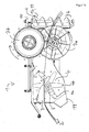
- the device 1 comprises a growth aid guide 3 which is designed as an upwardly open guide channel with an approximately U-shaped cross-section perpendicular to the longitudinal axis of a growth aid 2 lying in the growth aid guide.
- the growth aid guide 3 By means of the growth aid guide 3, the growth aids 2 are guided in particular in the region of a detaching unit 4 of the device 1. This is especially true in the FIGS. 1a . 4a and 3 seen.
- the detaching unit 4 comprises a plurality of detachment elements, of which in FIG. 1a .
- FIG. 4a and 4b two detachment elements 4a and 4b are exemplified.
- the release elements are each designed as a cutting blade, which are mounted on a common shaft 5 and can be rotated by means of a first motor 6.
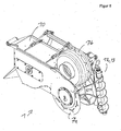
- the device 1 further comprises a plant guide unit 7, which comprises a lower feed wheel 7a and an upper feed wheel 7b.
- the feed wheels 7a and 7b are driven in opposite directions by means of a second motor 8, according to the arrows in FIG FIG. 1a ,
- the device 1 To use the device 1, this is attached by means of a laterally arranged holder 9 on a (not shown) holding device, which holding device is in turn attached to a (not shown) tractor.
- the holding device By means of the holding device, the device 1 can be varied with respect to the height and with respect to the lateral orientation in the direction of travel right in front of the tractor.
- the trellis wires concerned To use the device in a vineyard, for example with Guyot or cordon education (these examples are not limitative), either the trellis wires concerned must be removed by hand from the support posts along a row of grape vines or by means of appropriate holding devices, such as upwardly open clamping hooks, be attached to the support post so that they can be pulled off to the top. At the first and last post of a grapevine line, the trellis wires are permanently attached.
- the device is brought to a position near the first post and the upper Einzugsrad 7b and a top cover 10 (see FIGS. 4 and 6 ) are folded away by pivoting, so that the top view according to FIG. 4a results (with the folded-away elements are not shown) and the trellis wires 2 are placed from above on the lower feed wheel 7a and introduced into the growth aid guide 3 from above. Subsequently, upper cover 10 and upper feed wheel 7b are returned to the original position.
- the growth aids 2 thus run between upper feed wheel 7b and lower feed wheel 7a (see FIG. 3 ) and through the growth guide 3 and thus also between the release elements of the release unit 4 through (see FIGS. 2a and 4a ).
- the two detachment elements, between which the growth aid is guided preferably have a distance to one another in the axial direction in the range of 10 mm to 50 mm, preferably in the range of 20 mm to 40 mm, particularly preferably in the range of 25 mm to 35 mm, more preferably about 30 mm up. More preferably, the growth aid is guided approximately centrally between these two detachment elements. In the exemplary embodiment described here, the two detachment elements 4, between which the growth aids 2 are guided approximately centrally, have a distance from each other in the axial direction of 31 mm.
- the apparatus 1 is moved over the posts of the grapevine line by means of the tractor, so that the trellis wires 2 are pulled upwards out of the holders of the posts, unless they have already been removed from corresponding holders.
- the tractor now moves along the grapevine line, so that the growth aids 2 are passed through the device 1 during this movement.
- the direction of movement of the device is indicated by an arrow C and the relative movement of the growth aids 2 to the device 1 by an arrow D, which relative movement is correspondingly opposite to the direction of movement C of the device 1.
- Plant parts adhering to the trellis wires, in particular vine shoots, are thus guided between the feed wheels 7a and 7b and optionally compressed by compression and supplied to the detaching unit 4 (together with the growth aid 2 moving relative to the device 1).
- the trained as cutting blades, rotating detachment elements 4a, 4a 'and 4b solve the plant parts of the growth aids 2, by chopping, knocking and / or dismemberment.
- the growth aid guide 3 By means of the growth aid guide 3 it is ensured that the growth aids 2 do not come into contact with the detachment elements 4a, 4a 'and 4b of the detaching unit 4 and thus are not damaged by them and in particular are not severed.
- the release elements 4a, 4b rotate in the view in FIG. 1a clockwise as indicated by arrow E. This means that in particular above the shaft 5, the detachment elements 4a, 4a 'and 4b move in the opposite direction to the growth aid 2 and plant parts adhering to the growth aid. This ensures a particularly efficient detachment.
- the detached plant parts are at an outlet 11 (see FIGS. 1, 1 a and 2).
- the growth aids 2 are again secured in appropriate brackets to the posts of the grapevine line.
- the detaching unit of the device 1 comprises a plurality of detaching elements 4. These are arranged rotatably on a common axis, in particular in the FIGS. 1a . 4a and 4b seen. By way of example, three detachment elements 4a, 4a 'and 4b are provided with reference numerals.
- the growth aid guide 3 extends in the radial direction to the axis of rotation of the detachment elements 4 and extends between the two central detachment elements 4a and 4a '.
- the growth aids 2 are thus guided centrally by means of the growth aid guide 3 between the detachment units 4a and 4a 'and above the axis of rotation of the detachment units 4.
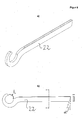
- FIGS. 10 to 13 show schematically the embodiment of the release element 4a ', the release element 4a is in each case designed in mirror image as described above.
- the following is based on the FIGS. 10 to 13 describes the configuration of the release element 4a ', the same applies under consideration of the above-described mirror image design for release element 4a.
- the detaching element 4a ' has longitudinal extensions on both sides, starting from the axis of rotation, wherein in each case, the edges pointing in operation in the direction of rotation (the direction of rotation is in FIG. 10 indicated by arrows) a bevel 30 is formed.
- the bevel 30 is formed on the side facing away from the growth aid 2 of the detachment element 4a '.
- FIG. 10 Accordingly, the side facing away from the operation of the growth aid side of the release element 4a '.
- the bevel 30 has a bevel angle y of 30 °. On the side of the release element 4a 'facing the growth aid 2, on the other hand, no bevel is formed.
- a further reduction of the risk of damage to the growth aid 2 in contact with the release element 4a ' is achieved in that, as in FIG. 10 it can be seen that the detaching element 4a 'has, at the edges which, when operating in the direction of rotation, edges which have a bevel 30, projected on a plane perpendicular to the axis of rotation, have a course which is curved in a direction opposite to the direction of rotation.
- the course is arcuate and has different radii of curvature in different segments:
- the bevel in a first segment has a radius of curvature of 10 cm (R100), and in subsequent segments subsequent arc radii of 25 cm (R250) and 4 cm (R40) on.
- R100 radius of curvature
- R250 radius of curvature
- R40 radius of curvature
- the total length of in FIG. 10 is approximately 45 cm, the length of the first portion with radius of curvature 10 cm is about 5 cm, the length of the second portion with radius of curvature 25 cm is about 12 cm.
- the release element 4a ' is further rounded in the end region on the side lying in operation in the direction of rotation in a plane perpendicular to the axis of rotation. This is in FIG. 10 at the end of radius 4 cm (R40).
- this distance increase in the device according to the invention in the range 1 cm to 8 cm, preferably 2 cm to 6 cm, more preferably 3 cm to 5 cm.
- the rectilinear edge portions 32 of the release element 4a ' have a length of about 2 cm.
- the release element 4a ' according to FIG. 10 thus has several features, each taken to achieve a repellent effect on the growth aid 2 and thus reduce the risk of damage and in particular a severing of the growth aid 2 in contact with the release element 4a 'respectively.
- the formation of the bevel only on the side facing away from the growth aid 2 the formation of no bevel on the side facing each side of the operation in the direction of rotation facing edges and the double arcuate or approximately arcuate configuration of the release element 4a ', on the one hand at Projection on a plane perpendicular to the axis of rotation ( FIG. 10 ) and on the other hand when projecting on a plane parallel to the axis of rotation ( FIG. 11a ).
- a release element 4 is given in particular in the middle, arranged directly on the growth aid 2 detachment elements 4a and 4a '.
- the more widely spaced, also designed as a cutting blade release elements can be designed differently for cost savings, in particular plan in projection on a plane parallel to the axis of rotation.
- the device 1 in addition to the lower feed wheel 7a designed as an upper feed wheel 7b counter element, ie a Schmidteinzugsrad, which are driven in opposite directions.
- the lateral surface 20 a plurality of pairs of recesses, of which in FIG. 7 by way of example the pairs 21 ', 21 "and 21"' are marked.
- retraction elements 22 of which, for example, in FIG. 9 three feeder elements 22a, 22b and 22c are marked.
- the lateral surface 20 is octagonal in cross-section, wherein the eight thereby resulting sections of the lateral surface of the lower Einzugsrades 7a each have two recesses and thus each penetrated by a pair of intake elements 22.
- FIG. 9 is due to the central section in the sectional view only one feeder element 22 of the pairs of feeder elements to see.
- the catchment elements 22 are rotatable about a common axis of rotation (reference G in FIG. 9 ) rotatably arranged.
- the rotation axis G is arranged parallel to the axis of rotation H of the lower feed wheel 7a and spaced therefrom. Due to the arrangement of the upper feed wheel 7b arranged approximately vertically above the axis of rotation H of the lower feed wheel 7a axis of rotation results in the FIG. 9 by "X" marked compression area, which essentially represents the area between the longitudinal extents of the two feed wheels.
- the axis of rotation G is both in the direction of movement C of the device forward, as well as in one of the Compression region facing away from the axis of rotation H of the lower feed wheel 7a spaced.
- catchment elements in a forward position with respect to the direction of movement of the device for example catchment element 22a in FIG. 9 further protrudes from the lateral surface 20 of the lower feed wheel 7a, as in a position to the rear, for example, when due to the rotation of the feed wheel 7a, the collection element 22a, the position of the feeder element 22c in FIG. 9 has reached.
- plant parts adhering to the growth aids 2 are thus additionally captured by the intake elements 22 and guided into the compression region between the two intake wheels 7a and 7b.
- the feeder elements already protrude less from the lateral surface 20 and in a position to the rear, for example, according to retraction element 22c in FIG. 9
- the feeder elements do not protrude or only slightly out of the lateral surface.
- the catchment elements thus release the plant parts in the rearward position, so that wrapping of the feed wheel 7a through the plant parts is avoided and, moreover, an action of the catchment elements on the growth aids 2 in this position is avoided.
- FIG. 7 It can be seen that the distance of the recesses 21 'over 21 "to 21'” respectively decreases.
- the groups of these recesses penetrating intake elements thus have in the direction of rotation of the feed wheel to an increasing distance in the axial direction. This ensures that a laterally slipped growth aid, for example, at position I in FIG. 7 is brought back to a central position (position J) upon rotation of the lower feed wheel 7a by the decreasing distance between the intake elements of a group.
- the pairwise arrangement of the intake elements 22 on the common axis of rotation next to each other is also in the sectional view according to FIG. 4b seen.
- the lower feed wheel 7a has an approximately trough-shaped cross-section parallel to the axis of rotation, wherein starting from a central position in the axial direction of the radius increases toward the outside.
- the feed wheel 7a has pull-in webs 23 extending parallel to the axis of rotation, which have a U-shaped region 23a for centrally guiding the growth aids in the axially central position and a plurality of serrated formations 23b for better collection of the plant parts.
- the collection elements 22 are elongated with rectangular cross section and have according to sectional view BB on the lying in the direction of rotation (top in FIG. 8 ) rounded edges. At the side facing away from the axis of rotation, the feeder elements 22 have a clearance angle ⁇ of 10 °, whereby the collection effect on the plant parts is increased.
- the feeder elements On the side facing the axis of rotation, the feeder elements have a C-profile for gripping around the sleeve surrounding the axis of rotation.
- the opening L of the C-profile is chosen such that it is smaller than the outer radius of the sleeve.
- the feed finger 22 can not be detached from the sleeve and thus not from the axis of rotation. If, however, the sleeve is displaced in the axial direction, so that the C-profile engages directly around the axis of rotation, the retraction element 22 can be removed, since the distance L is greater than the diameter of the axis of rotation.
- the pair of feed elements 22 with the shortest distance has a length of about 17 cm.
- the length of the intake elements 22 increases with increasing distance in the axial direction between the pairs up to a length of about 22 cm of the intake elements with the maximum distance in the axial direction.
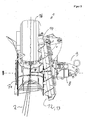
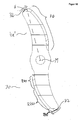
- the plant guide unit 7 is due to the configuration with the lower feed wheel 7a and the upper feed wheel 7b, which parallel axes of rotation have, in particular for the entry of plant parts which extend approximately along the growth aids 2 and of plant parts, which in the front view according to FIG. 3 are approximately perpendicular, ie plant parts whose longitudinal extent is at least in projection on a plane perpendicular to the growth aids 2 approximately perpendicular to the axis of rotation of the lower feed wheel 7a and thus also perpendicular to the axis of rotation of the upper feed wheel 7b.
- In projecting from the growth aids 2 parts of the plant at least in projection on a perpendicular to the growth aids 2 level one in the illustration in FIG.
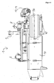
- the plant alignment unit 12 therefore comprises a transport means 13 designed as a screw conveyor.
- the plant transport means 13 thus constitutes a linear conveying means.
- the plant alignment unit 12 further comprises a holder in which the plant transporting means 13 is rotatably mounted and a third motor 14 for rotating the screw conveyor of the plant transport means of the plant alignment unit 12 about the axis of the screw conveyor.
- the plant alignment unit 12 is arranged in front of the plant guide unit 7 with regard to the relative movement of the growth aid guide to the device. Plant parts adhering to the growth aids 2 thus reach first into the area of action of the plant alignment unit 12 and then into the area of action of the plant guidance unit 7.
- Plant parts which project laterally from the growth aids 2 can thus be grasped and moved by the plant transport means 13.
- the direction of rotation is chosen such that the plant parts detected by the plant transport means 13 in FIG. 3 to be moved upwards.
- FIG. 3 Exemplary is in FIG. 3 as a dotted line a plant part F shown schematically, which is approximately perpendicular to the growth aids 2 and horizontally as shown in FIG FIG. 3 projects.
- the plant part F is detected by the plant transport means 13 and with its in FIG. 3 moved right end up, so that the plant part F rotation about the growth aids 2 in the counterclockwise direction in the illustration FIG. 3 performs.
- the plant part F is further approximated the plant guide unit 7, but applies to this in a vertical or nearly vertical orientation as shown in FIG. 3 and can thus be fed easily with the plant guide unit 7.
- Trained as a screw conveyor plant transport means 13 has in the axial extent a length of about 60 cm with a screw pitch of about 12.5 cm and a diameter of about 12.5 cm.
- the part of the transporting means 13 designed as a screw conveyor is operated by means of the third motor 14 at a rotational speed of about 220 rpm.
- the plant guide unit 7 is due to the design with the lower feed wheel 7a and the upper feed wheel 7b, which have parallel axes of rotation, in particular for the entry of plant parts which extend approximately along the growth aids 2 and of plant parts, which in the front view according to FIG. 3 are approximately perpendicular, ie plant parts whose longitudinal extent is at least in projection on a plane perpendicular to the growth aids 2 approximately perpendicular to the axis of rotation of the lower feed wheel 7a and thus also perpendicular to the axis of rotation of the upper feed wheel 7b.
- the plant alignment unit 12 comprises a plant transport means 13 designed as a screw conveyor.
- the plant transport means 13 thus constitutes a linear conveying means.
- the plant alignment unit 12 further comprises a holder in which the plant transporting means 13 is rotatably mounted and a third motor 14 for rotating the screw conveyor of the plant transport means of the plant alignment unit 12 about the axis of the screw conveyor.
- the plant alignment unit 12 is arranged in front of the plant guide unit 7 with regard to the relative movement of the growth aid guide to the device. Plant parts adhering to the growth aids 2 thus reach first into the area of action of the plant alignment unit 12 and then into the area of action of the plant guidance unit 7.
- Plant parts which project laterally from the growth aids 2 can thus be grasped and moved by the plant transport means 13.
- the direction of rotation is chosen such that the plant parts detected by the plant transport means 13 in FIG. 3 to be moved upwards.
- FIG. 3 Exemplary is in FIG. 3 as a dotted line a plant part F shown schematically, which is approximately perpendicular to the growth aids 2 and horizontally as shown in FIG FIG. 3 projects.
- the plant part F is detected by the plant transport means 13 and with its in FIG. 3 moved right end up, so that the plant part F rotation about the growth aids 2 in the counterclockwise direction in the illustration FIG. 3 performs.
- the plant part F is further approximated the plant guide unit 7, but applies to this in a vertical or nearly vertical orientation as shown in FIG. 3 and can thus be fed easily with the plant guide unit 7.
- Trained as a screw conveyor plant transport means 13 has in the axial extent a length of about 60 cm with a screw pitch of about 12.5 cm and a diameter of about 12.5 cm.
- the diameter of the screw decreases continuously toward the respective end of the axis of the screw.
- the part of the transporting means 13 designed as a screw conveyor is operated by means of the third motor 14 at a rotational speed of about 220 rpm.
Landscapes
- Life Sciences & Earth Sciences (AREA)
- Environmental Sciences (AREA)
- Botany (AREA)
- Biodiversity & Conservation Biology (AREA)
- Ecology (AREA)
- Forests & Forestry (AREA)
- Cultivation Of Plants (AREA)
Priority Applications (1)
| Application Number | Priority Date | Filing Date | Title |
|---|---|---|---|
| EP11001170A EP2486788A1 (fr) | 2011-02-14 | 2011-02-14 | Dispositif destiné à supprimer des éléments de plantes d'une aide à la croissance |
Applications Claiming Priority (1)
| Application Number | Priority Date | Filing Date | Title |
|---|---|---|---|
| EP11001170A EP2486788A1 (fr) | 2011-02-14 | 2011-02-14 | Dispositif destiné à supprimer des éléments de plantes d'une aide à la croissance |
Publications (1)
| Publication Number | Publication Date |
|---|---|
| EP2486788A1 true EP2486788A1 (fr) | 2012-08-15 |
Family
ID=44340304
Family Applications (1)
| Application Number | Title | Priority Date | Filing Date |
|---|---|---|---|
| EP11001170A Withdrawn EP2486788A1 (fr) | 2011-02-14 | 2011-02-14 | Dispositif destiné à supprimer des éléments de plantes d'une aide à la croissance |
Country Status (1)
| Country | Link |
|---|---|
| EP (1) | EP2486788A1 (fr) |
Cited By (1)
| Publication number | Priority date | Publication date | Assignee | Title |
|---|---|---|---|---|
| EP2823704A3 (fr) * | 2013-07-11 | 2015-04-22 | ERO-GERÄTEBAU GmbH | Dispositif et procédé destinés à enlever des parties de plantes |
Citations (5)
| Publication number | Priority date | Publication date | Assignee | Title |
|---|---|---|---|---|
| FR2700917A1 (fr) * | 1993-02-01 | 1994-08-05 | Guelle Jean Marie | Prétailleuse pour vigne palissée. |
| WO1997036473A2 (fr) * | 1996-04-01 | 1997-10-09 | Fontan Gerard | Tailleuse elevatrice separatrice |
| FR2811860A1 (fr) * | 2000-07-19 | 2002-01-25 | Lagarde Sas | Lame de coupe pour machine agricole |
| DE102004031088A1 (de) | 2004-06-28 | 2006-01-19 | Manfred Bermes | Verfahren zum Entfernen von Zweigen aus einem Spalier und Vorrichtung dazu |
| WO2009051498A2 (fr) | 2007-10-19 | 2009-04-23 | Honeypot Holdings Limited | Procédé et appareil d'extraction de matériau d'une conduite |
-
2011
- 2011-02-14 EP EP11001170A patent/EP2486788A1/fr not_active Withdrawn
Patent Citations (5)
| Publication number | Priority date | Publication date | Assignee | Title |
|---|---|---|---|---|
| FR2700917A1 (fr) * | 1993-02-01 | 1994-08-05 | Guelle Jean Marie | Prétailleuse pour vigne palissée. |
| WO1997036473A2 (fr) * | 1996-04-01 | 1997-10-09 | Fontan Gerard | Tailleuse elevatrice separatrice |
| FR2811860A1 (fr) * | 2000-07-19 | 2002-01-25 | Lagarde Sas | Lame de coupe pour machine agricole |
| DE102004031088A1 (de) | 2004-06-28 | 2006-01-19 | Manfred Bermes | Verfahren zum Entfernen von Zweigen aus einem Spalier und Vorrichtung dazu |
| WO2009051498A2 (fr) | 2007-10-19 | 2009-04-23 | Honeypot Holdings Limited | Procédé et appareil d'extraction de matériau d'une conduite |
Cited By (1)
| Publication number | Priority date | Publication date | Assignee | Title |
|---|---|---|---|---|
| EP2823704A3 (fr) * | 2013-07-11 | 2015-04-22 | ERO-GERÄTEBAU GmbH | Dispositif et procédé destinés à enlever des parties de plantes |
Similar Documents
| Publication | Publication Date | Title |
|---|---|---|
| DE10113379B4 (de) | Vorschubeinrichtung, insbesondere für Cordbänder | |
| DE102012214741A1 (de) | Vorrichtung und Verfahren zum Aufschneiden von Lebensmittelprodukten | |
| EP0860044A1 (fr) | Dispositif de denudage | |
| EP1997595A1 (fr) | Dispositif de coupe destiné à la coupe de matériaux en bandes, en particulier de bandes de textile ou de corde en acier | |
| EP2537651A1 (fr) | Procédé et dispositif de coupe d'un tronçon d'aliments en tranches | |
| EP2649882B1 (fr) | Dispositif de séparation et de mise en forme de pâte | |
| EP2486787B1 (fr) | Dispositif destiné à supprimer des éléments de plantes d'une aide à la croissance | |
| EP2853149B1 (fr) | Dispositif de tirage de sarments de vignes | |
| DE102009027260B4 (de) | Jätvorrichtung, insbesondere für Wasserpflanzen sowie Jätboot mit einer solchen Vorrichtung | |
| EP2823704B1 (fr) | Dispositif et procédé destinés à enlever des parties de plantes | |
| DD213583B5 (de) | Silagegutschneider | |
| EP3359356B1 (fr) | Dispositif pour couper un tronçon d'aliments | |
| EP2486788A1 (fr) | Dispositif destiné à supprimer des éléments de plantes d'une aide à la croissance | |
| EP2486786A1 (fr) | Procédé et dispositif destinés à supprimer des éléments de plantes d'un fil de support | |
| EP2486789A1 (fr) | Dispositif destiné à supprimer des éléments de plantes d'une aide à la croissance | |
| DE102020116575B4 (de) | Vorrichtung und Verfahren zur zumindest seitlichen Zuschneidung eines Kartonrohlings | |
| DE102005003204B3 (de) | Vorrichtung zum Querschneiden von einer Materialbahn in einzelne Materialabschnitte | |
| EP2803609A1 (fr) | Machine d'enroulement de matériaux en forme de bande | |
| DE102016115497A1 (de) | Haspelwechselvorrichtung und Haspelwechselverfahren | |
| DE102007049344B4 (de) | Vorrichtung zur Entlaubung, insbesondere von Weinstöcken | |
| EP3651563B1 (fr) | Dispositif permettant d'empêcher toute accumulation de fanes et machine de récolte associée | |
| AT505654B1 (de) | Verfahren und vorrichtung zum ausgeizen von geiztrieben | |
| AT12931U1 (de) | Verfahren zum Auftrennen von Pflanzenteilen mit vorwiegend parallel zueinander angeordneten Fasern | |
| AT525287A4 (de) | Vorrichtung zum zerlegen von drahtseilen | |
| DE10017157A1 (de) | Scheibenablagevorrichtung für eine Aufschnittschneidemaschine |
Legal Events
| Date | Code | Title | Description |
|---|---|---|---|
| PUAI | Public reference made under article 153(3) epc to a published international application that has entered the european phase |
Free format text: ORIGINAL CODE: 0009012 |
|
| AK | Designated contracting states |
Kind code of ref document: A1 Designated state(s): AL AT BE BG CH CY CZ DE DK EE ES FI FR GB GR HR HU IE IS IT LI LT LU LV MC MK MT NL NO PL PT RO RS SE SI SK SM TR |
|
| AX | Request for extension of the european patent |
Extension state: BA ME |
|
| 17P | Request for examination filed |
Effective date: 20121106 |
|
| STAA | Information on the status of an ep patent application or granted ep patent |
Free format text: STATUS: EXAMINATION IS IN PROGRESS |
|
| 17Q | First examination report despatched |
Effective date: 20170227 |
|
| STAA | Information on the status of an ep patent application or granted ep patent |
Free format text: STATUS: THE APPLICATION IS DEEMED TO BE WITHDRAWN |
|
| 18D | Application deemed to be withdrawn |
Effective date: 20170711 |