EP2486786A1 - Procédé et dispositif destinés à supprimer des éléments de plantes d'un fil de support - Google Patents
Procédé et dispositif destinés à supprimer des éléments de plantes d'un fil de support Download PDFInfo
- Publication number
- EP2486786A1 EP2486786A1 EP11001168A EP11001168A EP2486786A1 EP 2486786 A1 EP2486786 A1 EP 2486786A1 EP 11001168 A EP11001168 A EP 11001168A EP 11001168 A EP11001168 A EP 11001168A EP 2486786 A1 EP2486786 A1 EP 2486786A1
- Authority
- EP
- European Patent Office
- Prior art keywords
- plant
- growth aid
- unit
- range
- growth
- Prior art date
- Legal status (The legal status is an assumption and is not a legal conclusion. Google has not performed a legal analysis and makes no representation as to the accuracy of the status listed.)
- Withdrawn
Links
Images


Classifications
-
- A—HUMAN NECESSITIES
- A01—AGRICULTURE; FORESTRY; ANIMAL HUSBANDRY; HUNTING; TRAPPING; FISHING
- A01G—HORTICULTURE; CULTIVATION OF VEGETABLES, FLOWERS, RICE, FRUIT, VINES, HOPS OR SEAWEED; FORESTRY; WATERING
- A01G17/00—Cultivation of hops, vines, fruit trees, or like trees
- A01G17/02—Cultivation of hops or vines
- A01G17/023—Machines for priming and/or preliminary pruning of vines, i.e. removing shoots and/or buds
-
- A—HUMAN NECESSITIES
- A01—AGRICULTURE; FORESTRY; ANIMAL HUSBANDRY; HUNTING; TRAPPING; FISHING
- A01G—HORTICULTURE; CULTIVATION OF VEGETABLES, FLOWERS, RICE, FRUIT, VINES, HOPS OR SEAWEED; FORESTRY; WATERING
- A01G3/00—Cutting implements specially adapted for horticultural purposes; Delimbing standing trees
- A01G3/04—Apparatus for trimming hedges, e.g. hedge shears
- A01G3/0408—Apparatus for trimming hedges, e.g. hedge shears specially adapted for trellis work, e.g. machines for pruning vine or the like
Definitions
- the invention relates to a device and a method for removing parts of plants from at least one elongated, tensile stable, limp growth aid during movement of the device along the growth aid according to the preambles of claims 1 and 14.
- pliable growth aids such as ropes or wires are known to support the plants and / or to influence the growth of the plants.
- pliable growth aids such as ropes or wires
- in viticulture the use of trellis wires is known, for example in Guyot and also in cordon education.
- WO 2009/051498 A2 an apparatus and a method for removing parts of plants from a growth aid is known, wherein adhering to the growth aid plant parts are compressed by means of a plant supply unit and / or supplied to a detaching unit.
- the detaching unit comprises at least one detaching element, such as a rotating cutting blade, by means of which the plant parts are at least partially detached from the growth aid.
- the growth aid is guided during the machining process by means of a growth aid guide in order to avoid in particular damage to the growth aid guide by the detachment element.
- the plant parts can grow irregularly and in particular after cutting off the main plant in different directions and in different lengths of the growth aid can stand so high demands on the method and device for removing consist of all the forms of plant parts.
- the plant parts can by wrapping and / or ramifications have a stable connection with the growth aid, which is difficult to solve.
- the present invention is therefore based on the object to improve the prior art devices and methods for removing parts of plants from a growth aid and to reduce the susceptibility to errors and the resulting interruptions during operation.
- the device according to the invention for removing parts of plants from at least one elongated, tensile stable, non-limp growth aid during a movement of the device along the growth aid comprises a growth aid guide for guiding the growth aid during the movement of the device along the growth aid. Furthermore, the device comprises a detachment unit. The apparatus further comprises a plant guide unit for compressing and / or feeding the plant parts adhering to the growth aid to the detachment unit.
- the detachment unit comprises at least one detachment element, which detachment element is movably arranged on the device in such a way that, when operated by movement of the detachment element, plant parts are at least partially detachable from the growth aid.
- the device additionally comprises at least one plant alignment unit with at least one motor-driven plant transport means.
- the plant alignment unit is arranged in front of the plant guide unit with regard to the relative movement of the growth aid guide to the device, ie plants adhering to the growth aid first move to the plant alignment unit and then to the plant guidance unit during the movement of the device, optionally with the interposition of further intermediate elements.
- the plant alignment unit is arranged and designed to move plant parts projecting from the growth aid by means of the plant transporting means in the direction of a preferred intake orientation of the plant management unit.
- the invention is based on the recognition of the Applicant that in particular due to the irregular growth in the direction of movement of the device in front of the plant management unit often faults occur so that plant parts dammed in front of the plant management unit or at least in unfavorable collection positions for compressing and / or feeding through the plant management unit , This causes the following errors in particular:
- the ratio between the operating and maintenance period of the device according to the invention is significantly improved and thus increases the efficiency.
- the device according to the invention or an advantageous embodiment thereof is preferably designed for carrying out the method according to the invention or a preferred embodiment thereof.
- the method according to the invention or a preferred embodiment thereof is preferably designed for implementation by means of the device according to the invention or an advantageous embodiment thereof.
- the plant alignment unit is arranged and designed to rotate by means of the plant transport means from the growth aid projecting plant parts.
- the rotation takes place about an axis of rotation, which axis of rotation coincides approximately with the longitudinal axis of the growth aid in the region of the plant alignment unit.
- the plant transport agent is preferably designed as a linear conveyor. This results in a robust and cost-effective design of the conveyor and at the same time an efficient and error-prone orientation of the growing aid projecting plant parts in the direction of a preferred feed orientation of the plant supply unit.
- the formation of the plant transport means is a screw conveyor.
- Investigations by the applicant have shown that a screw conveyor is robust and at the same time inexpensively formed, for example, by the known in metal screw conveyors, which are rotated by means of a motor, such as a hydraulic motor or an electric motor to the axis of symmetry of the worm shaft.
- a linear transport of the portion of the plant part, which comes into contact with the screw is achieved in a simple manner. Due to the linear transport a rotation of the plant part is achieved by the growth aid in a simple manner due to the adherence of the plant part of the growth aid.
- the formation of the plant transport means as screw conveyor also has the advantage that in case of wrapping the screw conveyor by plants or other objects such can be corrected manually in a short time and beyond there is only a small risk of injury, even if a user in the company the rotating screw conveyor should come into contact.
- the screw conveyor is preferably formed at one end, preferably tapered at both ends. This means that in the axial direction to the respective end, the pitch of the screw is reduced. Applicant's investigations have shown that such conical feeding virtually eliminates errors due to wrapping of the screw by plant parts.
- the plant alignment unit preferably comprises a motor drive for rotating the conveyor screw. Investigations by the Applicant have shown that, in particular, it is advantageous to rotate the screw conveyor at a speed of rotation in the range from 100 rpm to 400 rpm, preferably in the range from 200 rpm to 250 rpm.
- the conveyor screw has a diameter in the range 3 cm to 25 cm, preferably in the range 5 cm to 22 cm, more preferably in the range 9 cm to 20 cm.
- the screw conveyor has a pitch in the range 10 cm to 15 cm, preferably about 12.5 cm.
- the plant transport means designed as a linear conveyor is arranged with conveying direction at a predetermined angle to the preferred intake orientation of the plant management unit.
- Investigations by the applicant have shown that in particular an arrangement at an angle in the range of 3 ° to 20 °, preferably in the range of 5 ° to 15 °, more preferably about 9 ° is advantageous.
- By the aforementioned preferred angle of attack in plan view from the front of the device according to the invention is achieved that upon rotation of the plant parts to the growth aid they are rotated as far as possible in the direction of preferred feed orientation by the linear conveyor.
- the angle between the conveying direction of the linear conveyor and the preferred feed orientation of the plant management unit by a user is optionally predetermined, in particular that the linear conveyor is pivotally mounted and optionally detectable on the device. This allows the user to optionally optimize the aforementioned angle.
- the linear conveying path of the conveying means preferably has a length in the range from 0.3 m to 1.2 m, preferably in the range from 0.5 m to 0.7 m. Investigations by the Applicant have shown that larger lengths considerably complicate the handling of the device and smaller lengths do not allow sufficient movement of the plant parts in the direction of the preferred orientation of feed.
- the linear conveying path on two or more conveying elements, for example by juxtaposing two or more linear conveyor.
- the distance of the plant alignment unit perpendicular to a plant guide unit passing through growth aid is preferably ⁇ 50 cm and is preferably in the range between 5 cm and 30 cm, more preferably in the range between 10 cm and 20 cm to the growth aid. This ensures that, on the one hand, no balls or bales are produced with the aforementioned negative consequences and, on the other hand, plant rows, which are easily pulled in by the plant management unit, are not unnecessarily loaded by the plant alignment unit.
- the plant transport agent is preferably arranged at a distance ⁇ 50 cm, preferably in the range between 5cm and 30 cm, more preferably in the range between 10 cm and 20 cm to the plant guide unit.
- the inventive method and the device according to the invention are particularly suitable for removing vine shoots of at least one trellis wire in viticulture.
- vine shoots of at least one trellis wire in viticulture.
- from such vine shoots although are cut off from the vine, but still adhere to the trellis wire, as typically vine shoots after the manual pruning.
- the device according to the invention and the method according to the invention can also be applied to other plant-growing operations in which plant parts adhere to an elongated, tension-resistant, pliable growth aid, in particular plant parts already separated from the main plant.
- the device according to the invention preferably comprises a holding device, by means of which the device is arranged on a vehicle such as a tractor.
- the holding device is designed such that the device for removal with respect to the height and the lateral distance to the vehicle can be selectively moved.
- Such holding devices are already known in tractors.
- the plant management unit of the device according to the invention preferably comprises a feed wheel in a manner known per se. Investigations by the applicant have shown that such a feed wheel has a preferred feed direction, which is approximately perpendicular to the axis of rotation of the feed wheel.
- the detachment unit and the auxiliary power guide are configured cooperatively such that, in operation, the detachment element has a spacing in the axial direction in the range of 5 mm to 30 mm, preferably in the range of 10 mm to 20 mm, more preferably approximately 15 mm, to the growth aid ,
- the device according to the invention basically according to the device according to WO 2009/051498 A2 or a preferred embodiment thereof.
- Full reference is made to this prior art and it is expressly incorporated by reference in its entirety.
- the development of the previously known device consists in particular in arranging the plant alignment unit in front of the plant guide unit according to the device according to the invention.
- the plant guide unit of the device according to the invention is preferably designed to guide the growth aid, in particular the feed wheel is preferably formed with a respect to the axis of rotation axially from the sides of the feed wheel towards the center decreasing diameter, so that a central guide the growth aid in the axial direction of the axis of rotation the intake wheel is guaranteed.
- FIGS. 1 to 11 of the WO 2009/051498 and the associated description of the figures in which, according to such a preferred embodiment, a plant alignment unit is added in front of the plant supply unit, as stated above.
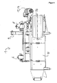
- the device 1 is suitable for removing parts of plants from any elongated, karstabilen, pliable growth aids, such as ropes or wires.
- the device 1 is suitable for use in viticulture to vine shoots, which are cut off from the vine, but still adhere to trained as Trellierdrähten growth aids 2 to remove.
- FIGS. 1 . 1a . 3 . 4a and 5 For better understanding in each case three growth aids 2 are shown.
- the device 1 comprises a growth aid guide 3, which is designed as an upwardly open guide channel with an approximately U-shaped cross-section perpendicular to the longitudinal axis of a growth aid 2 lying in the growth aid guide.
- the growth aid guide 3 By means of the growth aid guide 3, the growth aids 2 are guided in particular in the region of a detaching unit 4 of the device 1. This is especially true in the FIGS. 1a . 4a and 3 seen.
- the detaching unit 4 comprises a plurality of detachment elements, of which in FIG. 1a .
- FIG. 4a and 4b two detachment elements 4a and 4b are exemplified.
- the release elements are each designed as cutting blades, which are mounted on a common shaft 5 and can be set in rotation by means of a first motor 6.
- the device 1 further comprises a plant guide unit 7, which comprises a lower feed wheel 7a and an upper feed wheel 7b.
- the feed wheels 7a and 7b are driven in opposite directions by means of a second motor 8.
- the device 1 To use the device 1 it is attached by means of a laterally arranged holder 9 on a (not shown) holding device, which holding device in turn attached to a (not shown) tractor is.
- the holding device By means of the holding device, the device 1 can be varied with respect to the height and with respect to the lateral orientation in the direction of travel right in front of the tractor.
- either the trellis wires in question must be manually removed from the support posts along a row of vines or by means of appropriate holding devices, such as open topped Clamping hook, be attached to the support post so that they can be pulled off upwards.
- appropriate holding devices such as open topped Clamping hook
- the device is brought to a position near the first post and the upper Einzugsrad 7b and a top cover 10 (see FIGS. 4 and 6 ) are folded away by pivoting, so that the top view according to FIG. 4a results (with the folded-away elements are not shown) and the trellis wires 2 are placed from above on the lower feed wheel 7a and introduced into the growth aid guide 3 from above. Subsequently, the upper cover 10 and the upper pull-in wheel 7b are returned to the original position.
- the growth aids 2 thus run between upper feed wheel 7b and lower feed wheel 7a (see FIG. 3 ) and through the growth aid guide 3 and thus also between the release elements of the release unit 4 (see FIGS. 2a and 4a ).
- the two detachment elements, between which the growth aid is guided preferably have a distance to one another in the axial direction in the range of 10 mm to 50 mm, preferably in the range of 20 mm to 40 mm, particularly preferably in the range of front 25 mm to 35 mm, more preferably about 30 mm up. More preferably, the growth aid is guided approximately centrally between these two detachment elements. In the exemplary embodiment described here, the two detachment elements 4, between which the growth aids 2 are guided approximately centrally, have a distance from each other in the axial direction of 31 mm.
- the apparatus 1 is moved over the posts of the grapevine line by means of the tractor, so that the trellis wires 2 are pulled upwards out of the holders of the posts, unless they have already been removed from corresponding holders.
- the tractor now moves along the grapevine line, so that the growth aids 2 are passed through the device 1 during this movement.
- the direction of movement of the device is indicated by an arrow C and the relative movement of the growth aids 2 to the device 1 by an arrow D, which relative movement is correspondingly opposite to the direction of movement C of the device 1.
- Plant parts adhering to the trellis wires, in particular vine shoots, are thus guided between the feed wheels 7a and 7b and optionally compressed by compression and supplied to the detaching unit 4 (together with the growth aid 2 moving relative to the device 1).
- the trained as a cutting blade, rotating detachment elements 4a, 4b solve the plant parts of the growth aids 2, by shredding, knocking and / or dismemberment.
- the growth aid guide 3 By means of the growth aid guide 3 it is ensured that the growth aids 2 do not come into contact with the detachment elements 4a, 4b of the detaching unit 4 and thus are not damaged by them and in particular are not severed.
- the release elements 4a, 4b rotate in the view in FIG. 1 a clockwise, like. indicated by arrow E. This means that, in particular above the shaft 5, the detachment elements 4a, 4b move in the opposite direction to the growth aid 2 and plant parts adhering to the growth aid. This ensures a particularly efficient detachment.
- the detached plant parts are at an outlet 11 (see FIGS. 1, 1 a and 2).
- the growth aids 2 are again secured in appropriate brackets to the posts of the grapevine line.
- the plant guide unit 7 is due to the design with the lower feed wheel 7a and the upper feed wheel 7b, which have parallel axes of rotation, in particular for the entry of plant parts which extend approximately along the growth aids 2 and of plant parts, which in the front view according to FIG. 3 are approximately perpendicular, ie plant parts whose longitudinal extent is at least in projection on a plane perpendicular to the growth aids 2 approximately perpendicular to the axis of rotation of the lower feed wheel 7a and thus perpendicular to the axis of rotation of the upper feed wheel 7b.
- the plant alignment unit 12 comprises a plant transport means 13 designed as a screw conveyor.
- the plant transport means 13 thus constitutes a linear conveying means.
- the plant alignment unit 12 further comprises a holder in which the plant transporting means 13 is rotatably mounted and a third motor 14 for rotating the screw conveyor of the plant transport means of the plant alignment unit 12 about the axis of the screw conveyor.
- the plant alignment unit 12 is arranged in front of the plant guide unit 7 with regard to the relative movement of the growth aid guide to the device. Plant parts adhering to the growth aids 2 thus reach first into the area of action of the plant alignment unit 12 and then into the area of action of the plant guidance unit 7.
- Plant parts which project laterally from the growth aids 2 can thus be grasped and moved by the plant transport means 13.
- the direction of rotation is chosen such that the plant parts detected by the plant transport means 13 in FIG. 3 to be moved upwards.
- FIG. 3 Exemplary is in FIG. 3 as a dotted line a plant part F shown schematically, which is approximately perpendicular to the growth aids 2 and horizontally as shown in FIG FIG. 3 projects.
- the plant part F is detected by the plant transport means 13 and with its in FIG. 3 moved right end up, so that the plant part F rotation about the growth aids 2 in the counterclockwise direction in the illustration FIG. 3 performs.
- the plant part F is further approximated the plant guide unit 7, but applies to this in a vertical or nearly vertical orientation as shown in FIG FIG. 3 on and thus can be easily fed with the plant guide unit 7.
- Trained as a screw conveyor plant transport means 13 has in the axial extent a length of about 60 cm with a screw pitch of about 12.5 cm and a diameter of about 12.5 cm.
- the diameter of the screw decreases continuously toward the respective end of the axis of the screw.
- the part of the conveying device 13 designed as a screw conveyor is operated by means of the third motor 14 at a rotational speed of about 220 rpm.
Landscapes
- Life Sciences & Earth Sciences (AREA)
- Environmental Sciences (AREA)
- Botany (AREA)
- Biodiversity & Conservation Biology (AREA)
- Ecology (AREA)
- Forests & Forestry (AREA)
- Cultivation Of Plants (AREA)
Priority Applications (1)
| Application Number | Priority Date | Filing Date | Title |
|---|---|---|---|
| EP11001168A EP2486786A1 (fr) | 2011-02-14 | 2011-02-14 | Procédé et dispositif destinés à supprimer des éléments de plantes d'un fil de support |
Applications Claiming Priority (1)
| Application Number | Priority Date | Filing Date | Title |
|---|---|---|---|
| EP11001168A EP2486786A1 (fr) | 2011-02-14 | 2011-02-14 | Procédé et dispositif destinés à supprimer des éléments de plantes d'un fil de support |
Publications (1)
| Publication Number | Publication Date |
|---|---|
| EP2486786A1 true EP2486786A1 (fr) | 2012-08-15 |
Family
ID=44242679
Family Applications (1)
| Application Number | Title | Priority Date | Filing Date |
|---|---|---|---|
| EP11001168A Withdrawn EP2486786A1 (fr) | 2011-02-14 | 2011-02-14 | Procédé et dispositif destinés à supprimer des éléments de plantes d'un fil de support |
Country Status (1)
| Country | Link |
|---|---|
| EP (1) | EP2486786A1 (fr) |
Cited By (2)
| Publication number | Priority date | Publication date | Assignee | Title |
|---|---|---|---|---|
| DE102013219651B3 (de) * | 2013-09-27 | 2014-11-20 | ERO-Gerätebau GmbH | Vorrichtung zum Entfernen von Pflanzenteilen von einer Wuchshilfe |
| EP2823704A2 (fr) | 2013-07-11 | 2015-01-14 | ERO-GERÄTEBAU GmbH | Dispositif et procédé destinés à enlever des parties de plantes |
Citations (4)
| Publication number | Priority date | Publication date | Assignee | Title |
|---|---|---|---|---|
| FR2733118A1 (fr) * | 1995-04-21 | 1996-10-25 | Lacoste Philippe | Machine pour eliminer les sarments de vigne tailles |
| WO1997036473A2 (fr) * | 1996-04-01 | 1997-10-09 | Fontan Gerard | Tailleuse elevatrice separatrice |
| DE102004031088A1 (de) | 2004-06-28 | 2006-01-19 | Manfred Bermes | Verfahren zum Entfernen von Zweigen aus einem Spalier und Vorrichtung dazu |
| WO2009051498A2 (fr) | 2007-10-19 | 2009-04-23 | Honeypot Holdings Limited | Procédé et appareil d'extraction de matériau d'une conduite |
-
2011
- 2011-02-14 EP EP11001168A patent/EP2486786A1/fr not_active Withdrawn
Patent Citations (4)
| Publication number | Priority date | Publication date | Assignee | Title |
|---|---|---|---|---|
| FR2733118A1 (fr) * | 1995-04-21 | 1996-10-25 | Lacoste Philippe | Machine pour eliminer les sarments de vigne tailles |
| WO1997036473A2 (fr) * | 1996-04-01 | 1997-10-09 | Fontan Gerard | Tailleuse elevatrice separatrice |
| DE102004031088A1 (de) | 2004-06-28 | 2006-01-19 | Manfred Bermes | Verfahren zum Entfernen von Zweigen aus einem Spalier und Vorrichtung dazu |
| WO2009051498A2 (fr) | 2007-10-19 | 2009-04-23 | Honeypot Holdings Limited | Procédé et appareil d'extraction de matériau d'une conduite |
Cited By (4)
| Publication number | Priority date | Publication date | Assignee | Title |
|---|---|---|---|---|
| EP2823704A2 (fr) | 2013-07-11 | 2015-01-14 | ERO-GERÄTEBAU GmbH | Dispositif et procédé destinés à enlever des parties de plantes |
| DE102013213623A1 (de) | 2013-07-11 | 2015-01-15 | ERO-Gerätebau GmbH | Vorrichtung und Verfahren zum Entfernen von Pflanzenteilen |
| DE102013219651B3 (de) * | 2013-09-27 | 2014-11-20 | ERO-Gerätebau GmbH | Vorrichtung zum Entfernen von Pflanzenteilen von einer Wuchshilfe |
| EP2853149A1 (fr) | 2013-09-27 | 2015-04-01 | ERO-GERÄTEBAU GmbH | Dispositif de tirage de sarments de vignes |
Similar Documents
| Publication | Publication Date | Title |
|---|---|---|
| WO1997017751A1 (fr) | Dispositif de denudage | |
| EP3616491A1 (fr) | Machine de récolte de plantes sarclées | |
| EP2512256B1 (fr) | Dispositif et procédé pour enlever le cartilage costal d'une volaille | |
| EP2486787B1 (fr) | Dispositif destiné à supprimer des éléments de plantes d'une aide à la croissance | |
| EP2853149B1 (fr) | Dispositif de tirage de sarments de vignes | |
| EP2823704B1 (fr) | Dispositif et procédé destinés à enlever des parties de plantes | |
| DD213583B5 (de) | Silagegutschneider | |
| EP2486786A1 (fr) | Procédé et dispositif destinés à supprimer des éléments de plantes d'un fil de support | |
| DE102004031088B4 (de) | Verfahren zum Entfernen von Zweigen aus einem Spalier und Vorrichtung dazu | |
| DE102020116575B4 (de) | Vorrichtung und Verfahren zur zumindest seitlichen Zuschneidung eines Kartonrohlings | |
| EP2486788A1 (fr) | Dispositif destiné à supprimer des éléments de plantes d'une aide à la croissance | |
| EP2486789A1 (fr) | Dispositif destiné à supprimer des éléments de plantes d'une aide à la croissance | |
| EP2457443B1 (fr) | Procédé de torsion mécanique de bandes de pâte | |
| DE2608160C3 (de) | Vorrichtung zum Auslösen abgelängter Drähte aus einem ungeordneten Drahtbündel, insbesondere beim Zuführen der Drähte zu einer Verarbeitungsmaschine | |
| DE102007048757B4 (de) | Vorrichtung und Verfahren zur Entlaubung, insbesondere von Weinstöcken | |
| DE4110582A1 (de) | Verfahren und vorrichtung zum zuschneiden von pflanzen in toepfen, insbesondere von azaleen | |
| EP0815982B1 (fr) | Dispositif de guidage de fil pour le traitement des extrémités de fils | |
| EP2884833B1 (fr) | Dispositif et procédé pour éliminer des rameaux, notamment des sarments, d'un espalier | |
| EP2986102B1 (fr) | Dispositif de prélèvement de fourrage ensilé | |
| EP2599381A1 (fr) | Table de serre ainsi que le procédé de production des plantes dans une serre comprennant une telle table | |
| DE102007049344B4 (de) | Vorrichtung zur Entlaubung, insbesondere von Weinstöcken | |
| DE102007010550A1 (de) | Vorrichtung und Verfahren zum Schälen von länglichem Gemüse | |
| EP2407020A2 (fr) | Barre de coupe pour une moissonneuse | |
| EP3651563B1 (fr) | Dispositif permettant d'empêcher toute accumulation de fanes et machine de récolte associée | |
| AT505654B1 (de) | Verfahren und vorrichtung zum ausgeizen von geiztrieben |
Legal Events
| Date | Code | Title | Description |
|---|---|---|---|
| PUAI | Public reference made under article 153(3) epc to a published international application that has entered the european phase |
Free format text: ORIGINAL CODE: 0009012 |
|
| AK | Designated contracting states |
Kind code of ref document: A1 Designated state(s): AL AT BE BG CH CY CZ DE DK EE ES FI FR GB GR HR HU IE IS IT LI LT LU LV MC MK MT NL NO PL PT RO RS SE SI SK SM TR |
|
| AX | Request for extension of the european patent |
Extension state: BA ME |
|
| STAA | Information on the status of an ep patent application or granted ep patent |
Free format text: STATUS: THE APPLICATION IS DEEMED TO BE WITHDRAWN |
|
| 18D | Application deemed to be withdrawn |
Effective date: 20130216 |