EP2486786A1 - Device and method for removing plant parts from a support line - Google Patents
Device and method for removing plant parts from a support line Download PDFInfo
- Publication number
- EP2486786A1 EP2486786A1 EP11001168A EP11001168A EP2486786A1 EP 2486786 A1 EP2486786 A1 EP 2486786A1 EP 11001168 A EP11001168 A EP 11001168A EP 11001168 A EP11001168 A EP 11001168A EP 2486786 A1 EP2486786 A1 EP 2486786A1
- Authority
- EP
- European Patent Office
- Prior art keywords
- plant
- growth aid
- unit
- range
- growth
- Prior art date
- Legal status (The legal status is an assumption and is not a legal conclusion. Google has not performed a legal analysis and makes no representation as to the accuracy of the status listed.)
- Withdrawn
Links
Images


Classifications
-
- A—HUMAN NECESSITIES
- A01—AGRICULTURE; FORESTRY; ANIMAL HUSBANDRY; HUNTING; TRAPPING; FISHING
- A01G—HORTICULTURE; CULTIVATION OF VEGETABLES, FLOWERS, RICE, FRUIT, VINES, HOPS OR SEAWEED; FORESTRY; WATERING
- A01G17/00—Cultivation of hops, vines, fruit trees, or like trees
- A01G17/02—Cultivation of hops or vines
- A01G17/023—Machines for priming and/or preliminary pruning of vines, i.e. removing shoots and/or buds
-
- A—HUMAN NECESSITIES
- A01—AGRICULTURE; FORESTRY; ANIMAL HUSBANDRY; HUNTING; TRAPPING; FISHING
- A01G—HORTICULTURE; CULTIVATION OF VEGETABLES, FLOWERS, RICE, FRUIT, VINES, HOPS OR SEAWEED; FORESTRY; WATERING
- A01G3/00—Cutting implements specially adapted for horticultural purposes; Delimbing standing trees
- A01G3/04—Apparatus for trimming hedges, e.g. hedge shears
- A01G3/0408—Apparatus for trimming hedges, e.g. hedge shears specially adapted for trellis work, e.g. machines for pruning vine or the like
Definitions
- the invention relates to a device and a method for removing parts of plants from at least one elongated, tensile stable, limp growth aid during movement of the device along the growth aid according to the preambles of claims 1 and 14.
- pliable growth aids such as ropes or wires are known to support the plants and / or to influence the growth of the plants.
- pliable growth aids such as ropes or wires
- in viticulture the use of trellis wires is known, for example in Guyot and also in cordon education.
- WO 2009/051498 A2 an apparatus and a method for removing parts of plants from a growth aid is known, wherein adhering to the growth aid plant parts are compressed by means of a plant supply unit and / or supplied to a detaching unit.
- the detaching unit comprises at least one detaching element, such as a rotating cutting blade, by means of which the plant parts are at least partially detached from the growth aid.
- the growth aid is guided during the machining process by means of a growth aid guide in order to avoid in particular damage to the growth aid guide by the detachment element.
- the plant parts can grow irregularly and in particular after cutting off the main plant in different directions and in different lengths of the growth aid can stand so high demands on the method and device for removing consist of all the forms of plant parts.
- the plant parts can by wrapping and / or ramifications have a stable connection with the growth aid, which is difficult to solve.
- the present invention is therefore based on the object to improve the prior art devices and methods for removing parts of plants from a growth aid and to reduce the susceptibility to errors and the resulting interruptions during operation.
- the device according to the invention for removing parts of plants from at least one elongated, tensile stable, non-limp growth aid during a movement of the device along the growth aid comprises a growth aid guide for guiding the growth aid during the movement of the device along the growth aid. Furthermore, the device comprises a detachment unit. The apparatus further comprises a plant guide unit for compressing and / or feeding the plant parts adhering to the growth aid to the detachment unit.
- the detachment unit comprises at least one detachment element, which detachment element is movably arranged on the device in such a way that, when operated by movement of the detachment element, plant parts are at least partially detachable from the growth aid.
- the device additionally comprises at least one plant alignment unit with at least one motor-driven plant transport means.
- the plant alignment unit is arranged in front of the plant guide unit with regard to the relative movement of the growth aid guide to the device, ie plants adhering to the growth aid first move to the plant alignment unit and then to the plant guidance unit during the movement of the device, optionally with the interposition of further intermediate elements.
- the plant alignment unit is arranged and designed to move plant parts projecting from the growth aid by means of the plant transporting means in the direction of a preferred intake orientation of the plant management unit.
- the invention is based on the recognition of the Applicant that in particular due to the irregular growth in the direction of movement of the device in front of the plant management unit often faults occur so that plant parts dammed in front of the plant management unit or at least in unfavorable collection positions for compressing and / or feeding through the plant management unit , This causes the following errors in particular:
- the ratio between the operating and maintenance period of the device according to the invention is significantly improved and thus increases the efficiency.
- the device according to the invention or an advantageous embodiment thereof is preferably designed for carrying out the method according to the invention or a preferred embodiment thereof.
- the method according to the invention or a preferred embodiment thereof is preferably designed for implementation by means of the device according to the invention or an advantageous embodiment thereof.
- the plant alignment unit is arranged and designed to rotate by means of the plant transport means from the growth aid projecting plant parts.
- the rotation takes place about an axis of rotation, which axis of rotation coincides approximately with the longitudinal axis of the growth aid in the region of the plant alignment unit.
- the plant transport agent is preferably designed as a linear conveyor. This results in a robust and cost-effective design of the conveyor and at the same time an efficient and error-prone orientation of the growing aid projecting plant parts in the direction of a preferred feed orientation of the plant supply unit.
- the formation of the plant transport means is a screw conveyor.
- Investigations by the applicant have shown that a screw conveyor is robust and at the same time inexpensively formed, for example, by the known in metal screw conveyors, which are rotated by means of a motor, such as a hydraulic motor or an electric motor to the axis of symmetry of the worm shaft.
- a linear transport of the portion of the plant part, which comes into contact with the screw is achieved in a simple manner. Due to the linear transport a rotation of the plant part is achieved by the growth aid in a simple manner due to the adherence of the plant part of the growth aid.
- the formation of the plant transport means as screw conveyor also has the advantage that in case of wrapping the screw conveyor by plants or other objects such can be corrected manually in a short time and beyond there is only a small risk of injury, even if a user in the company the rotating screw conveyor should come into contact.
- the screw conveyor is preferably formed at one end, preferably tapered at both ends. This means that in the axial direction to the respective end, the pitch of the screw is reduced. Applicant's investigations have shown that such conical feeding virtually eliminates errors due to wrapping of the screw by plant parts.
- the plant alignment unit preferably comprises a motor drive for rotating the conveyor screw. Investigations by the Applicant have shown that, in particular, it is advantageous to rotate the screw conveyor at a speed of rotation in the range from 100 rpm to 400 rpm, preferably in the range from 200 rpm to 250 rpm.
- the conveyor screw has a diameter in the range 3 cm to 25 cm, preferably in the range 5 cm to 22 cm, more preferably in the range 9 cm to 20 cm.
- the screw conveyor has a pitch in the range 10 cm to 15 cm, preferably about 12.5 cm.
- the plant transport means designed as a linear conveyor is arranged with conveying direction at a predetermined angle to the preferred intake orientation of the plant management unit.
- Investigations by the applicant have shown that in particular an arrangement at an angle in the range of 3 ° to 20 °, preferably in the range of 5 ° to 15 °, more preferably about 9 ° is advantageous.
- By the aforementioned preferred angle of attack in plan view from the front of the device according to the invention is achieved that upon rotation of the plant parts to the growth aid they are rotated as far as possible in the direction of preferred feed orientation by the linear conveyor.
- the angle between the conveying direction of the linear conveyor and the preferred feed orientation of the plant management unit by a user is optionally predetermined, in particular that the linear conveyor is pivotally mounted and optionally detectable on the device. This allows the user to optionally optimize the aforementioned angle.
- the linear conveying path of the conveying means preferably has a length in the range from 0.3 m to 1.2 m, preferably in the range from 0.5 m to 0.7 m. Investigations by the Applicant have shown that larger lengths considerably complicate the handling of the device and smaller lengths do not allow sufficient movement of the plant parts in the direction of the preferred orientation of feed.
- the linear conveying path on two or more conveying elements, for example by juxtaposing two or more linear conveyor.
- the distance of the plant alignment unit perpendicular to a plant guide unit passing through growth aid is preferably ⁇ 50 cm and is preferably in the range between 5 cm and 30 cm, more preferably in the range between 10 cm and 20 cm to the growth aid. This ensures that, on the one hand, no balls or bales are produced with the aforementioned negative consequences and, on the other hand, plant rows, which are easily pulled in by the plant management unit, are not unnecessarily loaded by the plant alignment unit.
- the plant transport agent is preferably arranged at a distance ⁇ 50 cm, preferably in the range between 5cm and 30 cm, more preferably in the range between 10 cm and 20 cm to the plant guide unit.
- the inventive method and the device according to the invention are particularly suitable for removing vine shoots of at least one trellis wire in viticulture.
- vine shoots of at least one trellis wire in viticulture.
- from such vine shoots although are cut off from the vine, but still adhere to the trellis wire, as typically vine shoots after the manual pruning.
- the device according to the invention and the method according to the invention can also be applied to other plant-growing operations in which plant parts adhere to an elongated, tension-resistant, pliable growth aid, in particular plant parts already separated from the main plant.
- the device according to the invention preferably comprises a holding device, by means of which the device is arranged on a vehicle such as a tractor.
- the holding device is designed such that the device for removal with respect to the height and the lateral distance to the vehicle can be selectively moved.
- Such holding devices are already known in tractors.
- the plant management unit of the device according to the invention preferably comprises a feed wheel in a manner known per se. Investigations by the applicant have shown that such a feed wheel has a preferred feed direction, which is approximately perpendicular to the axis of rotation of the feed wheel.
- the detachment unit and the auxiliary power guide are configured cooperatively such that, in operation, the detachment element has a spacing in the axial direction in the range of 5 mm to 30 mm, preferably in the range of 10 mm to 20 mm, more preferably approximately 15 mm, to the growth aid ,
- the device according to the invention basically according to the device according to WO 2009/051498 A2 or a preferred embodiment thereof.
- Full reference is made to this prior art and it is expressly incorporated by reference in its entirety.
- the development of the previously known device consists in particular in arranging the plant alignment unit in front of the plant guide unit according to the device according to the invention.
- the plant guide unit of the device according to the invention is preferably designed to guide the growth aid, in particular the feed wheel is preferably formed with a respect to the axis of rotation axially from the sides of the feed wheel towards the center decreasing diameter, so that a central guide the growth aid in the axial direction of the axis of rotation the intake wheel is guaranteed.
- FIGS. 1 to 11 of the WO 2009/051498 and the associated description of the figures in which, according to such a preferred embodiment, a plant alignment unit is added in front of the plant supply unit, as stated above.
- the device 1 is suitable for removing parts of plants from any elongated, karstabilen, pliable growth aids, such as ropes or wires.
- the device 1 is suitable for use in viticulture to vine shoots, which are cut off from the vine, but still adhere to trained as Trellierdrähten growth aids 2 to remove.
- FIGS. 1 . 1a . 3 . 4a and 5 For better understanding in each case three growth aids 2 are shown.
- the device 1 comprises a growth aid guide 3, which is designed as an upwardly open guide channel with an approximately U-shaped cross-section perpendicular to the longitudinal axis of a growth aid 2 lying in the growth aid guide.
- the growth aid guide 3 By means of the growth aid guide 3, the growth aids 2 are guided in particular in the region of a detaching unit 4 of the device 1. This is especially true in the FIGS. 1a . 4a and 3 seen.
- the detaching unit 4 comprises a plurality of detachment elements, of which in FIG. 1a .
- FIG. 4a and 4b two detachment elements 4a and 4b are exemplified.
- the release elements are each designed as cutting blades, which are mounted on a common shaft 5 and can be set in rotation by means of a first motor 6.
- the device 1 further comprises a plant guide unit 7, which comprises a lower feed wheel 7a and an upper feed wheel 7b.
- the feed wheels 7a and 7b are driven in opposite directions by means of a second motor 8.
- the device 1 To use the device 1 it is attached by means of a laterally arranged holder 9 on a (not shown) holding device, which holding device in turn attached to a (not shown) tractor is.
- the holding device By means of the holding device, the device 1 can be varied with respect to the height and with respect to the lateral orientation in the direction of travel right in front of the tractor.
- either the trellis wires in question must be manually removed from the support posts along a row of vines or by means of appropriate holding devices, such as open topped Clamping hook, be attached to the support post so that they can be pulled off upwards.
- appropriate holding devices such as open topped Clamping hook
- the device is brought to a position near the first post and the upper Einzugsrad 7b and a top cover 10 (see FIGS. 4 and 6 ) are folded away by pivoting, so that the top view according to FIG. 4a results (with the folded-away elements are not shown) and the trellis wires 2 are placed from above on the lower feed wheel 7a and introduced into the growth aid guide 3 from above. Subsequently, the upper cover 10 and the upper pull-in wheel 7b are returned to the original position.
- the growth aids 2 thus run between upper feed wheel 7b and lower feed wheel 7a (see FIG. 3 ) and through the growth aid guide 3 and thus also between the release elements of the release unit 4 (see FIGS. 2a and 4a ).
- the two detachment elements, between which the growth aid is guided preferably have a distance to one another in the axial direction in the range of 10 mm to 50 mm, preferably in the range of 20 mm to 40 mm, particularly preferably in the range of front 25 mm to 35 mm, more preferably about 30 mm up. More preferably, the growth aid is guided approximately centrally between these two detachment elements. In the exemplary embodiment described here, the two detachment elements 4, between which the growth aids 2 are guided approximately centrally, have a distance from each other in the axial direction of 31 mm.
- the apparatus 1 is moved over the posts of the grapevine line by means of the tractor, so that the trellis wires 2 are pulled upwards out of the holders of the posts, unless they have already been removed from corresponding holders.
- the tractor now moves along the grapevine line, so that the growth aids 2 are passed through the device 1 during this movement.
- the direction of movement of the device is indicated by an arrow C and the relative movement of the growth aids 2 to the device 1 by an arrow D, which relative movement is correspondingly opposite to the direction of movement C of the device 1.
- Plant parts adhering to the trellis wires, in particular vine shoots, are thus guided between the feed wheels 7a and 7b and optionally compressed by compression and supplied to the detaching unit 4 (together with the growth aid 2 moving relative to the device 1).
- the trained as a cutting blade, rotating detachment elements 4a, 4b solve the plant parts of the growth aids 2, by shredding, knocking and / or dismemberment.
- the growth aid guide 3 By means of the growth aid guide 3 it is ensured that the growth aids 2 do not come into contact with the detachment elements 4a, 4b of the detaching unit 4 and thus are not damaged by them and in particular are not severed.
- the release elements 4a, 4b rotate in the view in FIG. 1 a clockwise, like. indicated by arrow E. This means that, in particular above the shaft 5, the detachment elements 4a, 4b move in the opposite direction to the growth aid 2 and plant parts adhering to the growth aid. This ensures a particularly efficient detachment.
- the detached plant parts are at an outlet 11 (see FIGS. 1, 1 a and 2).
- the growth aids 2 are again secured in appropriate brackets to the posts of the grapevine line.
- the plant guide unit 7 is due to the design with the lower feed wheel 7a and the upper feed wheel 7b, which have parallel axes of rotation, in particular for the entry of plant parts which extend approximately along the growth aids 2 and of plant parts, which in the front view according to FIG. 3 are approximately perpendicular, ie plant parts whose longitudinal extent is at least in projection on a plane perpendicular to the growth aids 2 approximately perpendicular to the axis of rotation of the lower feed wheel 7a and thus perpendicular to the axis of rotation of the upper feed wheel 7b.
- the plant alignment unit 12 comprises a plant transport means 13 designed as a screw conveyor.
- the plant transport means 13 thus constitutes a linear conveying means.
- the plant alignment unit 12 further comprises a holder in which the plant transporting means 13 is rotatably mounted and a third motor 14 for rotating the screw conveyor of the plant transport means of the plant alignment unit 12 about the axis of the screw conveyor.
- the plant alignment unit 12 is arranged in front of the plant guide unit 7 with regard to the relative movement of the growth aid guide to the device. Plant parts adhering to the growth aids 2 thus reach first into the area of action of the plant alignment unit 12 and then into the area of action of the plant guidance unit 7.
- Plant parts which project laterally from the growth aids 2 can thus be grasped and moved by the plant transport means 13.
- the direction of rotation is chosen such that the plant parts detected by the plant transport means 13 in FIG. 3 to be moved upwards.
- FIG. 3 Exemplary is in FIG. 3 as a dotted line a plant part F shown schematically, which is approximately perpendicular to the growth aids 2 and horizontally as shown in FIG FIG. 3 projects.
- the plant part F is detected by the plant transport means 13 and with its in FIG. 3 moved right end up, so that the plant part F rotation about the growth aids 2 in the counterclockwise direction in the illustration FIG. 3 performs.
- the plant part F is further approximated the plant guide unit 7, but applies to this in a vertical or nearly vertical orientation as shown in FIG FIG. 3 on and thus can be easily fed with the plant guide unit 7.
- Trained as a screw conveyor plant transport means 13 has in the axial extent a length of about 60 cm with a screw pitch of about 12.5 cm and a diameter of about 12.5 cm.
- the diameter of the screw decreases continuously toward the respective end of the axis of the screw.
- the part of the conveying device 13 designed as a screw conveyor is operated by means of the third motor 14 at a rotational speed of about 220 rpm.
Landscapes
- Life Sciences & Earth Sciences (AREA)
- Environmental Sciences (AREA)
- Botany (AREA)
- Biodiversity & Conservation Biology (AREA)
- Ecology (AREA)
- Forests & Forestry (AREA)
- Cultivation Of Plants (AREA)
Abstract
Description
Die Erfindung betrifft eine Vorrichtung und ein Verfahren zum Entfernen von Pflanzenteilen von mindestens einer länglichen, zugstabilen, biegeschlaffen Wuchshilfe während einer Bewegung der Vorrichtung entlang der Wuchshilfe gemäß den Oberbegriffen der Ansprüche 1 und 14.The invention relates to a device and a method for removing parts of plants from at least one elongated, tensile stable, limp growth aid during movement of the device along the growth aid according to the preambles of
Bei dem Anbau von Pflanzen sind längliche, zugstabile, biegeschlaffe Wuchshilfen wie beispielsweise Seile oder Drähte bekannt, um die Pflanzen zu stützen und/oder den Wuchs der Pflanzen zu beeinflussen. So ist beispielsweise im Weinbau die Verwendung von Spalierdrähten bekannt, beispielsweise bei der Guyot- und auch bei der Kordonerziehung.When growing plants elongated, zugstabile, pliable growth aids such as ropes or wires are known to support the plants and / or to influence the growth of the plants. For example, in viticulture the use of trellis wires is known, for example in Guyot and also in cordon education.
Bei dem Anbau von Pflanzen mittels vorgenannter Wuchshilfen ist es typischerweise zu bestimmten Zeitpunkten wünschenswert, Pflanzenteile abzutrennen und die an den Wuchshilfen noch anhaftenden, abgetrennten Pflanzenteile zu entfernen. So ist es beispielsweise im Weinbau üblich, Rebentriebe abzutrennen, beispielsweise mittels eines motorisch angetriebenen Vorschneiders. Eine Vielzahl von abgetrennten Rebentrieben bleibt jedoch nach dem Abtrennen von der Rebenpflanze an der Wuchshilfe haften, aufgrund von Verrankung oder zumindest teilweisem Umschließen der Wuchshilfe durch den Rebentrieb oder einzelne Fortsätze des Rebentriebs.In the cultivation of plants by means of the above-mentioned growth aids, it is typically desirable at certain times to separate plant parts and to remove the growth aids still adherent, separated plant parts. For example, it is customary in viticulture to separate vine shoots, for example by means of a motor-driven pre-cutter. A large number of separated vine shoots, however, remain attached to the growth aid after separation from the vine plant, due to limitation or at least partially surrounding the growth aid by the vine shoot or individual extensions of the vine shoot.
Das Entfernen der an der Wuchshilfe anhaftenden Pflanzenteile erfolgt üblicherweise manuell und stellt einen aufwändigen, mühsamen Arbeitsvorgang dar.The removal of adhering to the growth aid plant parts is usually done manually and represents a complex, tedious operation.
Zur Vereinfachung dieses Vorgangs ist aus der
Aus
Grundsätzlich problematisch bei dem Entfernen von Pflanzenteilen von der Wuchshilfe ist, dass die Pflanzenteile unregelmäßig gewachsen und insbesondere nach einem Abschneiden von der Hauptpflanze in unterschiedlichsten Richtungen und in unterschiedlichen Längen von der Wuchshilfe abstehen können, so dass hohe Anforderungen an das Verfahren und die Vorrichtung zum Entfernen aller Ausgestaltungen der Pflanzenteile bestehen. Darüber hinaus können die Pflanzenteile durch Umwicklungen und/oder Verästelungen eine stabile Verbindung mit der Wuchshilfe aufweisen, die schwierig zu lösen ist.Fundamentally problematic in the removal of plant parts from the growth aid is that the plant parts can grow irregularly and in particular after cutting off the main plant in different directions and in different lengths of the growth aid can stand so high demands on the method and device for removing consist of all the forms of plant parts. In addition, the plant parts can by wrapping and / or ramifications have a stable connection with the growth aid, which is difficult to solve.
Der vorliegenden Erfindung liegt daher die Aufgabe zugrunde, die vorbekannten Vorrichtungen und Verfahren zum Entfernen von Pflanzenteilen von einer Wuchshilfe zu verbessern und die Fehleranfälligkeit und daraus resultierende notwendige Unterbrechungen während des Betriebs zu verringern.The present invention is therefore based on the object to improve the prior art devices and methods for removing parts of plants from a growth aid and to reduce the susceptibility to errors and the resulting interruptions during operation.
Gelöst ist diese Aufgabe durch eine Vorrichtung gemäß Anspruch 1 sowie ein Verfahren gemäß Anspruch 14. Vorteilhafte Ausgestaltungen der Vorrichtung finden sich in den Ansprüchen 2 bis 13. Eine vorteilhafte Ausgestaltung des Verfahrens findet sich in Anspruch 15. Hiermit wird der Wortlaut aller Ansprüche durch ausdrückliche Bezugnahme in die Beschreibung aufgenommen.This object is achieved by a device according to
Die erfindungsgemäße Vorrichtung zum Entfernen von Pflanzenteilen von mindestens einer länglichen, zugstabilen, biegeschlaffen Wuchshilfe während einer Bewegung der Vorrichtung entlang der Wuchshilfe umfasst eine Wuchshilfeführung, zum Führen der Wuchshilfe während der Bewegung der Vorrichtung entlang der Wuchshilfe. Weiterhin umfasst die Vorrichtung eine Ablöseeinheit. Die Vorrichtung umfasst weiterhin eine Pflanzenführungseinheit zum Komprimieren und/oder Zuführen der an der Wuchshilfe anhaftenden Pflanzenteile zu der Ablöseeinheit.The device according to the invention for removing parts of plants from at least one elongated, tensile stable, non-limp growth aid during a movement of the device along the growth aid comprises a growth aid guide for guiding the growth aid during the movement of the device along the growth aid. Furthermore, the device comprises a detachment unit. The apparatus further comprises a plant guide unit for compressing and / or feeding the plant parts adhering to the growth aid to the detachment unit.
Die Ablöseeinheit umfasst mindestens ein Ablöseelement, welches Ablöseelement derart beweglich an der Vorrichtung angeordnet ist, dass bei Betrieb durch Bewegung des Ablöseelementes Pflanzenteile von der Wuchshilfe zumindest teilweise ablösbar sind.The detachment unit comprises at least one detachment element, which detachment element is movably arranged on the device in such a way that, when operated by movement of the detachment element, plant parts are at least partially detachable from the growth aid.
Wesentlich ist, dass die Vorrichtung zusätzlich mindestens eine Pflanzenausrichteinheit mit mindestens einem motorisch angetriebenen Pflanzentransportmittel umfasst. Die Pflanzenausrichteinheit ist vor der Pflanzenführungseinheit angeordnet, hinsichtlich der Relativbewegung der Wuchshilfeführung zu der Vorrichtung, das heißt, dass an der Wuchshilfe anhaftende Pflanzen während der Bewegung der Vorrichtung zunächst zu der Pflanzenausrichteinheit und danach zu der Pflanzenführungseinheit gelangen, gegebenenfalls unter Zwischenschaltung weiterer Zwischenelemente.It is essential that the device additionally comprises at least one plant alignment unit with at least one motor-driven plant transport means. The plant alignment unit is arranged in front of the plant guide unit with regard to the relative movement of the growth aid guide to the device, ie plants adhering to the growth aid first move to the plant alignment unit and then to the plant guidance unit during the movement of the device, optionally with the interposition of further intermediate elements.
Die Pflanzenausrichteinheit ist derart angeordnet und dazu ausgebildet, mittels des Pflanzentransportmittels von der Wuchshilfe abstehende Pflanzenteile in Richtung einer bevorzugten Einzugsorientierung der Pflanzenführungseinheit zu bewegen.The plant alignment unit is arranged and designed to move plant parts projecting from the growth aid by means of the plant transporting means in the direction of a preferred intake orientation of the plant management unit.
Das erfindungsgemäße Verfahren zum Entfernen von Pflanzenteilen von mindestens einer länglichen, zugstabilen, biegeschlaffen Wuchshilfe während einer Bewegung mittels einer Vorrichtung während einer Bewegung der Vorrichtung entlang der Wuchshilfe umfasst folgende Verfahrensschritte:
- Komprimieren und/oder Zuführen von an der Wuchshilfe anhaftenden Pflanzenteilen mittels einer Pflanzenführungseinheit zu einer Ablöseeinheit,
- durch Bewegen eines Ablöseelementes der Ablöseeinheit zumindest teilweises Ablösen der Pflanzenteile von der Wuchshilfe und
- Führen der Wuchshilfe während der Bewegung Vorrichtung entlang der Wuchshilfe mittels einer Wuchshilfeführung.
- Compressing and / or supplying plant parts adhering to the growth aid by means of a plant guiding unit to a detaching unit,
- by moving a release element of the detachment unit at least partial detachment of the plant parts of the growth aid and
- Guide the growth aid during the movement device along the growth aid by means of a growth aid guide.
Wesentlich ist, dass vor dem Komprimieren und/oder zuführen der Pflanzenteile mittels der Pflanzenführungseinheit von der Wuchshilfe abstehende Pflanzenteile mittels eines motorisch angetriebenen Pflanzentransportmittels in Richtung einer bevorzugten Einzugsorientierung der Pflanzenführungseinheit bewegt werden.It is essential that prior to compressing and / or feeding the plant parts by means of the plant management unit projecting from the growth aid plant parts are moved by means of a motor-driven plant transport means in the direction of a preferred feed orientation of the plant management unit.
Die Erfindung ist in der Erkenntnis des Anmelders begründet, dass insbesondere aufgrund des unregelmäßigen Wuchses in Bewegungsrichtung der Vorrichtung vor der Pflanzenführungseinheit häufig Störungen derart auftreten, dass sich Pflanzenteile vor der Pflanzenführungseinheit aufstauen oder zumindest in ungünstigen Einzugspositionen zum Komprimieren und/oder Zuführen durch die Pflanzenführungseinheit befinden. Hierdurch werden insbesondere folgende Fehler verursacht:The invention is based on the recognition of the Applicant that in particular due to the irregular growth in the direction of movement of the device in front of the plant management unit often faults occur so that plant parts dammed in front of the plant management unit or at least in unfavorable collection positions for compressing and / or feeding through the plant management unit , This causes the following errors in particular:
Durch das Aufstauen einer Vielzahl von Pflanzenteilen kann es zu unregelmäßigem Zuführen der Pflanzenteile mittels der Pflanzenführungseinheit zu der Ablöseeinheit kommen, so dass zunächst sich eine Vielzahl von Pflanzenteilen vor der Pflanzenführungseinheit aufstaut und anschließend diese Pflanzenteile in Form eines Knäuels oder großen Ballens der Ablöseeinheit zugeführt werden, so dass häufig aufgrund solch eines Knäuels oder Ballens die Wuchshilfe in einen ungünstigen Verlaufsweg abgelenkt wird, so dass insbesondere ein hohes Risiko besteht, dass die Wuchshilfe durch das Ablöseelement der Ablöseeinheit beschädigt, häufig durchtrennt wird.By damming a plurality of plant parts may lead to irregular feeding of the plant parts by the plant guide unit to the detachment unit, so that initially accumulates a variety of plant parts in front of the plant management unit and then these parts of plants in the form of a ball or large bale of the detachment unit are supplied so that often due to such a ball or bale the growth aid is deflected in an unfavorable course, so that in particular there is a high risk that the growth aid is damaged by the release element of the detachment unit, often severed.
Darüber hinaus kann bereits ein Aufstauen von Pflanzenteilen oder bereits eine ungünstige Orientierung von Pflanzenteile vor der Pflanzenführungseinheit dazu führen, dass trotz des Verwendens einer Wuchshilfeführung die Wuchshilfe in einen ungünstigen Verlaufsweg abgelenkt wird, so dass ebenso ein hohes Risiko besteht, dass die Wuchshilfe durch das Ablöseelement der Ablöseeinheit beschädigt, häufig durchtrennt wird.In addition, already a damming of plant parts or even an unfavorable orientation of plant parts before the plant management unit cause that despite the use of a growth guide the growth aid is deflected in an unfavorable path, so that also a high risk exists that the growth aid is damaged by the release element of the detachment unit, often cut.
Untersuchungen des Anmelders haben gezeigt, dass die Verwendung einer Pflanzenausrichteinheit, welche mittels mindestens eines motorisch angetriebenen Pflanzentransportmittels die Pflanzen zumindest in Richtung einer bevorzugten Einzugsorientierung der Pflanzenzuführungseinheit bewegt, die Bildung vorgenannter Staus und damit das Anhäufen vorgenannter Knäuel oder Ballen vermieden wird.Investigations by the applicant have shown that the use of a plant alignment unit, which moves the plants by means of at least one motor-driven plant transport means at least in the direction of a preferred intake orientation of the plant supply unit, the formation of the aforementioned congestion and thus the accumulation of aforementioned balls or bales is avoided.
Durch die Hinzufügung der Pflanzenausrichteinheit zu der vorbekannten Vorrichtung wird somit in effektiver Weise eine typische Fehlerquelle nahezu vollständig ausgeschlossen, so dass durch diese Fehler begründete Betriebsunterbrechungen und Beschädigungen der Wuchshilfe ebenfalls nahezu ausgeschlossen sind.Thus, by adding the plant alignment unit to the prior art device, a typical source of error is effectively eliminated almost completely so that business interruptions and damage to the growth aid due to these errors are also virtually eliminated.
Hierdurch wird das Verhältnis zwischen Betriebs- und Wartungsdauer der erfindungsgemäßen Vorrichtung erheblich verbessert und damit die Wirtschaftlichkeit erhöht.As a result, the ratio between the operating and maintenance period of the device according to the invention is significantly improved and thus increases the efficiency.
Die erfindungsgemäße Vorrichtung bzw. eine vorteilhafte Ausgestaltung hiervon ist vorzugsweise zur Durchführung des erfindungsgemäßen Verfahrens bzw. einer vorzugsweisen Ausführungsform hiervon ausgebildet. Ebenso ist das erfindungsgemäße Verfahren bzw. eine vorzugsweise Ausführungsform hiervon vorzugsweise zur Durchführung mittels der erfindungsgemäßen Vorrichtung bzw. einer vorteilhaften Ausführungsform hiervon ausgebildet.The device according to the invention or an advantageous embodiment thereof is preferably designed for carrying out the method according to the invention or a preferred embodiment thereof. Likewise, the method according to the invention or a preferred embodiment thereof is preferably designed for implementation by means of the device according to the invention or an advantageous embodiment thereof.
Vorzugsweise ist die Pflanzenausrichteinheit derart angeordnet und dazu ausgebildet, mittels des Pflanzentransportmittels von der Wuchshilfe abstehende Pflanzenteile zu drehen. Vorzugsweise erfolgt die Drehung um eine Drehachse, welche Drehachse in etwa mit der Längsachse der Wuchshilfe im Bereich der Pflanzenausrichteinheit übereinstimmt.Preferably, the plant alignment unit is arranged and designed to rotate by means of the plant transport means from the growth aid projecting plant parts. Preferably, the rotation takes place about an axis of rotation, which axis of rotation coincides approximately with the longitudinal axis of the growth aid in the region of the plant alignment unit.
Untersuchungen des Anmelders haben gezeigt, dass typische Pflanzenzuführungseinheiten eine bevorzugte Einzugsorientierung hinsichtlich einer Erstreckung von Pflanzenteilen senkrecht zu der Wuchshilfe aufweisen. Durch Drehen solcher Pflanzenteile, die von der Wuchshilfe abstehen, insbesondere die hinsichtlich ihrer Längserstreckung senkrecht oder in einem nicht vernachlässigbaren Winkel, (beispielsweise > 30°) von der Wuchshilfe abstehen, wird die Funktion der Pflanzenführungseinheit durch eine Ausrichtung solcher Pflanzenteile erheblich verbessert. Hierbei ist es wünschenswert, die Pflanzenteile möglichst in die bevorzugte Einzugsorientierung zu bringen. Eine Verbesserung wird jedoch auch dann bereits erzielt, wenn die Pflanzenteile lediglich über eine gewisse Teilstrecke in Richtung der bevorzugten Einzugsorientierung bewegt werden.Applicant's investigations have shown that typical plant feed units have a preferred intake orientation with respect to extension of plant parts perpendicular to the growth aid. Go berserk those parts of plants which protrude from the growth aid, in particular those which protrude perpendicularly or at a non-negligible angle (for example> 30 °) from the growth aid, the function of the plant management unit is considerably improved by aligning such plant parts. It is desirable to bring the plant parts as possible in the preferred orientation Einzugsorientierung. However, an improvement is already achieved when the plant parts are moved only over a certain distance in the direction of the preferred feed orientation.
Da die Pflanzenteile an der Wuchshilfe anhaften und ein Ablösen von der Wuchshilfe oder einer Relativverschiebung der Pflanzenteile zu der Wuchshilfe mittels der Pflanzenausrichteinheit in der Regel nicht möglich ist, ist es vorteilhaft, wie zuvor beschrieben mittels des Pflanzentransportmittels die abstehenden Pflanzenteile zu drehen. Denn auch solche Pflanzenteile, die durch Verästelungen oder um Windungen stabil mit der Wuchshilfe verbunden sind, lassen sich in der Regel durch geringe Krafteinwirkung drehen, insbesondere um eine Drehachse, welche in etwa mit der Längsachse der Wuchshilfe im Bereich der Pflanzenausrichteinheit übereinstimmt.Since the plant parts adhere to the growth aid and detachment from the growth aid or a relative displacement of the plant parts to the growth aid by means of plant alignment usually is not possible, it is advantageous, as described above by means of the plant transport means to rotate the protruding plant parts. For even those parts of plants that are stably connected by ramifications or windings with the growth aid, can usually be rotated by a small force, in particular about a rotation axis, which coincides approximately with the longitudinal axis of the growth aid in the plant alignment unit.
Durch das vorgeschaltete Drehen insbesondere von der Wuchshilfe abstehender Pflanzenteile, welche sich in einer ungünstigen Orientierung hinsichtlich des Einzugs durch die Pflanzenzuführungseinheit befinden, wird somit in einfacher Weise die Fehleranfälligkeit der erfindungsgemäßen Vorrichtung und des erfindungsgemäßen Verfahrens erheblich verringert.As a result of the preceding turning of parts of plants projecting from the growth aid, which are in an unfavorable orientation with respect to the intake by the plant supply unit, the susceptibility to error of the device according to the invention and the method according to the invention is thus considerably reduced in a simple manner.
Untersuchungen des Anmelders haben ergeben, dass das Pflanzentransportmittel vorzugsweise als lineares Fördermittel ausgebildet ist. Hierdurch ergibt sich ein robuster und kostengünstiger Aufbau des Fördermittels und gleichzeitig eine effiziente und fehlerunanfällige Orientierung von der Wuchshilfe abstehender Pflanzenteile in Richtung einer bevorzugten Einzugsorientierung der Pflanzenzuführungseinheit.Investigations by the applicant have shown that the plant transport agent is preferably designed as a linear conveyor. This results in a robust and cost-effective design of the conveyor and at the same time an efficient and error-prone orientation of the growing aid projecting plant parts in the direction of a preferred feed orientation of the plant supply unit.
Es liegt im Rahmen der Erfindung, typische, dem Fachmann bekannte lineare Fördermittel zu verwenden, beispielsweise Förderbänder oder Rollenbahnen.It is within the scope of the invention to use typical linear conveying means known to the person skilled in the art, for example conveyor belts or roller conveyors.
Insbesondere vorteilhaft ist jedoch die Ausbildung des Pflanzentransportmittels als Förderschnecke. Untersuchungen des Anmelders haben ergeben, dass eine Förderschnecke robust und gleichzeitig kostengünstig ausbildbar ist, beispielsweise durch die an sich bekannten in Metall ausgebildeten Förderschnecken, welche mittels eines Motors, wie beispielsweise eines Hydraulikmotors oder eines Elektromotors, um die Symmetrieachse der Schneckenwelle gedreht werden.Particularly advantageous, however, is the formation of the plant transport means as a screw conveyor. Investigations by the applicant have shown that a screw conveyor is robust and at the same time inexpensively formed, for example, by the known in metal screw conveyors, which are rotated by means of a motor, such as a hydraulic motor or an electric motor to the axis of symmetry of the worm shaft.
Durch eine solche Schnecke wird in einfacher Weise ein linearer Transport des Teilbereiches des Pflanzenteils, welcher mit der Schnecke in Berührung kommt, erzielt. Durch den linearen Transport wird in einfacher Weise aufgrund des Anhaftens des Pflanzenteils an der Wuchshilfe eine Drehung des Pflanzenteils um die Wuchshilfe erzielt. Die Ausbildung des Pflanzentransportmittels als Förderschnecke weist darüber hinaus den Vorteil auf, dass im Falle einer Umwicklung der Förderschnecke durch Pflanzen oder andere Objekte eine solche in kurzer Zeit manuell behoben werden kann und darüber hinaus nur eine geringe Verletzungsgefahr besteht, selbst wenn ein Benutzer im Betrieb mit der sich drehenden Förderschnecke in Berührung kommen sollte.By such a screw, a linear transport of the portion of the plant part, which comes into contact with the screw, is achieved in a simple manner. Due to the linear transport a rotation of the plant part is achieved by the growth aid in a simple manner due to the adherence of the plant part of the growth aid. The formation of the plant transport means as screw conveyor also has the advantage that in case of wrapping the screw conveyor by plants or other objects such can be corrected manually in a short time and beyond there is only a small risk of injury, even if a user in the company the rotating screw conveyor should come into contact.
Die Förderschnecke ist vorzugsweise an einem Ende, bevorzugt an beiden Enden konisch zulaufend ausgebildet. Dies bedeutet, dass in axialer Richtung zu dem jeweiligen Ende hin sich die Ganghöhe der Schnecke verringert. Untersuchungen des Anmelders haben gezeigt, dass durch ein solches konisches Zulaufen Fehler aufgrund eines Umwickelns der Schnecke durch Pflanzenteile nahezu ausgeschlossen werden.The screw conveyor is preferably formed at one end, preferably tapered at both ends. This means that in the axial direction to the respective end, the pitch of the screw is reduced. Applicant's investigations have shown that such conical feeding virtually eliminates errors due to wrapping of the screw by plant parts.
Die Pflanzenausrichteinheit umfasst vorzugsweise einen motorischen Antrieb zum Drehen der Förderschnecke. Untersuchungen des Anmelders haben ergeben, dass insbesondere ein Drehen der Förderschnecke mit einer Umdrehungsgeschwindigkeit im Bereich 100 U/min bis 400 U/min, bevorzugt im Bereich 200 U/min bis 250 U/min vorteilhaft ist.The plant alignment unit preferably comprises a motor drive for rotating the conveyor screw. Investigations by the Applicant have shown that, in particular, it is advantageous to rotate the screw conveyor at a speed of rotation in the range from 100 rpm to 400 rpm, preferably in the range from 200 rpm to 250 rpm.
Weiterhin ist es vorteilhaft, dass die Förderschnecke einen Durchmesser im Bereich 3 cm bis 25 cm, bevorzugt im Bereich 5 cm bis 22 cm, weiter bevorzugt im Bereich 9 cm bis 20 cm aufweist.Furthermore, it is advantageous that the conveyor screw has a diameter in the
Weiterhin ist es vorteilhaft, dass die Förderschnecke eine Ganghöhe im Bereich 10 cm bis 15 cm, bevorzugt etwa 12,5 cm aufweist.Furthermore, it is advantageous that the screw conveyor has a pitch in the
Die vorgenannten vorteilhaften Ausgestaltungen ergeben jeweils für sich genommen und insbesondere in Kombination zweier oder mehrerer der vorgenannten vorteilhaften Ausgestaltungen ein optimiertes Förderverhalten der Förderschnecke für die Pflanzenteile.The aforementioned advantageous embodiments, taken individually and in particular in combination of two or more of the aforementioned advantageous embodiments, result in an optimized conveying behavior of the conveyor screw for the plant parts.
Vorzugsweise ist das als lineares Fördermittel ausgebildete Pflanzentransportmittel mit Förderrichtung in einem vorgegebenen Winkel zu der bevorzugten Einzugsorientierung der Pflanzenführungseinheit angeordnet. Untersuchungen des Anmelders haben ergeben, dass insbesondere eine Anordnung in einem Winkel im Bereich 3° bis 20°, bevorzugt im Bereich 5° bis 15°, weiter bevorzugt etwa 9° vorteilhaft ist. Durch die vorgenannten vorzugsweisen Anstellwinkel bei Draufsicht von vorne auf die erfindungsgemäße Vorrichtung wird erzielt, dass bei Drehen der Pflanzenteile um die Wuchshilfe diese möglichst weit in Richtung der bevorzugten Einzugsorientierung durch das lineare Fördermittel gedreht werden.Preferably, the plant transport means designed as a linear conveyor is arranged with conveying direction at a predetermined angle to the preferred intake orientation of the plant management unit. Investigations by the applicant have shown that in particular an arrangement at an angle in the range of 3 ° to 20 °, preferably in the range of 5 ° to 15 °, more preferably about 9 ° is advantageous. By the aforementioned preferred angle of attack in plan view from the front of the device according to the invention is achieved that upon rotation of the plant parts to the growth aid they are rotated as far as possible in the direction of preferred feed orientation by the linear conveyor.
Hierbei liegt es im Rahmen der Erfindung, dass der Winkel zwischen Förderrichtung des linearen Fördermittels und der bevorzugten Einzugsorientierung der Pflanzenführungseinheit durch einen Benutzer wahlweise vorgebbar ist, insbesondere dass das lineare Fördermittel schwenkbar und wahlweise feststellbar an der Vorrichtung angeordnet ist. Hierdurch kann der Benutzer den vorgenannten Winkel gegebenenfalls optimieren.In this case, it is within the scope of the invention that the angle between the conveying direction of the linear conveyor and the preferred feed orientation of the plant management unit by a user is optionally predetermined, in particular that the linear conveyor is pivotally mounted and optionally detectable on the device. This allows the user to optionally optimize the aforementioned angle.
Es liegt im Rahmen der Erfindung, dass bei Draufsicht von vorne in einer Ebene senkrecht zur Längserstreckung der Wuchshilfe eine Drehung der Pflanzenteile durch das lineare Fördermittel in oder entgegen des Uhrzeigersinns erfolgt. Untersuchungen des Anmelders haben ergeben, dass vorzugsweise das lineare Fördermittel derart ausgebildet ist, dass bei Betrieb von dem Fördermittel erfasste Teilbereiche der Pflanzenteile nach oben bewegt werden. Hierdurch wird der Kontakt zwischen Pflanzenteil und linearem Fördermittel verbessert und dadurch das Einwirken und die Ausrichtung optimiert.It is within the scope of the invention that in plan view from the front in a plane perpendicular to the longitudinal extent of the growth aid rotation of the plant parts by the linear conveyor in or counterclockwise takes place. Investigations by the applicant have shown that preferably the linear conveyor is designed such that during operation of the conveyor detected portions of the plant parts are moved upward. As a result, the contact between the plant part and linear conveyor is improved, thereby optimizing the action and the orientation.
Der lineare Förderweg des Fördermittels weist vorzugsweise eine Länge im Bereich von 0,3 m bis 1,2 m, bevorzugt im Bereich 0,5 m bis 0,7 m auf. Untersuchungen des Anmelders haben ergeben, dass größere Längen die Handhabung der Vorrichtung erheblich erschweren und kleinere Längen keine ausreichende Bewegung der Pflanzenteile in Richtung der bevorzugten Einzugsorientierung ermöglichen.The linear conveying path of the conveying means preferably has a length in the range from 0.3 m to 1.2 m, preferably in the range from 0.5 m to 0.7 m. Investigations by the Applicant have shown that larger lengths considerably complicate the handling of the device and smaller lengths do not allow sufficient movement of the plant parts in the direction of the preferred orientation of feed.
Ebenso liegt es im Rahmen der Erfindung, den linearen Förderweg auf zwei oder mehr Förderelemente aufzuteilen, beispielsweise durch Aneinanderreihung zwei oder mehrere linearer Fördermittel. Insbesondere ist es vorteilhaft, zwischen den Fördermitteln in einer Ebene senkrecht zur Längserstreckung der Wuchshilfe einen Winkel im Bereich 5° bis 45°, bevorzugt im Bereich 10° bis 20°, weiter bevorzugt etwa 15° vorzusehen. Hierdurch wird eine Kreisbewegung senkrecht zu der Wuchshilfe, welche Kreisbewegung ein von dem Fördermittel linear bewegtes Pflanzenteil ausführt, angenähert.It is also within the scope of the invention to divide the linear conveying path on two or more conveying elements, for example by juxtaposing two or more linear conveyor. In particular, it is advantageous to provide an angle in the range of 5 ° to 45 °, preferably in the range of 10 ° to 20 °, more preferably approximately 15 °, between the conveying means in a plane perpendicular to the longitudinal extension of the growth aid. In this way, a circular motion is approximated perpendicular to the growth aid, which circular movement executes a plant part moved linearly by the conveying means.
Der Abstand der Pflanzenausrichteinheit senkrecht zu einer die Pflanzenführungseinheit durchlaufenden Wuchshilfe ist vorzugsweise < 50 cm und liegt bevorzugt im Bereich zwischen 5 cm und 30 cm, weiter bevorzugt im Bereich zwischen 10 cm und 20 cm zu der Wuchshilfe. Hierdurch ist gewährleistet, dass einerseits keine Knäuel oder Ballen mit den vorgenannten negativen Folgen entstehen und andererseits Pflanzenzeile, die problemlos von der Pflanzenführungseinheit eingezogen werden, nicht unnötigerweise von der Pflanzenausrichteinheit beaufschlagt werden.The distance of the plant alignment unit perpendicular to a plant guide unit passing through growth aid is preferably <50 cm and is preferably in the range between 5 cm and 30 cm, more preferably in the range between 10 cm and 20 cm to the growth aid. This ensures that, on the one hand, no balls or bales are produced with the aforementioned negative consequences and, on the other hand, plant rows, which are easily pulled in by the plant management unit, are not unnecessarily loaded by the plant alignment unit.
Hinsichtlich des Abstandes in Richtung der Längserstreckung einer die Pflanzenführungseinheit durchlaufenden Wuchshilfe ist das Pflanzentransportmittel vorzugsweise mit einem Abstand < 50 cm, bevorzugt im Bereich zwischen 5cm und 30 cm, weiter bevorzugt im Bereich zwischen 10 cm und 20 cm zu der Pflanzenführungseinheit angeordnet. Hierdurch wird ein nachträgliches Verrutschen oder Verdrehen der Pflanzenteile nach Beaufschlagung durch das Pflanzentransportmittel nahezu vermieden.With regard to the distance in the direction of the longitudinal extension of a plant guide unit continuous growth aid, the plant transport agent is preferably arranged at a distance <50 cm, preferably in the range between 5cm and 30 cm, more preferably in the range between 10 cm and 20 cm to the plant guide unit. As a result, subsequent slippage or rotation of the plant parts after exposure to the plant transport agent is almost avoided.
Das erfindungsgemäße Verfahren und die erfindungsgemäße Vorrichtung sind insbesondere zum Entfernen von Rebentrieben von mindestens einem Spalierdraht im Weinbau geeignet. Insbesondere von solchen Rebentrieben, die zwar von der Rebe abgeschnitten sind, jedoch noch an dem Spalierdraht anhaften, wie typischerweise Rebentriebe nach dem händischen Vorschnitt.The inventive method and the device according to the invention are particularly suitable for removing vine shoots of at least one trellis wire in viticulture. In particular, from such vine shoots, although are cut off from the vine, but still adhere to the trellis wire, as typically vine shoots after the manual pruning.
Ebenso ist die erfindungsgemäße Vorrichtung und das erfindungsgemäße Verfahren auch bei anderen Pflanzenerziehungen anwendbar, bei denen Pflanzenteile an einer länglichen, zugstabilen, biegeschlaffen Wuchshilfe anhaften, insbesondere bereits von der Hauptpflanze abgetrennte Pflanzenteile.Likewise, the device according to the invention and the method according to the invention can also be applied to other plant-growing operations in which plant parts adhere to an elongated, tension-resistant, pliable growth aid, in particular plant parts already separated from the main plant.
Die erfindungsgemäße Vorrichtung umfasst vorzugsweise eine Haltevorrichtung, mittels dessen die Vorrichtung an einem Fahrzeug wie beispielsweise einem Traktor angeordnet ist. Vorzugsweise ist die Haltevorrichtung derart ausgebildet, dass die Vorrichtung zum Entfernen hinsichtlich der Höhe und des seitlichen Abstands zu dem Fahrzeug wahlweise bewegt werden kann. Solche Haltevorrichtungen sind bei Traktoren bereits bekannt.The device according to the invention preferably comprises a holding device, by means of which the device is arranged on a vehicle such as a tractor. Preferably, the holding device is designed such that the device for removal with respect to the height and the lateral distance to the vehicle can be selectively moved. Such holding devices are already known in tractors.
Die Pflanzenführungseinheit der erfindungsgemäßen Vorrichtung umfasst vorzugsweise in an sich bekannter Weise ein Einzugsrad. Untersuchungen des Anmelders haben ergeben, dass ein solches Einzugsrad eine bevorzugte Einzugsrichtung aufweist, welche in etwa senkrecht zu der Drehachse des Einzugsrades steht.The plant management unit of the device according to the invention preferably comprises a feed wheel in a manner known per se. Investigations by the applicant have shown that such a feed wheel has a preferred feed direction, which is approximately perpendicular to the axis of rotation of the feed wheel.
Vorzugsweise sind Ablöseeinheit und Wuchshilfeführung derart zusammenwirkend ausgebildet, dass bei Betrieb das Ablöseelement im Bereich der Drehachse einen Abstand in Axialrichtung im Bereich von 5 mm bis 30 mm, bevorzugt im Bereich von 10 mm bis 20 mm, weiter bevorzugt etwa 15 mm zu der Wuchshilfe aufweist.Preferably, the detachment unit and the auxiliary power guide are configured cooperatively such that, in operation, the detachment element has a spacing in the axial direction in the range of 5 mm to 30 mm, preferably in the range of 10 mm to 20 mm, more preferably approximately 15 mm, to the growth aid ,
Es ist insbesondere vorteilhaft, die erfindungsgemäße Vorrichtung grundsätzlich nach der Vorrichtung gemäß
Die Pflanzenführungseinheit der erfindungsgemäßen Vorrichtung ist vorzugsweise zum Führen der Wuchshilfe ausgebildet, insbesondere das Einzugsrad ist vorzugsweise mit einem sich hinsichtlich der Drehachse axial von den Seiten des Einzugsrades jeweils zur Mitte hin verringernden Durchmesser ausgebildet, so dass eine mittige Führung der Wuchshilfe in axialer Richtung der Drehachse des Einzugsrades gewährleistet ist.The plant guide unit of the device according to the invention is preferably designed to guide the growth aid, in particular the feed wheel is preferably formed with a respect to the axis of rotation axially from the sides of the feed wheel towards the center decreasing diameter, so that a central guide the growth aid in the axial direction of the axis of rotation the intake wheel is guaranteed.
Als vorzugsweise Ausführungsform der erfindungsgemäßen Vorrichtung wird insbesondere auf die
Weitere Vorteile und Eigenschaften der vorliegenden Erfindung werden im Folgenden anhand von einem Ausführungsbeispiel und den Figuren erläutert. Dabei zeigt:
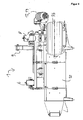
Figur 1- ein Ausführungsbeispiel der erfindungsgemäßen Vorrichtung in Seitenansicht mit dargestellten Wuchshilfen, wobei die
Seitenansicht gemäß Figur 1 bei Anordnen der Vorrichtung an eine Haltevorrichtung die der Haltevorrichtung abgewandte Seite zeigt; - Figur 1a
- eine Schnittdarstellung der Seitenansicht gemäß
Figur 1 , wobei die Schnittebene in der Rückansicht gemäßFigur 5 als Linie A gekennzeichnet ist; die Schnittebene steht senkrecht zur Zeichenebene gemäß Rückansicht inFigur 5 ; Figur 2- eine Seitenansicht der einer Haltevorrichtung zugewandten Seite;
Figur 3- eine Vorderansicht der Vorrichtung gemäß
Figur 1 mit dargestellten Wuchshilfen; - Figur 4
- eine Draufsicht von oben auf die
Vorrichtung gemäß Figur 1 ; - Figur 4a
- die Draufsicht gemäß
Figur 4 , wobei eine obere Abdeckung sowie ein oberes Einzugsrad entfernt wurden und Wuchshilfen dargestellt sind; - Figur 4b
- eine Schnittdarstellung gemäß Schnittlinie B in
Figur 3Figur 3 - Figur 5
- eine Ansicht von hinten auf die
Vorrichtung gemäß Figur 1 und - Figur 6
- eine perspektivische Darstellung der Vorrichtung gemäß
Figur 1
- FIG. 1
- an embodiment of the device according to the invention in side view with growth aids shown, wherein the side view according to
FIG. 1 when arranging the device to a holding device, the side facing away from the holding device; - FIG. 1a
- a sectional view of the side view according to
FIG. 1 , wherein the sectional plane in the rear view according toFIG. 5 marked as line A; the cutting plane is perpendicular to the drawing plane according to the rear view inFIG. 5 ; - FIG. 2
- a side view of a holding device facing side;
- FIG. 3
- a front view of the device according to
FIG. 1 with displayed growth aids; - FIG. 4
- a top view of the device according to
FIG. 1 ; - FIG. 4a
- the top view according to
FIG. 4 wherein an upper cover and an upper feed wheel have been removed and growth aids are shown; - FIG. 4b
- a sectional view along section line B in
FIG. 3 , where the cutting plane inFIG. 3 is perpendicular to the drawing plane; - FIG. 5
- a view from the rear of the device according to
FIG. 1 and - FIG. 6
- a perspective view of the device according to
FIG. 1 ,
Sämtliche Figuren zeigen eine Vorrichtung 1, zum Entfernen von Pflanzenteilen von mindestens einer länglichen, zugstabilen, biegeschlaffen Wuchshilfe, welche Vorrichtung ein Ausführungsbeispiel der erfindungsgemäßen Vorrichtung darstellt. Gleiche Bezugszeichen in den Figuren bezeichnen gleiche Elemente.All figures show a
Die Vorrichtung 1 ist zum Entfernen von Pflanzenteilen von beliebigen länglichen, zugstabilen, biegeschlaffen Wuchshilfen geeignet, wie beispielsweise von Seilen oder Drähten. Insbesondere ist die Vorrichtung 1 zum Einsatz im Weinbau geeignet, um Rebentriebe, welche von der Rebe abgeschnitten sind, jedoch noch an als Spalierdrähten ausgebildeten Wuchshilfen 2 anhaften, zu entfernen. In den
Die Vorrichtung 1 umfasst eine Wuchshilfeführung 3, welche als nach oben offener Führungskanal mit einem in etwa U-förmigen Querschnitt senkrecht zur Längsachse einer in der Wuchshilfeführung 3 liegenden Wuchshilfe 2 ausgebildet ist. Mittels der Wuchshilfeführung 3 werden die Wuchshilfen 2 insbesondere im Bereich einer Ablöseeinheit 4 der Vorrichtung 1 geführt. Dies ist insbesondere in den
Die Ablöseeinheit 4 umfasst eine Vielzahl von Ablöseelementen, von denen in
Die Vorrichtung 1 umfasst weiterhin eine Pflanzenführungseinheit 7, welche ein unteres Einzugsrad 7a und ein oberes Einzugsrad 7b umfasst.The
Die Einzugsräder 7a und 7b werden mittels eines zweiten Motors 8 gegensinnig angetrieben.The
Zur Verwendung der Vorrichtung 1 wird diese mittels einer seitlich angeordneten Halterung 9 an einer (nicht dargestellten) Haltevorrichtung angebracht, welche Haltevorrichtung wiederum an einem (nicht dargestellten) Traktor angebracht ist. Mittels der Haltevorrichtung kann die Vorrichtung 1 bezüglich der Höhe variiert werden sowie bezüglich der seitlichen Ausrichtung in Fahrtrichtung rechts vor dem Traktor.To use the
Zur Verwendung der Vorrichtung in einem Weinberg, beispielsweise mit Guyot-und/oder Kordonerziehung (wobei diese Beispiele nicht einschränkend sind), müssen entweder die betreffenden Spalierdrähte per Hand von den Haltepfosten entlang einer Weinrebenzeile entfernt werden oder mittels entsprechender Haltevorrichtungen, wie beispielsweise nach oben offenen Klemmhaken, an den Haltepfosten angebracht sein, so dass sie nach oben abgezogen werden können. An dem ersten und letzten Pfosten einer Weinrebenzeile sind die Spalierdrähte unlösbar angebracht.For use of the device in a vineyard, for example Guyot and / or cordon education (these examples are not limiting), either the trellis wires in question must be manually removed from the support posts along a row of vines or by means of appropriate holding devices, such as open topped Clamping hook, be attached to the support post so that they can be pulled off upwards. At the first and last post of a grapevine line the trellis wires are permanently attached.
Zu Beginn wird die Vorrichtung in eine Position nahe des ersten Pfosten gebracht und das obere Einzugsrad 7b sowie eine obere Abdeckung 10 (siehe
Die Wuchshilfen 2 verlaufen somit zwischen oberem Einzugsrad 7b und unterem Einzugsrad 7a (siehe
Anschließend wird mittels des Traktors die Vorrichtung 1 oberhalb der Pfosten der Weinrebenzeile entlanggefahren, so dass die Spalierdrähte 2 nach oben aus den Halterungen der Pfosten herausgezogen werden, sofern sie nicht bereits vorher aus entsprechenden Halterungen entfernt wurden. Der Traktor fährt nun entlang der Weinrebenzeile, so dass die Wuchshilfen 2 während dieser Bewegung durch die Vorrichtung 1 hindurchgeleitet werden. In den
An den Spalierdrähten anhaftende Pflanzenteile, insbesondere Rebentriebe werden somit zwischen den Einzugsrädern 7a und 7b hindurchgeführt und hierbei gegebenenfalls durch Zusammendrücken komprimiert und zu der Ablöseeinheit 4 (zusammen mit dem sich relativ zu der Vorrichtung 1 hindurchbewegenden Wuchshilfen 2) zugeführt.Plant parts adhering to the trellis wires, in particular vine shoots, are thus guided between the
Die als Schneidmesser ausgebildeten, rotierenden Ablöseelemente 4a, 4b lösen die Pflanzenteile von den Wuchshilfen 2 ab, durch Häckseln, Abschlagen und/oder Zerstückeln.The trained as a cutting blade, rotating detachment elements 4a, 4b solve the plant parts of the growth aids 2, by shredding, knocking and / or dismemberment.
Mittels der Wuchshilfeführung 3 wird gewährleistet, dass die Wuchshilfen 2 nicht mit den Ablöseelementen 4a, 4b der Ablöseeinheit 4 in Kontakt kommen und somit nicht durch diese beschädigt und insbesondere nicht durchtrennt werden.By means of the
Die Ablöseelemente 4a, 4b rotieren hierbei in der Ansicht in
Die abgelösten Pflanzenteile werden an einem Auslass 11 (siehe
Nachdem in einer Weinrebenzeile die Pflanzenteile von den Wuchshilfen 2 entfernt wurden, werden die Wuchshilfen 2 wieder in entsprechenden Halterungen an den Pfosten der Weinrebenzeile befestigt.After the plant parts have been removed from the growth aids 2 in a row of grapevines, the growth aids 2 are again secured in appropriate brackets to the posts of the grapevine line.
Ergänzend wird insbesondere zur Durchführung des Verfahrens auf
Die Pflanzenführungseinheit 7 ist aufgrund der Ausgestaltung mit dem unteren Einzugsrad 7a und dem oberen Einzugsrad 7b, welche parallele Drehachsen aufweisen, insbesondere zum Einzug von Pflanzenteilen, welche sich in etwa entlang der Wuchshilfen 2 erstrecken sowie von Pflanzenteilen, welche in der Vorderansicht gemäß
Bei von den Wuchshilfen 2 abstehenden Pflanzenteilen, die zumindest in Projektion auf eine senkrecht zu den Wuchshilfen 2 stehende Ebene eine in der Darstellung in
Die Vorrichtung 1 umfasst daher eine Pflanzenausrichteinheit 12. Die Pflanzenausrichteinheit 12 umfasst ein als Förderschnecke ausgebildetes Pflanzentransportmittel 13. Das Pflanzentransportmittel 13 stellt somit ein lineares Fördermittel dar. Die Pflanzenausrichteinheit 12 umfasst weiterhin eine Halterung, in der das Pflanzentransportmittel 13 drehbar gelagert ist sowie einen dritten Motor 14 zum Drehen der Förderschnecke des Pflanzentransportmittels der Pflanzenausrichteinheit 12 um die Achse der Förderschnecke.The
Die Pflanzenausrichteinheit 12 ist vor der Pflanzenführungseinheit 7 angeordnet, hinsichtlich der Relativbewegung der Wuchshilfeführung zu der Vorrichtung. An den Wuchshilfen 2 anhaftende Pflanzenteile gelangen somit zuerst in den Wirkungsbereich der Pflanzenausrichteinheit 12 und danach in den Wirkungsbereich der Pflanzenführungseinheit 7.The
Seitlich von den Wuchshilfen 2 abstehende Pflanzenteile können somit von dem Pflanzentransportmittel 13 erfasst und bewegt werden.Plant parts which project laterally from the growth aids 2 can thus be grasped and moved by the plant transport means 13.
Die Drehrichtung ist dabei derart gewählt, dass die von dem Pflanzentransportmittel 13 erfassten Pflanzenteile in
Die lineare Bewegung solcher Pflanzenteile mittels des Pflanzentransportmittels 13 bewirkt typischerweise ein Drehen dieses Pflanzenteils um die Längsachse der Wuchshilfen 2, das heißt eine Drehung gegen den Uhrzeigersinn in der Ansicht gemäß
Ausgehend von einer waagrechten Position des Pflanzenteils F wird dieser somit mittels des Pflanzentransportmittels 13 in Richtung einer senkrechten Position gemäß Darstellung in
Aufgrund der Relativbewegung der Wuchshilfe 2 zu der Vorrichtung 1 und des Anhaftens des Pflanzenteils F an der Wuchshilfe 2 wird das Pflanzenteil F weiterhin der Pflanzenführungseinheit 7 angenähert, trifft auf diese jedoch in senkrecht oder nahezu senkrechter Ausrichtung gemäß der Darstellung in
Das als Förderschnecke ausgebildete Pflanzentransportmittel 13 weist in axialer Erstreckung eine Länge von etwa 60 cm auf mit einer Schneckensteigung von etwa 12,5 cm und einem Durchmesser von etwa 12,5 cm.Trained as a screw conveyor plant transport means 13 has in the axial extent a length of about 60 cm with a screw pitch of about 12.5 cm and a diameter of about 12.5 cm.
Wesentlich ist, dass die Förderschnecke in Endbereichen (Bezugszeichen G und H in
In den genannten Bereichen G und H verringert sich der Durchmesser der Schnecke kontinuierlich zu dem jeweiligen Ende der Achse der Schnecke hin.In the aforementioned ranges G and H, the diameter of the screw decreases continuously toward the respective end of the axis of the screw.
Ohne eine solche Ausgestaltung besteht ein höheres Risiko, dass an den Endbereichen des als Förderschnecke ausgebildeten Transportmittels des Pflanzentransportmittels 13 sich Pflanzenteile um die Förderschnecke herumwickeln. Durch die konische Ausgestaltung wird ein solcher Fehler nahezu ausgeschlossen.Without such a configuration, there is a higher risk that at the end regions of the conveying means of the plant transporting means 13 designed as a conveying screw, parts of plants will wrap around the conveying screw. Due to the conical design such an error is almost impossible.
Der Teil des als Förderschnecke ausgebildeten Pflanzentransportmittels 13 wird mittels des dritten Motors 14 mit einer Umdrehungsgeschwindigkeit von etwa 220 U/min betrieben.The part of the conveying
Mit der erfindungsgemäßen Vorrichtung und dem erfindungsgemäßen Verfahren wird somit ein wesentliches Fehlerpotential beim maschinellen Entfernen von Pflanzenteilen von mindestens einer Wuchshilfe beseitigt, indem mittels der Pflanzenausrichteinheit von der Wuchshilfe abstehende Pflanzenteile in Richtung einer bevorzugten Einzugsorientierung der Pflanzenführungseinheit bewegt werden.Thus, with the device according to the invention and the method according to the invention, a substantial potential for error in the mechanical removal of plant parts from at least one growth aid is eliminated by moving plant parts projecting from the growth aid in the direction of a preferred intake orientation of the plant management unit by means of the plant alignment unit.
Claims (15)
dadurch gekennzeichnet,
dass die Vorrichtung (1) zusätzlich mindestens eine Pflanzenausrichteinheit mit mindestens einem motorisch angetriebenen Pflanzentransportmittel (13) umfasst,
welche Pflanzenausrichteinheit vor der Pflanzenführungseinheit (7) angeordnet ist, hinsichtlich der Relativbewegung der Wuchshilfeführung zu der Vorrichtung (1) und
welche Pflanzenausrichteinheit derart angeordnet und dazu ausgebildet ist, mittels des Pflanzentransportmittels (13) von der Wuchshilfe (2) abstehende Pflanzenteile in Richtung einer bevorzugten Einzugsorientierung der Pflanzenführungseinheit (7) zu bewegen.Device (1) for removing parts of plants from at least one elongated, tensile stable, limp growth aid (2) during movement of the device (1) along the growth aid (2), in particular for removing vine shoots of at least one trellis wire
characterized,
that the device (1) additionally at least one Pflanzenausrichteinheit with at least one motor-driven plant transport means (13),
which plant alignment unit is arranged in front of the plant guidance unit (7) with regard to the relative movement of the growth aid guide to the device (1) and
which plant alignment unit is arranged and configured to move plant parts projecting from the growth aid (2) by means of the plant transport means (13) in the direction of a preferred intake orientation of the plant management unit (7).
dadurch gekennzeichnet,
dass die Pflanzenausrichteinheit derart angeordnet und dazu ausgebildet ist, mittels des Pflanzentransportmittels (13) von der Wuchshilfe (2) abstehende Pflanzenteile zu drehen, insbesondere,
dass Drehung um eine Drehachse erfolgt, welche Drehachse in etwa mit der Längsachse der Wuchshilfe (2) im Bereich der Pflanzenausrichteinheit übereinstimmt.Device (1) according to claim 1,
characterized,
in that the plant alignment unit is arranged and designed to rotate plant parts projecting from the growth aid (2) by means of the plant transport means (13), in particular,
that rotation takes place about an axis of rotation, which axis of rotation approximately with the longitudinal axis of the growth aid (2) in the region of the plant alignment unit matches.
dadurch gekennzeichnet,
dass das Pflanzentransportmittel (13) als lineares Fördermittel ausgebildet ist.Device (1) according to one of the preceding claims,
characterized,
in that the plant transporting means (13) is designed as a linear conveying means.
dadurch gekennzeichnet,
dass das Pflanzentransportmittel (13) als Förderschnecke ausgebildet ist, insbesondere,
dass die Förderschnecke an einem Ende, bevorzugt an beiden Enden, konisch zulaufend ausgebildet ist.Device (1) according to claim 3,
characterized,
that the plant transport means (13) is designed as a screw conveyor, in particular,
that the screw conveyor is formed at one end, preferably at both ends, tapered.
dadurch gekennzeichnet,
dass die Pflanzenausrichteinheit einen motorischen Antrieb zum Drehen der Förderschnecke umfasst, insbesondere,
dass der motorische Antrieb ausgebildet ist zum Drehen der Förderschnecke mit einer Umdrehungsgeschwindigkeit im Bereich 100 U/min bis 400 U/min, bevorzugt im Bereich 200 U/min bis 250 U/min.Device (1) according to claim 4,
characterized,
in that the plant alignment unit comprises a motor drive for rotating the conveyor screw, in particular,
in that the motor drive is designed to rotate the screw conveyor at a speed of rotation in the range from 100 rpm to 400 rpm, preferably in the range from 200 rpm to 250 rpm.
dadurch gekennzeichnet,
dass die Förderschnecke einen Durchmesser im Bereich 3 cm bis 25 cm, bevorzugt im Bereich 5 cm bis 22 cm, weiter bevorzugt im Bereich 9 cm bis 20 cm aufweist und/oder
dass die Förderschnecke eine Ganghöhe im Bereich 10 cm bis 15 cm, bevorzugt etwa 12,5 cm aufweist.Device (1) according to one of claims 4 to 5,
characterized,
that the screw conveyor has a diameter in the range 3 cm to 25 cm, preferably in the range 5 cm to 22 cm, more preferably in the range 9 cm to 20 cm and / or
that the screw conveyor has a pitch in the range 10 cm to 15 cm, preferably about 12.5 cm.
dadurch gekennzeichnet,
dass das lineare Fördermittel mit Förderrichtung in einem vorgegebenen Winkel zu der bevorzugten Einzugsorientierung der Pflanzenführungseinheit (7) angeordnet ist, vorzugsweise in einem Winkel im Bereich 3° bis 20°, bevorzugt im Bereich 5° bis 15°, weiter bevorzugt etwa 9°.Device (1) according to one of claims 3 to 6,
characterized,
that the linear conveying means is arranged with conveying direction at a predetermined angle to the preferred feed orientation of the plant guide unit (7), preferably at an angle in the range 3 ° to 20 °, preferably in the range 5 ° to 15 °, more preferably about 9 °.
dadurch gekennzeichnet,
dass der Winkel zwischen Förderrichtung des linearen Fördermittels und der bevorzugten Einzugsorientierung der Pflanzenführungseinheit (7) durch einen Benutzer wahlweise vorgebbar ist.Device (1) according to one of claims 3 to 7,
characterized,
in that the angle between the conveying direction of the linear conveying means and the preferred feed orientation of the plant guiding unit (7) can be optionally predetermined by a user.
dadurch gekennzeichnet,
dass das lineare Fördermittel derart ausgebildet ist, dass bei Betrieb von dem Fördermittel erfasste Pflanzenteilbereiche nach oben bewegt werden.Device (1) according to one of claims 3 to 8,
characterized,
in that the linear conveying means is designed such that, during operation, plant subareas captured by the conveying means are moved upwards.
dadurch gekennzeichnet,
dass der lineare Förderweg des Fördermittels eine Länge im Bereich von 0,3 m bis 1,2 m, bevorzugt im Bereich von 0,5 m bis 0,7 m aufweist.Device (1) according to one of claims 3 to 9,
characterized,
that the linear conveying path of the conveying means has a length in the range of 0.3 m to 1.2 m, preferably in the range of 0.5 m to 0.7 m.
dadurch gekennzeichnet,
dass die Pflanzenführungseinheit (7) ein Einzugsrad (7b) umfasst, mit einer bevorzugten Einzugsrichtung in etwa senkrecht zu der Drehachse des Einzugsrades.Device (1) according to one of the preceding claims,
characterized,
that the plant guiding unit (7) comprises a deshingler wheel (7b), with a preferred feed direction approximately perpendicular to the axis of rotation of the feed wheel.
dadurch gekennzeichnet,
dass das Pflanzentransportmittel (13) mit einem Abstand senkrecht zu einer die Pflanzenführungseinheit (7) durchlaufenden Wuchshilfe (2) kleiner 50 cm, bevorzugt im Bereich zwischen 5 cm und 30 cm, weiter bevorzugt im Bereich zwischen 10 cm und 20 cm zu der Pflanzenführungseinheit (7) angeordnet ist.Device (1) according to one of the preceding claims,
characterized,
in that the plant transporting means (13) extends at a distance perpendicular to a plant guide unit (7) through the growth aid (2) smaller than 50 cm, preferably in the range between 5 cm and 30 cm, more preferably in the range between 10 cm and 20 cm to the plant management unit (2). 7) is arranged.
dadurch gekennzeichnet,
dass das Pflanzentransportmittel (13) mit einem Abstand in Richtung der Längserstreckung einer die Pflanzenführungseinheit (7) durchlaufenden Wuchshilfe (2) kleiner 50 cm, bevorzugt im Bereich zwischen 5 cm und 30 cm, weiter bevorzugt im Bereich zwischen 10 cm und 20 cm zu der
Pflanzenführungseinheit (7) angeordnet ist.Device (1) according to one of the preceding claims,
characterized,
in that the plant transporting means (13) extends at a distance in the direction of the longitudinal extent of a growth aid (2) smaller than 50 cm, preferably in the range between 5 cm and 30 cm, more preferably in the range between 10 cm and 20 cm, passing through the plant guiding unit (7)
Plant guide unit (7) is arranged.
folgende Verfahrensschritte umfassend:
dass vor dem Komprimieren und/oder Zuführen der Pflanzenteile mittels der Pflanzenführungseinheit (7) von der Wuchshilfe (2) abstehende Pflanzenteile mittels eines motorisch angetriebenen Pflanzentransportmittels (13) in Richtung einer bevorzugten Einzugsorientierung der Pflanzenführungseinheit (7) bewegt werden.Method for removing parts of plants from at least one elongate, stable, non-rigid growth aid (2) by means of a device (1) during movement of the device (1) along the growth aid (2), in particular for removal of vine shoots from at least one trellis wire,
comprising the following method steps:
that prior to compressing and / or feeding the plant parts by means of the plant guide unit (7) from the growth aid (2) projecting plant parts by means of a motor-driven plant transport means (13) in the direction of a preferred feed orientation of the plant guide unit (7) are moved.
dadurch gekennzeichnet,
dass mittels des Pflanzentransportmittels (13) von der Wuchshilfe (2) abstehende Pflanzenteile gedreht werden, insbesondere,
dass die Drehachse in etwa mit der Längsachse der Wuchshilfe (2) im Bereich der Pflanzenausrichteinheit übereinstimmt.Method according to claim 14,
characterized,
in that, by means of the plant transporting means (13), plant parts projecting from the growth aid (2) are turned, in particular,
that the rotation axis coincides approximately with the longitudinal axis of the growth aid (2) in the area of Pflanzenausrichteinheit.
Priority Applications (1)
| Application Number | Priority Date | Filing Date | Title |
|---|---|---|---|
| EP11001168A EP2486786A1 (en) | 2011-02-14 | 2011-02-14 | Device and method for removing plant parts from a support line |
Applications Claiming Priority (1)
| Application Number | Priority Date | Filing Date | Title |
|---|---|---|---|
| EP11001168A EP2486786A1 (en) | 2011-02-14 | 2011-02-14 | Device and method for removing plant parts from a support line |
Publications (1)
| Publication Number | Publication Date |
|---|---|
| EP2486786A1 true EP2486786A1 (en) | 2012-08-15 |
Family
ID=44242679
Family Applications (1)
| Application Number | Title | Priority Date | Filing Date |
|---|---|---|---|
| EP11001168A Withdrawn EP2486786A1 (en) | 2011-02-14 | 2011-02-14 | Device and method for removing plant parts from a support line |
Country Status (1)
| Country | Link |
|---|---|
| EP (1) | EP2486786A1 (en) |
Cited By (2)
| Publication number | Priority date | Publication date | Assignee | Title |
|---|---|---|---|---|
| DE102013219651B3 (en) * | 2013-09-27 | 2014-11-20 | ERO-Gerätebau GmbH | Device for removing parts of plants from a growth aid |
| EP2823704A2 (en) | 2013-07-11 | 2015-01-14 | ERO-GERÄTEBAU GmbH | Device and method for removing plant pieces |
Citations (4)
| Publication number | Priority date | Publication date | Assignee | Title |
|---|---|---|---|---|
| FR2733118A1 (en) * | 1995-04-21 | 1996-10-25 | Lacoste Philippe | Machine for removing vine shoots |
| WO1997036473A2 (en) * | 1996-04-01 | 1997-10-09 | Fontan Gerard | Pruning machine with a lifting and separating function |
| DE102004031088A1 (en) | 2004-06-28 | 2006-01-19 | Manfred Bermes | Method of removing branches from a trellis and apparatus therefor |
| WO2009051498A2 (en) | 2007-10-19 | 2009-04-23 | Honeypot Holdings Limited | Method and apparatus for stripping material from a line |
-
2011
- 2011-02-14 EP EP11001168A patent/EP2486786A1/en not_active Withdrawn
Patent Citations (4)
| Publication number | Priority date | Publication date | Assignee | Title |
|---|---|---|---|---|
| FR2733118A1 (en) * | 1995-04-21 | 1996-10-25 | Lacoste Philippe | Machine for removing vine shoots |
| WO1997036473A2 (en) * | 1996-04-01 | 1997-10-09 | Fontan Gerard | Pruning machine with a lifting and separating function |
| DE102004031088A1 (en) | 2004-06-28 | 2006-01-19 | Manfred Bermes | Method of removing branches from a trellis and apparatus therefor |
| WO2009051498A2 (en) | 2007-10-19 | 2009-04-23 | Honeypot Holdings Limited | Method and apparatus for stripping material from a line |
Cited By (4)
| Publication number | Priority date | Publication date | Assignee | Title |
|---|---|---|---|---|
| EP2823704A2 (en) | 2013-07-11 | 2015-01-14 | ERO-GERÄTEBAU GmbH | Device and method for removing plant pieces |
| DE102013213623A1 (en) | 2013-07-11 | 2015-01-15 | ERO-Gerätebau GmbH | Device and method for removing parts of plants |
| DE102013219651B3 (en) * | 2013-09-27 | 2014-11-20 | ERO-Gerätebau GmbH | Device for removing parts of plants from a growth aid |
| EP2853149A1 (en) | 2013-09-27 | 2015-04-01 | ERO-GERÄTEBAU GmbH | Device for stripping shoots or plants from trellis |
Similar Documents
| Publication | Publication Date | Title |
|---|---|---|
| WO1997017751A1 (en) | Insulation stripping device | |
| EP2512256B1 (en) | Device and method for removing a poultry breast gristle | |
| EP2486787B1 (en) | Device and method for removing plant parts from a climbing support | |
| EP2853149B1 (en) | Device for stripping shoots or plants from trellis | |
| EP2823704B1 (en) | Device and method for removing plant pieces | |
| DD213583B5 (en) | A silage cutter | |
| EP2486786A1 (en) | Device and method for removing plant parts from a support line | |
| DE102004031088B4 (en) | Method of removing branches from a trellis and apparatus therefor | |
| DE102005003204B3 (en) | Cross-cutting device for material web has two pressing devices at minimum spacing round cylinder, permitting cutter unhindered passage between them | |
| DE102020116575B4 (en) | Device and method for cutting a cardboard blank at least laterally | |
| EP2486788A1 (en) | Device and method for removing plant parts from a climbing support | |
| EP2486789A1 (en) | Device and method for removing plant parts from a climbing support | |
| DE102007048757B4 (en) | Device and method for defoliation, in particular of grapevines | |
| DE9116440U1 (en) | Device for trimming plants in pots, especially azaleas | |
| EP0815982B1 (en) | Wire guiding device for the treatment of wire ends | |
| EP2884833B1 (en) | Device and method for removing branches, in particular canes, from an espalier | |
| EP2986102B1 (en) | Device for extracting silage | |
| EP2457443A1 (en) | Method for mechanical twisting of dough strips | |
| EP2599381A1 (en) | Greenhouse table and method for producing plants in a greenhouse comprising a corresponding greenhouse table | |
| DE102007049344B4 (en) | Device for defoliation, in particular of grapevines | |
| DE102007010550A1 (en) | Apparatus and method for peeling elongated vegetables | |
| EP2407020A2 (en) | Cutting assembly for an agricultural harvester | |
| EP3651563B1 (en) | Device for preventing an accumulation of leaves and stems and associated harvesting machine | |
| AT505654B1 (en) | METHOD AND DEVICE FOR EFFECTING GEARING GEARS | |
| DE102008030648A1 (en) | For cutting a wood trunk, one end is raised partially at an angle with an intermittent forward movement synchronized with the cutter |
Legal Events
| Date | Code | Title | Description |
|---|---|---|---|
| PUAI | Public reference made under article 153(3) epc to a published international application that has entered the european phase |
Free format text: ORIGINAL CODE: 0009012 |
|
| AK | Designated contracting states |
Kind code of ref document: A1 Designated state(s): AL AT BE BG CH CY CZ DE DK EE ES FI FR GB GR HR HU IE IS IT LI LT LU LV MC MK MT NL NO PL PT RO RS SE SI SK SM TR |
|
| AX | Request for extension of the european patent |
Extension state: BA ME |
|
| STAA | Information on the status of an ep patent application or granted ep patent |
Free format text: STATUS: THE APPLICATION IS DEEMED TO BE WITHDRAWN |
|
| 18D | Application deemed to be withdrawn |
Effective date: 20130216 |