EP2486787B1 - Device and method for removing plant parts from a climbing support - Google Patents
Device and method for removing plant parts from a climbing support Download PDFInfo
- Publication number
- EP2486787B1 EP2486787B1 EP11001169.9A EP11001169A EP2486787B1 EP 2486787 B1 EP2486787 B1 EP 2486787B1 EP 11001169 A EP11001169 A EP 11001169A EP 2486787 B1 EP2486787 B1 EP 2486787B1
- Authority
- EP
- European Patent Office
- Prior art keywords
- intake
- elements
- plant
- wheel
- shaft
- Prior art date
- Legal status (The legal status is an assumption and is not a legal conclusion. Google has not performed a legal analysis and makes no representation as to the accuracy of the status listed.)
- Active
Links
- 238000000034 method Methods 0.000 title description 10
- 230000009194 climbing Effects 0.000 title 1
- 230000033001 locomotion Effects 0.000 claims description 36
- 230000006835 compression Effects 0.000 claims description 21
- 238000007906 compression Methods 0.000 claims description 21
- 230000007423 decrease Effects 0.000 claims description 3
- 241000196324 Embryophyta Species 0.000 description 246
- 238000011835 investigation Methods 0.000 description 14
- 238000013461 design Methods 0.000 description 8
- 230000015572 biosynthetic process Effects 0.000 description 7
- 238000005755 formation reaction Methods 0.000 description 7
- 230000006378 damage Effects 0.000 description 6
- 235000014787 Vitis vinifera Nutrition 0.000 description 5
- 240000006365 Vitis vinifera Species 0.000 description 5
- 238000009369 viticulture Methods 0.000 description 5
- 230000002829 reductive effect Effects 0.000 description 4
- 230000003247 decreasing effect Effects 0.000 description 3
- 238000001514 detection method Methods 0.000 description 3
- 238000006073 displacement reaction Methods 0.000 description 3
- 230000000694 effects Effects 0.000 description 3
- 238000009825 accumulation Methods 0.000 description 2
- 239000003795 chemical substances by application Substances 0.000 description 2
- 230000001788 irregular Effects 0.000 description 2
- 238000012423 maintenance Methods 0.000 description 2
- 239000002184 metal Substances 0.000 description 2
- 230000000149 penetrating effect Effects 0.000 description 2
- 238000000926 separation method Methods 0.000 description 2
- 208000027418 Wounds and injury Diseases 0.000 description 1
- 230000001464 adherent effect Effects 0.000 description 1
- 230000002411 adverse Effects 0.000 description 1
- 238000011161 development Methods 0.000 description 1
- 208000014674 injury Diseases 0.000 description 1
- 230000000670 limiting effect Effects 0.000 description 1
- 238000003754 machining Methods 0.000 description 1
- 238000005457 optimization Methods 0.000 description 1
- 230000036961 partial effect Effects 0.000 description 1
- 238000013138 pruning Methods 0.000 description 1
- 238000012549 training Methods 0.000 description 1
- 239000006163 transport media Substances 0.000 description 1
- 238000004804 winding Methods 0.000 description 1
Images


Classifications
-
- A—HUMAN NECESSITIES
- A01—AGRICULTURE; FORESTRY; ANIMAL HUSBANDRY; HUNTING; TRAPPING; FISHING
- A01G—HORTICULTURE; CULTIVATION OF VEGETABLES, FLOWERS, RICE, FRUIT, VINES, HOPS OR SEAWEED; FORESTRY; WATERING
- A01G17/00—Cultivation of hops, vines, fruit trees, or like trees
- A01G17/02—Cultivation of hops or vines
-
- A—HUMAN NECESSITIES
- A01—AGRICULTURE; FORESTRY; ANIMAL HUSBANDRY; HUNTING; TRAPPING; FISHING
- A01G—HORTICULTURE; CULTIVATION OF VEGETABLES, FLOWERS, RICE, FRUIT, VINES, HOPS OR SEAWEED; FORESTRY; WATERING
- A01G3/00—Cutting implements specially adapted for horticultural purposes; Delimbing standing trees
- A01G3/04—Apparatus for trimming hedges, e.g. hedge shears
- A01G3/0408—Apparatus for trimming hedges, e.g. hedge shears specially adapted for trellis work, e.g. machines for pruning vine or the like
Definitions
- the invention relates to a device for removing parts of plants from at least one elongated, karstabilen, limp growth aid during movement of the device along the growth aid according to the preamble of claim 1.
- pliable growth aids such as ropes or wires are known to support the plants and / or to influence the growth of the plants.
- pliable growth aids such as ropes or wires
- the use of trellis wires is known, for example in Guyot and also in cordon education.
- WO 2009/051498 A2 an apparatus and a method for removing parts of plants from a growth aid is known, wherein adhering to the growth aid plant parts are compressed by means of a plant supply unit and / or supplied to a detaching unit.
- the detaching unit comprises at least one detaching element, such as a rotating cutting blade, by means of which the plant parts are at least partially detached from the growth aid.
- the growth aid is guided during the machining process by means of a growth aid guide in order to avoid in particular damage to the growth aid guide by the detachment element.
- the plant parts can grow irregularly and in particular after cutting off the main plant in different directions and in different lengths of the growth aid can stand so high demands on the method and device for removing consist of all the forms of plant parts.
- the plant parts can by wrapping and / or ramifications have a stable connection with the growth aid, which is difficult to solve.
- the present invention is therefore based on the object to improve the prior art devices and methods for removing parts of plants from a growth aid and to reduce the susceptibility to errors and the resulting interruptions during operation.
- the device according to the invention for removing parts of plants from at least one elongated, tensile stable, non-limp growth aid during a movement of the device along the growth aid comprises a growth aid guide for guiding the growth aid during the movement of the device along the growth aid. Furthermore, the device comprises a detachment unit. The apparatus further comprises a plant guide unit for compressing and / or feeding the plant parts adhering to the growth aid to the detachment unit.
- the detachment unit comprises at least one detachment element, which detachment element is movably arranged on the device in such a way that, when operated by movement of the detachment element, plant parts are at least partially detachable from the growth aid.
- the plant management unit comprises at least one rotatably arranged feed wheel for feeding in and / or for compressing the plant parts.
- the plant management unit comprises a plurality of intake elements.
- Each of the plurality of intake elements is movable and a real or imaginary lateral surface of the Einzugsrades penetrating arranged such that upon rotation of the Einzugsrades the intake element in a forward position with respect to the direction of movement of the device further protrudes from the lateral surface than in a rearward position.
- the lateral surface of the feed wheel substantially closed with recesses for the intake elements. In this case, one can speak of a real lateral surface. It is also within the scope of the invention that the lateral surface of the feed wheel has one or more recesses, for example formed by individual elements such as rods along the circumference of the Einzugsrades. In such cases, the lateral surface is the smallest envelope of the feed wheel and thus represents an imaginary lateral surface.
- each of the plurality of catchment elements in a forward position with respect to the direction of movement of the device protrudes further from the lateral surface than in a position to the rear.
- the feeder elements further protrude from the lateral surface and thus an efficient detection is ensured and in the rear area of the feed wheel, in which the Plant parts are already compressed or made suitable for feeding to the detaching unit, the catchment elements protrude less far out of the lateral surface, so that an adverse effect on the plant parts and the growth aid is excluded as described above.
- the ratio between the operating and maintenance period of the device according to the invention is significantly improved and thus increases the efficiency.
- the feed wheel and the plurality of intake elements are designed such that, in the forward position, the intake elements protrude from the outer surface by a length which is greater by at least a factor of two than in FIG Position to the rear, preferably by at least a factor of 3, more preferably by at least a factor of 5.
- each of the plurality of intake elements is rotatably arranged with a rotation axis perpendicular to a longitudinal extent of the intake element.
- all catchment elements are arranged rotatably about a common axis of rotation, wherein preferably the plurality of catchment elements offset in the axial direction of their common axis of rotation, preferably arranged side by side.
- the above-mentioned guidance of the intake elements by the intake wheel is preferably formed in that the lateral surface of the Einzugsrades has recesses through which extend the intake elements, so that a rotational movement of the wheel is transmitted to the respective intake element by the edge of the recess.
- a structurally simple and robust embodiment in particular, the above-described different lengths of the protrusion of the feeder elements is guaranteed depending on the position of the feeder elements, results in a preferred embodiment in which the axis of rotation of each of the plurality of Einzugss instituten parallel to the axis of rotation of Einzugsrades is, wherein preferably the axis of rotation of each of the plurality of catchment elements is spaced from the axis of rotation of the Einzugsrades.
- the axis of rotation of each of the plurality of catch elements is preferably arranged at least in the direction of movement of the device forwardly spaced from the axis of rotation of the Einzugsrades.
- each of the plurality of intake elements is advantageous to arrange the axis of rotation of each of the plurality of intake elements at least in a direction away from a compression region of the Einzugsrades direction spaced from the axis of rotation of the Einzugsrades, in particular to combine both aforementioned spacings.
- the plant management unit of the device according to the invention has a counter element to the feed wheel, so that between the feed wheel and counter element a compression takes place at least irregularly from the plant growing parts protruding from the growth aid.
- the plant management unit is designed such that each of the plurality of intake elements does not touch the counter element regardless of the position of the intake element. In order nevertheless to ensure a sufficiently broad protrusion of the catchment elements in the direction of movement of the device in front region of the feed wheel, it is advantageous to provide in addition to the aforementioned spacing to the front and a spacing in the opposite direction of the position of the compression region.
- the feeder elements are arranged in groups in the axial direction of their axis of rotation. This means that in axial projection, the intake elements of a group always have the same position.
- groups of two i. H. to group the feeder elements in pairs in the axial direction of their axis of rotation.
- the device according to the invention such that the growth aid in operation between the intake elements of a Group runs so that at least one catchment element right and a catchment element left of the growth aid ensures the entry of the plants.
- the groups have an increasing distance of the feeder elements in the axial direction. This means that when viewing a rotating feed wheel from the front, the distance between two successive feeder elements is reduced to jump back to the maximum distance after a complete rotation. In this view, this results in a V-shaped merging of the intake elements when viewing a rotating feed wheel from the front, which can already exert a compression function on the plant parts.
- the growth aid in which in addition the growth aid is guided between the intake elements of a group advantageous that centered by the above each approaching the feeder elements in the axial direction, the growth aid with each complete rotation of the feed wheel in the central region of the feeder elements with the smallest distance becomes. As a result, a slipping out or a displacement of the growth aid can thus be corrected perpendicular to the longitudinal extent of the growth aid.
- the plant guide unit of the device according to the invention preferably has a counter element to the feed wheel, which is arranged to form a compression region for the plant parts between the feed wheel and the counter element.
- the counter element in a structurally simple manner, for example as a surface, in particular as a sheet.
- the counter-element form as Gegeneinzugsrad.
- the Schmidteinzugsrad preferably has a parallel to the feed wheel axis of rotation and is preferably driven in opposite directions to the feed wheel.
- the catchment elements in the compression area come close to the counter-engagement wheel, but do not touch it.
- the plurality of intake elements have a distance in the range of 1 cm to 20 cm, preferably in the range of 1 cm to 10 cm, more preferably in the range of 1 cm to 5 cm to the counter element in the compression region.
- the counter element as Gegeneinzugsrad it is advantageous to form the Gegeneinzugsrad barrel-shaped with a decreasing in the axial direction outward radius and the axial direction more spaced catch elements with a greater length than the less widely spaced catchment elements each one group.
- the decreasing outwardly radius of Gegeneinzugsrades is compensated by the greater length of the outer intake elements, so that there is approximately a constant distance between intake element and surface of Schmidteinzugsrades, regardless of the distance between the intake elements.
- the plurality of intake elements at the opposite end of the direction of the device compression end of the device by less than 5 cm, preferably by less than 3 cm, more preferably not protrude from the lateral surface of the Einzugsrades.
- the growth aid in the compression region of the feed wheel in the axial direction is approximately in the middle.
- the feed wheel has an approximately centrally in the axial direction guide for a growth aid.
- Such a guide may be formed for example by a wedge or U-shaped incision.
- the feed wheel is formed with an approximately trough-shaped cross-section parallel to the axis of rotation and preferably in Starting from the middle of the axial direction each has an outwardly increasing radius.
- the feed wheel is preferably rim-shaped.
- each of the plurality of catchment elements is detachably arranged on a rotation axis.
- each of the plurality of catchment elements is detachably and rotatably arranged on a rotation axis.
- each of the plurality of intake elements at least partially surrounds a sleeve, so that when the sleeve is arranged in the Umgreifungs Scheme of the feeder element, the feeder element is not detachable from the sleeve and thus not from the axis of rotation, but upon displacement of the sleeve, so that the Umgreifungs Scheme directly abuts the axis of rotation, a release of the catchment element is possible.
- the Umgreifungs Scheme of the intake element thus preferably has an opening which is smaller than the outer radius of the sleeve, but larger than the outer radius of the axis of rotation.
- a structurally simple embodiment results in the advantageous embodiment, that at each of the plurality of retraction elements, a C-shaped profile for gripping the sleeve is formed.
- each of the plurality of catchment elements has rounded edges on the side facing in the direction of rotation.
- each of the plurality of intake elements it is advantageous for each of the plurality of intake elements to have an approximately rectangular cross-section perpendicular to the longitudinal extent, with edges rounded on the side pointing in the direction of rotation.
- the catchment elements are designed and arranged such that has the narrow side of the rectangular cross section in the radial direction and the longer side of the rectangular cross section in the axial direction. As a result, an efficient intervention is ensured due to the narrow side acting on the plant parts and at the same time ensures high stability due to the standing perpendicular to the axis of rotation long side of the rectangular cross-section.
- the intake elements preferably have an approximately rectangular cross-section with a height in the range 1 cm to 5 cm, preferably 1 cm to 3 cm, more preferably about 2 cm and a width in the range 0.3 cm to 2 cm, preferably 0.3 cm to 1 cm, more preferably about 0.6 cm.
- the rounded edges are preferably formed with a radius of about 0.5 mm.
- the intake elements or the groups of intake elements are approximately evenly distributed in the circumferential direction of the feed wheel.
- the plant management unit has between 5 and 15 intake elements or groups of intake elements, preferably between 6 and 10 intake elements or groups of intake elements.
- the catchment elements preferably have a length in the range 10 cm to 30 cm, preferably 15 cm to 25 cm.
- the feeder elements are preferably made of metal and in particular preferably galvanized. This ensures a long shelf life.
- the device according to the invention is particularly suitable for removing vine shoots of at least one trellis wire in viticulture.
- vine shoots which are indeed cut from the vine, but still adhere to the trellis wire, as typically vine shoots after the manual pruning.
- the device according to the invention is also applicable to other plant educations in which plant parts adhere to an elongated, karstabilen, limp growth aid, in particular already separated from the main plant parts of plants.
- the device according to the invention preferably comprises a holding device, by means of which the device is arranged on a vehicle such as a tractor.
- the holding device is designed such that the device for removal with respect to the height and the lateral distance to the vehicle can be selectively moved.
- Such holding devices are already known in tractors.
- the device according to the invention basically according to the device according to WO 2009/051498 A2 or a preferred embodiment thereof.
- Full reference is made to this prior art and it is expressly incorporated by reference in its entirety.
- the development of the previously known device consists in particular in the formation of the plant management unit as described above.
- the device additionally comprises at least one plant straightening unit in an advantageous embodiment, with at least one motor-driven plant transport means , which plant alignment unit the plant management unit is arranged, with respect to the relative movement of the growth aid guide to the device and which plant alignment arranged and designed to move by means of the plant transport from the growth aid projecting plant parts in the direction of a preferred feed orientation of the plant management unit.
- the plant alignment unit is preferably arranged and designed to move plant parts projecting from the growth aid by means of the plant transporting means in the direction of a preferred intake orientation of the plant management unit.
- the plant alignment unit is arranged and designed to rotate by means of the plant transport means from the growth aid projecting plant parts.
- the rotation takes place about an axis of rotation, which axis of rotation coincides approximately with the longitudinal axis of the growth aid in the region of the plant alignment unit.
- the plant transport agent is preferably designed as a linear conveyor. This results in a robust and cost-effective design of the conveyor and at the same time an efficient and error-prone orientation of the growing aid projecting plant parts in the direction of a preferred feed orientation of the plant supply unit.
- the formation of the plant transport means is a screw conveyor.
- Investigations by the applicant have shown that a screw conveyor is robust and at the same time inexpensively formed, for example, by the known in metal screw conveyors, which are rotated by means of a motor, such as a hydraulic motor or an electric motor to the axis of symmetry of the worm shaft.
- a linear transport of the portion of the plant part, which comes into contact with the screw is achieved in a simple manner. Due to the linear transport a rotation of the plant part is achieved by the growth aid in a simple manner due to the adherence of the plant part of the growth aid.
- the formation of the plant transport means as screw conveyor also has the advantage that in case of wrapping the screw conveyor by plants or other objects such can be corrected manually in a short time and beyond there is only a small risk of injury, even if a user in the company the rotating screw conveyor should come into contact.
- the screw conveyor is preferably formed at one end, preferably at both ends, tapered. This means that in the axial direction to the respective end, the pitch of the screw is reduced. Applicant's investigations have shown that such conical feeding virtually eliminates errors due to wrapping of the screw by plant parts.
- the plant alignment unit preferably comprises a motor drive for rotating the conveyor screw. Investigations by the Applicant have shown that, in particular, it is advantageous to rotate the screw conveyor at a speed of rotation in the range from 100 rpm to 400 rpm, preferably in the range from 200 rpm to 250 rpm.
- the conveyor screw has a diameter in the range 3 cm to 25 cm, preferably in the range 5 cm to 22 cm, more preferably in the range 9 cm to 20 cm.
- the screw conveyor has a pitch in the range 10 cm to 15 cm, preferably about 12.5 cm.
- the plant transport means designed as a linear conveyor is arranged with conveying direction at a predetermined angle to the preferred intake orientation of the plant management unit.
- Investigations by the applicant have shown that in particular an arrangement at an angle in the range of 3 ° to 20 °, preferably in the range of 5 ° to 15 °, more preferably about 9 ° is advantageous.
- By the aforementioned preferred angle of attack in plan view from the front of the device according to the invention is achieved that upon rotation of the plant parts to the growth aid they are rotated as far as possible in the direction of preferred feed orientation by the linear conveyor.
- the angle between the conveying direction of the linear conveyor and the preferred feed orientation of the plant management unit by a user is optionally predetermined, in particular that the linear conveyor is pivotally mounted and optionally detectable on the device. This allows the user to optionally optimize the aforementioned angle.
- the conveying path of the conveying means preferably has a length in the range from 0.3 m to 1.2 m, preferably in the range from 0.5 m to 0.7 m. Investigations by the Applicant have shown that larger lengths considerably complicate the handling of the device and smaller lengths do not allow sufficient movement of the plant parts in the direction of the preferred orientation of feed.
- the distance of the plant alignment unit perpendicular to a plant guide unit passing through growth aid is preferably ⁇ 50 cm and is preferably in the range between 5 cm and 30 cm, more preferably in the range between 10 cm and 20 cm to the growth aid. This ensures that, on the one hand, no balls or bales are produced with the aforementioned negative consequences and, on the other hand, plant rows, which are easily pulled in by the plant management unit, are not unnecessarily loaded by the plant alignment unit.
- the plant transport medium is preferably arranged at a distance ⁇ 50 cm, preferably in the range between 5 cm and 30 cm, more preferably in the range between 10 cm and 20 cm from the plant management unit.
- the detachment unit and the auxiliary power guide are configured cooperatively such that, in operation, the detachment element has a spacing in the axial direction in the range of 5 mm to 30 mm, preferably in the range of 10 mm to 20 mm, more preferably approximately 15 mm, to the growth aid ,
- the plant management unit is to be formed as described above.
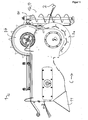
- the device 1 is suitable for removing parts of plants from any elongated, karstabilen, pliable growth aids, such as ropes or wires.
- the device 1 is suitable for use in viticulture to vine shoots, which are cut off from the vine, but still adhere to trained as Trellierdrähten growth aids 2 to remove.
- FIGS. 1 . 1a . 3 . 4a and 5 For better understanding in each case three growth aids 2 are shown.
- the device 1 comprises a growth aid guide 3 which is designed as an upwardly open guide channel with an approximately U-shaped cross-section perpendicular to the longitudinal axis of a growth aid 2 lying in the growth aid guide.
- the growth aid guide 3 By means of the growth aid guide 3, the growth aids 2 are guided in particular in the region of a detaching unit 4 of the device 1. This is especially true in the FIGS. 1a . 4a and 3 seen.
- the detaching unit 4 comprises a plurality of detachment elements, of which in FIG. 1a .
- FIG. 4a and 4b two detachment elements 4a and 4b are exemplified.
- the release elements are each designed as cutting blades, which are mounted on a common shaft 5 and can be set in rotation by means of a first motor 6.
- the device 1 further comprises a plant guide unit 7, which comprises a lower feed wheel 7a and an upper feed wheel 7b.
- the feed wheels 7a and 7b are driven in opposite directions by means of a second motor 8, according to the arrows in FIG FIG. 1 a.
- the device 1 To use the device 1, this is attached by means of a laterally arranged holder 9 on a (not shown) holding device, which holding device is in turn attached to a (not shown) tractor.
- the holding device By means of the holding device, the device 1 can be varied with respect to the height and with respect to the lateral orientation in the direction of travel right in front of the tractor.
- the device To use the device in a vineyard, such as Guyot or cordon training (these examples being non-limiting), either manually remove the respective trellis wires from the support posts along a line of grapevines or by means of appropriate holding devices, such as open-topped hooks Holding post be attached so that they can be pulled off to the top. At the first and last post of a grapevine line the trellis wires are permanently attached.
- the device is brought to a position near the first post and the upper Einzugsrad 7b and a top cover 10 (see FIGS. 4 and 6 ) are folded away by pivoting, so that the top view according to FIG. 4a results (with the folded-away elements are not shown) and the trellis wires 2 are placed from above on the lower feed wheel 7a and introduced into the growth aid guide 3 from above. Subsequently, upper cover 10 and upper feed wheel 7b are returned to the original position.
- the growth aids 2 thus run between upper feed wheel 7b and lower feed wheel 7a (see FIG. 3 ) and thus also through the growth aid guide 3 and thus likewise between the detachment elements of the detaching unit 4 (see FIGS. 2a and 2c) 4a ).
- the two detachment elements, between which the growth aid is guided preferably have a distance to one another in the axial direction in the range of 10 mm to 50 mm, preferably in the range of 20 mm to 40 mm, particularly preferably in the range of 25 mm to 35 mm, more preferably about 30 mm up. More preferably, the growth aid is guided approximately centrally between these two detachment elements.
- the two detachment elements 4, between which the growth aids 2 are guided approximately centrally have a distance from each other in the axial direction of 31 mm.
- the apparatus 1 is moved over the posts of the grapevine line by means of the tractor, so that the trellis wires 2 are pulled upwards out of the holders of the posts, unless they have already been removed from corresponding holders.
- the tractor is now moving along the vine line, so that the growth aids 2 are passed through the device 1 during this movement.
- the direction of movement of the device is indicated by an arrow C and the relative movement of the growth aids 2 to the device 1 by an arrow D, which relative movement is correspondingly opposite to the direction of movement C of the device 1.
- Plant parts adhering to the trellis wires, in particular vine shoots, are thus guided between the feed wheels 7a and 7b and optionally compressed by compression and supplied to the detaching unit 4 (together with the growth aid 2 moving relative to the device 1).
- the trained as a cutting blade, rotating detachment elements 4a, 4b solve the plant parts of the growth aids 2, by shredding, knocking and / or dismemberment.
- the growth aid guide 3 By means of the growth aid guide 3 it is ensured that the growth aids 2 do not come into contact with the detachment elements 4a, 4b of the detaching unit 4 and thus are not damaged by them and in particular are not severed.
- the release elements 4a, 4b rotate in the view in FIG. 1 a clockwise as indicated by arrow E. This means that, in particular above the shaft 5, the detachment elements 4a, 4b move in the opposite direction to the growth aid 2 and plant parts adhering to the growth aid. This ensures a particularly efficient detachment.
- the detached plant parts are at an outlet 11 (see FIGS. 1, 1 a and 2).
- the growth aids 2 are again secured in appropriate brackets to the posts of the grapevine line.
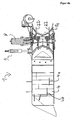
- the device 1 in addition to the lower feed wheel 7a designed as an upper feed wheel 7b counter element, ie a Schmidteinzugsrad, which are driven in opposite directions.
- the lateral surface 20 a plurality of pairs of recesses, of which in FIG. 7 for example, the pairs 21 ', 21 "and 21''' are marked.
- retraction elements 22 of which, for example, in FIG. 9 three feeder elements 22a, 22b and 22c are marked.
- the lateral surface 20 is octagonal in cross-section, wherein the eight thereby resulting sections of the lateral surface of the lower Einzugsrades 7a each have two recesses and thus each penetrated by a pair of intake elements 22.
- FIG. 9 is due to the central section in the sectional view only one feeder element 22 of the pairs of feeder elements to see.
- the catchment elements 22 are rotatable about a common axis of rotation (reference G in FIG FIG. 9 rotatably arranged.
- the rotation axis G is arranged parallel to the axis of rotation H of the lower feed wheel 7a and spaced therefrom. Due to the arrangement of the upper feed wheel 7b arranged approximately vertically above the axis of rotation H of the lower feed wheel 7a axis of rotation results in the FIG. 9 by "X" marked compression area, which essentially represents the area between the longitudinal extents of the two feed wheels.
- the axis of rotation G is spaced both in the direction of movement C of the device forward, as well as in a direction away from the compression region direction of the rotation axis H of the lower Einzugsrades 7a.
- catchment elements in a forward position with respect to the direction of movement of the device for example catchment element 22a in FIG. 9 further protrudes from the lateral surface 20 of the lower feed wheel 7a, as in a position to the rear, for example, when due to the rotation of the feed wheel 7a, the collection element 22a, the position of the feeder element 22c in FIG. 9 has reached.
- plant parts adhering to the growth aids 2 are thus additionally captured by the intake elements 22 and guided into the compression region between the two intake wheels 7a and 7b.
- the feeder elements already protrude less from the lateral surface 20 and in a position to the rear, for example, according to retraction element 22c in FIG. 9
- the feeder elements do not protrude or only slightly out of the lateral surface.
- the catchment elements thus release the plant parts in the rearward position, so that wrapping of the feed wheel 7a through the plant parts is avoided and, moreover, an action of the catchment elements on the growth aids 2 in this position is avoided.
- the pairwise arrangement of the intake elements 22 on the common axis of rotation next to each other is also in the sectional view according to FIG. 4b seen.
- the lower feed wheel 7a has an approximately trough-shaped cross-section parallel to the axis of rotation, wherein starting from a central position in the axial direction of the radius increases toward the outside.
- the feed wheel 7a has pull-in webs 23 extending parallel to the axis of rotation, which have a U-shaped region 23a for centrally guiding the growth aids in the axially central position and a plurality of serrated formations 23b for better collection of the plant parts.
- the collection elements 22 are elongated with rectangular cross section and have according to sectional view BB on the lying in the direction of rotation (top in FIG. 8 ) rounded edges. At the side facing away from the axis of rotation, the feeder elements 22 have a clearance angle ⁇ of 10 °, whereby the collection effect on the plant parts is increased.
- the feeder elements On the side facing the axis of rotation, the feeder elements have a C-profile for gripping around the sleeve surrounding the axis of rotation.
- the opening L of the C-profile is chosen such that it is smaller than the outer radius of the sleeve.
- the feed finger 22 can not be detached from the sleeve and thus not from the axis of rotation. If, however, the sleeve is displaced in the axial direction, so that the C-profile engages directly around the axis of rotation, the retraction element 22 can be removed, since the distance L is greater than the diameter of the axis of rotation.
- the pair of feed elements 22 with the shortest distance has a length of about 17 cm.
- the length of the intake elements 22 increases with increasing distance in the axial direction between the pairs up to a length of about 22 cm of the intake elements with the maximum distance in the axial direction.
- the plant guide unit 7 is due to the design with the lower feed wheel 7a and the upper feed wheel 7b, which have parallel axes of rotation, in particular for the entry of plant parts which extend approximately along the growth aids 2 and of plant parts, which in the front view according to FIG. 3 are approximately perpendicular, ie plant parts whose longitudinal extent, at least in projection on a plane perpendicular to the Growth aids 2 is approximately perpendicular to the axis of rotation of the lower feed wheel 7a and thus also perpendicular to the axis of rotation of the upper feed wheel 7b.
- the plant alignment unit 12 comprises a plant transport means 13 designed as a screw conveyor.
- the plant transport means 13 thus constitutes a linear conveying means.
- the plant alignment unit 12 further comprises a holder in which the plant transporting means 13 is rotatably mounted and a third motor 14 for rotating the screw conveyor of the plant transport means of the plant alignment unit 12 about the axis of the screw conveyor.
- the plant alignment unit 12 is arranged in front of the plant guide unit 7 with regard to the relative movement of the growth aid guide to the device. Plant parts adhering to the growth aids 2 thus reach first into the area of action of the plant alignment unit 12 and then into the area of action of the plant guidance unit 7.
- Plant parts which project laterally from the growth aids 2 can thus be grasped and moved by the plant transport means 13.
- the direction of rotation is chosen such that the detected by the plant transport means 13. Plant parts in FIG. 3 to be moved upwards.
- FIG. 3 Exemplary is in FIG. 3 as a dotted line a plant part F shown schematically, which is approximately perpendicular to the growth aids 2 and horizontally as shown in FIG FIG. 3 projects.
- the plant part F is detected by the plant transport means 13 and with its in FIG. 3 moved right end up, so that the plant part F rotation about the growth aids 2 in the counterclockwise direction in the illustration FIG. 3 performs.
- the plant part F is further approximated the plant guide unit 7, but applies to this in a vertical or nearly vertical orientation as shown in FIG. 3 and can thus be fed easily with the plant guide unit 7.
- Trained as a screw conveyor plant transport means 13 has in the axial extent a length of about 60 cm with a screw pitch of about 12.5 cm and a diameter of about 12.5 cm.
- the diameter of the screw decreases continuously toward the respective end of the axis of the screw.
- the part of the transporting means 13 designed as a screw conveyor is operated by means of the third motor 14 at a rotational speed of about 220 rpm.
- the plant guide unit 7 is due to the design with the lower feed wheel 7a and the upper feed wheel 7b, which have parallel axes of rotation, in particular for the entry of plant parts which extend approximately along the growth aids 2 and of plant parts, which in the front view according to FIG. 3 are approximately perpendicular, ie plant parts whose longitudinal extent is at least in projection on a plane perpendicular to the growth aids 2 approximately perpendicular to the axis of rotation of the lower feed wheel 7a and thus also perpendicular to the axis of rotation of the upper feed wheel 7b.
- the plant alignment unit 12 comprises a plant transport means 13 designed as a screw conveyor.
- the plant transport means 13 thus constitutes a linear conveying means.
- the plant alignment unit 12 further comprises a holder in which the plant transporting means 13 is rotatably mounted and a third motor 14 for rotating the screw conveyor of the plant transport means of the plant alignment unit 12 about the axis of the screw conveyor.
- the plant alignment unit 12 is arranged in front of the plant guide unit 7 with regard to the relative movement of the growth aid guide to the device. Plant parts adhering to the growth aids 2 thus reach first into the area of action of the plant alignment unit 12 and then into the area of action of the plant guidance unit 7.
- Plant parts which project laterally from the growth aids 2 can thus be grasped and moved by the plant transport means 13.
- the direction of rotation is chosen such that the plant parts detected by the plant transport means 13 in FIG. 3 to be moved upwards.
- FIG. 3 Exemplary is in FIG. 3 as a dotted line a plant part F shown schematically, which is approximately perpendicular to the growth aids 2 and horizontally as shown in FIG FIG. 3 projects.
- the plant part F is detected by the plant transport means 13 and with its in FIG. 3 moved right end up, so that the plant part F rotation about the growth aids 2 in the counterclockwise direction in the illustration FIG. 3 performs.
- the plant part F is further approximated the plant guide unit 7, but applies to this in a vertical or nearly vertical orientation as shown in FIG. 3 and can thus be fed easily with the plant guide unit 7.
- Trained as a screw conveyor plant transport means 13 has in the axial extent a length of about 60 cm with a screw pitch of about 12.5 cm and a diameter of about 12.5 cm.
- the diameter of the screw decreases continuously toward the respective end of the axis of the screw.
- the part of the transporting means 13 designed as a screw conveyor is operated by means of the third motor 14 at a rotational speed of about 220 rpm.
Landscapes
- Life Sciences & Earth Sciences (AREA)
- Environmental Sciences (AREA)
- Biodiversity & Conservation Biology (AREA)
- Ecology (AREA)
- Forests & Forestry (AREA)
- Botany (AREA)
- Cultivation Of Plants (AREA)
Description
Die Erfindung betrifft eine Vorrichtung zum Entfernen von Pflanzenteilen von mindestens einer länglichen, zugstabilen, biegeschlaffen Wuchshilfe während einer Bewegung der Vorrichtung entlang der Wuchshilfe gemäß Oberbegriff des Anspruchs 1.The invention relates to a device for removing parts of plants from at least one elongated, zugstabilen, limp growth aid during movement of the device along the growth aid according to the preamble of
Bei dem Anbau von Pflanzen sind längliche, zugstabile, biegeschlaffe Wuchshilfen, wie beispielsweise Seile oder Drähte bekannt, um die Pflanzen zu stützen und/oder den Wuchs der Pflanzen zu beeinflussen. So ist beispielsweise im Weinbau die Verwendung von Spalierdrähten bekannt, beispielsweise bei der Guyot- und auch bei der Kordonerziehung.In the cultivation of plants elongated, zugstabile, pliable growth aids, such as ropes or wires are known to support the plants and / or to influence the growth of the plants. For example, in viticulture the use of trellis wires is known, for example in Guyot and also in cordon education.
Bei dem Anbau von Pflanzen mittels vorgenannter Wuchshilfen ist es typischerweise zu bestimmten Zeitpunkten wünschenswert, Pflanzenteile abzutrennen und die an den Wuchshilfen noch anhaftenden, abgetrennten Pflanzenteile zu entfernen. So ist es beispielsweise im Weinbau üblich, Rebentriebe abzutrennen, beispielsweise mittels eines motorisch angetriebenen Vorschneiders. Eine Vielzahl von abgetrennten Rebentrieben bleibt jedoch nach dem Abtrennen von der Rebenpflanze an der Wuchshilfe haften, aufgrund von Verrankung oder zumindest teilweisem Umschließen der Wuchshilfe durch den Rebentrieb oder einzelne Fortsätze des Rebentriebs.In the cultivation of plants by means of the above-mentioned growth aids, it is typically desirable at certain times to separate plant parts and to remove the growth aids still adherent, separated plant parts. For example, it is customary in viticulture to separate vine shoots, for example by means of a motor-driven pre-cutter. A large number of separated vine shoots, however, remain attached to the growth aid after separation from the vine plant, due to limitation or at least partially surrounding the growth aid by the vine shoot or individual extensions of the vine shoot.
Das Entfernen der an der Wuchshilfe anhaftenden Pflanzenteile erfolgt üblicherweise manuell und stellt einen aufwändigen, mühsamen Arbeitsvorgang dar.The removal of adhering to the growth aid plant parts is usually done manually and represents a complex, tedious operation.
Zur Vereinfachung dieses Vorgangs ist aus der
Aus
Grundsätzlich problematisch bei dem Entfernen von Pflanzenteilen von der Wuchshilfe ist, dass die Pflanzenteile unregelmäßig gewachsen und insbesondere nach einem Abschneiden von der Hauptpflanze in unterschiedlichsten Richtungen und in unterschiedlichen Längen von der Wuchshilfe abstehen können, so dass hohe Anforderungen an das Verfahren und die Vorrichtung zum Entfernen aller Ausgestaltungen der Pflanzenteile bestehen. Darüber hinaus können die Pflanzenteile durch Umwicklungen und/oder Verästelungen eine stabile Verbindung mit der Wuchshilfe aufweisen, die schwierig zu lösen ist.Fundamentally problematic in the removal of plant parts from the growth aid is that the plant parts can grow irregularly and in particular after cutting off the main plant in different directions and in different lengths of the growth aid can stand so high demands on the method and device for removing consist of all the forms of plant parts. In addition, the plant parts can by wrapping and / or ramifications have a stable connection with the growth aid, which is difficult to solve.
Der vorliegenden Erfindung liegt daher die Aufgabe zugrunde, die vorbekannten Vorrichtungen und Verfahren zum Entfernen von Pflanzenteilen von einer Wuchshilfe zu verbessern und die Fehleranfälligkeit und daraus resultierende notwendige Unterbrechungen während des Betriebs zu verringern.The present invention is therefore based on the object to improve the prior art devices and methods for removing parts of plants from a growth aid and to reduce the susceptibility to errors and the resulting interruptions during operation.
Gelöst ist diese Aufgabe durch eine Vorrichtung gemäß Anspruch 1. Vorteilhafte Ausgestaltungen der Vorrichtung finden sich in den Ansprüchen 2 bis 15. Hiermit wird der Wortlaut aller Ansprüche durch ausdrückliche Bezugnahme in die Beschreibung aufgenommen.This object is achieved by a device according to
Die erfindungsgemäße Vorrichtung zum Entfernen von Pflanzenteilen von mindestens einer länglichen, zugstabilen, biegeschlaffen Wuchshilfe während einer Bewegung der Vorrichtung entlang der Wuchshilfe umfasst eine Wuchshilfeführung, zum Führen der Wuchshilfe während der Bewegung der Vorrichtung entlang der Wuchshilfe. Weiterhin umfasst die Vorrichtung eine Ablöseeinheit. Die Vorrichtung umfasst weiterhin eine Pflanzenführungseinheit zum Komprimieren und/oder Zuführen der an der Wuchshilfe anhaftenden Pflanzenteile zu der Ablöseeinheit.The device according to the invention for removing parts of plants from at least one elongated, tensile stable, non-limp growth aid during a movement of the device along the growth aid comprises a growth aid guide for guiding the growth aid during the movement of the device along the growth aid. Furthermore, the device comprises a detachment unit. The apparatus further comprises a plant guide unit for compressing and / or feeding the plant parts adhering to the growth aid to the detachment unit.
Die Ablöseeinheit umfasst mindestens ein Ablöseelement, welches Ablöseelement derart beweglich an der Vorrichtung angeordnet ist, dass bei Betrieb durch Bewegung des Ablöseelementes Pflanzenteile von der Wuchshilfe zumindest teilweise ablösbar sind.The detachment unit comprises at least one detachment element, which detachment element is movably arranged on the device in such a way that, when operated by movement of the detachment element, plant parts are at least partially detachable from the growth aid.
Die Pflanzenführungseinheit umfasst mindestens ein drehbar angeordnetes Einzugsrad, zum Einzug und/oder zum Komprimieren der Pflanzenteile.The plant management unit comprises at least one rotatably arranged feed wheel for feeding in and / or for compressing the plant parts.
Wesentlich ist, dass die Pflanzenführungseinheit eine Mehrzahl von Einzugselementen umfasst. Jedes der Mehrzahl von Einzugselementen ist beweglich und eine reale oder gedachte Mantelfläche des Einzugsrades durchdringend angeordnet, derart, dass bei einer Drehung des Einzugsrades das Einzugselement in einer Stellung nach vorne hinsichtlich der Bewegungsrichtung der Vorrichtung weiter aus der Mantelfläche herausragt als in einer Stellung nach hinten.It is essential that the plant management unit comprises a plurality of intake elements. Each of the plurality of intake elements is movable and a real or imaginary lateral surface of the Einzugsrades penetrating arranged such that upon rotation of the Einzugsrades the intake element in a forward position with respect to the direction of movement of the device further protrudes from the lateral surface than in a rearward position.
Es liegt im Rahmen der Erfindung, die Mantelfläche des Einzugsrades im Wesentlichen geschlossen mit Ausnehmungen für die Einzugselemente auszugestalten. In diesem Fall kann von einer realen Mantelfläche gesprochen werden. Ebenso liegt es im Rahmen der Erfindung, dass die Mantelfläche des Einzugsrades eine oder mehrere Ausnehmungen aufweist, beispielsweise durch Einzelelemente wie Stäbe entlang des Umfangs des Einzugsrades gebildet ist. In solchen Fällen ist die Mantelfläche die kleinste Umhüllung des Einzugsrades und stellt somit eine gedachte Mantelfläche dar.It is within the scope of the invention to design the lateral surface of the feed wheel substantially closed with recesses for the intake elements. In this case, one can speak of a real lateral surface. It is also within the scope of the invention that the lateral surface of the feed wheel has one or more recesses, for example formed by individual elements such as rods along the circumference of the Einzugsrades. In such cases, the lateral surface is the smallest envelope of the feed wheel and thus represents an imaginary lateral surface.
Die Erfindung ist in der Erkenntnis des Anmelders begründet, dass insbesondere aufgrund des unregelmäßigen Wuchses in Bewegungsrichtung der Vorrichtung vor der Pflanzenführungseinheit häufig Störungen derart auftreten, dass sich Pflanzenteile vor der Pflanzenführungseinheit aufstauen oder zumindest in ungünstigen Einzugspositionen zum Komprimieren und/oder Zuführen durch die Pflanzenführungseinheit befinden. Hierdurch werden insbesondere folgende Fehler verursacht:
- Durch das Aufstauen einer Vielzahl von Pflanzenteilen kann es zu unregelmäßigem Zuführen der Pflanzenteile mittels der Pflanzenführungseinheit zu der Ablöseeinheit kommen, so dass zunächst sich eine Vielzahl von Pflanzenteilen vor der Pflanzenführungseinheit aufstaut und anschließend diese Pflanzenteile in Form eines Knäuels oder großen Ballens der Ablöseeinheit zugeführt werden, so dass häufig aufgrund solch eines Knäuels oder Ballens die Wuchshilfe in einen ungünstigen Verlaufsweg abgelenkt wird, so dass insbesondere ein hohes Risiko besteht, dass die Wuchshilfe durch das Ablöseelement der Ablöseeinheit beschädigt, häufig durchtrennt wird.
- By damming a plurality of plant parts may lead to irregular feeding of the plant parts by the plant guide unit to the detachment unit, so that initially accumulates a variety of plant parts in front of the plant management unit and then these parts of plants in the form of a ball or large bale of the detachment unit are supplied so that often due to such a ball or bale the growth aid is deflected in an unfavorable course, so that in particular there is a high risk that the growth aid is damaged by the release element of the detachment unit, often severed.
Darüber hinaus kann bereits ein Aufstauen von Pflanzenteilen oder bereits eine ungünstige Orientierung von Pflanzenteile vor der Pflanzenführungseinheit dazu führen, dass trotz des Verwendens einer Wuchshilfeführung die Wuchshilfe in einen ungünstigen Verlaufsweg abgelenkt wird, so dass ebenso ein hohes Risiko besteht, dass die Wuchshilfe durch das Ablöseelement der Ablöseeinheit beschädigt, häufig durchtrennt wird.In addition, already a damming of parts of plants or already an unfavorable orientation of plant parts before the plant management unit cause that despite the use of a growth guide the growth aid is deflected in an unfavorable course, so that there is a high risk that the growth aid by the separation element the detaching unit is damaged, often severed.
Untersuchungen des Anmelders haben gezeigt, dass die Verwendung eines Einzugsrades, dessen Mantelfläche von einer Mehrzahl von Einzugselementen durchdrungen ist, die Bildung vorgenannter Staus und damit das Anhäufen vorgenannter Knäuel oder Ballen vermieden werden. Denn mittels der Einzugselemente werden die Pflanzenteile zusätzlich erfasst und hierdurch auch bei ungünstiger Orientierung von dem Einzugsrad eingezogen und komprimiert und/oder der Ablöseeinheit zugeführt.Investigations by the applicant have shown that the use of a feed wheel, whose lateral surface is penetrated by a plurality of intake elements, the formation of the aforementioned congestion and thus the accumulation of aforementioned balls or bales are avoided. For by means of the catchment elements, the plant parts are additionally detected and thereby drawn in at unfavorable orientation of the feed wheel and compressed and / or fed to the detachment unit.
Die Untersuchungen des Anmelders haben jedoch gezeigt, dass das Anbringen starrer Einzugselemente auf dem Einzugsrad etwa nach Art eines Zahnrades oder in der Art von Spikes auf einem Autoreifen keine zufrieden stellende Funktionalität ergibt: Einerseits ist es notwendig, die Einzugselemente in einer ausreichenden Länge aus der Mantelfläche herausragen zu lassen, um ein effizientes Eingreifen in die Pflanzenteile zu ermöglichen. Andererseits bergen die aus der Mantelfläche herausragenden Einzugselemente ein erhebliches Risiko, dass Pflanzenteile von den Einzugsfingern von der Wuchshilfe gelöst werden und sich um das Einzugsrad herumwickeln und insbesondere, dass die Wuchshilfe in Stellung der Einzugselemente nach hinten hinsichtlich der Bewegungsrichtung der Vorrichtung von den Einzugselementen erfasst und beschädigt und/oder in eine ungünstige Position geschoben und/oder um das Einzugsrad herumgewickelt wird.However, the applicant's investigations have shown that the provision of rigid draw-in elements on the feed wheel such as a gear or in the manner of spikes on a car tire does not provide satisfactory functionality: On the one hand, it is necessary that the catchment elements of a sufficient length from the lateral surface stand out for an efficient To allow intervention in the plant parts. On the other hand, the catch elements protruding from the lateral surface pose a considerable risk that plant parts are detached from the growth fingers by the growth aid and wrap around the feed wheel and, in particular, that the growth aid in the position of the intake elements is caught by the intake elements in the rearward direction with respect to the direction of movement of the device damaged and / or pushed into an unfavorable position and / or wrapped around the feed wheel.
Neben dem Vorsehen von Einzugselementen zum zusätzlichen Erfassen der Pflanzenteile ist es somit wesentlich, dass jedes der Mehrzahl von Einzugselementen in einer Stellung nach vorne hinsichtlich der Bewegungsrichtung der Vorrichtung weiter aus der Mantelfläche herausragt als in einer Stellung nach hinten. Hierdurch ist gewährleistet, dass in dem in Bewegungsrichtung vorne liegenden Bereich des Einzugrades, in dem ein Erfassen der Pflanzenteile wesentlich ist, die Einzugselemente weiter aus der Mantelfläche herausragen und somit ein effizientes Erfassen gewährleistet ist und in dem hinten liegenden Bereich des Einzugsrades, in dem die Pflanzenteile bereits komprimiert bzw. für die Zuführung zu der Ablöseeinheit geeignet gemacht sind, ragen die Einzugselemente weniger weit aus der Mantelfläche heraus, so dass eine nachteilige Einwirkung auf die Pflanzenteile und die Wuchshilfe wie zuvor beschrieben ausgeschlossen wird.In addition to the provision of catchment elements for additional detection of the plant parts, it is thus essential that each of the plurality of catchment elements in a forward position with respect to the direction of movement of the device protrudes further from the lateral surface than in a position to the rear. This ensures that in the forward direction in the direction of the feed wheel, in which a detection of the plant parts is essential, the feeder elements further protrude from the lateral surface and thus an efficient detection is ensured and in the rear area of the feed wheel, in which the Plant parts are already compressed or made suitable for feeding to the detaching unit, the catchment elements protrude less far out of the lateral surface, so that an adverse effect on the plant parts and the growth aid is excluded as described above.
Durch die Ausbildung des Einzugsrades und der Einzugselemente bei der erfindungsgemäßen Vorrichtung wird somit in effektiver Weise eine typische Fehlerquelle nahezu vollständig ausgeschlossen, so dass durch diese Fehler begründete Betriebsunterbrechungen und Beschädigungen der Wuchshilfe ebenfalls nahezu ausgeschlossen sind.Due to the design of the feed wheel and the intake elements in the device according to the invention thus effectively a typical source of error is almost completely excluded, so that justified by these errors business interruptions and damage to the growth aid are also almost impossible.
Hierdurch wird das Verhältnis zwischen Betriebs- und Wartungsdauer der erfindungsgemäßen Vorrichtung erheblich verbessert und damit die Wirtschaftlichkeit erhöht.As a result, the ratio between the operating and maintenance period of the device according to the invention is significantly improved and thus increases the efficiency.
Vorzugsweise sind Einzugsrad und die Mehrzahl von Einzugselementen derart ausgebildet, dass in Stellung nach vorne die Einzugselemente mit einer um mindestens einen Faktor 2 größeren Länge aus der Mantelfläche herausragen als in Stellung nach hinten, bevorzugt um mindestens einen Faktor 3, weiter bevorzugt um mindestens einen Faktor 5.Preferably, the feed wheel and the plurality of intake elements are designed such that, in the forward position, the intake elements protrude from the outer surface by a length which is greater by at least a factor of two than in FIG Position to the rear, preferably by at least a factor of 3, more preferably by at least a factor of 5.
Eine konstruktiv einfache Ausgestaltung ergibt sich in einer vorteilhaften Ausführungsform, bei der jedes der Mehrzahl von Einzugselementen drehbar mit einer Drehachse senkrecht zu einer Längserstreckung des Einzugselementes angeordnet ist. Insbesondere ist es vorteilhaft, dass alle Einzugselemente um eine gemeinsame Drehachse drehbar angeordnet sind, wobei bevorzugt die Mehrzahl von Einzugselementen in Axialrichtung ihrer gemeinsamen Drehachse versetzt, vorzugsweise nebeneinander angeordnet sind.A structurally simple embodiment results in an advantageous embodiment in which each of the plurality of intake elements is rotatably arranged with a rotation axis perpendicular to a longitudinal extent of the intake element. In particular, it is advantageous that all catchment elements are arranged rotatably about a common axis of rotation, wherein preferably the plurality of catchment elements offset in the axial direction of their common axis of rotation, preferably arranged side by side.
Hierdurch ergibt sich ein konstruktiver einfacher Aufbau, bei dem die Einzugselemente durch Führen des Einzugsrades sich mit dem Einzugsrad drehen, d. h. bei einer vollständigen Drehung des Einzugsrades vollführt jedes der Einzugselemente ebenfalls eine vollständige Drehung.This results in a constructive simple structure in which the intake elements rotate by guiding the intake wheel with the feed wheel, d. H. with a complete rotation of the feed wheel performs each of the feeder elements also a complete rotation.
Die vorgenannte Führung der Einzugselemente durch das Einzugsrad ist vorzugsweise dadurch ausgebildet, dass die Mantelfläche des Einzugsrades Ausnehmungen aufweist, durch welche sich die Einzugselemente erstrecken, so dass durch den Rand der Ausnehmung eine Drehbewegung des Rades auf das jeweilige Einzugselement übertragen wird.The above-mentioned guidance of the intake elements by the intake wheel is preferably formed in that the lateral surface of the Einzugsrades has recesses through which extend the intake elements, so that a rotational movement of the wheel is transmitted to the respective intake element by the edge of the recess.
Eine konstruktiv einfache und robuste Ausführungsform, bei der insbesondere die zuvor beschriebenen unterschiedlichen Längen des Herausragens der Einzugselemente abhängig von der Stellung der Einzugselemente gewährleistet ist, ergibt sich in einer vorzugsweisen Ausführungsform, bei der die Drehachse jedes der Mehrzahl.von Einzugselementen parallel zu der Drehachse des Einzugsrades ist, wobei vorzugsweise die Drehachse jedes der Mehrzahl von Einzugselementen gegenüber der Drehachse des Einzugsrades beabstandet ist. Aufgrund der parallelen, voneinander beabstandeten Drehachsen von den Einzugselementen einerseits und des Einzugsrades andererseits ergibt sich bei Drehung des Einzugsrades unmittelbar, dass jene Einzugselemente, welche in Richtung der Beabstandung der Drehachsen aus der Mantelfläche herausragen, um eine größere Länge aus der Mantelfläche herausragen als solche Einzugselemente, welche entgegengesetzt der Richtung der Beabstandung zwischen den beiden Drehachsen aus der Mantelfläche herausragen.A structurally simple and robust embodiment, in particular, the above-described different lengths of the protrusion of the feeder elements is guaranteed depending on the position of the feeder elements, results in a preferred embodiment in which the axis of rotation of each of the plurality of Einzugsselementen parallel to the axis of rotation of Einzugsrades is, wherein preferably the axis of rotation of each of the plurality of catchment elements is spaced from the axis of rotation of the Einzugsrades. Due to the parallel, spaced apart axes of rotation of the intake elements on the one hand and the feed wheel on the other hand arises upon rotation of the feed wheel immediately that those catchment elements which protrude in the direction of the spacing of the axes of rotation of the lateral surface to protrude from the lateral surface by a greater length than such catchment elements , which protrude from the lateral surface opposite to the direction of the spacing between the two axes of rotation.
Um zu gewährleisten, dass in Bewegungsrichtung der Vorrichtung nach vorne die Einzugselemente weiter herausragen als nach hinten, ist die Drehachse jedes der Mehrzahl von Einzugselementen bevorzugt zumindest in Bewegungsrichtung der Vorrichtung nach vorne von der Drehachse des Einzugsrades beabstandet angeordnet.In order to ensure that in the direction of movement of the device forward the catch elements protrude further than to the rear, the axis of rotation of each of the plurality of catch elements is preferably arranged at least in the direction of movement of the device forwardly spaced from the axis of rotation of the Einzugsrades.
Weiterhin ist es vorteilhaft, die Drehachse jedes der Mehrzahl von Einzugselementen zumindest in einer von einem Komprimierungsbereich des Einzugsrades abgewandten Richtung von der Drehachse des Einzugsrades beabstandet anzuordnen, insbesondere beide vorgenannten Beabstandungen zu kombinieren.Furthermore, it is advantageous to arrange the axis of rotation of each of the plurality of intake elements at least in a direction away from a compression region of the Einzugsrades direction spaced from the axis of rotation of the Einzugsrades, in particular to combine both aforementioned spacings.
Vorteilhafterweise weist die Pflanzenführungseinheit der erfindungsgemäßen Vorrichtung ein Gegenelement zu dem Einzugsrad auf, so dass zwischen Einzugsrad und Gegenelement eine Komprimierung zumindest unregelmäßig von der Wuchshilfe abstehender Pflanzenteile erfolgt. Vorteilhafterweise ist die Pflanzenführungseinheit derart ausgebildet, dass jedes der Mehrzahl von Einzugselementen das Gegenelement unabhängig von der Stellung des Einzugselementes nicht berührt. Um dennoch ein ausreichend breites Herausragen der Einzugselemente in Bewegungsrichtung der Vorrichtung vorne liegenden Bereich des Einzugsrades zu gewährleisten, ist es vorteilhaft, zusätzlich zu der vorgenannten Beabstandung nach vorne auch eine Beabstandung in Gegenrichtung der Position des Komprimierungsbereiches vorzusehen.Advantageously, the plant management unit of the device according to the invention has a counter element to the feed wheel, so that between the feed wheel and counter element a compression takes place at least irregularly from the plant growing parts protruding from the growth aid. Advantageously, the plant management unit is designed such that each of the plurality of intake elements does not touch the counter element regardless of the position of the intake element. In order nevertheless to ensure a sufficiently broad protrusion of the catchment elements in the direction of movement of the device in front region of the feed wheel, it is advantageous to provide in addition to the aforementioned spacing to the front and a spacing in the opposite direction of the position of the compression region.
Vorzugsweise sind die Einzugselemente in Axialrichtung Ihrer Drehachse in Gruppen angeordnet. Dies bedeutet, dass in axialer Projektion die Einzugselemente einer Gruppe stets die gleiche Stellung aufweisen. Insbesondere ist es vorteilhaft, Zweiergruppen auszubilden, d. h. die Einzugselemente paarweise in Axialrichtung ihrer Drehachse zu gruppieren.Preferably, the feeder elements are arranged in groups in the axial direction of their axis of rotation. This means that in axial projection, the intake elements of a group always have the same position. In particular, it is advantageous to form groups of two, i. H. to group the feeder elements in pairs in the axial direction of their axis of rotation.
Hierdurch ergibt sich der Vorteil, dass die Pflanzenteile stets durch mindestens zwei Einzugselemente erfasst werden können und ein Entgleiten der Pflanzenelemente beispielsweise durch Drehung vermieden wird.This results in the advantage that the plant parts can always be detected by at least two catchment elements and a slipping of the plant elements is avoided, for example by rotation.
Insbesondere ist es vorteilhaft, die erfindungsgemäße Vorrichtung derart auszubilden, dass die Wuchshilfe bei Betrieb zwischen den Einzugselementen einer Gruppe verläuft, so dass mindestens ein Einzugselement rechts und ein Einzugselement links der Wuchshilfe den Einzug der Pflanzen gewährleistet.In particular, it is advantageous to form the device according to the invention such that the growth aid in operation between the intake elements of a Group runs so that at least one catchment element right and a catchment element left of the growth aid ensures the entry of the plants.
Untersuchungen des Anmelders haben ergeben, dass es weiterhin vorteilhaft ist, dass die Gruppen in Axialrichtung unterschiedliche Abstände zwischen den Einzugselementen aufweisen, so dass an unterschiedlichen Positionen aufgrund der unterschiedlichen Abstände Pflanzenteile ergriffen werden können.Investigations by the Applicant have shown that it is furthermore advantageous that the groups have different distances between the intake elements in the axial direction, so that parts of plants can be gripped at different positions due to the different distances.
Insbesondere ist es vorteilhaft, dass in Drehrichtung des Einzugsrades die Gruppen einen zunehmenden Abstand der Einzugselemente in Axialrichtung aufweisen. Dies bedeutet, dass bei Betrachten eines sich drehenden Einzugsrades von vorne sich der Abstand zwischen zwei aufeinander folgenden Einzugselementen verringert, um nach einer vollständigen Drehung wieder auf den maximalen Abstand zu springen. In dieser Ansicht ergibt sich somit ein V-förmiges Zusammenführen der Einzugselemente bei Betrachten eines drehenden Einzugsrades von vorne, welches bereits eine Komprimierungsfunktion auf die Pflanzenteile ausüben kann. Insbesondere ist bei dieser Anordnung, bei welcher zusätzlich die Wuchshilfe zwischen den Einzugselementen einer Gruppe geführt ist vorteilhaft, dass durch das vorbeschriebene sich einander Annähern der Einzugselemente in Axialrichtung die Wuchshilfe mit jeder vollständigen Drehung des Einzugsrades in den mittigen Bereich der Einzugselemente mit dem kleinsten Abstand zentriert wird. Hierdurch kann somit auch ein Herausrutschen oder eine Verschiebung der Wuchshilfe senkrecht zur Längserstreckung der Wuchshilfe korrigiert werden.In particular, it is advantageous that in the direction of rotation of the feed wheel, the groups have an increasing distance of the feeder elements in the axial direction. This means that when viewing a rotating feed wheel from the front, the distance between two successive feeder elements is reduced to jump back to the maximum distance after a complete rotation. In this view, this results in a V-shaped merging of the intake elements when viewing a rotating feed wheel from the front, which can already exert a compression function on the plant parts. In particular, in this arrangement, in which in addition the growth aid is guided between the intake elements of a group advantageous that centered by the above each approaching the feeder elements in the axial direction, the growth aid with each complete rotation of the feed wheel in the central region of the feeder elements with the smallest distance becomes. As a result, a slipping out or a displacement of the growth aid can thus be corrected perpendicular to the longitudinal extent of the growth aid.
Wie zuvor ausgeführt, weist die Pflanzenführungseinheit der erfindungsgemäßen Vorrichtung vorzugsweise ein Gegenelement zu dem Einzugsrad auf, welches angeordnet ist, um zwischen Einzugsrad und Gegenelement einen Komprimierungsbereich für die Pflanzenteile auszubilden.As previously stated, the plant guide unit of the device according to the invention preferably has a counter element to the feed wheel, which is arranged to form a compression region for the plant parts between the feed wheel and the counter element.
Es liegt im Rahmen der Erfindung, das Gegenelement in konstruktiv einfacher Weise beispielsweise als Fläche, insbesondere als Blech auszubilden. Insbesondere effizient ist es hingegen in einer vorteilhaften Ausgestaltung, das Gegenelement als Gegeneinzugsrad auszubilden.It is within the scope of the invention to form the counter element in a structurally simple manner, for example as a surface, in particular as a sheet. In particular, it is particularly efficient in an advantageous embodiment, the counter-element form as Gegeneinzugsrad.
Das Gegeneinzugsrad weist vorzugsweise eine zu dem Einzugsrad parallele Drehachse auf und wird vorzugsweise gegensinnig zu dem Einzugsrad angetrieben.The Gegeneinzugsrad preferably has a parallel to the feed wheel axis of rotation and is preferably driven in opposite directions to the feed wheel.
Hierbei ist es vorteilhaft, dass die Einzugselemente im Komprimierungsbereich nahe an das Gegeneinzugsrad heranreichen, dieses jedoch nicht berühren. Insbesondere ist es vorteilhaft, dass die Mehrzahl von Einzugselementen im Komprimierungsbereich einen Abstand im Bereich 1 cm bis 20 cm, bevorzugt im Bereich 1 cm bis 10 cm, weiter bevorzugt im Bereich 1 cm bis 5 cm zu dem Gegenelement aufweisen.In this case, it is advantageous that the catchment elements in the compression area come close to the counter-engagement wheel, but do not touch it. In particular, it is advantageous that the plurality of intake elements have a distance in the range of 1 cm to 20 cm, preferably in the range of 1 cm to 10 cm, more preferably in the range of 1 cm to 5 cm to the counter element in the compression region.
Bei der Ausbildung des Gegenelementes als Gegeneinzugsrad ist es vorteilhaft, das Gegeneinzugsrad tonnenförmig auszubilden, mit einem in Axialrichtung nach außen hin abnehmenden Radius und die Axialrichtung weiter beabstandete Einzugselemente mit einer größeren Länge auszubilden, als die weniger weit beabstandeten Einzugselemente jeweils einer Gruppe. Hierdurch wird der nach außen hin abnehmende Radius des Gegeneinzugsrades durch die größere Länge der außen liegenden Einzugselemente kompensiert, so dass sich in etwa ein konstanter Abstand zwischen Einzugselement und Oberfläche des Gegeneinzugsrades ergibt, unabhängig von dem Abstand zwischen den Einzugselementen.In the formation of the counter element as Gegeneinzugsrad it is advantageous to form the Gegeneinzugsrad barrel-shaped with a decreasing in the axial direction outward radius and the axial direction more spaced catch elements with a greater length than the less widely spaced catchment elements each one group. As a result, the decreasing outwardly radius of Gegeneinzugsrades is compensated by the greater length of the outer intake elements, so that there is approximately a constant distance between intake element and surface of Gegeneinzugsrades, regardless of the distance between the intake elements.
Um ein Umwickeln des Einzugsrades durch Pflanzenteile zu vermeiden und insbesondere um negative Einwirkungen der Einzugselemente auf die Wuchshilfe zu vermeiden, ist es vorteilhaft, dass die Mehrzahl von Einzugselementen am entgegen der Bewegungsrichtung der Vorrichtung liegenden Ende des Komprimierungsbereiches um weniger als 5 cm, bevorzugt um weniger als 3 cm, weiter bevorzugt nicht aus der Mantelfläche des Einzugsrades herausragen. Bei Verwendung der erfindungsgemäßen Vorrichtung ist es vorteilhaft, wenn die Wuchshilfe im Komprimierungsbereich des Einzugsrades in Axialrichtung etwa mittig liegt. Vorzugsweise weist das Einzugsrad daher eine in Axialrichtung etwa mittige Führung für eine Wuchshilfe auf. Eine solche Führung kann beispielsweise durch einen keil- oder u-förmigen Einschnitt ausgebildet sein. Alternativ oder zusätzlich ist es vorteilhaft, dass das Einzugsrad mit einem in etwa wannenförmigen Querschnitt parallel zur Drehachse ausgebildet ist und bevorzugt in Axialrichtung von der Mitte ausgehend jeweils einen nach außen zunehmenden Radius aufweist.In order to avoid wrapping of the feed wheel by plant parts and in particular to avoid negative effects of the intake elements on the growth aid, it is advantageous that the plurality of intake elements at the opposite end of the direction of the device compression end of the device by less than 5 cm, preferably by less than 3 cm, more preferably not protrude from the lateral surface of the Einzugsrades. When using the device according to the invention, it is advantageous if the growth aid in the compression region of the feed wheel in the axial direction is approximately in the middle. Preferably, therefore, the feed wheel has an approximately centrally in the axial direction guide for a growth aid. Such a guide may be formed for example by a wedge or U-shaped incision. Alternatively or additionally, it is advantageous that the feed wheel is formed with an approximately trough-shaped cross-section parallel to the axis of rotation and preferably in Starting from the middle of the axial direction each has an outwardly increasing radius.
Insbesondere ist das Einzugsrad vorzugsweise felgenartig ausgebildet.In particular, the feed wheel is preferably rim-shaped.
Um eine einfache Wartung zu gewährleisten, ist vorzugsweise jedes der Mehrzahl von Einzugselementen lösbar an einer Drehachse angeordnet. Insbesondere ist es vorteilhaft, dass jedes der Mehrzahl von Einzugselementen lösbar und drehbar an einer Drehachse angeordnet ist. Hierdurch kann im Falle einer Beschädigung eines Einzugselementes dieses in einfacher Weise ausgetauscht werden.In order to ensure easy maintenance, preferably, each of the plurality of catchment elements is detachably arranged on a rotation axis. In particular, it is advantageous that each of the plurality of catchment elements is detachably and rotatably arranged on a rotation axis. As a result, in the event of damage to a feeder element this can be exchanged in a simple manner.
Ein einfacher Austausch der Einzugselemente ist insbesondere in einer vorteilhaften Ausführungsform der erfindungsgemäßen Vorrichtung möglich, bei der um die Drehachse der Mehrzahl von Einzugselementen eine oder mehrere in Axialrichtung wahlweise verschiebbare Hülsen angeordnet sind. Weiterhin umgreift vorzugsweise jedes der Mehrzahl von Einzugselementen zumindest eine Hülse teilweise, so dass bei Anordnung der Hülse im Umgreifungsbereich des Einzugselementes das Einzugselement nicht von der Hülse und damit nicht von der Drehachse lösbar ist, jedoch bei Verschieben der Hülse, so dass der Umgreifungsbereich unmittelbar an der Drehachse anliegt, ein Lösen des Einzugselementes möglich ist. Der Umgreifungsbereich des Einzugselementes weist somit vorzugsweise eine Öffnung auf, welche kleiner als der Außenradius der Hülse, jedoch größer als der Außenradius der Drehachse ist.A simple replacement of the feeder elements is possible in particular in an advantageous embodiment of the device according to the invention, in which one or more optionally axially displaceable sleeves are arranged around the axis of rotation of the plurality of feeder elements. Furthermore, preferably, each of the plurality of intake elements at least partially surrounds a sleeve, so that when the sleeve is arranged in the Umgreifungsbereich of the feeder element, the feeder element is not detachable from the sleeve and thus not from the axis of rotation, but upon displacement of the sleeve, so that the Umgreifungsbereich directly abuts the axis of rotation, a release of the catchment element is possible. The Umgreifungsbereich of the intake element thus preferably has an opening which is smaller than the outer radius of the sleeve, but larger than the outer radius of the axis of rotation.
Eine konstruktiv einfache Ausgestaltung ergibt sich in der vorteilhaften Ausführungsform, dass an jedem der Mehrzahl von Einzugselementen ein C-Profil zum Umgreifen der Hülse ausgebildet ist.A structurally simple embodiment results in the advantageous embodiment, that at each of the plurality of retraction elements, a C-shaped profile for gripping the sleeve is formed.
Vorzugsweise weist jedes der Mehrzahl von Einzugselementen an der in Drehrichtung weisenden Seite abgerundete Kanten auf. Insbesondere ist es vorteilhaft, dass jedes der Mehrzahl von Einzugselementen senkrecht zur Längserstreckung einen in etwa rechteckigen Querschnitt mit an der in Drehrichtung weisenden Seite abgerundeten Kanten aufweist. Hierdurch wird eine Beschädigung der Wuchshilfe bei Berührung durch die Einzugselemente vermieden. Vorzugsweise sind die Einzugselemente derart ausgebildet und angeordnet, dass die schmale Seite des rechteckigen Querschnitts in radiale Richtung und die längere Seite des rechteckigen Querschnitts in axiale Richtung weist. Hierdurch ist ein effizientes Eingreifen aufgrund der schmalen auf die Pflanzenteile einwirkenden Seite gewährleistet und gleichzeitig eine hohe Stabilität aufgrund der senkrecht zur Drehachse stehenden langen Seite des rechteckigen Querschnitts gewährleistet.Preferably, each of the plurality of catchment elements has rounded edges on the side facing in the direction of rotation. In particular, it is advantageous for each of the plurality of intake elements to have an approximately rectangular cross-section perpendicular to the longitudinal extent, with edges rounded on the side pointing in the direction of rotation. As a result, damage to the growth aid in contact with the intake elements is avoided. Preferably, the catchment elements are designed and arranged such that has the narrow side of the rectangular cross section in the radial direction and the longer side of the rectangular cross section in the axial direction. As a result, an efficient intervention is ensured due to the narrow side acting on the plant parts and at the same time ensures high stability due to the standing perpendicular to the axis of rotation long side of the rectangular cross-section.
Die Einzugselemente weisen vorzugsweise einen etwa rechteckigen Querschnitt mit einer Höhe im Bereich 1 cm bis 5 cm, bevorzugt 1 cm bis 3 cm, weiter bevorzugt von etwa 2 cm und einer Breite im Bereich 0,3 cm bis 2 cm, bevorzugt 0,3 cm bis 1 cm, weiter bevorzugt etwa 0,6 cm auf.The intake elements preferably have an approximately rectangular cross-section with a height in the
Die abgerundeten Kanten sind vorzugsweise mit einem Radius von etwa 0,5 mm ausgebildet.The rounded edges are preferably formed with a radius of about 0.5 mm.
Vorzugsweise sind die Einzugselemente bzw. die Gruppen von Einzugselementen in Umfangsrichtung des Einzugsrades etwa gleichmäßig verteilt.Preferably, the intake elements or the groups of intake elements are approximately evenly distributed in the circumferential direction of the feed wheel.
Vorzugsweise weist die Pflanzenführungseinheit zwischen 5 und 15 Einzugselemente bzw. Gruppen von Einzugselementen auf, bevorzugt zwischen 6 und 10 Einzugselementen bzw. Gruppen von Einzugselementen.Preferably, the plant management unit has between 5 and 15 intake elements or groups of intake elements, preferably between 6 and 10 intake elements or groups of intake elements.
Insbesondere ist es vorteilhaft, das Einzugsrad im Querschnitt senkrecht zur Drehachse in etwa achteckig auszuführen und acht Gruppen von jeweils zwei Einzugselementen anzuordnen.In particular, it is advantageous to perform the feed wheel in cross-section perpendicular to the axis of rotation approximately octagonal and to arrange eight groups of two intake elements.
Die Einzugselemente weisen vorzugsweise eine Länge im Bereich 10 cm bis 30 cm, bevorzugt 15 cm bis 25 cm auf.The catchment elements preferably have a length in the
Untersuchungen des Anmelders haben weiterhin ergeben, dass eine Optimierung des Eingriffs in die Pflanzenteile und der Förderung der Pflanzenteile durch die Einzugselemente erzielt wird, indem an den radial nach außen abstehenden Enden der Einzugselemente ein Freiwinkel ausgebildet ist; vorzugsweise einen Freiwinkel im Bereich 2° bis 30°, weiter bevorzugt im Bereich 5° bis 15°, insbesondere etwa 10°.Investigations by the applicant have further shown that an optimization of the engagement in the plant parts and the promotion of the plant parts is achieved by the feeder elements by a clearance angle is formed at the radially outwardly projecting ends of the feeder elements; preferably a clearance angle in the
Die Einzugselemente sind vorzugsweise aus Metall hergestellt und insbesondere vorzugsweise galvanisch verzinkt. Hierdurch ist eine lange Haltbarkeit gewährleistet.The feeder elements are preferably made of metal and in particular preferably galvanized. This ensures a long shelf life.
Die erfindungsgemäße Vorrichtung ist insbesondere zum Entfernen von Rebentrieben von mindestens einem Spalierdraht im Weinbau geeignet. Insbesondere von solchen Rebentrieben, die zwar von der Rebe abgeschnitten sind, jedoch noch an dem Spalierdraht anhaften, wie typischerweise Rebentriebe nach dem händischen Vorschnitt.The device according to the invention is particularly suitable for removing vine shoots of at least one trellis wire in viticulture. In particular of such vine shoots, which are indeed cut from the vine, but still adhere to the trellis wire, as typically vine shoots after the manual pruning.
Ebenso ist die erfindungsgemäße Vorrichtung auch bei anderen Pflanzenerziehungen anwendbar, bei denen Pflanzenteile an einer länglichen, zugstabilen, biegeschlaffen Wuchshilfe anhaften, insbesondere bereits von der Hauptpflanze abgetrennte Pflanzenteile.Likewise, the device according to the invention is also applicable to other plant educations in which plant parts adhere to an elongated, zugstabilen, limp growth aid, in particular already separated from the main plant parts of plants.
Die erfindungsgemäße Vorrichtung umfasst vorzugsweise eine Haltevorrichtung, mittels dessen die Vorrichtung an einem Fahrzeug wie beispielsweise einem Traktor angeordnet ist. Vorzugsweise ist die Haltevorrichtung derart ausgebildet, dass die Vorrichtung zum Entfernen hinsichtlich der Höhe und des seitlichen Abstands zu dem Fahrzeug wahlweise bewegt werden kann. Solche Haltevorrichtungen sind bei Traktoren bereits bekannt.The device according to the invention preferably comprises a holding device, by means of which the device is arranged on a vehicle such as a tractor. Preferably, the holding device is designed such that the device for removal with respect to the height and the lateral distance to the vehicle can be selectively moved. Such holding devices are already known in tractors.
Es ist insbesondere vorteilhaft, die erfindungsgemäße Vorrichtung grundsätzlich nach der Vorrichtung gemäß
Untersuchungen des Anmelders haben ergeben, dass die Fehleranfälligkeit hinsichtlich des Einzugs und/oder der Komprimierung der Zuführung der Pflanzenteile zu der Ablöseeinheit mittels der Pflanzenführungseinheit zusätzlich verringert wird, wenn die Vorrichtung in einer vorteilhaften Ausführungsform zusätzlich mindestens eine Pflanzenrichteinheit umfasst, mit mindestens einem motorisch angetriebenen Pflanzentransportmittel, welche Pflanzenausrichteinheit vor der Pflanzenführungseinheit angeordnet ist, hinsichtlich der Relativbewegung der Wuchshilfeführung zu der Vorrichtung und welche Pflanzenausrichteinheit derart angeordnet und dazu ausgebildet ist, mittels des Pflanzentransportmittels von der Wuchshilfe abstehende Pflanzenteile in Richtung einer bevorzugten Einzugsorientierung der Pflanzenführungseinheit zu bewegen.Investigations by the Applicant have shown that the error rate with regard to the intake and / or compression of the supply of the plant parts to the detachment unit by means of the plant management unit is additionally reduced if the device additionally comprises at least one plant straightening unit in an advantageous embodiment, with at least one motor-driven plant transport means , which plant alignment unit the plant management unit is arranged, with respect to the relative movement of the growth aid guide to the device and which plant alignment arranged and designed to move by means of the plant transport from the growth aid projecting plant parts in the direction of a preferred feed orientation of the plant management unit.
Die Pflanzenausrichteinheit ist vorzugsweise derart angeordnet und dazu ausgebildet, mittels des Pflanzentransportmittels von der Wuchshilfe abstehende Pflanzenteile in Richtung einer bevorzugten Einzugsorientierung der Pflanzenführungseinheit zu bewegen.The plant alignment unit is preferably arranged and designed to move plant parts projecting from the growth aid by means of the plant transporting means in the direction of a preferred intake orientation of the plant management unit.
Untersuchungen des Anmelders haben gezeigt, dass die Verwendung einer Pflanzenausrichteinheit, welche mittels mindestens eines motorisch angetriebenen Pflanzentransportmittels die Pflanzen zumindest in Richtung einer bevorzugten Einzugsorientierung der Pflanzenzuführungseinheit bewegt, die Bildung vorgenannter Staus und damit das Anhäufen vorgenannter Knäuel oder Ballen vermieden wird.Investigations by the applicant have shown that the use of a plant alignment unit, which moves the plants by means of at least one motor-driven plant transport means at least in the direction of a preferred intake orientation of the plant supply unit, the formation of the aforementioned congestion and thus the accumulation of aforementioned balls or bales is avoided.
Vorzugsweise ist die Pflanzenausrichteinheit derart angeordnet und dazu ausgebildet, mittels des Pflanzentransportmittels von der Wuchshilfe abstehende Pflanzenteile zu drehen. Vorzugsweise erfolgt die Drehung um eine Drehachse, welche Drehachse in etwa mit der Längsachse der Wuchshilfe im Bereich der Pflanzenausrichteinheit übereinstimmt.Preferably, the plant alignment unit is arranged and designed to rotate by means of the plant transport means from the growth aid projecting plant parts. Preferably, the rotation takes place about an axis of rotation, which axis of rotation coincides approximately with the longitudinal axis of the growth aid in the region of the plant alignment unit.
Untersuchungen des Anmelders haben gezeigt, dass typische Pflanzenzuführungseinheiten eine bevorzugte Einzugsorientierung hinsichtlich einer Erstreckung von Pflanzenteilen senkrecht zu der Wuchshilfe aufweisen. Durch Drehen solcher Pflanzenteile, die von der Wuchshilfe abstehen, insbesondere die hinsichtlich ihrer Längserstreckung senkrecht oder in einem nicht vernachlässigbaren Winkel, (beispielsweise > 30°) von der Wuchshilfe abstehen, wird die Funktion der Pflanzenführungseinheit durch eine Ausrichtung solcher Pflanzenteile erheblich verbessert. Hierbei ist es wünschenswert, die Pflanzenteile möglichst in die bevorzugte Einzugsorientierung zu bringen. Eine Verbesserung wird jedoch auch dann bereits erzielt, wenn die Pflanzenteile lediglich über eine gewisse Teilstrecke in Richtung der bevorzugten Einzugsorientierung bewegt werden.Applicant's investigations have shown that typical plant feed units have a preferred intake orientation with respect to extension of plant parts perpendicular to the growth aid. By rotating such parts of the plant which protrude from the growth aid, in particular those which protrude perpendicularly or at a non-negligible angle (for example> 30 °) from the growth aid, the function of the plant management unit is considerably improved by an alignment of such plant parts. It is desirable to bring the plant parts as possible in the preferred orientation Einzugsorientierung. However, an improvement is already achieved when the plant parts are moved only over a certain distance in the direction of the preferred feed orientation.
Da die Pflanzenteile an der Wuchshilfe anhaften und ein Ablösen von der Wuchshilfe oder einer Relativverschiebung der Pflanzenteile zu der Wuchshilfe mittels der Pflanzenausrichteinheit in der Regel nicht möglich ist, ist es vorteilhaft, wie zuvor beschrieben mittels des Pflanzentransportmittels die abstehenden Pflanzenteile zu drehen. Denn auch solche Pflanzenteile, die durch Verästelungen oder um Windungen stabil mit der Wuchshilfe verbunden sind, lassen sich in der Regel durch geringe Krafteinwirkung drehen, insbesondere um eine Drehachse, welche in etwa mit der Längsachse der Wuchshilfe im Bereich der Pflanzenausrichteinheit übereinstimmt.Since the plant parts adhere to the growth aid and detachment from the growth aid or a relative displacement of the plant parts to the growth aid by means of plant alignment usually is not possible, it is advantageous, as described above by means of the plant transport means to rotate the protruding plant parts. For even those parts of plants that are stably connected by ramifications or windings with the growth aid, can usually be rotated by a small force, in particular about a rotation axis, which coincides approximately with the longitudinal axis of the growth aid in the plant alignment unit.
Durch das vorgeschaltete Drehen insbesondere von der Wuchshilfe abstehender Pflanzenteile, welche sich in einer ungünstigen Orientierung hinsichtlich des Einzugs durch die Pflanzenzuführungseinheit befinden, wird somit in einfacher Weise die Fehleranfälligkeit der erfindungsgemäßen Vorrichtung und des erfindungsgemäßen Verfahrens erheblich verringert.As a result of the preceding turning of parts of plants projecting from the growth aid, which are in an unfavorable orientation with respect to the intake by the plant supply unit, the susceptibility to error of the device according to the invention and the method according to the invention is thus considerably reduced in a simple manner.
Untersuchungen des Anmelders haben ergeben, dass das Pflanzentransportmittel vorzugsweise als lineares Fördermittel ausgebildet ist. Hierdurch ergibt sich ein robuster und kostengünstiger Aufbau des Fördermittels und gleichzeitig eine effiziente und fehlerunanfällige Orientierung von der Wuchshilfe abstehender Pflanzenteile in Richtung einer bevorzugten Einzugsorientierung der Pflanzenzuführungseinheit.Investigations by the applicant have shown that the plant transport agent is preferably designed as a linear conveyor. This results in a robust and cost-effective design of the conveyor and at the same time an efficient and error-prone orientation of the growing aid projecting plant parts in the direction of a preferred feed orientation of the plant supply unit.
Es liegt im Rahmen der Erfindung, typische, dem Fachmann bekannte lineare Fördermittel zu verwenden, beispielsweise Förderbänder oder Rollenbahnen.It is within the scope of the invention to use typical linear conveying means known to the person skilled in the art, for example conveyor belts or roller conveyors.
Insbesondere vorteilhaft ist jedoch die Ausbildung des Pflanzentransportmittels als Förderschnecke. Untersuchungen des Anmelders haben ergeben, dass eine Förderschnecke robust und gleichzeitig kostengünstig ausbildbar ist, beispielsweise durch die an sich bekannten in Metall ausgebildeten Förderschnecken, welche mittels eines Motors, wie beispielsweise eines Hydraulikmotors oder eines Elektromotors, um die Symmetrieachse der Schneckenwelle gedreht werden.Particularly advantageous, however, is the formation of the plant transport means as a screw conveyor. Investigations by the applicant have shown that a screw conveyor is robust and at the same time inexpensively formed, for example, by the known in metal screw conveyors, which are rotated by means of a motor, such as a hydraulic motor or an electric motor to the axis of symmetry of the worm shaft.
Durch eine solche Schnecke wird in einfacher Weise ein linearer Transport des Teilbereiches des Pflanzenteils, welcher mit der Schnecke in Berührung kommt, erzielt. Durch den linearen Transport wird in einfacher Weise aufgrund des Anhaftens des Pflanzenteils an der Wuchshilfe eine Drehung des Pflanzenteils um die Wuchshilfe erzielt. Die Ausbildung des Pflanzentransportmittels als Förderschnecke weist darüber hinaus den Vorteil auf, dass im Falle einer Umwicklung der Förderschnecke durch Pflanzen oder andere Objekte eine solche in kurzer Zeit manuell behoben werden kann und darüber hinaus nur eine geringe Verletzungsgefahr besteht, selbst wenn ein Benutzer im Betrieb mit der sich drehenden Förderschnecke in Berührung kommen sollte.By such a screw, a linear transport of the portion of the plant part, which comes into contact with the screw, is achieved in a simple manner. Due to the linear transport a rotation of the plant part is achieved by the growth aid in a simple manner due to the adherence of the plant part of the growth aid. The formation of the plant transport means as screw conveyor also has the advantage that in case of wrapping the screw conveyor by plants or other objects such can be corrected manually in a short time and beyond there is only a small risk of injury, even if a user in the company the rotating screw conveyor should come into contact.
Die Förderschnecke ist vorzugsweise an einem Ende, bevorzugt an beiden Enden, konisch zulaufend ausgebildet. Dies bedeutet, dass in axialer Richtung zu dem jeweiligen Ende hin sich die Ganghöhe der Schnecke verringert. Untersuchungen des Anmelders haben gezeigt, dass durch ein solches konisches Zulaufen Fehler aufgrund eines Umwickelns der Schnecke durch Pflanzenteile nahezu ausgeschlossen werden.The screw conveyor is preferably formed at one end, preferably at both ends, tapered. This means that in the axial direction to the respective end, the pitch of the screw is reduced. Applicant's investigations have shown that such conical feeding virtually eliminates errors due to wrapping of the screw by plant parts.
Die Pflanzenausrichteinheit umfasst vorzugsweise einen motorischen Antrieb zum Drehen der Förderschnecke. Untersuchungen des Anmelders haben ergeben, dass insbesondere ein Drehen der Förderschnecke mit einer Umdrehungsgeschwindigkeit im Bereich 100 U/min bis 400 U/min, bevorzugt im Bereich 200 U/min bis 250 U/min vorteilhaft ist.The plant alignment unit preferably comprises a motor drive for rotating the conveyor screw. Investigations by the Applicant have shown that, in particular, it is advantageous to rotate the screw conveyor at a speed of rotation in the range from 100 rpm to 400 rpm, preferably in the range from 200 rpm to 250 rpm.
Weiterhin ist es vorteilhaft, dass die Förderschnecke einen Durchmesser im Bereich 3 cm bis 25 cm, bevorzugt im Bereich 5 cm bis 22 cm, weiter bevorzugt im Bereich 9 cm bis 20 cm aufweist.Furthermore, it is advantageous that the conveyor screw has a diameter in the range 3 cm to 25 cm, preferably in the range 5 cm to 22 cm, more preferably in the
Weiterhin ist es vorteilhaft, dass die Förderschnecke eine Ganghöhe im Bereich 10 cm bis 15 cm, bevorzugt etwa 12,5 cm aufweist.Furthermore, it is advantageous that the screw conveyor has a pitch in the
Die vorgenannten vorteilhaften Ausgestaltungen ergeben jeweils für sich genommen und insbesondere in Kombination zweier oder mehrerer der vorgenannten vorteilhaften Ausgestaltungen ein optimiertes Förderverhalten der Förderschnecke für die Pflanzenteile.The aforementioned advantageous embodiments, taken individually and in particular in combination of two or more of the aforementioned advantageous embodiments, result in an optimized conveying behavior of the conveyor screw for the plant parts.
Vorzugsweise ist das als lineares Fördermittel ausgebildete Pflanzentransportmittel mit Förderrichtung in einem vorgegebenen Winkel zu der bevorzugten Einzugsorientierung der Pflanzenführungseinheit angeordnet. Untersuchungen des Anmelders haben ergeben, dass insbesondere eine Anordnung in einem Winkel im Bereich 3° bis 20°, bevorzugt im Bereich 5° bis 15°, weiter bevorzugt etwa 9° vorteilhaft ist. Durch die vorgenannten vorzugsweisen Anstellwinkel bei Draufsicht von vorne auf die erfindungsgemäße Vorrichtung wird erzielt, dass bei Drehen der Pflanzenteile um die Wuchshilfe diese möglichst weit in Richtung der bevorzugten Einzugsorientierung durch das lineare Fördermittel gedreht werden.Preferably, the plant transport means designed as a linear conveyor is arranged with conveying direction at a predetermined angle to the preferred intake orientation of the plant management unit. Investigations by the applicant have shown that in particular an arrangement at an angle in the range of 3 ° to 20 °, preferably in the range of 5 ° to 15 °, more preferably about 9 ° is advantageous. By the aforementioned preferred angle of attack in plan view from the front of the device according to the invention is achieved that upon rotation of the plant parts to the growth aid they are rotated as far as possible in the direction of preferred feed orientation by the linear conveyor.
Hierbei liegt es im Rahmen der Erfindung, dass der Winkel zwischen Förderrichtung des linearen Fördermittels und der bevorzugten Einzugsorientierung der Pflanzenführungseinheit durch einen Benutzer wahlweise vorgebbar ist, insbesondere dass das lineare Fördermittel schwenkbar und wahlweise feststellbar an der Vorrichtung angeordnet ist. Hierdurch kann der Benutzer den vorgenannten Winkel gegebenenfalls optimieren.In this case, it is within the scope of the invention that the angle between the conveying direction of the linear conveyor and the preferred feed orientation of the plant management unit by a user is optionally predetermined, in particular that the linear conveyor is pivotally mounted and optionally detectable on the device. This allows the user to optionally optimize the aforementioned angle.
Es liegt im Rahmen der Erfindung, dass bei Draufsicht von vorne in einer Ebene senkrecht zur Längserstreckung der Wuchshilfe eine Drehung der Pflanzenteile durch das lineare Fördermittel in oder entgegen des Uhrzeigersinns erfolgt. Untersuchungen des Anmelders haben ergeben, dass vorzugsweise das lineare Fördermittel derart ausgebildet ist, dass bei Betrieb von dem Fördermittel erfasste Teilbereiche der Pflanzenteile nach oben bewegt werden. Hierdurch wird der Kontakt zwischen Pflanzenteil und linearem Fördermittel verbessert und dadurch das Einwirken und die Ausrichtung optimiert.It is within the scope of the invention that in plan view from the front in a plane perpendicular to the longitudinal extent of the growth aid rotation of the plant parts by the linear conveyor in or counterclockwise takes place. Investigations by the applicant have shown that preferably the linear conveyor is designed such that during operation of the conveyor detected portions of the plant parts are moved upward. As a result, the contact between the plant part and linear conveyor is improved, thereby optimizing the action and the orientation.
Der lineare. Förderweg des Fördermittels weist vorzugsweise eine Länge im Bereich von 0,3 m bis 1,2 m, bevorzugt im Bereich 0,5 m bis 0,7 m auf. Untersuchungen des Anmelders haben ergeben, dass größere Längen die Handhabung der Vorrichtung erheblich erschweren und kleinere Längen keine ausreichende Bewegung der Pflanzenteile in Richtung der bevorzugten Einzugsorientierung ermöglichen.The linear one. The conveying path of the conveying means preferably has a length in the range from 0.3 m to 1.2 m, preferably in the range from 0.5 m to 0.7 m. Investigations by the Applicant have shown that larger lengths considerably complicate the handling of the device and smaller lengths do not allow sufficient movement of the plant parts in the direction of the preferred orientation of feed.
Ebenso liegt es im Rahmen der Erfindung, den linearen Förderweg auf zwei oder mehr Förderelemente aufzuteilen, beispielsweise durch Aneinanderreihung zwei oder mehrere linearer Fördermittel. Insbesondere ist es vorteilhaft, zwischen den Fördermitteln in einer Ebene senkrecht zur Längserstreckung der Wuchshilfe einen Winkel im Bereich 5° bis 45°, bevorzugt im Bereich 10° bis 20°, weiter bevorzugt etwa 15° vorzusehen. Hierdurch wird eine Kreisbewegung senkrecht zu der Wuchshilfe, welche Kreisbewegung ein von dem Fördermittel linear bewegtes Pflanzenteil ausführt, angenähert.It is also within the scope of the invention to divide the linear conveying path on two or more conveying elements, for example by juxtaposing two or more linear conveyors. In particular, it is advantageous to provide an angle in the range of 5 ° to 45 °, preferably in the range of 10 ° to 20 °, more preferably approximately 15 °, between the conveying means in a plane perpendicular to the longitudinal extension of the growth aid. In this way, a circular motion is approximated perpendicular to the growth aid, which circular movement executes a plant part moved linearly by the conveying means.
Der Abstand der Pflanzenausrichteinheit senkrecht zu einer die Pflanzenführungseinheit durchlaufenden Wuchshilfe ist vorzugsweise < 50 cm und liegt bevorzugt im Bereich zwischen 5 cm und 30 cm, weiter bevorzugt im Bereich zwischen 10 cm und 20 cm zu der Wuchshilfe. Hierdurch ist gewährleistet, dass einerseits keine Knäuel oder Ballen mit den vorgenannten negativen Folgen entstehen und andererseits Pflanzenzeile, die problemlos von der Pflanzenführungseinheit eingezogen werden, nicht unnötigerweise von der Pflanzenausrichteinheit beaufschlagt werden.The distance of the plant alignment unit perpendicular to a plant guide unit passing through growth aid is preferably <50 cm and is preferably in the range between 5 cm and 30 cm, more preferably in the range between 10 cm and 20 cm to the growth aid. This ensures that, on the one hand, no balls or bales are produced with the aforementioned negative consequences and, on the other hand, plant rows, which are easily pulled in by the plant management unit, are not unnecessarily loaded by the plant alignment unit.
Hinsichtlich des Abstandes in Richtung der Längserstreckung einer die Pflanzenführungseinheit durchlaufenden Wuchshilfe ist das Pflanzentransportmittel vorzugsweise mit einem Abstand < 50 cm, bevorzugt im Bereich zwischen 5 cm und 30 cm, weiter bevorzugt im Bereich zwischen 10 cm und 20 cm zu der Pflanzenführungseinheit angeordnet. Hierdurch wird ein nachträgliches Verrutschen oder Verdrehen der Pflanzenteile nach Beaufschlagung durch das Pflanzentransportmittel nahezu vermieden.With regard to the distance in the direction of the longitudinal extent of a growth aid passing through the plant management unit, the plant transport medium is preferably arranged at a distance <50 cm, preferably in the range between 5 cm and 30 cm, more preferably in the range between 10 cm and 20 cm from the plant management unit. As a result, subsequent slippage or rotation of the plant parts after exposure to the plant transport agent is almost avoided.
Vorzugsweise sind Ablöseeinheit und Wuchshilfeführung derart zusammenwirkend ausgebildet, dass bei Betrieb das Ablöseelement im Bereich der Drehachse einen Abstand in Axialrichtung im Bereich von 5 mm bis 30 mm, bevorzugt im Bereich von 10 mm bis 20 mm, weiter bevorzugt etwa 15 mm zu der Wuchshilfe aufweist.Preferably, the detachment unit and the auxiliary power guide are configured cooperatively such that, in operation, the detachment element has a spacing in the axial direction in the range of 5 mm to 30 mm, preferably in the range of 10 mm to 20 mm, more preferably approximately 15 mm, to the growth aid ,
Als vorzugsweise Ausführungsform der erfindungsgemäßen Vorrichtung wird insbesondere auf die
Weitere Vorteile und Eigenschaften der vorliegenden Erfindung werden im Folgenden anhand von einem Ausführungsbeispiel und den Figuren erläutert. Dabei zeigt:
Figur 1- ein Ausführungsbeispiel der erfindungsgemäßen Vorrichtung in Seitenansicht mit dargestellten Wuchshilfen, wobei die
Seitenansicht gemäß Figur 1 bei Anordnen der Vorrichtung an eine Haltevorrichtung die der Haltevorrichtung abgewandte Seite zeigt; - Figur 1a
- eine Schnittdarstellung der Seitenansicht gemäß
Figur 1 , wobei die Schnittebene in der Rückansicht gemäßFigur 5 als Linie A gekennzeichnet ist; die Schnittebene steht senkrecht zur Zeichenebene gemäß Rückansicht inFigur 5 ; Figur 2- eine Seitenansicht der einer Haltevorrichtung zugewandten Seite;
- Figur 3
- eine Vorderansicht der Vorrichtung gemäß
Figur 1 mit dargestellten Wuchshilfen; Figur 4- eine Draufsicht von oben auf die
Vorrichtung gemäß Figur 1 ; Figur 4a- die
Draufsicht gemäß Figur 4 , wobei eine obere Abdeckung sowie ein oberes Einzugsrad entfernt wurden und Wuchshilfen dargestellt sind; - Figur 4b
- eine Schnittdarstellung gemäß Schnittlinie B in
Figur 3 , wobei die Schnittebene inFigur 3 senkrecht zur Zeichenebene steht; - Figur 5
- eine Ansicht von hinten auf die
Vorrichtung gemäß Figur 1 ; Figur 6- eine perspektivische Darstellung der Vorrichtung gemäß
Figur 1 ; Figur 7- eine Vorderansicht gemäß
Figur 3 , bei der lediglich das obere und das untere Einzugsrad dargestellt sind; Figur 8- in Teilbild a) eine perspektivische Darstellung eines Ausführungsbeispiels eines Einzugselementes in und Teilbild b) eine Seitenansicht des Einzugselementes sowie rechts daneben die Querschnittsfläche gemäß Schnittlinie BB in
Figur 8b , wobei die Schnittebene senkrecht zur Zeichenebene inFigur 8 Figur 9- eine Ausschnittvergrößerung aus
Figur 1a ,bei der insbesondere das Schnittbild des unteren Einzugsrades 7a dargestellt ist.
- FIG. 1
- an embodiment of the device according to the invention in side view with growth aids shown, wherein the side view according to
FIG. 1 when arranging the device to a holding device, the side facing away from the holding device; - FIG. 1a
- a sectional view of the side view according to
FIG. 1 , wherein the sectional plane in the rear view according toFIG. 5 marked as line A; the cutting plane is perpendicular to the drawing plane according to the rear view inFIG. 5 ; - FIG. 2
- a side view of a holding device facing side;
- FIG. 3
- a front view of the device according to
FIG. 1 with displayed growth aids; - FIG. 4
- a top view of the device according to
FIG. 1 ; - FIG. 4a
- the top view according to
FIG. 4 wherein an upper cover and an upper feed wheel have been removed and growth aids are shown; - FIG. 4b
- a sectional view along section line B in
FIG. 3 , where the cutting plane inFIG. 3 is perpendicular to the drawing plane; - FIG. 5
- a view from the rear of the device according to
FIG. 1 ; - FIG. 6
- a perspective view of the device according to
FIG. 1 ; - FIG. 7
- a front view according to
FIG. 3 in which only the upper and lower Einzugsrad are shown; - FIG. 8
- in partial image a) is a perspective view of an embodiment of a catchment element in and part of image b) a side view of the catchment element and right next to the cross-sectional area along section line BB in
FIG. 8b , wherein the sectional plane perpendicular to the plane inFIG. 8 stands and - FIG. 9
- a cutout enlargement
FIG. 1a in which in particular the sectional view of thelower feed wheel 7a is shown.
Sämtliche Figuren zeigen eine Vorrichtung 1 zum Entfernen von Pflanzenteilen von mindestens einer länglichen, zugstabilen, biegeschlaffen Wuchshilfe, welche Vorrichtung ein Ausführungsbeispiel der erfindungsgemäßen Vorrichtung darstellt. Gleiche Bezugszeichen in den Figuren bezeichnen gleiche Elemente.All figures show a
Die Vorrichtung 1 ist zum Entfernen von Pflanzenteilen von beliebigen länglichen, zugstabilen, biegeschlaffen Wuchshilfen geeignet, wie beispielsweise von Seilen oder Drähten. Insbesondere ist die Vorrichtung 1 zum Einsatz im Weinbau geeignet, um Rebentriebe, welche von der Rebe abgeschnitten sind, jedoch noch an als Spalierdrähten ausgebildeten Wuchshilfen 2 anhaften, zu entfernen. In den
Die Vorrichtung 1 umfasst eine Wuchshilfeführung 3, welche als nach oben offener Führungskanal mit einem in etwa u-förmigen Querschnitt senkrecht zur Längsachse einer in der Wuchshilfeführung 3 liegenden Wuchshilfe 2 ausgebildet ist. Mittels der Wuchshilfeführung 3 werden die Wuchshilfen 2 insbesondere im Bereich einer Ablöseeinheit 4 der Vorrichtung 1 geführt. Dies ist insbesondere in den
Die Ablöseeinheit 4 umfasst eine Vielzahl von Ablöseelementen, von denen in
Die Vorrichtung 1 umfasst weiterhin eine Pflanzenführungseinheit 7, welche ein unteres Einzugsrad 7a und ein oberes Einzugsrad 7b umfasst.The
Die Einzugsräder 7a und 7b werden mittels eines zweiten Motors 8 gegensinnig angetrieben, gemäß der Pfeile in
Zur Verwendung der Vorrichtung 1 wird diese mittels einer seitlich angeordneten Halterung 9 an einer (nicht dargestellten) Haltevorrichtung angebracht, welche Haltevorrichtung wiederum an einem (nicht dargestellten) Traktor angebracht ist. Mittels der Haltevorrichtung kann die Vorrichtung 1 bezüglich der Höhe variiert werden sowie bezüglich der seitlichen Ausrichtung in Fahrtrichtung rechts vor dem Traktor.To use the
Zur Verwendung der Vorrichtung in einem Weinberg, beispielsweise mit Guyot oder Kordonerziehung (wobei diese Beispiele nicht einschränkend sind), entweder die betreffenden Spalierdrähte per Hand von den Haltepfosten entlang einer Weinrebenzeile entfernt werden oder mittels entsprechender Haltevorrichtungen, wie beispielsweise nach oben offenen Klemmhaken, an den Haltepfosten angebracht sein, so dass sie nach oben abgezogen werden können. An dem ersten und letzten Pfosten einer Weinrebenzeile sind die Spalierdrähte unlösbar angebracht.To use the device in a vineyard, such as Guyot or cordon training (these examples being non-limiting), either manually remove the respective trellis wires from the support posts along a line of grapevines or by means of appropriate holding devices, such as open-topped hooks Holding post be attached so that they can be pulled off to the top. At the first and last post of a grapevine line the trellis wires are permanently attached.
Zu Beginn wird die Vorrichtung in eine Position nahe des ersten Pfostens gebracht und das obere Einzugsrad 7b sowie eine obere Abdeckung 10 (siehe
Die Wuchshilfen 2 verlaufen somit zwischen oberem Einzugsrad 7b und unterem Einzugsrad 7a (siehe
Anschließend wird mittels des Traktors die Vorrichtung 1 oberhalb der Pfosten der Weinrebenzeile entlanggefahren, so dass die Spalierdrähte 2 nach oben aus den Halterungen der Pfosten herausgezogen werden, sofern sie nicht bereits vorher aus entsprechenden Halterungen entfernt wurden. Der Traktor fährt nun entlang der Weinrebenzeile, so dass die Wuchshilfen 2 während dieser Bewegung durch die Vorrichtung 1 hindurchgeleitet werden. In den
An den Spalierdrähten anhaftende Pflanzenteile, insbesondere Rebentriebe werden somit zwischen den Einzugsrädern 7a und 7b hindurchgeführt und hierbei gegebenenfalls durch Zusammendrücken komprimiert und zu der Ablöseeinheit 4 (zusammen mit dem sich relativ zu der Vorrichtung 1 hindurchbewegenden Wuchshilfen 2) zugeführt.Plant parts adhering to the trellis wires, in particular vine shoots, are thus guided between the
Die als Schneidmesser ausgebildeten, rotierenden Ablöseelemente 4a, 4b lösen die Pflanzenteile von den Wuchshilfen 2 ab, durch Häckseln, Abschlagen und/oder Zerstückeln.The trained as a cutting blade, rotating
Mittels der Wuchshilfeführung 3 wird gewährleistet, dass die Wuchshilfen 2 nicht mit den Ablöseelementen 4a, 4b der Ablöseeinheit 4 in Kontakt kommen und somit nicht durch diese beschädigt und insbesondere nicht durchtrennt werden.By means of the growth aid guide 3 it is ensured that the growth aids 2 do not come into contact with the
Die Ablöseelemente 4a, 4b rotieren hierbei in der Ansicht in
Die abgelösten Pflanzenteile werden an einem Auslass 11 (siehe
Nachdem in einer Weinrebenzeile die Pflanzenteile von den Wuchshilfen 2 entfernt wurden, werden die Wuchshilfen 2 wieder in entsprechenden Halterungen an den Pfosten der Weinrebenzeile befestigt.After the plant parts have been removed from the growth aids 2 in a row of grapevines, the growth aids 2 are again secured in appropriate brackets to the posts of the grapevine line.
Ergänzend wird insbesondere zur Durchführung des Verfahrens auf
Wie insbesondere in
Wie insbesondere in den
Diese Ausnehmungen 21 sind von Einzugselementen 22 durchdrungen, von denen beispielsweise in
Die Mantelfläche 20 ist im Querschnitt achteckig ausgebildet, wobei die acht sich hierdurch ergebenden Sektionen der Mantelfläche des unteren Einzugsrades 7a jeweils zwei Ausnehmungen aufweisen und somit jeweils von einem Paar von Einzugselementen 22 durchdrungen sind.The lateral surface 20 is octagonal in cross-section, wherein the eight thereby resulting sections of the lateral surface of the
In
Die Einzugselemente 22 sind drehbar um eine gemeinsame Drehachse (Bezugszeichen G in
Hierdurch ergibt sich, dass Einzugselemente in einer Stellung nach vorne hinsichtlich der Bewegungsrichtung der Vorrichtung, beispielsweise Einzugselement 22a in
Durch diese Ausgestaltung des unteren Einzugsrades 7a und der Einzugselemente 22 werden an den Wuchshilfen 2 anhaftende Pflanzenteile somit zusätzlich von den Einzugselementen 22 erfasst und in den Komprimierungsbereich zwischen den beiden Einzugsrädern 7a und 7b geleitet. Im Komprimierungsbereich ragen die Einzugselemente bereits weniger aus der Mantelfläche 20 heraus und in einer Stellung nach hinten, beispielsweise gemäß Einzugselement 22c in
In
Wie insbesondere in
Die paarweise Anordnung der Einzugselemente 22 auf der gemeinsamen Drehachse nebeneinander ist ebenfalls in dem Schnittbild gemäß
Wie insbesondere in
Weiterhin weist das Einzugsrad 7a sich parallel zur Drehachse erstreckende Einzugsstege 23 auf, welche in axial mittiger Position einen u-förmigen Bereich 23a zur mittigen Führung der Wuchshilfen sowie mehrere zackenartige Ausbildungen 23b zum besseren Einzug der Pflanzenteile aufweisen.Furthermore, the
Wie in
An der der Drehachse zugewandten Seite weisen die Einzugselemente ein C-Profil zum Umgreifen der die Drehachse umgebenden Hülse auf. Die Öffnung L des C-Profils ist dabei derart gewählt, dass sie kleiner als der Außenradius der Hülse ist. Bei Betrieb kann sich der Einzugsfinger 22 somit nicht von der Hülse und damit nicht von der Drehachse lösen. Wird hingegen die Hülse in axialer Richtung verschoben, so dass das C-Profil unmittelbar die Drehachse umgreift, so kann das Einzugselement 22 entnommen werden, da der Abstand L größer als der Durchmesser der Drehachse ist.On the side facing the axis of rotation, the feeder elements have a C-profile for gripping around the sleeve surrounding the axis of rotation. The opening L of the C-profile is chosen such that it is smaller than the outer radius of the sleeve. In operation, the
Das Paar von Einzugselementen 22 mit dem geringsten Abstand weist eine Länge von etwa 17 cm auf. Hiervon ausgehend erhöht sich die Länge der Einzugselemente 22 mit größer werdendem Abstand in axialer Richtung zwischen den Paaren bis zu einer Länge von etwa 22 cm der Einzugselemente mit dem maximalen Abstand in axialer Richtung.The pair of
Die Pflanzenführungseinheit 7 ist aufgrund der Ausgestaltung mit dem unteren Einzugsrad 7a und dem oberen Einzugsrad 7b, welche parallele Drehachsen aufweisen, insbesondere zum Einzug von Pflanzenteilen, welche sich in etwa entlang der Wuchshilfen 2 erstrecken sowie von Pflanzenteilen, welche in der Vorderansicht gemäß
Bei von den Wuchshilfen 2 abstehenden Pflanzenteilen, die zumindest in Projektion auf eine senkrecht zu den Wuchshilfen 2 stehende Ebene eine in der Darstellung in
Die Vorrichtung 1 umfasst daher eine Pflanzenausrichteinheit 12. Die Pflanzenausrichteinheit 12 umfasst ein als Förderschnecke ausgebildetes Pflanzentransportmittel 13. Das Pflanzentransportmittel 13 stellt somit ein lineares Fördermittel dar. Die Pflanzenausrichteinheit 12 umfasst weiterhin eine Halterung, in der das Pflanzentransportmittel 13 drehbar gelagert ist sowie einen dritten Motor 14 zum Drehen der Förderschnecke des Pflanzentransportmittels der Pflanzenausrichteinheit 12 um die Achse der Förderschnecke.The
Die Pflanzenausrichteinheit 12 ist vor der Pflanzenführungseinheit 7 angeordnet, hinsichtlich der Relativbewegung der Wuchshilfeführung zu der Vorrichtung. An den Wuchshilfen 2 anhaftende Pflanzenteile gelangen somit zuerst in den Wirkungsbereich der Pflanzenausrichteinheit 12 und danach in den Wirkungsbereich der Pflanzenführungseinheit 7.The
Seitlich von den Wuchshilfen 2 abstehende Pflanzenteile können somit von dem Pflanzentransportmittel 13 erfasst und bewegt werden.Plant parts which project laterally from the growth aids 2 can thus be grasped and moved by the plant transport means 13.
Die Drehrichtung ist dabei derart gewählt, dass die von dem Pflanzentransportmittel 13 erfassten. Pflanzenteile in
Die lineare Bewegung solcher Pflanzenteile mittels des Pflanzentransportmittels 13 bewirkt typischerweise ein Drehen dieses Pflanzenteils um die Längsachse der Wuchshilfen 2, d. h. eine Drehung gegen den Uhrzeigersinn in der Ansicht gemäß
Ausgehend von einer waagrechten Position des Pflanzenteils F wird dieser somit mittels des Pflanzentransportmittels 13 in Richtung einer senkrechten Position gemäß Darstellung in
Aufgrund der Relativbewegung der Wuchshilfe 2 zu der Vorrichtung 1 und des Anhaftens des Pflanzenteils F an der Wuchshilfe 2 wird das Pflanzenteil F weiterhin der Pflanzenführungseinheit 7 angenähert, trifft auf diese jedoch in senkrecht oder nahezu senkrechter Ausrichtung gemäß der Darstellung in
Das als Förderschnecke ausgebildete Pflanzentransportmittel 13 weist in axialer Erstreckung eine Länge von etwa 60 cm auf mit einer Schneckensteigung von etwa 12,5 cm und einem Durchmesser von etwa 12,5 cm.Trained as a screw conveyor plant transport means 13 has in the axial extent a length of about 60 cm with a screw pitch of about 12.5 cm and a diameter of about 12.5 cm.
Wesentlich ist, dass die Förderschnecke in Endbereichen (Bezugszeichen G und H in
In den genannten Bereichen G und H verringert sich der Durchmesser der Schnecke kontinuierlich zu dem jeweiligen Ende der Achse der Schnecke hin.In the aforementioned ranges G and H, the diameter of the screw decreases continuously toward the respective end of the axis of the screw.
Ohne eine solche Ausgestaltung besteht ein höheres Risiko, dass an den Endbereichen des als Förderschnecke ausgebildeten Transportmittels des Pflanzentransportmittels 13 sich Pflanzenteile um die Förderschnecke herumwickeln.Without such a configuration, there is a higher risk that at the end regions of the conveying means of the plant transporting means 13 designed as a conveying screw, parts of plants will wrap around the conveying screw.
Durch die konische Ausgestaltung wird ein solcher Fehler nahezu ausgeschlossen.Due to the conical design such an error is almost impossible.
Der Teil der als Förderschnecke ausgebildeten Pflanzentransportmittel 13 wird mittels des dritten Motors 14 mit einer Umdrehungsgeschwindigkeit von etwa 220 U/min betrieben.The part of the transporting means 13 designed as a screw conveyor is operated by means of the
Mit der erfindungsgemäßen Vorrichtung und dem erfindungsgemäßen Verfahren wird somit ein wesentliches Fehlerpotential beim maschinellen Entfernen von Pflanzenteilen von mindestens einer Wuchshilfe beseitigt, indem mittels der Pflanzenausrichteinheit von der Wuchshilfe abstehende Pflanzenteile in Richtung einer bevorzugten Einzugsorientierung der Pflanzenführungseinheit bewegt werden.Thus, with the device according to the invention and the method according to the invention, a substantial potential for error in the mechanical removal of plant parts from at least one growth aid is eliminated by moving plant parts projecting from the growth aid in the direction of a preferred intake orientation of the plant management unit by means of the plant alignment unit.
Die Pflanzenführungseinheit 7 ist aufgrund der Ausgestaltung mit dem unteren Einzugsrad 7a und dem oberen Einzugsrad 7b, welche parallele Drehachsen aufweisen, insbesondere zum Einzug von Pflanzenteilen, welche sich in etwa entlang der Wuchshilfen 2 erstrecken sowie von Pflanzenteilen, welche in der Vorderansicht gemäß
Bei von den Wuchshilfen 2 abstehenden Pflanzenteilen, die zumindest in Projektion auf eine senkrecht zu den Wuchshilfen 2 stehende Ebene eine in der Darstellung in
Die Vorrichtung 1 umfasst daher eine Pflanzenausrichteinheit 12. Die Pflanzenausrichteinheit 12 umfasst ein als Förderschnecke ausgebildetes Pflanzentransportmittel 13. Das Pflanzentransportmittel 13 stellt somit ein lineares Fördermittel dar. Die Pflanzenausrichteinheit 12 umfasst weiterhin eine Halterung, in der das Pflanzentransportmittel 13 drehbar gelagert ist sowie einen dritten Motor 14 zum Drehen der Förderschnecke des Pflanzentransportmittels der Pflanzenausrichteinheit 12 um die Achse der Förderschnecke.The
Die Pflanzenausrichteinheit 12 ist vor der Pflanzenführungseinheit 7 angeordnet, hinsichtlich der Relativbewegung der Wuchshilfeführung zu der Vorrichtung. An den Wuchshilfen 2 anhaftende Pflanzenteile gelangen somit zuerst in den Wirkungsbereich der Pflanzenausrichteinheit 12 und danach in den Wirkungsbereich der Pflanzenführungseinheit 7.The
Seitlich von den Wuchshilfen 2 abstehende Pflanzenteile können somit von dem Pflanzentransportmittel 13 erfasst und bewegt werden.Plant parts which project laterally from the growth aids 2 can thus be grasped and moved by the plant transport means 13.
Die Drehrichtung ist dabei derart gewählt, dass die von dem Pflanzentransportmittel 13 erfassten Pflanzenteile in
Die lineare Bewegung solcher Pflanzenteile mittels des Pflanzentransportmittels 13 bewirkt typischerweise ein Drehen dieses Pflanzenteils um die Längsachse der Wuchshilfen 2, d. h. eine Drehung gegen den Uhrzeigersinn in der Ansicht gemäß
Ausgehend von einer waagrechten Position des Pflanzenteils F wird dieser somit mittels des Pflanzentransportmittels 13 in Richtung einer senkrechten Position gemäß Darstellung in
Aufgrund der Relativbewegung der Wuchshilfe 2 zu der Vorrichtung 1 und des Anhaftens des Pflanzenteils F an der Wuchshilfe 2 wird das Pflanzenteil F weiterhin der Pflanzenführungseinheit 7 angenähert, trifft auf diese jedoch in senkrecht oder nahezu senkrechter Ausrichtung gemäß der Darstellung in
Das als Förderschnecke ausgebildete Pflanzentransportmittel 13 weist in axialer Erstreckung eine Länge von etwa 60 cm auf mit einer Schneckensteigung von etwa 12,5 cm und einem Durchmesser von etwa 12,5 cm.Trained as a screw conveyor plant transport means 13 has in the axial extent a length of about 60 cm with a screw pitch of about 12.5 cm and a diameter of about 12.5 cm.
Wesentlich ist, dass die Förderschnecke in Endbereichen (Bezugszeichen G und H in
In den genannten Bereichen G und H verringert sich der Durchmesser der Schnecke kontinuierlich zu dem jeweiligen Ende der Achse der Schnecke hin.In the aforementioned ranges G and H, the diameter of the screw decreases continuously toward the respective end of the axis of the screw.
Ohne eine solche Ausgestaltung besteht ein höheres Risiko, dass an den Endbereichen des als Förderschnecke ausgebildeten Transportmittels des Pflanzentransportmittels 13 sich Pflanzenteile um die Förderschnecke herumwickeln. Durch die konische Ausgestaltung wird ein solcher Fehler nahezu ausgeschlossen.Without such a configuration, there is a higher risk that at the end regions of the conveying means of the plant transporting means 13 designed as a conveying screw, parts of plants will wrap around the conveying screw. Due to the conical design such an error is almost impossible.
Der Teil der als Förderschnecke ausgebildeten Pflanzentransportmittel 13 wird mittels des dritten Motors 14 mit einer Umdrehungsgeschwindigkeit von etwa 220 U/min betrieben.The part of the transporting means 13 designed as a screw conveyor is operated by means of the
Mit der erfindungsgemäßen Vorrichtung und dem erfindungsgemäßen Verfahren wird somit ein wesentliches Fehlerpotential beim maschinellen Entfernen von Pflanzenteilen von mindestens einer Wuchshilfe beseitigt, indem mittels der Pflanzenausrichteinheit von der Wuchshilfe abstehende Pflanzenteile in Richtung einer bevorzugten Einzugsorientierung der Pflanzenführungseinheit bewegt werden.Thus, with the device according to the invention and the method according to the invention, a substantial potential for error in the mechanical removal of plant parts from at least one growth aid is eliminated by moving plant parts projecting from the growth aid in the direction of a preferred intake orientation of the plant management unit by means of the plant alignment unit.
Claims (15)
- Device (1) for removing plant parts from at least one elongate, tensile-resistant, flexible growth support (2) during movement of the device (1) along the growth support (2), especially for removing vine shoots from at least one trellis wire,
comprising- a growth support guide means (3), for guiding the growth support (2) during the movement of the device (1) along the growth support (2),- a stripping unit (4) and- a plant guide unit (7) for compressing and/or supplying the plant parts adhering to the growth support (2) to the stripping unit (4),which stripping unit (4) comprises at least one stripping element, which stripping element is arranged on the device (1) so as to be movable in such a way that, during operation, plant parts are at least partly strippable from the growth support (2) by movement of the stripping element, and
which plant guide unit (7) comprises at least one rotatably arranged intake wheel, for intake and/or compression of the plant parts, characterised in that
the plant guide unit (7) comprises a plurality of intake elements (22a, 22b, 22c),
each of the plurality of intake elements (22a, 22b, 22c) being movable and arranged so as to pass through a real or notional outer surface of the intake wheel in such a way that, on rotation of the intake wheel, in a forward position relative to the direction of movement of the device (1) the intake element protrudes from the outer surface to a greater extent than in a rearward position. - Device (1) according to claim 1,
characterised in that
each of the plurality of intake elements (22a, 22b, 22c) is arranged so as to be rotatable with a shaft perpendicular to a longitudinal extent of the intake element,
preferably all the intake elements are arranged so as to be rotatable about a common shaft,
more especially the plurality of intake elements (22a, 22b, 22c) are arranged staggered in the axial direction of their common shaft, preferably one next to the other. - Device (1) according to claim 2,
characterised in that
the shaft of each of the plurality of intake elements (22a, 22b, 22c) is parallel to the shaft of the intake wheel,
preferably the shaft of each of the plurality of intake elements (22a, 22b, 22c) is arranged spaced apart from the shaft of the intake wheel at least towards the front in the direction of movement of the device (1), and/or
the shaft of each of the plurality of intake elements (22a, 22b, 22c) is arranged spaced apart from the shaft of the intake wheel at least in a direction facing away from a compression region of the intake wheel. - Device (1) according to any one of the preceding claims,
characterised in that
the intake elements are arranged in groups in the axial direction of their shaft, preferably in pairs. - Device (1) according to claim 4,
characterised in that
the groups have different distances between the intake elements (22a, 22b, 22c) in the axial direction,
preferably, in the direction of rotation of the intake wheel, the groups have increasing distances between the intake elements in the axial direction. - Device (1) according to any one of the preceding claims,
characterised in that
the plant guide unit (7) has a counter-element to the intake wheel, which counter-element is arranged to form a compression region for the plant parts between intake wheel and counter-element, preferably the counter-element is in the form of a counter-intake wheel. - Device (1) according to claim 6,
characterised in that
in the compression region the spacing of the intake elements from the counter-element is in the range of from 1 cm to 20 cm, preferably in the range of from 1 cm to 10 cm, more especially in the range of from 1 cm to 5 cm. - Device (1) according to claim 5 and either one of claims 6 and 7,
characterised in that
the counter-element is in the form of a counter-intake wheel the radius of which decreases towards the outside in the axial direction, and the intake elements that are spaced further apart in the axial direction are longer than the intake elements spaced less far apart. - Device (1) according to any one of the preceding claims,
characterised in that
the plurality of intake elements (22a, 22b, 22c) at that end of the compression region which is located opposite to the direction of movement of the device (1) protrude from the outer surface (20) of the intake wheel by less than 5 cm, especially by less than 3 cm, but preferably do not protrude therefrom. - Device (1) according to any one of preceding claims,
characterised in that
the intake wheel has a guide means for a growth support (2), which guide means is approximately central in the axial direction, preferably the intake wheel has an approximately trough-shaped cross-section parallel to the shaft, preferably having a radius that increases towards the outside in the axial direction. - Device (1) according to any one of the preceding claims,
characterised in that
the intake wheel has an outer surface (20) having openings (21', 21", 21'") and/or guide means for the intake elements. - Device (1) according to any one of the preceding claims,
characterised in that
each of the plurality of intake elements (22a, 22b, 22c) is detachably arranged on a shaft, preferably detachably and rotatably arranged on a shaft. - Device (1) according to claim 12,
characterised in that
one or more sleeves, which are displaceable as desired in the axial direction, are arranged around the shaft,
each of the plurality of intake elements (22a, 22b, 22c) engages around at least part of a sleeve, a C-profile for engagement around the sleeve preferably being formed on each of the plurality of intake elements (22a, 22b, 22c). - Device (1) according to any one of the preceding claims,
characterised in that
each of the plurality of intake elements (22a, 22b, 22c) has rounded edges on its side that faces in the direction of rotation, preferably each of the plurality of intake elements (22a, 22b, 22c) has, perpendicular to its longitudinal extent, an approximately rectangular cross-section the edges of which are rounded on the side that faces in the direction of rotation. - Device (1) according to any one of the preceding claims,
characterised in that
each of the plurality of intake elements (22a, 22b, 22c) has a clearance angle at the end protruding from the outer surface (20), preferably a clearance angle in the range of from 2° to 30°, more especially in the range of from 5° to 15°, especially about 10°.
Priority Applications (1)
| Application Number | Priority Date | Filing Date | Title |
|---|---|---|---|
| EP11001169.9A EP2486787B1 (en) | 2011-02-14 | 2011-02-14 | Device and method for removing plant parts from a climbing support |
Applications Claiming Priority (1)
| Application Number | Priority Date | Filing Date | Title |
|---|---|---|---|
| EP11001169.9A EP2486787B1 (en) | 2011-02-14 | 2011-02-14 | Device and method for removing plant parts from a climbing support |
Publications (2)
| Publication Number | Publication Date |
|---|---|
| EP2486787A1 EP2486787A1 (en) | 2012-08-15 |
| EP2486787B1 true EP2486787B1 (en) | 2013-04-24 |
Family
ID=44358073
Family Applications (1)
| Application Number | Title | Priority Date | Filing Date |
|---|---|---|---|
| EP11001169.9A Active EP2486787B1 (en) | 2011-02-14 | 2011-02-14 | Device and method for removing plant parts from a climbing support |
Country Status (1)
| Country | Link |
|---|---|
| EP (1) | EP2486787B1 (en) |
Cited By (2)
| Publication number | Priority date | Publication date | Assignee | Title |
|---|---|---|---|---|
| DE102013219651B3 (en) * | 2013-09-27 | 2014-11-20 | ERO-Gerätebau GmbH | Device for removing parts of plants from a growth aid |
| EP2823704A2 (en) | 2013-07-11 | 2015-01-14 | ERO-GERÄTEBAU GmbH | Device and method for removing plant pieces |
Families Citing this family (1)
| Publication number | Priority date | Publication date | Assignee | Title |
|---|---|---|---|---|
| FR2976447B1 (en) * | 2011-06-20 | 2013-07-12 | Jean-Yves Deze | MACHINE FOR AUTOMATICALLY SQUEEZING VINE SIZES |
Family Cites Families (3)
| Publication number | Priority date | Publication date | Assignee | Title |
|---|---|---|---|---|
| FR2746581B1 (en) * | 1996-04-01 | 1998-05-22 | Fontan Gerard | SEPARATING ELEVATOR |
| DE102004031088B4 (en) | 2004-06-28 | 2007-09-27 | Manfred Bermes | Method of removing branches from a trellis and apparatus therefor |
| CN101827516B (en) | 2007-10-19 | 2013-06-05 | 哈尼帕控股有限公司 | Method and apparatus for stripping material from a line |
-
2011
- 2011-02-14 EP EP11001169.9A patent/EP2486787B1/en active Active
Cited By (4)
| Publication number | Priority date | Publication date | Assignee | Title |
|---|---|---|---|---|
| EP2823704A2 (en) | 2013-07-11 | 2015-01-14 | ERO-GERÄTEBAU GmbH | Device and method for removing plant pieces |
| DE102013213623A1 (en) | 2013-07-11 | 2015-01-15 | ERO-Gerätebau GmbH | Device and method for removing parts of plants |
| DE102013219651B3 (en) * | 2013-09-27 | 2014-11-20 | ERO-Gerätebau GmbH | Device for removing parts of plants from a growth aid |
| EP2853149A1 (en) | 2013-09-27 | 2015-04-01 | ERO-GERÄTEBAU GmbH | Device for stripping shoots or plants from trellis |
Also Published As
| Publication number | Publication date |
|---|---|
| EP2486787A1 (en) | 2012-08-15 |
Similar Documents
| Publication | Publication Date | Title |
|---|---|---|
| WO1997017751A1 (en) | Insulation stripping device | |
| EP2649882B1 (en) | Dough separation and shaping device | |
| CH716237B1 (en) | Device for bundling leafy vegetables. | |
| EP2486787B1 (en) | Device and method for removing plant parts from a climbing support | |
| EP2266384B1 (en) | Weeding device for water plants and weeding boat with such a device | |
| EP2853149B1 (en) | Device for stripping shoots or plants from trellis | |
| EP2823704B1 (en) | Device and method for removing plant pieces | |
| DD213583B5 (en) | A silage cutter | |
| EP2486786A1 (en) | Device and method for removing plant parts from a support line | |
| WO2014198598A1 (en) | Picking arrangement | |
| DE102006044920A1 (en) | Post-picking device for a hops picking machine comprises a picking unit formed as an endless circulating conveyor belt | |
| EP2486788A1 (en) | Device and method for removing plant parts from a climbing support | |
| EP2486789A1 (en) | Device and method for removing plant parts from a climbing support | |
| DE102020116575B4 (en) | Device and method for cutting a cardboard blank at least laterally | |
| DE9105932U1 (en) | Pair of cutting rollers for corn picker | |
| DE2608160C3 (en) | Device for releasing cut wires from a disordered wire bundle, especially when feeding the wires to a processing machine | |
| EP2457443B1 (en) | Method for mechanical twisting of dough strips | |
| EP2884833B1 (en) | Device and method for removing branches, in particular canes, from an espalier | |
| WO2014198599A1 (en) | Harvester for mowing stalky crops | |
| BE1031090B1 (en) | Root crop separator and root crop harvester | |
| EP3651563B1 (en) | Device for preventing an accumulation of leaves and stems and associated harvesting machine | |
| DE102013019612B4 (en) | Bristle bundle feeding device | |
| DE102007010550A1 (en) | Apparatus and method for peeling elongated vegetables | |
| DE102007049344B4 (en) | Device for defoliation, in particular of grapevines | |
| AT505654B1 (en) | METHOD AND DEVICE FOR EFFECTING GEARING GEARS |
Legal Events
| Date | Code | Title | Description |
|---|---|---|---|
| PUAI | Public reference made under article 153(3) epc to a published international application that has entered the european phase |
Free format text: ORIGINAL CODE: 0009012 |
|
| 17P | Request for examination filed |
Effective date: 20120301 |
|
| AK | Designated contracting states |
Kind code of ref document: A1 Designated state(s): AL AT BE BG CH CY CZ DE DK EE ES FI FR GB GR HR HU IE IS IT LI LT LU LV MC MK MT NL NO PL PT RO RS SE SI SK SM TR |
|
| AX | Request for extension of the european patent |
Extension state: BA ME |
|
| GRAP | Despatch of communication of intention to grant a patent |
Free format text: ORIGINAL CODE: EPIDOSNIGR1 |
|
| RAP1 | Party data changed (applicant data changed or rights of an application transferred) |
Owner name: ERO-GERAETEBAU GMBH |
|
| GRAS | Grant fee paid |
Free format text: ORIGINAL CODE: EPIDOSNIGR3 |
|
| GRAA | (expected) grant |
Free format text: ORIGINAL CODE: 0009210 |
|
| AK | Designated contracting states |
Kind code of ref document: B1 Designated state(s): AL AT BE BG CH CY CZ DE DK EE ES FI FR GB GR HR HU IE IS IT LI LT LU LV MC MK MT NL NO PL PT RO RS SE SI SK SM TR |
|
| REG | Reference to a national code |
Ref country code: GB Ref legal event code: FG4D Free format text: NOT ENGLISH |
|
| REG | Reference to a national code |
Ref country code: CH Ref legal event code: EP |
|
| REG | Reference to a national code |
Ref country code: AT Ref legal event code: REF Ref document number: 607991 Country of ref document: AT Kind code of ref document: T Effective date: 20130515 |
|
| REG | Reference to a national code |
Ref country code: IE Ref legal event code: FG4D Free format text: LANGUAGE OF EP DOCUMENT: GERMAN |
|
| REG | Reference to a national code |
Ref country code: DE Ref legal event code: R096 Ref document number: 502011000636 Country of ref document: DE Effective date: 20130620 |
|
| REG | Reference to a national code |
Ref country code: LT Ref legal event code: MG4D |
|
| REG | Reference to a national code |
Ref country code: NL Ref legal event code: VDEP Effective date: 20130424 |
|
| PG25 | Lapsed in a contracting state [announced via postgrant information from national office to epo] |
Ref country code: PT Free format text: LAPSE BECAUSE OF FAILURE TO SUBMIT A TRANSLATION OF THE DESCRIPTION OR TO PAY THE FEE WITHIN THE PRESCRIBED TIME-LIMIT Effective date: 20130826 Ref country code: GR Free format text: LAPSE BECAUSE OF FAILURE TO SUBMIT A TRANSLATION OF THE DESCRIPTION OR TO PAY THE FEE WITHIN THE PRESCRIBED TIME-LIMIT Effective date: 20130725 Ref country code: ES Free format text: LAPSE BECAUSE OF FAILURE TO SUBMIT A TRANSLATION OF THE DESCRIPTION OR TO PAY THE FEE WITHIN THE PRESCRIBED TIME-LIMIT Effective date: 20130804 Ref country code: IS Free format text: LAPSE BECAUSE OF FAILURE TO SUBMIT A TRANSLATION OF THE DESCRIPTION OR TO PAY THE FEE WITHIN THE PRESCRIBED TIME-LIMIT Effective date: 20130824 Ref country code: SI Free format text: LAPSE BECAUSE OF FAILURE TO SUBMIT A TRANSLATION OF THE DESCRIPTION OR TO PAY THE FEE WITHIN THE PRESCRIBED TIME-LIMIT Effective date: 20130424 Ref country code: SE Free format text: LAPSE BECAUSE OF FAILURE TO SUBMIT A TRANSLATION OF THE DESCRIPTION OR TO PAY THE FEE WITHIN THE PRESCRIBED TIME-LIMIT Effective date: 20130424 Ref country code: LT Free format text: LAPSE BECAUSE OF FAILURE TO SUBMIT A TRANSLATION OF THE DESCRIPTION OR TO PAY THE FEE WITHIN THE PRESCRIBED TIME-LIMIT Effective date: 20130424 Ref country code: NO Free format text: LAPSE BECAUSE OF FAILURE TO SUBMIT A TRANSLATION OF THE DESCRIPTION OR TO PAY THE FEE WITHIN THE PRESCRIBED TIME-LIMIT Effective date: 20130724 Ref country code: FI Free format text: LAPSE BECAUSE OF FAILURE TO SUBMIT A TRANSLATION OF THE DESCRIPTION OR TO PAY THE FEE WITHIN THE PRESCRIBED TIME-LIMIT Effective date: 20130424 |
|
| PG25 | Lapsed in a contracting state [announced via postgrant information from national office to epo] |
Ref country code: BG Free format text: LAPSE BECAUSE OF FAILURE TO SUBMIT A TRANSLATION OF THE DESCRIPTION OR TO PAY THE FEE WITHIN THE PRESCRIBED TIME-LIMIT Effective date: 20130724 Ref country code: PL Free format text: LAPSE BECAUSE OF FAILURE TO SUBMIT A TRANSLATION OF THE DESCRIPTION OR TO PAY THE FEE WITHIN THE PRESCRIBED TIME-LIMIT Effective date: 20130424 Ref country code: CY Free format text: LAPSE BECAUSE OF FAILURE TO SUBMIT A TRANSLATION OF THE DESCRIPTION OR TO PAY THE FEE WITHIN THE PRESCRIBED TIME-LIMIT Effective date: 20130424 Ref country code: HR Free format text: LAPSE BECAUSE OF FAILURE TO SUBMIT A TRANSLATION OF THE DESCRIPTION OR TO PAY THE FEE WITHIN THE PRESCRIBED TIME-LIMIT Effective date: 20130424 Ref country code: RS Free format text: LAPSE BECAUSE OF FAILURE TO SUBMIT A TRANSLATION OF THE DESCRIPTION OR TO PAY THE FEE WITHIN THE PRESCRIBED TIME-LIMIT Effective date: 20130424 Ref country code: LV Free format text: LAPSE BECAUSE OF FAILURE TO SUBMIT A TRANSLATION OF THE DESCRIPTION OR TO PAY THE FEE WITHIN THE PRESCRIBED TIME-LIMIT Effective date: 20130424 |
|
| PG25 | Lapsed in a contracting state [announced via postgrant information from national office to epo] |
Ref country code: CZ Free format text: LAPSE BECAUSE OF FAILURE TO SUBMIT A TRANSLATION OF THE DESCRIPTION OR TO PAY THE FEE WITHIN THE PRESCRIBED TIME-LIMIT Effective date: 20130424 Ref country code: EE Free format text: LAPSE BECAUSE OF FAILURE TO SUBMIT A TRANSLATION OF THE DESCRIPTION OR TO PAY THE FEE WITHIN THE PRESCRIBED TIME-LIMIT Effective date: 20130424 Ref country code: DK Free format text: LAPSE BECAUSE OF FAILURE TO SUBMIT A TRANSLATION OF THE DESCRIPTION OR TO PAY THE FEE WITHIN THE PRESCRIBED TIME-LIMIT Effective date: 20130424 Ref country code: SK Free format text: LAPSE BECAUSE OF FAILURE TO SUBMIT A TRANSLATION OF THE DESCRIPTION OR TO PAY THE FEE WITHIN THE PRESCRIBED TIME-LIMIT Effective date: 20130424 |
|
| PG25 | Lapsed in a contracting state [announced via postgrant information from national office to epo] |
Ref country code: NL Free format text: LAPSE BECAUSE OF FAILURE TO SUBMIT A TRANSLATION OF THE DESCRIPTION OR TO PAY THE FEE WITHIN THE PRESCRIBED TIME-LIMIT Effective date: 20130424 Ref country code: RO Free format text: LAPSE BECAUSE OF FAILURE TO SUBMIT A TRANSLATION OF THE DESCRIPTION OR TO PAY THE FEE WITHIN THE PRESCRIBED TIME-LIMIT Effective date: 20130424 |
|
| PLBE | No opposition filed within time limit |
Free format text: ORIGINAL CODE: 0009261 |
|
| STAA | Information on the status of an ep patent application or granted ep patent |
Free format text: STATUS: NO OPPOSITION FILED WITHIN TIME LIMIT |
|
| 26N | No opposition filed |
Effective date: 20140127 |
|
| REG | Reference to a national code |
Ref country code: DE Ref legal event code: R097 Ref document number: 502011000636 Country of ref document: DE Effective date: 20140127 |
|
| BERE | Be: lapsed |
Owner name: ERO-GERATEBAU G.M.B.H. Effective date: 20140228 |
|
| PG25 | Lapsed in a contracting state [announced via postgrant information from national office to epo] |
Ref country code: LU Free format text: LAPSE BECAUSE OF FAILURE TO SUBMIT A TRANSLATION OF THE DESCRIPTION OR TO PAY THE FEE WITHIN THE PRESCRIBED TIME-LIMIT Effective date: 20140214 Ref country code: MC Free format text: LAPSE BECAUSE OF FAILURE TO SUBMIT A TRANSLATION OF THE DESCRIPTION OR TO PAY THE FEE WITHIN THE PRESCRIBED TIME-LIMIT Effective date: 20130424 |
|
| REG | Reference to a national code |
Ref country code: CH Ref legal event code: PL |
|
| PG25 | Lapsed in a contracting state [announced via postgrant information from national office to epo] |
Ref country code: CH Free format text: LAPSE BECAUSE OF NON-PAYMENT OF DUE FEES Effective date: 20140228 Ref country code: LI Free format text: LAPSE BECAUSE OF NON-PAYMENT OF DUE FEES Effective date: 20140228 |
|
| REG | Reference to a national code |
Ref country code: IE Ref legal event code: MM4A |
|
| PG25 | Lapsed in a contracting state [announced via postgrant information from national office to epo] |
Ref country code: BE Free format text: LAPSE BECAUSE OF NON-PAYMENT OF DUE FEES Effective date: 20140228 Ref country code: IE Free format text: LAPSE BECAUSE OF NON-PAYMENT OF DUE FEES Effective date: 20140214 |
|
| GBPC | Gb: european patent ceased through non-payment of renewal fee |
Effective date: 20150214 |
|
| PG25 | Lapsed in a contracting state [announced via postgrant information from national office to epo] |
Ref country code: GB Free format text: LAPSE BECAUSE OF NON-PAYMENT OF DUE FEES Effective date: 20150214 |
|
| REG | Reference to a national code |
Ref country code: FR Ref legal event code: PLFP Year of fee payment: 6 |
|
| PG25 | Lapsed in a contracting state [announced via postgrant information from national office to epo] |
Ref country code: MT Free format text: LAPSE BECAUSE OF FAILURE TO SUBMIT A TRANSLATION OF THE DESCRIPTION OR TO PAY THE FEE WITHIN THE PRESCRIBED TIME-LIMIT Effective date: 20130424 |
|
| PG25 | Lapsed in a contracting state [announced via postgrant information from national office to epo] |
Ref country code: SM Free format text: LAPSE BECAUSE OF FAILURE TO SUBMIT A TRANSLATION OF THE DESCRIPTION OR TO PAY THE FEE WITHIN THE PRESCRIBED TIME-LIMIT Effective date: 20130424 |
|
| PG25 | Lapsed in a contracting state [announced via postgrant information from national office to epo] |
Ref country code: HU Free format text: LAPSE BECAUSE OF FAILURE TO SUBMIT A TRANSLATION OF THE DESCRIPTION OR TO PAY THE FEE WITHIN THE PRESCRIBED TIME-LIMIT; INVALID AB INITIO Effective date: 20110214 Ref country code: TR Free format text: LAPSE BECAUSE OF FAILURE TO SUBMIT A TRANSLATION OF THE DESCRIPTION OR TO PAY THE FEE WITHIN THE PRESCRIBED TIME-LIMIT Effective date: 20130424 |
|
| REG | Reference to a national code |
Ref country code: FR Ref legal event code: PLFP Year of fee payment: 7 |
|
| REG | Reference to a national code |
Ref country code: FR Ref legal event code: PLFP Year of fee payment: 8 |
|
| PG25 | Lapsed in a contracting state [announced via postgrant information from national office to epo] |
Ref country code: MK Free format text: LAPSE BECAUSE OF FAILURE TO SUBMIT A TRANSLATION OF THE DESCRIPTION OR TO PAY THE FEE WITHIN THE PRESCRIBED TIME-LIMIT Effective date: 20130424 |
|
| PG25 | Lapsed in a contracting state [announced via postgrant information from national office to epo] |
Ref country code: AL Free format text: LAPSE BECAUSE OF FAILURE TO SUBMIT A TRANSLATION OF THE DESCRIPTION OR TO PAY THE FEE WITHIN THE PRESCRIBED TIME-LIMIT Effective date: 20130424 |
|
| P01 | Opt-out of the competence of the unified patent court (upc) registered |
Effective date: 20230515 |
|
| PGFP | Annual fee paid to national office [announced via postgrant information from national office to epo] |
Ref country code: AT Payment date: 20240216 Year of fee payment: 14 |
|
| PGFP | Annual fee paid to national office [announced via postgrant information from national office to epo] |
Ref country code: DE Payment date: 20240117 Year of fee payment: 14 |
|
| PGFP | Annual fee paid to national office [announced via postgrant information from national office to epo] |
Ref country code: IT Payment date: 20240229 Year of fee payment: 14 Ref country code: FR Payment date: 20240222 Year of fee payment: 14 |