EP2486176B1 - Kämmmaschine mit faserbandführungsmittel - Google Patents
Kämmmaschine mit faserbandführungsmittel Download PDFInfo
- Publication number
- EP2486176B1 EP2486176B1 EP10767907.8A EP10767907A EP2486176B1 EP 2486176 B1 EP2486176 B1 EP 2486176B1 EP 10767907 A EP10767907 A EP 10767907A EP 2486176 B1 EP2486176 B1 EP 2486176B1
- Authority
- EP
- European Patent Office
- Prior art keywords
- sliver
- guide element
- conveyor table
- combing
- combing machine
- Prior art date
- Legal status (The legal status is an assumption and is not a legal conclusion. Google has not performed a legal analysis and makes no representation as to the accuracy of the status listed.)
- Not-in-force
Links
Images

Classifications
-
- D—TEXTILES; PAPER
- D01—NATURAL OR MAN-MADE THREADS OR FIBRES; SPINNING
- D01G—PRELIMINARY TREATMENT OF FIBRES, e.g. FOR SPINNING
- D01G19/00—Combing machines
- D01G19/06—Details
- D01G19/14—Drawing-off and delivery apparatus
-
- D—TEXTILES; PAPER
- D01—NATURAL OR MAN-MADE THREADS OR FIBRES; SPINNING
- D01G—PRELIMINARY TREATMENT OF FIBRES, e.g. FOR SPINNING
- D01G19/00—Combing machines
- D01G19/06—Details
- D01G19/28—Air draught or like pneumatic arrangements
-
- D—TEXTILES; PAPER
- D01—NATURAL OR MAN-MADE THREADS OR FIBRES; SPINNING
- D01G—PRELIMINARY TREATMENT OF FIBRES, e.g. FOR SPINNING
- D01G21/00—Combinations of machines, apparatus, or processes, e.g. for continuous processing
Definitions
- the invention relates to a combing machine with a plurality of juxtaposed combing heads, wherein the combed nonwoven fabric formed at the individual combing heads summarized means provided to a sliver and fed to a pair of press rolls and is then discharged to a conveyor table, on which it with further, on adjacent slivers supplied fiber slivers adjacent to each other in a sliver composite is fed to a subsequent drafting.
- Such devices are used in combing machines with a maximum of eight combing heads and a delivery of slivers of about 8 ktex.
- the disadvantage of such a device is that when interrupted on a combing head, or at an interruption of the web formation after removal of the disturbance, the newly formed sliver by hand on the conveyor table and the deflection must be performed before it with the expiring end the sliver can be manually connected again.
- a separate deflection knob is required for exact positioning on the conveyor table for each sliver.
- the invention thus has the task of improving the known devices for transferring the output from the calender rolls to the conveyor table slivers and to ensure an automatic and positionally accurate transfer of the slivers to the conveyor table even at higher delivery speeds.
- the guide elements are adjustably mounted or formed.
- the respective guide element can be mounted on the one hand adjustable overall to set a defined delivery point on the conveyor table.
- Design guide element so that only a part of the guide element is designed to be adjustable in order to position the discharge end accordingly.
- the proposed adjustable guide element it is possible to provide a uniform guide element on all combing heads, with which any arbitrary dispensing position on the conveyor table can be set exactly by the adjustability. Due to the exact positioning of the delivery, it is also possible - with a correspondingly large number of slivers - to form a sliver with two superposed layers, which is fed to the following drafting for further processing.
- this device allows an exact and positionally accurate automatic refeeding a sliver in the sliver composite on the claimed adjustable guide element, after a short-term failure of a combing head.
- the combing head which is arranged at a minimum distance from the following drafting and the combing head, which is furthest removed from the drafting device to be provided with a fixed guide element.
- the guide element is arranged pivotably in a plane which runs parallel to the plane of the surface of the conveyor table. Ie. the delivery end of the guide element can be pivoted in a plane transverse to the conveying direction on the conveyor table. It is advantageous if, as further proposed, the guide element is at least partially tubular.
- the sliver can be guided exactly on its transfer path to the conveyor table.
- the guide element is at least partially provided with a guide channel open on one side.
- the open side of the guide channel of the guide element is at least partially covered with a guide, at least in the region of its delivery end. This ensures the positive guidance of the sliver in this delivery area.
- the leadership can z. B. may be formed as a sliver around enclosing guide element.
- the guide element is provided with openings. It is thus possible for air accumulated in the guide tube to escape, so that the sliver transport runs undisturbed.
- the tubular guide member is connected to an injector for compressed air supply. D. h., That in the guide tube, a pipe (injector) opens, via which compressed air can be blown from a compressed air source into the guide tube in the direction of its outlet opening.
- locking means are provided for fixing the set position of the guide elements. This ensures the fixation of the set position of the guide element in its position.
- the tubular guide element is provided with at least one curvature.
- feeding direction of the sliver in the sliver composite can be aligned accordingly.
- the attachment of two bends is proposed, wherein the discharge opening of the guide element is directed to the surface of the conveyor table.
- the discharge opening having end of the guide element - seen in the conveying direction of the conveyor table - forms an acute angle with the conveyor table. The targeted and careful feeding damage and compression of the fiber material in the delivery area are avoided.
- the conveyor table can, as further proposed, be formed from a driven conveyor belt.
- the discharge end of the guide element is designed to be pivotable. Ie. most of the guide element is firmly attached to the machine frame and only the end of the guide member is pivotally adapted to adjust the delivery of the sliver to the conveyor table can.
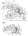
- Fig. 1 shows a schematic side view of a Kämmstelle, or a combing head of a comber, which was omitted for clarity reasons on the presentation of the pivot arms for the nipper unit Z, the brush roller for cleaning the combing cylinder 10 and the casing for the suction.
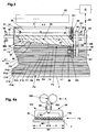
- the combing machine has a plurality of adjacent Kämmstellen, such as. B. from the top view Fig. 4 can be seen.
- Fig. 4 ten juxtaposed combing heads shown.
- a combing head of sixteen juxtaposed combing heads is shown, as can be seen from the number of slivers F1 to F16 (Fx) resting on the table T shown.
- Each combing head can be provided with a single drive unit, which are connected to a central control unit.
- the combing heads are driven together via corresponding drive means of a central drive.
- one of these combing points is shown and described in a schematic side view.
- nipper unit Z instead of the shown pivotable attachment of the nipper unit Z would also be conceivable to arrange the nipper unit ("pliers" for short) stationary, with, to form the nip KS, only the upper nipper knife 3 moves with respect to a fixed pliers plate 2.
- a reciprocating pliers Z (see double arrow) is assumed, wherein the drive for the oscillatory movement of a gear G is made, which is connected via the schematically illustrated drive path 8 with the pivot axis 4 of the frame R of the pliers Z.
- a rotatably mounted feed roller 5 is arranged, which is connected to an intermittent drive, not shown, and for the stepwise feeding of a cotton wool W (or slivers) to the clamping point KS of the forceps.
- the pliers Z is in a rear position and is closed.
- the end of the wadding projecting beyond the clamping point KS (fiber tuft FB) is combed out through the clothing of a combing segment 11, which extends over a partial region of the circumference of a combing cylinder 10.
- the combing cylinder 10 is rotatably mounted in the machine frame MS via the axis 13 and is driven by the gear G via the drive path 14 shown schematically.
- the drive of the transmission G is carried out by a schematically illustrated main motor M, which communicates with a control unit ST via the line 44 in connection.
- a tear-off segment 12 is mounted on the combing cylinder 10, which in cooperation with a slidably mounted Abrollwalze 15 (see double arrow) performs the demolition of the combed fiber tuft FB, as will be described below.
- a brush roller 72 is rotatably mounted below the combing cylinder 10 via an axis 73 in schematically illustrated bearing points 82 in the machine frame MS. The bristles of the brush roll protrude when passing the combing segment 11 into the clothing of the combing segment.
- the drive of the brush roller 72 is effected by a separate motor M1 via the drive connection 75.
- the motor M1 is connected to the control unit ST via the line 77.
- the power, or the torque of the shaft 73 may, for. B. via corresponding sensors (not shown) are monitored. With a wear of the bristles, the drive power to be applied, or also the applied torque for driving the brush roller 72 is reduced. This is monitored by the sensors already described and not shown, which transmit their signals via the line 76 to the control unit ST.
- the bearings of the axis 73 are slidably mounted in not shown guides in the machine frame MS. Thus, the cleaning action of the brush roller 72 is automatically maintained and controlled.
- this publication is to be taken from a corresponding embodiment of a screen drum, wherein within the screen drum still another, rotatably mounted cylinder is provided with openings to control the air flows during the tearing and soldering process.
- a simple screen drum 17 is shown, in the interior of which a stationary cover element 28 is arranged, which seals off the region of the screen drum, in which the fiber web V formed on the screen drum 17 is removed from the screen drum.
- the interior of the screen drum 17 is connected via the line 26 to a vacuum source 25, via which a negative pressure is generated within the screen drum.
- a pressure roller 30 is rotatably mounted, which z. B.
- the pressure roller may be mounted in corresponding guides in the machine frame MS in the direction of the circumferential surface of the screen drum.
- the bearing of the pressure roller is mounted in pivot arms whose pivot axes are axially parallel to the axis of the screen drum 17 and stored in the machine frame MS.
- the pressure roller 30, together with the screen drum 17, forms a nip 31 for the fiber web V guided between the screen drum and the pressure roller.
- the nip 31 extends over the width B of the fiber web V guided on the outer circumference U of the screen drum 17.
- the pressure roller can, for. B.
- a guide element 31 is attached downstream of the clamping point 31, via which the fiber fleece V (called “fleece” for short) is brought together laterally and delivered to a fleece funnel 39 ("hopper" for short).
- the sheet-like web V is combined to form a sliver F1, which is passed through the nip K K of a press roll pair K for further densification following the funnel 39.
- the Press roll pair is referred to in the following description as "Kalanderwalzencru K" with the calender rolls K1 and K2.
- the guide element 33 has a lower guide surface 37, which extends over a partial region of the circumference U of the sieve drum 17 and is adapted to the shape of the circumference of the sieve drum 17. Between the circumference U of the screen drum 17 and the guide surface 37 is only a small distance, which only ensures that the guide member 31 does not drag on the circumference U of the screen drum.
- the guide element 37 is fixedly connected to the machine frame MS via fastening elements, not shown, and is thus held in a fixed position relative to the circumferential surface U of the screening drum 17.
- the guide member 33 is provided with side guides 34 and 35, which are connected to the lower guide surface 37 and extending from this - with respect to the axis 18 of the screen drum 17 - to the outside ,
- the hopper 39 and the guide member 33 may be made in one piece with the hopper 39 provided with side guides 41, 42 extending downwardly. These side guides take over the lateral guidance of the combined in the hopper 39 sliver to the nip KK a subsequent Kalanderwalzencrues K.
- one of the calender rolls K1 of Kalanderwalzencrues K rotatably and coaxially mounted on the screen drum 17 and is located outside the area in which the web V extends with the width B in the feed to the nip 31.
- the second calender roll K2 is about the bearing L1 z. B.
- the calender roll K2 is driven by a drive wheel A2, which is in drive connection with the drive wheel A1 via a belt ZR (eg toothed belt).
- the belt ZR is tensioned by tensioners, not shown, to compensate for the movements between the axes of the calender rolls K1, K2. Also conceivable is the use of gear drives.
- the drive wheel A2 is rotatably mounted on the axis 29, which is fixedly connected to the calender roll K2.
- the axis 29 is, as schematically indicated, stored in the bearing point L1, which is located in the pivot arm 49.
- the drive wheel A1 is mounted on the axis 18 of the screen drum 17, which at the same time also represents the drive axis of the calender roll K1, since the calender roll is connected coaxially and fixedly to the screen drum 17.
- the axis 18 of the screening drum 17 is rotatably supported by the bearings 19, 20 in the machine frame MS.
- a further drive wheel A3 is rotatably mounted on the axis 18, which is connected via a schematically illustrated drive element AE with the gear G in drive connection.
- pivotally mounted guide elements FE are provided following the calender roller pairs K, via which the sliver (eg F1) delivered by the respective calender roller pair K is taken over and positioned on a subsequent conveyor table T.
- the delivery of the sliver F1 to the respective guide element FE takes place at the delivery point AG.
- the conveyor table T can consist of a fixed sliding surface or from a driven conveyor belt, such. B. in the Fig. 1 was indicated schematically.
- the fiber slivers F1 to Fx delivered on the conveyor table T are fed next to one another horizontally in a sliver composite to a following drafting system, in which the sliver composite is stretched and subsequently combined to form a single sliver.
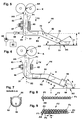
- the guide element FE consists of a tube 52 which is provided with two bends B1, B2.
- the tube 55 has on the end, which faces the calender rolls K, a funnel-shaped end portion (called "funnel 53" for short), which is to simplify the introduction of the sliver F1 in the guide element FE.
- the tube 55 is mounted in a bearing 60 and is thus mounted in a horizontal plane E about the pivot axis S1 parallel to the surface of the conveyor table T pivotally.
- the bearing 60 is mounted in the machine frame MS and is provided with a locking screw 57, via which the tube 52 of the guide element FE can be fixed in a set position.
- an outlet opening 51 is provided on the end of the tube 52, which ends in the region of the guide table T. The outlet opening 51 can thereby run at an acute angle ⁇ to the surface O of the transport table T.
- a tube 66 which is connected to a compressed air source 68 which is controlled by the control unit ST .
- a stream of compressed air By blowing a stream of compressed air through the pipe 66 (also called “injector") in the tube 52 is formed in the region of the funnel 53 and the bearing 60, a negative pressure in the tube 52, whereby a newly feeding after sliver F1 automatically retracted into the tube 52 and to the discharge port 51. If necessary, the supply of compressed air can be maintained throughout the operation to aid in the transport of the sliver within the tube 52.
- openings 70 may be provided on the circumference of the tube 52.
- a further embodiment of a guide element FE is shown, wherein a first tubular part 55, which is also provided at its one end with a funnel 53, is pivotally mounted in the machine frame MS via a bearing 62 in a horizontal plane about a pivot axis S2.
- a screw 57 To fix the set position is, as in the example of Fig. 5 , also provided a screw 57.
- an upwardly open channel 59 is fixed at the end of the tube 55 and is provided with a turn B2.
- ring 64 is provided, which is provided with an outlet opening 56 which points in the direction of the conveyor table.
- This outlet opening 56 may also be aligned at an acute angle ⁇ to the surface O of the conveyor table T. As in particular from the sectional view AA of Fig. 7 can be seen, is ensured by the completely closed ring 64 that the sliver in the region of the discharge opening 56 can not escape upwards and thus is discharged at an exact position AS on the conveyor table T.
- the ring 64 is not completely closed, and z. B. is designed as a slotted ring.
- the coverage by the slotted ring in the region of the opening of the guide channel must be chosen so large, so that a deflection of the sliver is prevented.
- the entrained air has the opportunity to escape upwards, so that this no disturbing influences on the transport of the sliver within of the guide element FE can exercise more.
- the entrained air can lead to compression of the fiber material within the tube by the entrained air.
- an exact storage location AS can be set on the conveyor table for the individual slivers F1 to Fx.
- the delivery points of the Kalanderwalzencrue K all lie on a same line L, whereby the individual combing heads can be made similar in relation to the arrangement of the calender rolls.
- the storage location AS on the conveyor table T is determined by the setting of the individual guide elements. It would also be conceivable to provide the tubes 52, 55 with markings, via which, in conjunction with further marking on the bearing 60, 62, or on the machine frame MS, corresponding positions can be set.
- the Fig. 4a shows an alternative embodiment with a partial view Q after Fig. 4 , wherein the delivery points AG of the respective Kalanderwalzencrue K (see dashed line K 'in Figure 4 ) lie in a line LM, which coincides with the center line MT of the conveyor table T.
- the conveyor table has a width BT and the line LM halves about this width, as shown schematically.
- the distance from the delivery point AG of the respective Kalanderwalzenpases K from the delivery point AS of the first sliver F1 on the conveyor table T and from the delivery point AS of the last sliver F10 (Fx) on the conveyor table T are kept the same.
- the required length of the guide elements FE can be kept short and a compact design can be achieved.
- Fig. 4a For example, only two of the guide elements FE, FE 'are shown, which are arranged pivotably about one axis S1.
- FIGS. 8 and 9 (according to the view Fig. 1 ) is shown schematically.
- Fig. 8 shows a previously common variant, wherein the individual slivers F1 to Fx on a level placed directly next to each other on the conveyor table and transported to the following drafting in a sliver composite.
- Fig. 9 shows a further variant, wherein the slivers F1 to Fx were placed in two levels E1 and E2 on the conveyor table.
- the slivers of the second plane E2 are offset by an offset a (diameter of a sliver) transversely to the conveying direction FT, or placed.
- a diameter of a sliver
- the filing of directly adjacent combing heads to be chosen so that the output of these slivers on the conveyor table does not come directly adjacent to the hang.
- z. B the slivers of Kämmkopfes K1 with the slivers of the combing heads K5 and K12 on the conveyor table T adjacent to each other adjacent to rest. That is, with this device can u.
- U the slivers of Kämmkopfes K1 with the slivers of the combing heads K5 and K12 on the conveyor table T adjacent to each other adjacent to rest. That is, with this device can u.
- U
- a better mixing of the fiber material of the individual combing heads can be achieved.
- a geometrically uniform guide element can be used on all combing heads. It is also an embodiment possible, wherein z.
- the delivery of the sliver of Kämmkopfes K1, which is located closest to the drafting D to make a fixed guide element and equip the other combing heads with an adjustable guide element In this case, further embodiments are possible.
- the pliers Z In the in Fig. 1 shown position, the pliers Z is closed and is in a rear position.
- the fiber beard FB protruding from the clamping point KS of the pliers Z is combed out by the comb segment 11 of the combing cylinder 10 in engagement.
- the flap 22 is located near the circumference U of the following screening drum 17, so that the combed out components (noils) are discharged downwards in a suction channel, not shown.
- the pliers Z moves in a front position and is now at a shorter distance to the tear roller 15, which in the meantime in the direction of the axis thirteenth the combing cylinder 10 has been moved and forms a nip with the tear-off segment 12.
- the tear-off segment 12 was moved by the rotational movement of the combing cylinder 10 during the forward movement of the pliers Z in the area below the tear-off roller 15.
- the area of the transfer, as well as the area above the sieve drum 17, can be provided with corresponding casings (not shown) in order to be able to precisely control the air flows which are necessary for the transfer and the soldering process.
- the screen drum 17 is driven at a constant speed and moves the web V on its circumference U to the nip 31 between the pressure roller 30 and the screen drum 17. After leaving the nip 31, the web V reaches the lower guide surface 37 of the guide member 33 and hits on the side guide 34, on which is transferred by the oblique arrangement of the straight portion 36 to the hopper 39.
- the arranged on the opposite side further side guide 35 with its straight gate 38 supports the transfer of the opposite web edge to the funnel 39th
- the fleece transferred to the hopper 39 is thereby combined and compacted and is transferred via the hopper to the nip KK of a following and driven calender roll pair K (K1, K2).
- This transfer is supported by the existing side guides 41, 42, which are attached to the hopper 39.
- a lateral deflection of the fiber material is prevented before it enters the terminal point KK, where it is further compressed.
- the fiber sliver F1 delivered by the calender rollers K1, K2 downwardly in the conveying direction FX is discharged into a funnel 53 of a pivotally arranged guide element FE and reaches a fixed or driven conveyor table T via a pipe 52 at a specific storage location AS the sliver F1 in the conveying direction FT with further slivers F2 to Fx, which were produced and discharged at adjacent Kämmstellen, transferred to a subsequent drafting unit D.
- a strip tray (not shown) may be provided to place the sliver formed on the drafting unit D in a pot.
- the table T can also be powered by a conveyor, z. B. consist of a conveyor belt. It can also be provided a much larger number of combing heads next to each other, as shown in the embodiments. Also, a number of up to 48 adjacent Kämmstellen is possible.
- the compressed air supply is interrupted again. If necessary, to assist the conveyance of the sliver F1 within the tube 52, the compressed air supply can be maintained even during operation at a reduced pressure. The supply of the slivers of adjacent Kämmkexcellent takes place accordingly.
- the fiber slivers F1 to Fx released in this form onto the conveyor table for the first time are made into a manually or by means of a driven conveyor table T Sliver bond (see Fig. 3 and Fig. 4 ) and fed to the input roller pair of the following drafting unit D or other possible funding aids.
- the structure of the fiber structure is controlled on the conveyor table T and optionally corrects the storage locations AS of the previously set guide elements FE.
- the screws 57 are loosened at the corresponding guide elements FE and their delivery point AS is corrected to the conveyor table T by pivoting the respective guide element about the axis S1.
- this position is fixed by tightening the screw 57.
- the machine can be started for operation.
- the embodiment of the guide element FE after the Fig. 6 with a compressed air supply 68, 66 according to the example Fig. 5 be equipped to perform an automatic threading can.
- the use of the automatic feed under the action of the compressed air source 68 is advantageous.
- the operation of the comber does not have to be interrupted.
- the missing sliver can be compensated by the use of a regulating device on the drafting unit D until a new sliver has been tracked.
- the use of the guiding elements proposed according to the invention makes it possible to individually design and influence the sliver composite fed to the following drafting system D and to correct it if necessary.
Landscapes
- Engineering & Computer Science (AREA)
- Textile Engineering (AREA)
- Preliminary Treatment Of Fibers (AREA)
Applications Claiming Priority (2)
| Application Number | Priority Date | Filing Date | Title |
|---|---|---|---|
| CH01553/09A CH702008A2 (de) | 2009-10-08 | 2009-10-08 | Kämmmaschine mit Faserbandführungsmittel. |
| PCT/CH2010/000241 WO2011041919A1 (de) | 2009-10-08 | 2010-10-04 | Kämmmaschine mit faserbandführungsmittel |
Publications (2)
| Publication Number | Publication Date |
|---|---|
| EP2486176A1 EP2486176A1 (de) | 2012-08-15 |
| EP2486176B1 true EP2486176B1 (de) | 2013-09-04 |
Family
ID=43478412
Family Applications (1)
| Application Number | Title | Priority Date | Filing Date |
|---|---|---|---|
| EP10767907.8A Not-in-force EP2486176B1 (de) | 2009-10-08 | 2010-10-04 | Kämmmaschine mit faserbandführungsmittel |
Country Status (5)
| Country | Link |
|---|---|
| EP (1) | EP2486176B1 (enExample) |
| JP (1) | JP2013507533A (enExample) |
| CN (1) | CN102549205B (enExample) |
| CH (1) | CH702008A2 (enExample) |
| WO (1) | WO2011041919A1 (enExample) |
Cited By (2)
| Publication number | Priority date | Publication date | Assignee | Title |
|---|---|---|---|---|
| EP2913428A1 (de) | 2014-02-27 | 2015-09-02 | Maschinenfabrik Rieter Ag | Kämmmaschine mit einer Vliesbildenden Vorrichtung |
| DE102020115191A1 (de) | 2020-06-08 | 2021-12-09 | Trützschler GmbH & Co Kommanditgesellschaft | Kämmmaschine |
Families Citing this family (2)
| Publication number | Priority date | Publication date | Assignee | Title |
|---|---|---|---|---|
| EP2354343B1 (de) | 2010-02-10 | 2014-07-23 | SPAETER Zug AG | Kragplattenanschlusselement / Druckelemente |
| DE102018122276B4 (de) * | 2018-09-12 | 2021-02-11 | TRüTZSCHLER GMBH & CO. KG | Kämmmaschine |
Family Cites Families (12)
| Publication number | Priority date | Publication date | Assignee | Title |
|---|---|---|---|---|
| JPS5112493Y1 (enExample) * | 1968-03-18 | 1976-04-05 | ||
| JPS513809B1 (enExample) * | 1968-08-14 | 1976-02-06 | ||
| GB1271316A (en) * | 1969-04-21 | 1972-04-19 | Osaka Kiko Kabushiki Kaisha | An improved method and apparatus for producing combed sliver |
| JPH0456768U (enExample) * | 1990-09-14 | 1992-05-15 | ||
| DE10127814A1 (de) * | 2001-06-07 | 2002-12-12 | Truetzschler Gmbh & Co Kg | Drehteller für Faserbandablageeinrichtungen, insbesondere an Strecken, Karden u. dgl. |
| CN2552957Y (zh) * | 2002-05-10 | 2003-05-28 | 郑伟东 | 一种精梳台面输出装置 |
| CN1510183A (zh) * | 2002-12-23 | 2004-07-07 | 倪 远 | 梳棉或精梳与并条工序联合的方法和设备 |
| DE102005001241A1 (de) | 2004-02-19 | 2005-09-01 | Maschinenfabrik Rieter Ag | Abzugswalzen einer Kämmmaschine |
| CN2813644Y (zh) * | 2005-08-09 | 2006-09-06 | 东台纺织机械有限责任公司 | 精梳机棉网导向装置 |
| EP2044249B1 (de) | 2006-07-25 | 2011-06-15 | Maschinenfabrik Rieter Ag | Kämmmaschine |
| WO2008011734A1 (de) * | 2006-07-25 | 2008-01-31 | Maschinenfabrik Rieter Ag | Kämmmaschine |
| DE102007045706A1 (de) * | 2007-09-24 | 2009-04-02 | TRüTZSCHLER GMBH & CO. KG | Kämmmaschine mit Kämmköpfen mit einem allen Kämmköpfen zugeordneten Streckwerk |
-
2009
- 2009-10-08 CH CH01553/09A patent/CH702008A2/de not_active Application Discontinuation
-
2010
- 2010-10-04 CN CN201080045250.7A patent/CN102549205B/zh not_active Expired - Fee Related
- 2010-10-04 EP EP10767907.8A patent/EP2486176B1/de not_active Not-in-force
- 2010-10-04 JP JP2012532436A patent/JP2013507533A/ja active Pending
- 2010-10-04 WO PCT/CH2010/000241 patent/WO2011041919A1/de not_active Ceased
Cited By (2)
| Publication number | Priority date | Publication date | Assignee | Title |
|---|---|---|---|---|
| EP2913428A1 (de) | 2014-02-27 | 2015-09-02 | Maschinenfabrik Rieter Ag | Kämmmaschine mit einer Vliesbildenden Vorrichtung |
| DE102020115191A1 (de) | 2020-06-08 | 2021-12-09 | Trützschler GmbH & Co Kommanditgesellschaft | Kämmmaschine |
Also Published As
| Publication number | Publication date |
|---|---|
| CN102549205A (zh) | 2012-07-04 |
| CN102549205B (zh) | 2015-03-25 |
| EP2486176A1 (de) | 2012-08-15 |
| JP2013507533A (ja) | 2013-03-04 |
| WO2011041919A1 (de) | 2011-04-14 |
| CH702008A2 (de) | 2011-04-15 |
Similar Documents
| Publication | Publication Date | Title |
|---|---|---|
| CH704348B1 (de) | Vorrichtung zur Fasersortierung bzw. -selektion eines Faserverbandes aus Textilfasern. | |
| EP2108720B1 (de) | Vorrichtung zur Bildung eines gekämmten Faservlieses | |
| DE102008004098A1 (de) | Vorrichtung zur Fasersortierung bzw. -selektion eines Faserverbandes aus Textilfasern, insbesondere zum Kämmen, der über Zuführmittel einer Fasersortiereinrichtung, insbesondere Kämmeinrichtung zugeführt wird | |
| EP1774072B1 (de) | Kämmmaschine. | |
| EP3514274B1 (de) | Getriebe mit einer einstellvorrichtung für eine kämmmaschine | |
| CH701944B1 (de) | Vorrichtung zur Fasersortierung bzw. -selektion eines Faserverbandes aus Textilfasern. | |
| EP2665850B1 (de) | Abdeckung bei einer kämmmaschine. | |
| EP3030702B1 (de) | Reinigungsvorrichtung für einen kämmzylinder einer kämmmaschine | |
| EP2486176B1 (de) | Kämmmaschine mit faserbandführungsmittel | |
| EP2044250B1 (de) | Kämmmaschine | |
| DE19713225B4 (de) | Abreiss- und Lötvorrichtung an einer Kämmaschine | |
| EP2044249B1 (de) | Kämmmaschine | |
| EP1774073B1 (de) | Kämmmaschine | |
| EP3207171B1 (de) | Absaugvorrichtung für eine kämmmaschine | |
| EP2452001B1 (de) | Vorrichtung zur bildung eines faserbandes | |
| EP1108076B1 (de) | Fasersortiereinrichtung | |
| DE102005001241A1 (de) | Abzugswalzen einer Kämmmaschine | |
| EP2791401B1 (de) | Kämmmaschine nach dem heilmann prinzip | |
| CH709311A2 (de) | Vorrichtung zur Bildung eines Faservlieses aus Faserpaketen. | |
| EP3514270A1 (de) | Antriebsvorrichtung für ein zangenaggregat einer kämmmaschine | |
| DE102008011546A1 (de) | Vorrichtung zur Fasersortierung bzw. -selektion eines Faserverbandes aus Textilfasern, insbesondere zum Kämmen |
Legal Events
| Date | Code | Title | Description |
|---|---|---|---|
| PUAI | Public reference made under article 153(3) epc to a published international application that has entered the european phase |
Free format text: ORIGINAL CODE: 0009012 |
|
| 17P | Request for examination filed |
Effective date: 20120427 |
|
| AK | Designated contracting states |
Kind code of ref document: A1 Designated state(s): AL AT BE BG CH CY CZ DE DK EE ES FI FR GB GR HR HU IE IS IT LI LT LU LV MC MK MT NL NO PL PT RO RS SE SI SK SM TR |
|
| DAX | Request for extension of the european patent (deleted) | ||
| GRAP | Despatch of communication of intention to grant a patent |
Free format text: ORIGINAL CODE: EPIDOSNIGR1 |
|
| INTG | Intention to grant announced |
Effective date: 20130402 |
|
| GRAS | Grant fee paid |
Free format text: ORIGINAL CODE: EPIDOSNIGR3 |
|
| GRAA | (expected) grant |
Free format text: ORIGINAL CODE: 0009210 |
|
| AK | Designated contracting states |
Kind code of ref document: B1 Designated state(s): AL AT BE BG CH CY CZ DE DK EE ES FI FR GB GR HR HU IE IS IT LI LT LU LV MC MK MT NL NO PL PT RO RS SE SI SK SM TR |
|
| REG | Reference to a national code |
Ref country code: GB Ref legal event code: FG4D Free format text: NOT ENGLISH |
|
| REG | Reference to a national code |
Ref country code: CH Ref legal event code: EP |
|
| REG | Reference to a national code |
Ref country code: AT Ref legal event code: REF Ref document number: 630612 Country of ref document: AT Kind code of ref document: T Effective date: 20130915 |
|
| REG | Reference to a national code |
Ref country code: IE Ref legal event code: FG4D Free format text: LANGUAGE OF EP DOCUMENT: GERMAN |
|
| REG | Reference to a national code |
Ref country code: DE Ref legal event code: R096 Ref document number: 502010004637 Country of ref document: DE Effective date: 20131024 |
|
| REG | Reference to a national code |
Ref country code: NL Ref legal event code: VDEP Effective date: 20130904 |
|
| PG25 | Lapsed in a contracting state [announced via postgrant information from national office to epo] |
Ref country code: SE Free format text: LAPSE BECAUSE OF FAILURE TO SUBMIT A TRANSLATION OF THE DESCRIPTION OR TO PAY THE FEE WITHIN THE PRESCRIBED TIME-LIMIT Effective date: 20130904 Ref country code: HR Free format text: LAPSE BECAUSE OF FAILURE TO SUBMIT A TRANSLATION OF THE DESCRIPTION OR TO PAY THE FEE WITHIN THE PRESCRIBED TIME-LIMIT Effective date: 20130904 Ref country code: LT Free format text: LAPSE BECAUSE OF FAILURE TO SUBMIT A TRANSLATION OF THE DESCRIPTION OR TO PAY THE FEE WITHIN THE PRESCRIBED TIME-LIMIT Effective date: 20130904 Ref country code: NO Free format text: LAPSE BECAUSE OF FAILURE TO SUBMIT A TRANSLATION OF THE DESCRIPTION OR TO PAY THE FEE WITHIN THE PRESCRIBED TIME-LIMIT Effective date: 20131204 Ref country code: CY Free format text: LAPSE BECAUSE OF FAILURE TO SUBMIT A TRANSLATION OF THE DESCRIPTION OR TO PAY THE FEE WITHIN THE PRESCRIBED TIME-LIMIT Effective date: 20130904 |
|
| REG | Reference to a national code |
Ref country code: NL Ref legal event code: VDEP Effective date: 20130904 |
|
| REG | Reference to a national code |
Ref country code: LT Ref legal event code: MG4D |
|
| PG25 | Lapsed in a contracting state [announced via postgrant information from national office to epo] |
Ref country code: LV Free format text: LAPSE BECAUSE OF FAILURE TO SUBMIT A TRANSLATION OF THE DESCRIPTION OR TO PAY THE FEE WITHIN THE PRESCRIBED TIME-LIMIT Effective date: 20130904 Ref country code: FI Free format text: LAPSE BECAUSE OF FAILURE TO SUBMIT A TRANSLATION OF THE DESCRIPTION OR TO PAY THE FEE WITHIN THE PRESCRIBED TIME-LIMIT Effective date: 20130904 Ref country code: GR Free format text: LAPSE BECAUSE OF FAILURE TO SUBMIT A TRANSLATION OF THE DESCRIPTION OR TO PAY THE FEE WITHIN THE PRESCRIBED TIME-LIMIT Effective date: 20131205 Ref country code: SI Free format text: LAPSE BECAUSE OF FAILURE TO SUBMIT A TRANSLATION OF THE DESCRIPTION OR TO PAY THE FEE WITHIN THE PRESCRIBED TIME-LIMIT Effective date: 20130904 Ref country code: PL Free format text: LAPSE BECAUSE OF FAILURE TO SUBMIT A TRANSLATION OF THE DESCRIPTION OR TO PAY THE FEE WITHIN THE PRESCRIBED TIME-LIMIT Effective date: 20130904 |
|
| BERE | Be: lapsed |
Owner name: MASCHINENFABRIK RIETER A.G. Effective date: 20131031 |
|
| PG25 | Lapsed in a contracting state [announced via postgrant information from national office to epo] |
Ref country code: NL Free format text: LAPSE BECAUSE OF FAILURE TO SUBMIT A TRANSLATION OF THE DESCRIPTION OR TO PAY THE FEE WITHIN THE PRESCRIBED TIME-LIMIT Effective date: 20130904 Ref country code: CZ Free format text: LAPSE BECAUSE OF FAILURE TO SUBMIT A TRANSLATION OF THE DESCRIPTION OR TO PAY THE FEE WITHIN THE PRESCRIBED TIME-LIMIT Effective date: 20130904 Ref country code: IS Free format text: LAPSE BECAUSE OF FAILURE TO SUBMIT A TRANSLATION OF THE DESCRIPTION OR TO PAY THE FEE WITHIN THE PRESCRIBED TIME-LIMIT Effective date: 20140104 Ref country code: RO Free format text: LAPSE BECAUSE OF FAILURE TO SUBMIT A TRANSLATION OF THE DESCRIPTION OR TO PAY THE FEE WITHIN THE PRESCRIBED TIME-LIMIT Effective date: 20130904 Ref country code: EE Free format text: LAPSE BECAUSE OF FAILURE TO SUBMIT A TRANSLATION OF THE DESCRIPTION OR TO PAY THE FEE WITHIN THE PRESCRIBED TIME-LIMIT Effective date: 20130904 Ref country code: SK Free format text: LAPSE BECAUSE OF FAILURE TO SUBMIT A TRANSLATION OF THE DESCRIPTION OR TO PAY THE FEE WITHIN THE PRESCRIBED TIME-LIMIT Effective date: 20130904 |
|
| PG25 | Lapsed in a contracting state [announced via postgrant information from national office to epo] |
Ref country code: ES Free format text: LAPSE BECAUSE OF FAILURE TO SUBMIT A TRANSLATION OF THE DESCRIPTION OR TO PAY THE FEE WITHIN THE PRESCRIBED TIME-LIMIT Effective date: 20130904 |
|
| REG | Reference to a national code |
Ref country code: DE Ref legal event code: R097 Ref document number: 502010004637 Country of ref document: DE |
|
| PG25 | Lapsed in a contracting state [announced via postgrant information from national office to epo] |
Ref country code: MC Free format text: LAPSE BECAUSE OF FAILURE TO SUBMIT A TRANSLATION OF THE DESCRIPTION OR TO PAY THE FEE WITHIN THE PRESCRIBED TIME-LIMIT Effective date: 20130904 Ref country code: PT Free format text: LAPSE BECAUSE OF FAILURE TO SUBMIT A TRANSLATION OF THE DESCRIPTION OR TO PAY THE FEE WITHIN THE PRESCRIBED TIME-LIMIT Effective date: 20140106 |
|
| PLBE | No opposition filed within time limit |
Free format text: ORIGINAL CODE: 0009261 |
|
| STAA | Information on the status of an ep patent application or granted ep patent |
Free format text: STATUS: NO OPPOSITION FILED WITHIN TIME LIMIT |
|
| REG | Reference to a national code |
Ref country code: IE Ref legal event code: MM4A |
|
| REG | Reference to a national code |
Ref country code: FR Ref legal event code: ST Effective date: 20140630 |
|
| 26N | No opposition filed |
Effective date: 20140605 |
|
| PG25 | Lapsed in a contracting state [announced via postgrant information from national office to epo] |
Ref country code: FR Free format text: LAPSE BECAUSE OF NON-PAYMENT OF DUE FEES Effective date: 20131104 |
|
| REG | Reference to a national code |
Ref country code: DE Ref legal event code: R097 Ref document number: 502010004637 Country of ref document: DE Effective date: 20140605 |
|
| PG25 | Lapsed in a contracting state [announced via postgrant information from national office to epo] |
Ref country code: BE Free format text: LAPSE BECAUSE OF NON-PAYMENT OF DUE FEES Effective date: 20131031 Ref country code: DK Free format text: LAPSE BECAUSE OF FAILURE TO SUBMIT A TRANSLATION OF THE DESCRIPTION OR TO PAY THE FEE WITHIN THE PRESCRIBED TIME-LIMIT Effective date: 20130904 |
|
| PG25 | Lapsed in a contracting state [announced via postgrant information from national office to epo] |
Ref country code: IE Free format text: LAPSE BECAUSE OF NON-PAYMENT OF DUE FEES Effective date: 20131004 |
|
| PG25 | Lapsed in a contracting state [announced via postgrant information from national office to epo] |
Ref country code: SM Free format text: LAPSE BECAUSE OF FAILURE TO SUBMIT A TRANSLATION OF THE DESCRIPTION OR TO PAY THE FEE WITHIN THE PRESCRIBED TIME-LIMIT Effective date: 20130904 |
|
| GBPC | Gb: european patent ceased through non-payment of renewal fee |
Effective date: 20141004 |
|
| PG25 | Lapsed in a contracting state [announced via postgrant information from national office to epo] |
Ref country code: MK Free format text: LAPSE BECAUSE OF FAILURE TO SUBMIT A TRANSLATION OF THE DESCRIPTION OR TO PAY THE FEE WITHIN THE PRESCRIBED TIME-LIMIT Effective date: 20130904 Ref country code: RS Free format text: LAPSE BECAUSE OF FAILURE TO SUBMIT A TRANSLATION OF THE DESCRIPTION OR TO PAY THE FEE WITHIN THE PRESCRIBED TIME-LIMIT Effective date: 20131204 Ref country code: LU Free format text: LAPSE BECAUSE OF NON-PAYMENT OF DUE FEES Effective date: 20131004 Ref country code: BG Free format text: LAPSE BECAUSE OF FAILURE TO SUBMIT A TRANSLATION OF THE DESCRIPTION OR TO PAY THE FEE WITHIN THE PRESCRIBED TIME-LIMIT Effective date: 20130904 Ref country code: GB Free format text: LAPSE BECAUSE OF NON-PAYMENT OF DUE FEES Effective date: 20141004 Ref country code: HU Free format text: LAPSE BECAUSE OF FAILURE TO SUBMIT A TRANSLATION OF THE DESCRIPTION OR TO PAY THE FEE WITHIN THE PRESCRIBED TIME-LIMIT; INVALID AB INITIO Effective date: 20101004 |
|
| PG25 | Lapsed in a contracting state [announced via postgrant information from national office to epo] |
Ref country code: MT Free format text: LAPSE BECAUSE OF FAILURE TO SUBMIT A TRANSLATION OF THE DESCRIPTION OR TO PAY THE FEE WITHIN THE PRESCRIBED TIME-LIMIT Effective date: 20130904 |
|
| PGFP | Annual fee paid to national office [announced via postgrant information from national office to epo] |
Ref country code: CH Payment date: 20151021 Year of fee payment: 6 |
|
| PG25 | Lapsed in a contracting state [announced via postgrant information from national office to epo] |
Ref country code: TR Free format text: LAPSE BECAUSE OF FAILURE TO SUBMIT A TRANSLATION OF THE DESCRIPTION OR TO PAY THE FEE WITHIN THE PRESCRIBED TIME-LIMIT Effective date: 20130904 |
|
| REG | Reference to a national code |
Ref country code: AT Ref legal event code: MM01 Ref document number: 630612 Country of ref document: AT Kind code of ref document: T Effective date: 20151004 |
|
| PGFP | Annual fee paid to national office [announced via postgrant information from national office to epo] |
Ref country code: DE Payment date: 20161020 Year of fee payment: 7 |
|
| PG25 | Lapsed in a contracting state [announced via postgrant information from national office to epo] |
Ref country code: AT Free format text: LAPSE BECAUSE OF NON-PAYMENT OF DUE FEES Effective date: 20151004 |
|
| PGFP | Annual fee paid to national office [announced via postgrant information from national office to epo] |
Ref country code: IT Payment date: 20161024 Year of fee payment: 7 |
|
| REG | Reference to a national code |
Ref country code: CH Ref legal event code: PL |
|
| PG25 | Lapsed in a contracting state [announced via postgrant information from national office to epo] |
Ref country code: LI Free format text: LAPSE BECAUSE OF NON-PAYMENT OF DUE FEES Effective date: 20161031 Ref country code: CH Free format text: LAPSE BECAUSE OF NON-PAYMENT OF DUE FEES Effective date: 20161031 |
|
| REG | Reference to a national code |
Ref country code: DE Ref legal event code: R119 Ref document number: 502010004637 Country of ref document: DE |
|
| PG25 | Lapsed in a contracting state [announced via postgrant information from national office to epo] |
Ref country code: DE Free format text: LAPSE BECAUSE OF NON-PAYMENT OF DUE FEES Effective date: 20180501 |
|
| PG25 | Lapsed in a contracting state [announced via postgrant information from national office to epo] |
Ref country code: IT Free format text: LAPSE BECAUSE OF NON-PAYMENT OF DUE FEES Effective date: 20171004 Ref country code: AL Free format text: LAPSE BECAUSE OF FAILURE TO SUBMIT A TRANSLATION OF THE DESCRIPTION OR TO PAY THE FEE WITHIN THE PRESCRIBED TIME-LIMIT Effective date: 20130904 |