EP2485312A1 - Redox-flussbatterie - Google Patents
Redox-flussbatterie Download PDFInfo
- Publication number
- EP2485312A1 EP2485312A1 EP11775037A EP11775037A EP2485312A1 EP 2485312 A1 EP2485312 A1 EP 2485312A1 EP 11775037 A EP11775037 A EP 11775037A EP 11775037 A EP11775037 A EP 11775037A EP 2485312 A1 EP2485312 A1 EP 2485312A1
- Authority
- EP
- European Patent Office
- Prior art keywords
- ion
- redox potential
- electrolyte
- negative electrode
- positive electrode
- Prior art date
- Legal status (The legal status is an assumption and is not a legal conclusion. Google has not performed a legal analysis and makes no representation as to the accuracy of the status listed.)
- Granted
Links
- 239000003792 electrolyte Substances 0.000 claims abstract description 209
- 229910021645 metal ion Inorganic materials 0.000 claims abstract description 163
- WAEMQWOKJMHJLA-UHFFFAOYSA-N Manganese(2+) Chemical compound [Mn+2] WAEMQWOKJMHJLA-UHFFFAOYSA-N 0.000 claims abstract description 48
- 229910001437 manganese ion Inorganic materials 0.000 claims abstract description 44
- 229910001430 chromium ion Inorganic materials 0.000 claims abstract description 34
- -1 vanadium (V) ion Chemical class 0.000 claims abstract description 6
- 229910001456 vanadium ion Inorganic materials 0.000 claims description 173
- QAOWNCQODCNURD-UHFFFAOYSA-N Sulfuric acid Chemical compound OS(O)(=O)=O QAOWNCQODCNURD-UHFFFAOYSA-N 0.000 claims description 59
- 239000007864 aqueous solution Substances 0.000 claims description 23
- 239000011572 manganese Substances 0.000 claims description 12
- PWHULOQIROXLJO-UHFFFAOYSA-N Manganese Chemical compound [Mn] PWHULOQIROXLJO-UHFFFAOYSA-N 0.000 claims description 10
- 229910052748 manganese Inorganic materials 0.000 claims description 10
- PTFCDOFLOPIGGS-UHFFFAOYSA-N Zinc dication Chemical compound [Zn+2] PTFCDOFLOPIGGS-UHFFFAOYSA-N 0.000 claims description 7
- 239000002904 solvent Substances 0.000 claims description 7
- QAOWNCQODCNURD-UHFFFAOYSA-L Sulfate Chemical compound [O-]S([O-])(=O)=O QAOWNCQODCNURD-UHFFFAOYSA-L 0.000 claims description 6
- RVPVRDXYQKGNMQ-UHFFFAOYSA-N lead(2+) Chemical compound [Pb+2] RVPVRDXYQKGNMQ-UHFFFAOYSA-N 0.000 claims description 4
- 229910052684 Cerium Inorganic materials 0.000 claims description 3
- 229910001429 cobalt ion Inorganic materials 0.000 claims 2
- XLJKHNWPARRRJB-UHFFFAOYSA-N cobalt(2+) Chemical compound [Co+2] XLJKHNWPARRRJB-UHFFFAOYSA-N 0.000 claims 2
- WPBNNNQJVZRUHP-UHFFFAOYSA-L manganese(2+);methyl n-[[2-(methoxycarbonylcarbamothioylamino)phenyl]carbamothioyl]carbamate;n-[2-(sulfidocarbothioylamino)ethyl]carbamodithioate Chemical compound [Mn+2].[S-]C(=S)NCCNC([S-])=S.COC(=O)NC(=S)NC1=CC=CC=C1NC(=S)NC(=O)OC WPBNNNQJVZRUHP-UHFFFAOYSA-L 0.000 claims 1
- 238000007086 side reaction Methods 0.000 abstract description 37
- 238000007254 oxidation reaction Methods 0.000 abstract description 21
- 239000011149 active material Substances 0.000 abstract description 20
- 150000002500 ions Chemical class 0.000 abstract description 16
- UFHFLCQGNIYNRP-UHFFFAOYSA-N Hydrogen Chemical compound [H][H] UFHFLCQGNIYNRP-UHFFFAOYSA-N 0.000 abstract description 15
- MYMOFIZGZYHOMD-UHFFFAOYSA-N Dioxygen Chemical compound O=O MYMOFIZGZYHOMD-UHFFFAOYSA-N 0.000 abstract description 12
- 229910001882 dioxygen Inorganic materials 0.000 abstract description 12
- 238000000354 decomposition reaction Methods 0.000 abstract description 7
- XLYOFNOQVPJJNP-UHFFFAOYSA-N water Substances O XLYOFNOQVPJJNP-UHFFFAOYSA-N 0.000 abstract description 7
- 230000003647 oxidation Effects 0.000 abstract description 6
- 230000015556 catabolic process Effects 0.000 abstract description 4
- 238000006731 degradation reaction Methods 0.000 abstract description 4
- 230000002708 enhancing effect Effects 0.000 abstract 1
- 238000006243 chemical reaction Methods 0.000 description 19
- 238000006722 reduction reaction Methods 0.000 description 17
- LEONUFNNVUYDNQ-UHFFFAOYSA-N vanadium atom Chemical compound [V] LEONUFNNVUYDNQ-UHFFFAOYSA-N 0.000 description 17
- NUJOXMJBOLGQSY-UHFFFAOYSA-N manganese dioxide Chemical compound O=[Mn]=O NUJOXMJBOLGQSY-UHFFFAOYSA-N 0.000 description 14
- 229910052720 vanadium Inorganic materials 0.000 description 12
- 150000003467 sulfuric acid derivatives Chemical class 0.000 description 11
- VLOPEOIIELCUML-UHFFFAOYSA-L vanadium(2+);sulfate Chemical compound [V+2].[O-]S([O-])(=O)=O VLOPEOIIELCUML-UHFFFAOYSA-L 0.000 description 10
- 238000010248 power generation Methods 0.000 description 9
- 230000000694 effects Effects 0.000 description 8
- 239000012528 membrane Substances 0.000 description 8
- OKTJSMMVPCPJKN-UHFFFAOYSA-N Carbon Chemical compound [C] OKTJSMMVPCPJKN-UHFFFAOYSA-N 0.000 description 7
- 239000002253 acid Substances 0.000 description 7
- 229910052799 carbon Inorganic materials 0.000 description 7
- 239000007788 liquid Substances 0.000 description 7
- 230000001629 suppression Effects 0.000 description 6
- VYZAMTAEIAYCRO-UHFFFAOYSA-N Chromium Chemical compound [Cr] VYZAMTAEIAYCRO-UHFFFAOYSA-N 0.000 description 5
- 239000003575 carbonaceous material Substances 0.000 description 5
- 229940099596 manganese sulfate Drugs 0.000 description 5
- 235000007079 manganese sulphate Nutrition 0.000 description 5
- 239000011702 manganese sulphate Substances 0.000 description 5
- SQQMAOCOWKFBNP-UHFFFAOYSA-L manganese(II) sulfate Chemical compound [Mn+2].[O-]S([O-])(=O)=O SQQMAOCOWKFBNP-UHFFFAOYSA-L 0.000 description 5
- 238000006479 redox reaction Methods 0.000 description 5
- 230000009467 reduction Effects 0.000 description 5
- 239000011701 zinc Substances 0.000 description 5
- 239000011651 chromium Substances 0.000 description 4
- GRWVQDDAKZFPFI-UHFFFAOYSA-H chromium(III) sulfate Chemical compound [Cr+3].[Cr+3].[O-]S([O-])(=O)=O.[O-]S([O-])(=O)=O.[O-]S([O-])(=O)=O GRWVQDDAKZFPFI-UHFFFAOYSA-H 0.000 description 4
- 230000003247 decreasing effect Effects 0.000 description 4
- 239000007772 electrode material Substances 0.000 description 4
- 239000001257 hydrogen Substances 0.000 description 4
- 229910052739 hydrogen Inorganic materials 0.000 description 4
- 239000003014 ion exchange membrane Substances 0.000 description 4
- NHNBFGGVMKEFGY-UHFFFAOYSA-N Nitrate Chemical compound [O-][N+]([O-])=O NHNBFGGVMKEFGY-UHFFFAOYSA-N 0.000 description 3
- 229910019142 PO4 Inorganic materials 0.000 description 3
- 229910052804 chromium Inorganic materials 0.000 description 3
- 230000006866 deterioration Effects 0.000 description 3
- 238000007323 disproportionation reaction Methods 0.000 description 3
- 230000006872 improvement Effects 0.000 description 3
- 238000001556 precipitation Methods 0.000 description 3
- 230000009257 reactivity Effects 0.000 description 3
- 230000002441 reversible effect Effects 0.000 description 3
- 239000000243 solution Substances 0.000 description 3
- HCHKCACWOHOZIP-UHFFFAOYSA-N Zinc Chemical compound [Zn] HCHKCACWOHOZIP-UHFFFAOYSA-N 0.000 description 2
- 230000008859 change Effects 0.000 description 2
- 239000000463 material Substances 0.000 description 2
- 229910052751 metal Inorganic materials 0.000 description 2
- 239000002184 metal Substances 0.000 description 2
- 239000007773 negative electrode material Substances 0.000 description 2
- 230000033116 oxidation-reduction process Effects 0.000 description 2
- 239000010452 phosphate Substances 0.000 description 2
- 239000007774 positive electrode material Substances 0.000 description 2
- 229910052725 zinc Inorganic materials 0.000 description 2
- KZBUYRJDOAKODT-UHFFFAOYSA-N Chlorine Chemical compound ClCl KZBUYRJDOAKODT-UHFFFAOYSA-N 0.000 description 1
- 229910002651 NO3 Inorganic materials 0.000 description 1
- QVGXLLKOCUKJST-UHFFFAOYSA-N atomic oxygen Chemical compound [O] QVGXLLKOCUKJST-UHFFFAOYSA-N 0.000 description 1
- GWXLDORMOJMVQZ-UHFFFAOYSA-N cerium Chemical compound [Ce] GWXLDORMOJMVQZ-UHFFFAOYSA-N 0.000 description 1
- 239000002800 charge carrier Substances 0.000 description 1
- 229910017052 cobalt Inorganic materials 0.000 description 1
- 239000010941 cobalt Substances 0.000 description 1
- GUTLYIVDDKVIGB-UHFFFAOYSA-N cobalt atom Chemical compound [Co] GUTLYIVDDKVIGB-UHFFFAOYSA-N 0.000 description 1
- 230000003750 conditioning effect Effects 0.000 description 1
- 239000000470 constituent Substances 0.000 description 1
- 230000007547 defect Effects 0.000 description 1
- 230000005611 electricity Effects 0.000 description 1
- 238000002474 experimental method Methods 0.000 description 1
- 239000012530 fluid Substances 0.000 description 1
- 238000009499 grossing Methods 0.000 description 1
- 230000009931 harmful effect Effects 0.000 description 1
- IXCSERBJSXMMFS-UHFFFAOYSA-N hcl hcl Chemical compound Cl.Cl IXCSERBJSXMMFS-UHFFFAOYSA-N 0.000 description 1
- 238000009434 installation Methods 0.000 description 1
- 238000002955 isolation Methods 0.000 description 1
- YADSGOSSYOOKMP-UHFFFAOYSA-N lead dioxide Inorganic materials O=[Pb]=O YADSGOSSYOOKMP-UHFFFAOYSA-N 0.000 description 1
- 230000007774 longterm Effects 0.000 description 1
- 230000007246 mechanism Effects 0.000 description 1
- 239000000203 mixture Substances 0.000 description 1
- 239000001301 oxygen Substances 0.000 description 1
- 229910052760 oxygen Inorganic materials 0.000 description 1
- 230000035699 permeability Effects 0.000 description 1
- 239000012466 permeate Substances 0.000 description 1
- 230000002265 prevention Effects 0.000 description 1
- 239000007787 solid Substances 0.000 description 1
- 230000000087 stabilizing effect Effects 0.000 description 1
- 238000010792 warming Methods 0.000 description 1
Images


Classifications
-
- H—ELECTRICITY
- H01—ELECTRIC ELEMENTS
- H01M—PROCESSES OR MEANS, e.g. BATTERIES, FOR THE DIRECT CONVERSION OF CHEMICAL ENERGY INTO ELECTRICAL ENERGY
- H01M8/00—Fuel cells; Manufacture thereof
- H01M8/18—Regenerative fuel cells, e.g. redox flow batteries or secondary fuel cells
- H01M8/184—Regeneration by electrochemical means
- H01M8/188—Regeneration by electrochemical means by recharging of redox couples containing fluids; Redox flow type batteries
-
- H—ELECTRICITY
- H01—ELECTRIC ELEMENTS
- H01M—PROCESSES OR MEANS, e.g. BATTERIES, FOR THE DIRECT CONVERSION OF CHEMICAL ENERGY INTO ELECTRICAL ENERGY
- H01M50/00—Constructional details or processes of manufacture of the non-active parts of electrochemical cells other than fuel cells, e.g. hybrid cells
- H01M50/70—Arrangements for stirring or circulating the electrolyte
- H01M50/77—Arrangements for stirring or circulating the electrolyte with external circulating path
-
- H—ELECTRICITY
- H01—ELECTRIC ELEMENTS
- H01M—PROCESSES OR MEANS, e.g. BATTERIES, FOR THE DIRECT CONVERSION OF CHEMICAL ENERGY INTO ELECTRICAL ENERGY
- H01M8/00—Fuel cells; Manufacture thereof
- H01M8/18—Regenerative fuel cells, e.g. redox flow batteries or secondary fuel cells
-
- H—ELECTRICITY
- H01—ELECTRIC ELEMENTS
- H01M—PROCESSES OR MEANS, e.g. BATTERIES, FOR THE DIRECT CONVERSION OF CHEMICAL ENERGY INTO ELECTRICAL ENERGY
- H01M8/00—Fuel cells; Manufacture thereof
- H01M8/02—Details
-
- H—ELECTRICITY
- H01—ELECTRIC ELEMENTS
- H01M—PROCESSES OR MEANS, e.g. BATTERIES, FOR THE DIRECT CONVERSION OF CHEMICAL ENERGY INTO ELECTRICAL ENERGY
- H01M2300/00—Electrolytes
- H01M2300/0088—Composites
-
- H—ELECTRICITY
- H01—ELECTRIC ELEMENTS
- H01M—PROCESSES OR MEANS, e.g. BATTERIES, FOR THE DIRECT CONVERSION OF CHEMICAL ENERGY INTO ELECTRICAL ENERGY
- H01M2300/00—Electrolytes
- H01M2300/0088—Composites
- H01M2300/0091—Composites in the form of mixtures
-
- Y—GENERAL TAGGING OF NEW TECHNOLOGICAL DEVELOPMENTS; GENERAL TAGGING OF CROSS-SECTIONAL TECHNOLOGIES SPANNING OVER SEVERAL SECTIONS OF THE IPC; TECHNICAL SUBJECTS COVERED BY FORMER USPC CROSS-REFERENCE ART COLLECTIONS [XRACs] AND DIGESTS
- Y02—TECHNOLOGIES OR APPLICATIONS FOR MITIGATION OR ADAPTATION AGAINST CLIMATE CHANGE
- Y02E—REDUCTION OF GREENHOUSE GAS [GHG] EMISSIONS, RELATED TO ENERGY GENERATION, TRANSMISSION OR DISTRIBUTION
- Y02E60/00—Enabling technologies; Technologies with a potential or indirect contribution to GHG emissions mitigation
- Y02E60/10—Energy storage using batteries
-
- Y—GENERAL TAGGING OF NEW TECHNOLOGICAL DEVELOPMENTS; GENERAL TAGGING OF CROSS-SECTIONAL TECHNOLOGIES SPANNING OVER SEVERAL SECTIONS OF THE IPC; TECHNICAL SUBJECTS COVERED BY FORMER USPC CROSS-REFERENCE ART COLLECTIONS [XRACs] AND DIGESTS
- Y02—TECHNOLOGIES OR APPLICATIONS FOR MITIGATION OR ADAPTATION AGAINST CLIMATE CHANGE
- Y02E—REDUCTION OF GREENHOUSE GAS [GHG] EMISSIONS, RELATED TO ENERGY GENERATION, TRANSMISSION OR DISTRIBUTION
- Y02E60/00—Enabling technologies; Technologies with a potential or indirect contribution to GHG emissions mitigation
- Y02E60/30—Hydrogen technology
- Y02E60/50—Fuel cells
Definitions
- the present invention relates to a redox flow battery containing a vanadium ion as active material, and particularly to a redox flow battery capable of improving an energy density as compared to the conventional vanadium redox flow battery.
- a redox flow battery is one of large-capacity storage batteries.
- a positive electrode electrolyte and a negative electrode electrolyte are supplied to a battery cell having a membrane interposed between a positive electrode and a negative electrode, to charge and discharge the battery.
- An aqueous solution containing a water-soluble metal ion having a valence which changes by oxidation-reduction is representatively used as the electrolytes, and such a metal ion is used as active material.
- the most widely studied type is a vanadium redox flow battery in which a vanadium (V) ion is used as active material for each of the positive electrode and the negative electrode (for example, Patent Literatures 1 and 2).
- the vanadium redox flow battery is currently put in practical use and expected to be continuously used in the future.
- batteries are desired to have a higher energy density.
- the above-described utilization rate means the actually available battery capacity (discharge capacity) with respect to the theoretical battery capacity (Ah) of the above-mentioned metal ion, that is, the difference between the battery capacity in the lower limit state of charge (SOC) and the battery capacity in the upper limit state of charge.
- the positive electrode undergoes a side reaction such as generation of oxygen resulting from water decomposition and deterioration of electrodes (particularly, made of carbon materials) while the negative electrode undergoes a side reaction such as generation of hydrogen resulting from water decomposition since an aqueous solution is utilized for an electrolyte as described above in the typical configuration of the redox flow battery.
- Patent Literature 1 proposes that a pentavalent V ion in the positive active material is 90% or less at the end of charge while Patent Literature 2 proposes that charge is to be continued such that a divalent V ion in the negative active material is 94% or less.
- the cell resistance is increased in the long-term use. Accordingly, when the voltage at which charge is to be stopped is set at a constant value without being changed from the beginning of its use, the cell resistance is increased, so that the state of charge at the start of its use cannot be maintained. Therefore, the voltage at which charge is stopped is to be increased over time in order to ensure a prescribed state of charge. Consequently, it becomes difficult to ensure a high state of charge without generating oxygen gas and hydrogen gas for a long period of time.
- An object of the present invention is to provide a redox flow battery that can improve an energy density.
- the present inventors have surprisingly found that the utilization rate of a vanadium ion can be greatly improved as compared to the conventional vanadium redox flow battery, for example, by causing the electrolyte containing a vanadium ion as active material to contain metal ions such as a manganese (Mn) ion that is higher in oxidation-reduction potential (hereinafter simply referred to as potential) than the vanadium ion on the positive electrode side and a metal ion such as a chromium (Cr) ion that exhibits a lower redox potential than the vanadium ion on the negative electrode side, together with the vanadium ion.
- Mn manganese
- Cr chromium
- the following side reaction may occur in the late stage of charge. Also shown in this case is the standard potential at the time of occurrence of each reaction when the electrode made of carbon material is utilized.
- an overvoltage depending on the used electrode material is required, in which case the potential at the time of occurrence of the actual side reaction on the positive electrode side tends to be higher than the standard value.
- the electrode material is carbon material
- the potential at the time of carbon reaction or water decomposition is about 2V, which is higher than about 1V that is the potential at the time of occurrence of battery reaction in the positive electrode. Therefore, an oxidation reaction of a vanadium ion (V 4+ ⁇ V 5+ ) mainly occurs in the positive electrode during charge as described above.
- the potential at the time of occurrence of the actual side reaction on the negative electrode side tends to be lower than the standard value, depending on the used electrode material.
- the electrode material is carbon material
- a hydrogen overvoltage is relatively large, with the result that the potential at the time of generation of hydrogen is approximately ⁇ 0.5V, which further exhibits a lower redox potential than approximately ⁇ 0.26V that is the potential at the time of occurrence of the battery reaction in the negative electrode. Therefore, during charge, a reduction reaction of the vanadium ion (V 3+ ⁇ V 2+ ) mainly occurs as described above in the negative electrode.
- hydrogen gas may be generated simultaneously with the above-described reduction reaction of the vanadium ion.
- the positive electrode electrolyte contains, in addition to a vanadium ion, a metal ion higher in redox potential than a vanadium ion.
- the potential of Mn 2+ /Mn 3+ is approximately 1.5V, which is higher than the potential of V 4+ /V 5+ (approximately 1.0V).
- this potential exists on the lower side with respect to the actual potential (approximately 2V) at the time of occurrence of a side reaction on the positive electrode side such as generation of oxygen gas resulting from water decomposition or electrode oxidation as described above.
- an oxidation reaction of Mn 2+ is to first occur before occurrence of the side reaction on the positive electrode side such as generation of oxygen gas described above.
- an oxidation reaction of Mn 2+ also occurs as a part of the battery reaction.
- the oxidation reaction of the metal ion different from the vanadium ion occurs, so that the above-described side reaction on the positive electrode side can be suppressed.
- the negative electrode electrolyte contains, in addition to a vanadium ion, a metal ion lower in redox potential than the vanadium ion.
- the potential of Cr 3+ /Cr 2+ is approximately ⁇ 0.42V that is lower than the potential of V 3+ /V 2+ (approximately ⁇ 0.26V).
- this potential exists on the higher side with respect to the actual potential (approximately ⁇ 0.5V) at the time of occurrence of the side reaction on the negative electrode side such as generation of hydrogen gas described above.
- a reduction reaction of Cr 3+ is to first occur before occurrence of the above-described side reaction on the negative electrode side.
- reduction reaction of Cr 3+ also occurs as part of the battery reaction.
- the reduction reaction of the metal ion different from the vanadium ion occurs, so that the above-described side reaction on the negative electrode side can be suppressed.
- the positive electrode electrolyte contains not only a vanadium ion but also a metal ion higher in redox potential than the vanadium ion
- the negative electrode electrolyte contains not only a vanadium ion but also a metal ion lower in redox potential than the vanadium ion
- the above-described side reaction hardly occurs or substantially does not occur, for example, even when charge is performed such that the state of charge of the electrolyte in each of the positive electrode and the negative electrode exceeds 90%.
- the vanadium ion in the electrolyte can be fully utilized repeatedly with stability as compared to the conventional vanadium redox flow battery.
- the utilization rate of the vanadium ion is enhanced in this way, thereby allowing improvement in the energy density.
- the present invention is based on the above-described findings.
- the present invention relates to a redox flow battery performing charge and discharge by supplying a positive electrode electrolyte and a negative electrode electrolyte to a battery cell.
- Each of the positive electrode electrolyte and the negative electrode electrolyte contains a vanadium ion.
- at least one of the positive electrode electrolyte and the negative electrode electrolyte further contains at least one of a metal ion higher in redox potential than a vanadium ion and a metal ion lower in redox potential than the vanadium ion.
- the redox flow battery according to the present invention having the above-described configuration allows suppression of the side reaction in the late stage of charge even when charge is performed until the state of charge of the electrolyte in at least one of the positive electrode and the negative electrode reaches nearly 100%.
- oxidation of another metal ion specifically, a metal ion higher in redox potential than a vanadium ion on the positive electrode side
- a vanadium ion allows suppression of the side reaction such as generation of oxygen gas resulting from water decomposition and oxidation degradation of the electrode as described above.
- the redox flow battery according to the present invention can raise the state of charge of the electrolyte in at least one of the electrodes to nearly 100%. The state of charge can be raised in this way, thereby allowing an increase in the utilization rate of the vanadium ion in the electrolyte. Accordingly, the redox flow battery according to the present invention can improve the energy density as compared to the conventional case.
- the redox flow battery according to the present invention can suppress the side reaction as described above, it can also effectively suppress various defects (decreased battery efficiency, decreased battery capacity, shortened lifetime) caused by the side reaction.
- the redox flow battery according to the present invention is not only excellent in battery characteristics but also capable of increasing the durability, high reliability can be ensured for a long period of time.
- a metal ion higher in redox potential than a vanadium ion exists at least in the positive electrode electrolyte
- a metal ion lower in redox potential than a vanadium ion exists at least in the negative electrode electrolyte, so that the side reaction in the late stage of charge can be effectively suppressed as described above, thereby allowing an increase in the utilization rate of the vanadium ion.
- At least the positive electrode electrolyte further contains a metal ion higher in redox potential than the vanadium ion while at least the negative electrode electrolyte further contains a metal ion lower in redox potential than the vanadium ion, since the side reaction in the late stage of charge described above is further effectively suppressed, thereby allowing a further increase in the utilization rate of the vanadium ion.
- This embodiment can also be configured such that the positive electrode electrolyte further contains a metal ion lower in redox potential than the vanadium ion or such that the negative electrode electrolyte further contains a metal ion higher in redox potential than the vanadium ion.
- the electrolyte in each of the positive electrode and the negative electrode contains a vanadium ion, a metal ion higher in redox potential than the vanadium ion and a metal ion lower in redox potential than the vanadium ion, and representatively, the embodiment in which the electrolytes in both of the electrodes contain the same metal ion species.
- metal ion species in the both positive and negative electrode electrolytes are the same or partially the same, specific effects as described below may be achieved.
- the metal ion higher in redox potential in the positive electrode electrolyte and the metal ion lower in redox potential in the negative electrode electrolyte each move to a counter electrode, to cause a relative decrease in the metal ion essentially reacting on each electrode, so that it becomes possible to effectively avoid or suppress a decreased effect of suppressing the side reaction.
- charge/discharge the phenomenon in which the electrolyte in one electrode moves to the other electrode
- mixture of the electrolytes in both of the electrodes allows or facilitates the variations to be readily corrected.
- Manufacturability of the electrolyte is excellent.
- the metal ion higher in redox potential than the vanadium ion existing in the negative electrode electrolyte and the metal ion lower in redox potential than the vanadium ion existing in the positive electrode electrolyte exist mainly for the electrolytes in both of the electrodes to contain partially the same metal ion species, but do not actively act as active materials.
- the concentration of the metal ion higher in redox potential in the negative electrode electrolyte and the concentration of the metal ion higher in redox potential in the positive electrode electrolyte may be differently set, and the concentration of the metal ion lower in redox potential in the positive electrode electrolyte and the concentration of the metal ion lower in redox potential in the negative electrode electrolyte may be differently set.
- these respective concentrations are equally set, the above-described effects (1) to (3) can be readily achieved.
- the above-described metal ion higher in redox potential and the above-described metal ion lower in redox potential are water-soluble similarly to a vanadium ion or soluble in an acid aqueous solution. It is preferable that the metal ion higher in redox potential exists on the lower side than the actual potential (approximately 2V) at the time when a side reaction occurs on the positive electrode side. It is preferable that the metal ion lower in redox potential exists on the higher side than the actual potential (approximately ⁇ 0.5V) at the time when a side reaction occurs on the negative electrode side.
- Examples of the above-described metal ion higher in redox potential may include at least one type of metal ions, for example, selected from a manganese (Mn) ion, a lead (Pb) ion, a cerium (Ce) ion, and a cobalt (Co) ion.
- the standard potential of the above-described metal ions is Mn 2+ /Mn 3+ : approximately 1.5V, Pb 2+ /Pb 4+ : approximately 1.62V, Pb 2+ /PbO 2 : approximately 1.69V, Ce 3+ /Ce 4+ : approximately 1.7V, and CO 2+ /CO 3+ : approximately 1.82V.
- this potential is higher than the potential of the vanadium ion on the positive electrode side: V 4+ /V 5+ (approximately 1.0V), and lower than the potential of the above-described side reaction on the positive electrode side (approximately 2V).
- the electrolyte in each of the positive electrode and the negative electrode may contain one type of the above-described higher potential metal ion or contain a plurality of types of combined higher potential metal ions having different potentials.
- Examples of the above-described metal ion lower in redox potential may include at least one type of metal ions, for example, of a chromium ion and a zinc ion.
- the standard potential of chromium is Cr 3+ / Cr 2+ : approximately ⁇ 0.42V, which is lower than the potential of the vanadium ion on the negative electrode side: V 3+ /V 2+ (approximately ⁇ 0.26V) and higher than the potential of the above-described side reaction on the negative electrode side (approximately ⁇ 0.5V).
- the standard potential of zinc is Zn 2+ /Zn (metal): approximately ⁇ 0.76V, which is lower than the potential of V 3+ /V 2+ (approximately ⁇ 0.26V) and lower than the potential of the above-described side reaction on the negative electrode side.
- zinc is sufficiently high in hydrogen overvoltage, and therefore, can cause a battery reaction.
- the electrolyte in each of the positive electrode and the negative electrode may contain one type of the above-described lower potential metal ion or contain a plurality of types of combined lower potential metal ions having different potentials.
- metal ions used as active material can be stabilized and supplied less expensively.
- Mn 3+ produced by oxidation reaction of Mn 2+ undergoes a reversible oxidation-reduction reaction in the sulfuric acid solution, that is, Mn 3+ oxidized during charge may be used during discharge for the discharge reaction of the battery (Mn 3+ + e - ⁇ Mn 2+ ), and, in addition to a vanadium ion, a manganese ion can be repeatedly used as active material. Furthermore, among the above-described metal ions, a manganese ion is excellent in solubility. The above-described chromium ion and zinc ion undergo a reversible oxidation-reduction reaction in the sulfuric acid solution.
- the above-described higher potential metal ions contain a manganese ion while the above-described lower potential metal ions contain a chromium ion and a zinc ion.
- the manganese ion is contained as the above-described metal ion higher in redox potential
- at least one type of a manganese ion of a divalent manganese ion and a trivalent manganese ion is contained.
- the divalent manganese ion (Mn 2+ ) exists during discharge and the trivalent manganese ion (Mn 3+ ) exists during charge, leading to existence of both manganese ions through repeated charge and discharge.
- an electrolyte containing the above-described metal ions higher in redox potential contains at least one type of manganese ions of a divalent manganese ion and a trivalent manganese ion, and tetravalent manganese.
- Mn 3+ is unstable, which may cause a disproportionation reaction that produces Mn 2+ (divalent) and MnO 2 (tetravalent) in a manganese ion aqueous solution.
- tetravalent manganese produced by the disproportionation reaction is considered to be MnO 2 but this MnO 2 is considered to be not entirely a solid precipitation but to exist in a stable state in which the MnO 2 seems to be at least partially dissolved in the electrolyte.
- This MnO 2 floating in the electrolyte can be used repeatedly by being reduced to Mn 2+ (discharged) through two-electron reaction during discharge, namely, by serving as active material, to contribute to increase in battery capacity. Accordingly, the present invention allows existence of tetravalent manganese.
- the operation is performed such that the state of charge of positive electrode manganese is not more than 90%, and preferably, equal to 70%, and the acid concentration (for example, the sulfuric acid concentration) of the electrolyte is increased when the solvent of the electrolyte is an acid aqueous solution.
- a chromium ion is contained as the above-described metal ion lower in redox potential
- at least one type of chromium ions of a divalent chromium ion and a trivalent chromium ion may be contained.
- a trivalent chromium ion exists during discharge while a divalent chromium ion (Cr 2+ ) exists during charge, leading to existence of both chromium ions through repeated charge and discharge. Chromium is easily treated since it exists always as an ion in an aqueous solution with stability.
- the present invention may include an embodiment where at least one of the total concentration of the metal ion higher in redox potential in the electrolyte containing the above-described metal ions higher in redox potential and the total concentration of the metal ion lower in redox potential in the electrolyte containing the above-described metal ions lower in redox potential is not less than 0.1M and not more than 5M (M is a mol concentration).
- the present invention may include an embodiment where the total concentration of the metal ions higerh in redox potential is not less than 0.1M and not more than 5M when the positive electrode electrolyte contains the metal ion higher in redox potential; an embodiment where the total concentration of the metal ions lower in redox potential is not less than 0.1M and not more than 5M when the negative electrode electrolyte contains the metal ions lower in redox potential; and an embodiment where the total concentration of the metal ions higher in redox potential and the total concentration of the metal ions lower in redox potential each are not less than 0.1M and not more than 5M when the positive electrode electrolyte contains the metal ions higher in redox potential and the negative electrode electrolyte contains the metal ions lower in redox potential.
- each total concentration of the above-described metal ions is not more than 1M, and further, not more than 0.5M, the effects of suppressing the above-described side reaction and the like can be achieved while the solubility of vanadium ion can also be sufficiently ensured.
- the solvent of the electrolyte is an acid aqueous solution as described above and contains a manganese ion
- the acid concentration of the electrolyte is increased to some extent, thereby allowing suppression of precipitation of MnO 2 .
- the increased acid concentration may cause a decrease in the solubility of metal ions.
- the upper limit of the total concentration of the metal ions in each of the electrodes is considered to be 5M.
- the present invention includes an embodiment where both the positive and negative electrode electrolytes contain a sulfate anion (SO 4 2- ).
- the aqueous solution containing at least one type of a sulfate anion (SO 4 2- ), a phosphate anion (PO 4 3- ) and a nitrate anion (NO 3 - ) can be suitably utilized.
- SO 4 2- a sulfate anion
- PO 4 3- a phosphate anion
- NO 3 - a nitrate anion
- the embodiment where a sulfate anion (SO 4 2- ) is contained is preferable since the stability and the reactivity of the vanadium ion and the above-described metal ions can be improved as compared to the case where a phosphate anion and a nitrate anion are contained.
- a sulfate anion for example, a sulfate salt containing a vanadium ion and the above-described metal ions may be used.
- the present invention includes an embodiment where the solvent of each of the above-described positive and negative electrode electrolytes is an aqueous solution of H 2 SO 4 .
- the sulfuric acid concentration of the electrolyte in each of the positive electrode and the negative electrode is not more than 5M.
- an H 2 SO 4 aqueous solution (sulfuric acid aqueous solution) is used as a solvent of the electrolyte, so that the stability and the reactivity of the vanadium ion and the metal ion can be improved while the internal resistance can also be reduced as described above.
- the sulfuric acid concentration is preferably not more than 5M, in which case 1M to 4M can be readily available, and 1M to 3M is more preferable.
- the present invention includes an embodiment where the operation is carried out such that at least one of the state of charge of the positive electrode electrolyte and the state of charge of the negative electrode electrolyte exceeds 90%. More specifically, it is preferable that the redox flow battery according to the present invention is operated such that the state of charge of the electrolyte of one of the positive electrode electrolyte and the negative electrode electrolyte containing at least one of the metal ions higher in redox potential and the metal ions lower in redox potential exceeds 90%.
- the side reaction can be suppressed as described above even when charge is performed such that the state of charge exceeds 90%.
- the state of charge is increased in this way, the utilization rate of the vanadium ion can be effectively raised.
- the state of charge of each electrolyte in the positive electrode and the negative electrode is increased to exceed 90%.
- the utilization rate of the vanadium ion can be more effectively increased.
- the redox flow battery according to the present invention can improve the energy density.
- Figs. 1 to 3 battery systems including redox flow batteries according to the first to third embodiments will be hereinafter schematically described.
- the same reference characters indicate components having the same names.
- Metal ions other than a vanadium ion shown in Figs. 1 to 3 are merely illustrative examples.
- a solid line arrow indicates charge, and a broken line arrow indicates discharge.
- Redox flow batteries 100 have similar basic structures, which will be described with reference to Fig. 1 .
- Redox flow battery 100 is representatively connected to a power generation unit (for example, a solar photovoltaic power generator, a wind power generator, or a common power plant) and to a load such as a power system or a consumer through a power conditioning system (PCS), charged by the power generation unit as a power supply source, and discharged to provide power to the load.
- a power generation unit for example, a solar photovoltaic power generator, a wind power generator, or a common power plant
- PCS power conditioning system
- the following battery system including redox flow battery 100 and a circulation mechanism (tanks, pipes, pumps) for circulating an electrolyte through battery 100 is constructed.
- Redox flow battery 100 includes a positive electrode cell 102 having a positive electrode 104 therein, a negative electrode cell 103 having a negative electrode 105 therein, and a membrane 101 separating cells 102 and 103 from each other, through which ions permeate as appropriate.
- Positive electrode cell 102 is connected to a tank 106 for a positive electrode electrolyte through pipes 108, 110.
- Negative electrode cell 103 is connected to a tank 107 for a negative electrode electrolyte through pipes 109, 111.
- Pipes 108, 109 include pumps 112, 113 for circulating the electrolytes of the electrodes, respectively.
- the positive electrode electrolyte in tank 106 and the negative electrode electrolyte in tank 107 are supplied to positive electrode cell 102 (positive electrode 104) and negative electrode cell 103 (negative electrode 105) through circulation, respectively, through pipes 108 to 111 and pumps 112, 113, to charge and discharge the battery through valence change reaction of the metal ion serving as active materials in the electrolytes of both electrodes.
- Redox flow battery 100 representatively has a form referred to as a cell stack, which includes a plurality of cells 102, 103 stacked therein.
- Cells 102, 103 are representatively structured with a cell frame including a bipolar plate (not shown) having positive electrode 104 arranged on one surface and negative electrode 105 on the other surface, and a frame (not shown) having a liquid supply hole for supplying the electrolytes and a liquid drainage hole for draining the electrolytes, and formed on the periphery of the bipolar plate.
- the liquid supply holes and the liquid drainage holes form a fluid path for the electrolytes, which is connected to pipes 108 to 111 as appropriate.
- the cell stack is structured by successively and repeatedly stacking a set of the cell frame, positive electrode 104, membrane 101, negative electrode 105, and the cell frame.
- a known structure may be used as appropriate as a basic structure of the redox flow battery system.
- the above-described positive electrode electrolyte and the above-described negative electrode electrolyte each contain a vanadium ion, in which the positive electrode electrolyte contains, in addition to a vanadium ion, a metal ion higher in redox potential than the vanadium ion ( Fig. 1 shows a manganese ion by way of example).
- the above-described positive electrode electrolyte and the above-described negative electrode electrolyte each contain a vanadium ion.
- the positive electrode electrolyte further contains, in addition to a vanadium ion, a metal ion higher in redox potential than the vanadium ion ( Fig. 2 shows a manganese ion by way of example).
- the negative electrode electrolyte further contains, in addition to a vanadium ion, a metal ion lower in redox potential than the vanadium ion ( Fig. 2 shows a chromium ion by way of example).
- the above-described positive electrode electrolyte and the above-described negative electrode electrolyte each contain a vanadium ion.
- the negative electrode electrolyte further contains a metal ion lower in redox potential than the vanadium ion ( Fig. 3 shows a chromium ion by way of example).
- the redox flow battery system shown in each of Figs. 1 to 3 is structured as a basic configuration, in which various types of electrolytes containing a vanadium ion were prepared in each of the positive electrode and the negative electrode to perform charge and discharge on various conditions.
- 6 ml (6 cc) of an electrolyte having a vanadium ion (tetravalent) concentration of 1.65 M and a manganese ion (divalent) concentration of 0.5M was prepared by dissolving sulfate salts (vanadium sulfate (tetravalent) and manganese sulfate (divalent)) in the sulfuric acid aqueous solution having a sulfuric acid concentration (H 2 SO 4 aq) of 2.6M.
- 9 ml (9 cc) of an electrolyte having a vanadium ion (trivalent) concentration of 1.7M was prepared by dissolving sulfate salt (vanadium sulfate (trivalent)) in the sulfuric acid aqueous solution (H 2 SO 4 aq) having a sulfuric acid concentration of 1.75M.
- the amount of the negative electrode electrolyte is set to be greater than the amount of the positive electrode electrolyte, so that the battery reaction on the positive electrode side (including not only oxidation reaction of the vanadium ion but also oxidation reaction of the manganese ion) can be sufficiently caused during charge (which is the same in Experimental Example 2 described later).
- a carbon felt was used for each of the positive and negative electrodes, and an ion exchange membrane was used for the membrane.
- the constituent materials of the electrode and the membrane can be selected as appropriate.
- the electrode made of carbon felt have advantages of (1) hardly generating oxygen gas and hydrogen gas on the positive electrode side and the negative electrode side, respectively, (2) having a relatively large surface area, and (3) showing excellent circulation of the electrolyte.
- the ion exchange membranes have advantages of (1) attaining excellent isolation of the metal ions serving as active materials of each electrode, and (2) having excellent permeability of an H + ion (charge carrier inside a battery).
- a small single cell battery including an electrode having an area of 9 cm 2 was manufactured, and the prepared electrolyte for each of the above-described electrodes was used to perform charge at a constant current of 630 mA (current density: 70 mA/cm 2 ). More specifically, the battery was charged until the state of charge (SOC) of a vanadium ion in the positive electrode electrolyte reached 124%.
- SOC state of charge
- the above-described state of charge shows the numerical value that is assumed to be set at 100 in the case where only a vanadium ion was used as active material.
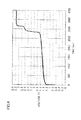
- Fig. 4 shows the relation between the cycle time of charge and discharge and the battery voltage.
- the vanadium redox flow battery system was constructed as comparison systems.
- the basic configuration of each of the comparison systems is the same as that of the above-described example system, and therefore, configured in the similar manner to the above-described example system except that the electrolyte and the operating conditions were different.
- the vanadium electrolyte having a vanadium ion (tetravalent) concentration of 1.7M in the positive electrode and a vanadium ion (trivalent) concentration of 1.7M in the negative electrode was prepared by dissolving vanadium sulfate (tetravalent) in the sulfuric acid aqueous solution (H 2 SO 4 aq) having a sulfuric acid concentration of 2.6M in the positive electrode and dissolving vanadium sulfate (trivalent) in the sulfuric acid aqueous solution (H 2 SO 4 aq) having a sulfuric acid concentration of 1.75M in the negative electrode.
- a small single cell battery including an electrode having an area of 9 cm 2 was manufactured.
- the above-described vanadium electrolyte was used by 10 ml (10 cc) for each of the positive electrode and the negative electrode, to perform charge at a constant current of 540 mA (current density: 60 mA/cm 2 ).
- Fig. 6 shows the relation between the charge time and the battery voltage in the comparison system (I).
- the comparison system (II) is configured in the similar manner to the above-described comparison system (I) except that the amount of the electrolyte and the operating conditions are different.
- the above-described vanadium electrolyte was used by 7 ml (7 cc) for each of the positive electrode and the negative electrode, to perform charge at a constant current of 630 mA (current density: 70 mA/cm 2 ).
- charge was stopped and switched to discharge at the point of time when the voltage reached 1.6V (the state of charge of the vanadium ion: 78%).
- charge and discharge were repeatedly performed in the similar manner.
- Fig. 7 shows the relation between the cycle time of charge and discharge and the battery voltage in the comparison system (II).
- the battery capacity that could be actually utilized is 20.4 minutes with respect to the theoretical capacity of 30.4 minutes (the value converted into discharge time based on the vanadium ion concentration of 1.7M, 7 ml, 630 mA) while the utilization rate of the vanadium ion is 67% ( ⁇ 90%).
- the discharge time (discharge capacity) of the example system was 23.7 minutes, which was 93.7% with respect to the theoretical capacity (25.3 minutes that is the value converted into discharge time based on the vanadium ion concentration of 1.65M, 6 ml, 630 mA), corresponding to the utilization rate exceeding 90%. Furthermore, it was also confirmed that even repetition of charge and discharge did not cause a reduction in the battery capacity and allowed a stable operation.
- 9 ml (9 cc) of an electrolyte having a vanadium ion (trivalent) concentration of 1.7M and a manganese ion (divalent) concentration of 0.5M was prepared by dissolving sulfate salts (vanadium sulfate (trivalent) and manganese sulfate (divalent) in the sulfuric acid aqueous solution (H 2 SO 4 aq) having a sulfuric acid concentration of 1.65M.
- Other configurations were similar to those of the example system in Experimental Example 1.
- 6 ml (6 cc) of an electrolyte having a vanadium ion (tetravalent) concentration of 1.65M, a manganese ion (divalent) concentration of 0.5M and a chromium ion (trivalent) concentration of 0.1M was prepared by dissolving sulfate salts (vanadium sulfate (tetravalent), manganese sulfate (divalent) and chromium sulfate (trivalent)) in the sulfuric acid aqueous solution (H 2 SO 4 aq) having a sulfuric acid concentration of 2.6M.
- 6 ml (6 cc) of an electrolyte having a vanadium ion (trivalent) concentration of 1.65M, a manganese ion (divalent) concentration of 0.5M and a chromium ion (trivalent) concentration of 0.1M was prepared by dissolving sulfate salts (vanadium sulfate (trivalent), manganese sulfate (divalent) and chromium sulfate (trivalent)) in the sulfuric acid aqueous solution (H 2 SO 4 aq) having a sulfuric acid concentration of 1.75M.
- a carbon felt was used for each of the positive and negative electrodes, and an ion exchange membrane was used for the membrane.
- the state of charge exceeding 100% means that, in addition to the fact that the state of charge of the vanadium ion is approximately 100%, Mn 2+ is changed to Mn 3+ (or tetravalent manganese) for charge in the positive electrode while Cr 3+ is changed to Cr 2+ for charge in the negative electrode. This charge was then switched to discharge, which was followed by repetition of charge and discharge on the same charge conditions as those described above.
- the comparison system was configured as a comparison system (I) and a comparison system (II) in Experimental Example 1.
- the example system of the second embodiment even when charge was performed in the state where the state of charge of each electrode exceeded the level equivalent to 100%, a battery voltage rise was suppressed, and thus, at about 2V at most.
- oxygen gas or hydrogen gas was not generated while the electrode did not deteriorate when the cell was disassembled after repetition of charge and discharge.
- the discharge time (discharge capacity) of the example system according to the second embodiment shows a utilization rate exceeding 90% with respect to the theoretical capacity (25.3 minutes that is a value converted into the discharge time based on the vanadium ion concentration of 1.65M, 6 ml, 630 mA).
- even repetition of charge and discharge did not cause a reduction in the battery capacity and allowed a stable operation.
- 9 ml (9 cc) of an electrolyte having a vanadium ion (tetravalent) concentration of 1.7M was prepared by dissolving sulfate salt (vanadium sulfate (tetravalent)) in the sulfuric acid aqueous solution (H 2 SO 4 aq) having a sulfuric acid concentration of 2.6M.
- 6 ml (6 cc) of an electrolyte having a vanadium ion (trivalent) concentration of 1.7M and a chromium ion (trivalent) concentration of 0.1M was prepared by dissolving sulfate salts (vanadium sulfate (trivalent) and chromium sulfate (trivalent)) in the sulfuric acid aqueous solution (H 2 SO 4 aq) having a sulfuric acid concentration of 1.75M.
- the amount of the positive electrode electrolyte is set to be greater than the amount of the negative electrode electrolyte, so that the battery reaction on the negative electrode side (including not only reduction reaction of the vanadium ion but also reduction reaction of the chromium ion) can be sufficiently caused during charge (which is the same in Experimental Example 5 described later).
- a carbon felt was used for each of the positive and negative electrodes, and an ion exchange membrane was used for the membrane.
- Fig. 5 shows the relation between the cycle time of charge and discharge and the battery voltage.
- the comparison system was configured as a comparison system (I) and a comparison system (II) of Experimental Example 1.
- the discharge time (discharge capacity) of the example system according to the third embodiment was 25.9 minutes corresponding to 99.6% with respect to the theoretical capacity (26 minutes which is a value converted into the discharge time based on the vanadium ion concentration of 1.75M, 6 ml, 630 mA).
- the capacity of nearly 100% was achieved and the utilization rate exceeding 90% was also achieved.
- the electrolyte containing a vanadium ion and a chromium ion was used as an electrolyte for each of the positive electrode and the negative electrode.
- sulfate salt chromium sulfate (trivalent)
- a negative electrode electrolyte similar to that in the example system of Experimental Example 4 was prepared (a vanadium ion (trivalent) concentration of 1.7M and a chromium ion (trivalent) concentration of 0.1M, 6 ml (6 cc)).
- Other configurations were the same as those in the example system of Experimental Example 4.
- the present invention is not limited to the above-described embodiments but can be modified as appropriate without deviation from the contents of the present invention.
- the type and the concentration of the metal ion, the concentration of the solvent of the electrolyte, and the like can be changed as appropriate.
- the redox flow battery according to the present invention can be suitably used as a large-capacity storage battery for stabilizing variations in power generation output, storing surplus generated power, and load leveling for power generation of new energy such as solar photovoltaic power generation and wind power generation.
- the redox flow battery according to the present invention can also be suitably used as a large-capacity storage battery attached to a common power plant for voltage sag and power failure prevention and for load leveling.
- 100 redox flow battery 101 membrane, 102 positive electrode cell, 103 negative electrode cell, 104 positive electrode, 105 negative electrode, 106 tank for positive electrode electrolyte, 107 tank for negative electrode electrolyte, 108, 109, 110, 111 pipe, 112, 113 pump.
Landscapes
- Chemical & Material Sciences (AREA)
- Chemical Kinetics & Catalysis (AREA)
- Electrochemistry (AREA)
- General Chemical & Material Sciences (AREA)
- Life Sciences & Earth Sciences (AREA)
- Engineering & Computer Science (AREA)
- Manufacturing & Machinery (AREA)
- Sustainable Development (AREA)
- Sustainable Energy (AREA)
- Fuel Cell (AREA)
- Battery Electrode And Active Subsutance (AREA)
- Secondary Cells (AREA)
Priority Applications (2)
| Application Number | Priority Date | Filing Date | Title |
|---|---|---|---|
| DK13151059.6T DK2581976T3 (da) | 2010-04-27 | 2011-04-27 | Redox-flow-batteri |
| EP13151059.6A EP2581976B1 (de) | 2010-04-27 | 2011-04-27 | Redox-Flussbatterie |
Applications Claiming Priority (4)
| Application Number | Priority Date | Filing Date | Title |
|---|---|---|---|
| JP2010102749A JP2011233373A (ja) | 2010-04-27 | 2010-04-27 | レドックスフロー電池 |
| JP2010102748A JP2011233372A (ja) | 2010-04-27 | 2010-04-27 | レドックスフロー電池 |
| JP2010102747A JP4863172B2 (ja) | 2010-04-27 | 2010-04-27 | レドックスフロー電池 |
| PCT/JP2011/060228 WO2011136256A1 (ja) | 2010-04-27 | 2011-04-27 | レドックスフロー電池 |
Related Child Applications (2)
| Application Number | Title | Priority Date | Filing Date |
|---|---|---|---|
| EP13151059.6A Division EP2581976B1 (de) | 2010-04-27 | 2011-04-27 | Redox-Flussbatterie |
| EP13151059.6 Division-Into | 2013-01-11 |
Publications (3)
| Publication Number | Publication Date |
|---|---|
| EP2485312A1 true EP2485312A1 (de) | 2012-08-08 |
| EP2485312A4 EP2485312A4 (de) | 2013-02-20 |
| EP2485312B1 EP2485312B1 (de) | 2013-09-11 |
Family
ID=44861554
Family Applications (2)
| Application Number | Title | Priority Date | Filing Date |
|---|---|---|---|
| EP11775037.2A Active EP2485312B1 (de) | 2010-04-27 | 2011-04-27 | Redox-flussbatterie |
| EP13151059.6A Active EP2581976B1 (de) | 2010-04-27 | 2011-04-27 | Redox-Flussbatterie |
Family Applications After (1)
| Application Number | Title | Priority Date | Filing Date |
|---|---|---|---|
| EP13151059.6A Active EP2581976B1 (de) | 2010-04-27 | 2011-04-27 | Redox-Flussbatterie |
Country Status (10)
| Country | Link |
|---|---|
| US (2) | US8771857B2 (de) |
| EP (2) | EP2485312B1 (de) |
| KR (2) | KR20120132620A (de) |
| CN (2) | CN102790234A (de) |
| CA (1) | CA2781582C (de) |
| DK (2) | DK2581976T3 (de) |
| ES (2) | ES2458490T3 (de) |
| TW (2) | TW201230482A (de) |
| WO (1) | WO2011136256A1 (de) |
| ZA (1) | ZA201203785B (de) |
Cited By (4)
| Publication number | Priority date | Publication date | Assignee | Title |
|---|---|---|---|---|
| WO2014125331A1 (en) * | 2013-02-14 | 2014-08-21 | Hydraredox Technologies Inc. | ALL-VANADIUM REDOX FLOW BATTERY SYSTEM EMPLOYING A V+4/V+5 REDOX COUPLE AND AN ANCILLARY Ce+3/Ce+4 REDOX COUPLE IN THE POSITIVE ELECTROLYTE SOLUTION |
| WO2017084749A1 (de) * | 2015-11-18 | 2017-05-26 | Friedrich-Schiller-Universität Jena | Hybrid-flow-batterie zur speicherung elektrischer energie und deren verwendung |
| FR3052924A1 (fr) * | 2016-06-21 | 2017-12-22 | Kemwatt | Dispositif de protection contre la surcharge electrique pour accumulateur electrochimique |
| WO2023227226A1 (en) * | 2022-05-27 | 2023-11-30 | Green Energy Storage S.R.L. | Redox flow battery |
Families Citing this family (31)
| Publication number | Priority date | Publication date | Assignee | Title |
|---|---|---|---|---|
| US8785023B2 (en) | 2008-07-07 | 2014-07-22 | Enervault Corparation | Cascade redox flow battery systems |
| US7820321B2 (en) | 2008-07-07 | 2010-10-26 | Enervault Corporation | Redox flow battery system for distributed energy storage |
| US8980484B2 (en) | 2011-03-29 | 2015-03-17 | Enervault Corporation | Monitoring electrolyte concentrations in redox flow battery systems |
| US8916281B2 (en) | 2011-03-29 | 2014-12-23 | Enervault Corporation | Rebalancing electrolytes in redox flow battery systems |
| CN102881932B (zh) * | 2012-09-26 | 2015-04-15 | 清华大学 | 一种含锰的钒液流电池电解液 |
| KR101382031B1 (ko) * | 2012-11-15 | 2014-04-04 | 성균관대학교산학협력단 | 알루미늄―공기 연료 전지용 전해액 및 이를 포함한 알루미늄―공기 연료 전지 |
| CN103022543A (zh) * | 2012-12-20 | 2013-04-03 | 中国科学院长春应用化学研究所 | 一种铈铅液流电池 |
| US8980454B2 (en) | 2013-03-15 | 2015-03-17 | Enervault Corporation | Systems and methods for rebalancing redox flow battery electrolytes |
| CN104143660B (zh) * | 2013-05-09 | 2017-02-08 | 中国科学院大连化学物理研究所 | 一种铅酸‑全钒混合储能电池 |
| JP2016177868A (ja) * | 2013-08-07 | 2016-10-06 | 住友電気工業株式会社 | レドックスフロー電池 |
| CN105474446B (zh) * | 2013-08-07 | 2018-07-03 | 住友电气工业株式会社 | 氧化还原液流电池 |
| AU2014303614B2 (en) * | 2013-08-07 | 2017-09-14 | Sumitomo Electric Industries, Ltd. | Redox flow battery |
| WO2015054878A1 (zh) * | 2013-10-18 | 2015-04-23 | 中国电力科学研究院 | 基于变化率控制储能电站平滑风光发电波动的方法及系统 |
| TWI506292B (zh) * | 2013-10-28 | 2015-11-01 | Inst Nuclear Energy Res Atomic Energy Council | 超音波檢測液流電池充放電狀態裝置 |
| KR101558079B1 (ko) * | 2014-02-20 | 2015-10-06 | 오씨아이 주식회사 | 레독스 흐름 전지 |
| KR101653765B1 (ko) | 2014-05-26 | 2016-09-02 | 롯데케미칼 주식회사 | 레독스 흐름 전지용 양극 전해질 제조 방법 및 레독스 흐름 전지 |
| CN105322186B (zh) * | 2014-07-30 | 2018-06-19 | 中国科学院大连化学物理研究所 | 一种减小全钒液流电池电化学极化的方法 |
| KR20160051476A (ko) | 2014-11-03 | 2016-05-11 | 삼성에스디아이 주식회사 | 이차 전지 및 이를 포함하는 이차 전지 팩 |
| KR20160097491A (ko) | 2015-02-09 | 2016-08-18 | (주)아이디알 | 약제 희석기능을 갖는 휴대용 분무기 |
| US10826100B2 (en) | 2015-04-08 | 2020-11-03 | Lg Chem, Ltd. | Polymer electrolyte membrane, electrochemical cell and flow cell comprising same, method for manufacturing polymer electrolyte membrane, and flow cell electrolyte |
| JP6775300B2 (ja) * | 2016-02-10 | 2020-10-28 | 住友電気工業株式会社 | レドックスフロー電池用電極、及びレドックスフロー電池 |
| EP3509148A4 (de) * | 2016-09-02 | 2020-05-20 | Showa Denko K.K. | Redox-flow-sekundärbatterie und elektrode dafür |
| AU2018246134A1 (en) * | 2017-03-27 | 2019-11-14 | Carlo Alberto BROVERO | Novel leaks containment embodiment for electrochemical stack |
| CN110998948B (zh) * | 2017-08-10 | 2022-10-25 | 京瓷株式会社 | 液流电池 |
| KR20190058136A (ko) * | 2017-11-21 | 2019-05-29 | 롯데케미칼 주식회사 | 레독스 흐름전지용 전해액 및 이를 포함하는 레독스 흐름전지 |
| CN108258292A (zh) * | 2018-03-29 | 2018-07-06 | 四川大学 | 一种全钒液流电池正极电解液及其配置方法 |
| CN109659588A (zh) * | 2018-12-10 | 2019-04-19 | 合肥沃工电气自动化有限公司 | 一种钒电池自启动运行控制方法 |
| NL2022980B1 (nl) | 2019-04-18 | 2020-10-26 | Lamaxan Holding B V | Een energie-opslag-ponton, een schip, een scheepvaartsysteem en een werkwijze voor het bedrijven van het scheepvaartsystem. |
| CN110911704A (zh) * | 2019-11-26 | 2020-03-24 | 中国科学院金属研究所 | 一种铁铬液流电池电解液及其应用 |
| CN110912198B (zh) * | 2019-12-17 | 2021-10-01 | 陈翔 | 一种应用于智能家居的自动化控制系统及控制方法 |
| CN115642278A (zh) * | 2022-09-15 | 2023-01-24 | 大连融科储能集团股份有限公司 | 一种钒铬电解液、其制备方法及由其构成的液流电池 |
Citations (4)
| Publication number | Priority date | Publication date | Assignee | Title |
|---|---|---|---|---|
| EP0517217A1 (de) * | 1991-06-06 | 1992-12-09 | Director-General Of The Agency Of Industrial Science And Technology | Redox-Batterie |
| US5250158A (en) * | 1990-10-15 | 1993-10-05 | Director-General, Agency Of Industrial Science And Technology | Method for producing vanadium electrolytic solution |
| WO2008009992A2 (en) * | 2006-07-19 | 2008-01-24 | Acal Energy Limited | Fuel cells |
| WO2010094657A1 (de) * | 2009-02-18 | 2010-08-26 | Fraunhofer-Gesellschaft zur Förderung der angewandten Forschung e.V. | Methode zur speicherung von elektrischer energie in ionischen flüssigkeiten |
Family Cites Families (20)
| Publication number | Priority date | Publication date | Assignee | Title |
|---|---|---|---|---|
| JPS5913154B2 (ja) * | 1980-06-17 | 1984-03-28 | 工業技術院長 | レドツクス電池 |
| US4362791A (en) | 1980-06-17 | 1982-12-07 | Agency Of Industrial Science & Technology | Redox battery |
| JPS611270U (ja) * | 1984-06-11 | 1986-01-07 | 住友電気工業株式会社 | 電池 |
| JPS6122574A (ja) | 1984-07-09 | 1986-01-31 | Sumitomo Electric Ind Ltd | 電池 |
| JPS62216176A (ja) | 1986-03-15 | 1987-09-22 | Agency Of Ind Science & Technol | レドツクス電池用電解液 |
| JP2802326B2 (ja) * | 1988-09-14 | 1998-09-24 | 工業技術院長 | 教材用レドックス電地 |
| JPH0758625B2 (ja) * | 1990-05-11 | 1995-06-21 | 工業技術院長 | レドックス電池 |
| DE69432428D1 (de) * | 1993-11-17 | 2003-05-08 | Pinnacle Vrb Ltd | Stabilisierte elektrolytlösungen, verfahren und deren herstellung und redoxzellen und batterien, die diese lösungen enthalten |
| JP3143568B2 (ja) | 1994-11-08 | 2001-03-07 | 住友電気工業株式会社 | レドックスフロー電池の運転方法 |
| US6468688B2 (en) | 1995-05-03 | 2002-10-22 | Pinnacle Vrb Limited | High energy density vanadium electrolyte solutions, methods of preparation thereof and all-vanadium redox cells and batteries containing high energy vanadium electrolyte solutions |
| US6085015A (en) * | 1997-03-25 | 2000-07-04 | Hydro-Quebec | Lithium insertion electrode materials based on orthosilicate derivatives |
| JP3231273B2 (ja) | 1998-01-08 | 2001-11-19 | 住友電気工業株式会社 | 電解液流通型電池 |
| JP2002175831A (ja) | 2000-09-29 | 2002-06-21 | Shinko Kagaku Kogyo Kk | バナジウムレドックスフロー電池用電解液の製造方法 |
| US7560189B2 (en) | 2001-08-10 | 2009-07-14 | Plurion Limited | Mixed electrolyte battery |
| JP2003157884A (ja) | 2001-11-21 | 2003-05-30 | Sumitomo Electric Ind Ltd | バナジウムレドックスフロー電池の充電方法 |
| AUPS192102A0 (en) | 2002-04-23 | 2002-05-30 | Unisearch Limited | Vanadium bromide redox flow battery |
| JP2006147374A (ja) | 2004-11-19 | 2006-06-08 | Kansai Electric Power Co Inc:The | バナジウムレドックスフロー電池システムの運転方法 |
| JP4804126B2 (ja) | 2005-11-25 | 2011-11-02 | 三菱電機株式会社 | 圧力センサ |
| CN101593841B (zh) | 2008-05-30 | 2012-05-30 | 比亚迪股份有限公司 | 一种氧化还原液流电池和氧化还原液流电池组 |
| CN101635363B (zh) | 2008-07-27 | 2012-05-30 | 比亚迪股份有限公司 | 一种全钒离子液流电池电解液及其制备方法及电池 |
-
2011
- 2011-04-27 CA CA2781582A patent/CA2781582C/en active Active
- 2011-04-27 DK DK13151059.6T patent/DK2581976T3/da active
- 2011-04-27 DK DK11775037.2T patent/DK2485312T3/da active
- 2011-04-27 TW TW100114630A patent/TW201230482A/zh unknown
- 2011-04-27 ES ES13151059.6T patent/ES2458490T3/es active Active
- 2011-04-27 US US13/505,281 patent/US8771857B2/en active Active
- 2011-04-27 CN CN2012102543060A patent/CN102790234A/zh active Pending
- 2011-04-27 CN CN2011800045859A patent/CN102652377B/zh active Active
- 2011-04-27 WO PCT/JP2011/060228 patent/WO2011136256A1/ja active Application Filing
- 2011-04-27 KR KR1020127012392A patent/KR20120132620A/ko not_active Application Discontinuation
- 2011-04-27 TW TW101118964A patent/TW201246682A/zh unknown
- 2011-04-27 EP EP11775037.2A patent/EP2485312B1/de active Active
- 2011-04-27 ES ES11775037T patent/ES2429359T3/es active Active
- 2011-04-27 KR KR1020127012072A patent/KR101178327B1/ko active IP Right Grant
- 2011-04-27 EP EP13151059.6A patent/EP2581976B1/de active Active
-
2012
- 2012-05-16 US US13/472,943 patent/US20120282509A1/en not_active Abandoned
- 2012-05-23 ZA ZA2012/03785A patent/ZA201203785B/en unknown
Patent Citations (4)
| Publication number | Priority date | Publication date | Assignee | Title |
|---|---|---|---|---|
| US5250158A (en) * | 1990-10-15 | 1993-10-05 | Director-General, Agency Of Industrial Science And Technology | Method for producing vanadium electrolytic solution |
| EP0517217A1 (de) * | 1991-06-06 | 1992-12-09 | Director-General Of The Agency Of Industrial Science And Technology | Redox-Batterie |
| WO2008009992A2 (en) * | 2006-07-19 | 2008-01-24 | Acal Energy Limited | Fuel cells |
| WO2010094657A1 (de) * | 2009-02-18 | 2010-08-26 | Fraunhofer-Gesellschaft zur Förderung der angewandten Forschung e.V. | Methode zur speicherung von elektrischer energie in ionischen flüssigkeiten |
Non-Patent Citations (1)
| Title |
|---|
| See also references of WO2011136256A1 * |
Cited By (8)
| Publication number | Priority date | Publication date | Assignee | Title |
|---|---|---|---|---|
| WO2014125331A1 (en) * | 2013-02-14 | 2014-08-21 | Hydraredox Technologies Inc. | ALL-VANADIUM REDOX FLOW BATTERY SYSTEM EMPLOYING A V+4/V+5 REDOX COUPLE AND AN ANCILLARY Ce+3/Ce+4 REDOX COUPLE IN THE POSITIVE ELECTROLYTE SOLUTION |
| US10115993B2 (en) | 2013-02-14 | 2018-10-30 | Hydraredox Technologies Holdings Ltd. | All-vanadium redox flow battery system employing a V+4/V+5 redox couple and an ancillary Ce+3/Ce+4 redox couple in the positive electrolyte solution |
| WO2017084749A1 (de) * | 2015-11-18 | 2017-05-26 | Friedrich-Schiller-Universität Jena | Hybrid-flow-batterie zur speicherung elektrischer energie und deren verwendung |
| AU2016356485B2 (en) * | 2015-11-18 | 2021-12-23 | Jenabatteries GmbH | Hybrid flow battery for storing electrical energy and use thereof |
| US11283077B2 (en) * | 2015-11-18 | 2022-03-22 | Jena Batteries, Gmbh | Hybrid flow battery for storing electrical energy and use thereof |
| FR3052924A1 (fr) * | 2016-06-21 | 2017-12-22 | Kemwatt | Dispositif de protection contre la surcharge electrique pour accumulateur electrochimique |
| WO2017220593A1 (fr) * | 2016-06-21 | 2017-12-28 | Kemwatt | Dispositif de protection contre la surcharge électrique pour accumulateur électrochimique |
| WO2023227226A1 (en) * | 2022-05-27 | 2023-11-30 | Green Energy Storage S.R.L. | Redox flow battery |
Also Published As
| Publication number | Publication date |
|---|---|
| ZA201203785B (en) | 2013-01-30 |
| ES2429359T3 (es) | 2013-11-14 |
| CN102652377B (zh) | 2013-07-17 |
| WO2011136256A1 (ja) | 2011-11-03 |
| EP2581976A1 (de) | 2013-04-17 |
| TW201246682A (en) | 2012-11-16 |
| KR101178327B1 (ko) | 2012-08-29 |
| EP2581976B1 (de) | 2014-03-19 |
| KR20120132620A (ko) | 2012-12-06 |
| KR20120056894A (ko) | 2012-06-04 |
| DK2485312T3 (da) | 2013-10-14 |
| EP2485312B1 (de) | 2013-09-11 |
| EP2485312A4 (de) | 2013-02-20 |
| AU2011246147A1 (en) | 2012-06-07 |
| US20120244405A1 (en) | 2012-09-27 |
| CN102652377A (zh) | 2012-08-29 |
| TW201230482A (en) | 2012-07-16 |
| AU2011246147B2 (en) | 2014-09-25 |
| TWI378596B (de) | 2012-12-01 |
| CN102790234A (zh) | 2012-11-21 |
| US20120282509A1 (en) | 2012-11-08 |
| US8771857B2 (en) | 2014-07-08 |
| CA2781582C (en) | 2013-05-28 |
| CA2781582A1 (en) | 2011-11-03 |
| ES2458490T3 (es) | 2014-05-05 |
| DK2581976T3 (da) | 2014-05-12 |
Similar Documents
| Publication | Publication Date | Title |
|---|---|---|
| EP2485312B1 (de) | Redox-flussbatterie | |
| US8288030B2 (en) | Redox flow battery | |
| WO2011111717A1 (ja) | レドックスフロー電池 | |
| JP2011233372A (ja) | レドックスフロー電池 | |
| JP2012079679A (ja) | レドックスフロー電池 | |
| JP2013008642A (ja) | レドックスフロー電池 | |
| JP2011210696A (ja) | レドックスフロー電池 | |
| JP4863172B2 (ja) | レドックスフロー電池 | |
| JP5489008B2 (ja) | レドックスフロー電池 | |
| JP2011233373A (ja) | レドックスフロー電池 |
Legal Events
| Date | Code | Title | Description |
|---|---|---|---|
| PUAI | Public reference made under article 153(3) epc to a published international application that has entered the european phase |
Free format text: ORIGINAL CODE: 0009012 |
|
| 17P | Request for examination filed |
Effective date: 20120501 |
|
| AK | Designated contracting states |
Kind code of ref document: A1 Designated state(s): AL AT BE BG CH CY CZ DE DK EE ES FI FR GB GR HR HU IE IS IT LI LT LU LV MC MK MT NL NO PL PT RO RS SE SI SK SM TR |
|
| REG | Reference to a national code |
Ref country code: HK Ref legal event code: DE Ref document number: 1167932 Country of ref document: HK |
|
| A4 | Supplementary search report drawn up and despatched |
Effective date: 20130121 |
|
| RIC1 | Information provided on ipc code assigned before grant |
Ipc: H01M 8/18 20060101AFI20130115BHEP |
|
| GRAP | Despatch of communication of intention to grant a patent |
Free format text: ORIGINAL CODE: EPIDOSNIGR1 |
|
| DAX | Request for extension of the european patent (deleted) | ||
| INTG | Intention to grant announced |
Effective date: 20130327 |
|
| GRAS | Grant fee paid |
Free format text: ORIGINAL CODE: EPIDOSNIGR3 |
|
| GRAA | (expected) grant |
Free format text: ORIGINAL CODE: 0009210 |
|
| AK | Designated contracting states |
Kind code of ref document: B1 Designated state(s): AL AT BE BG CH CY CZ DE DK EE ES FI FR GB GR HR HU IE IS IT LI LT LU LV MC MK MT NL NO PL PT RO RS SE SI SK SM TR |
|
| REG | Reference to a national code |
Ref country code: GB Ref legal event code: FG4D |
|
| REG | Reference to a national code |
Ref country code: CH Ref legal event code: EP |
|
| REG | Reference to a national code |
Ref country code: AT Ref legal event code: REF Ref document number: 632070 Country of ref document: AT Kind code of ref document: T Effective date: 20130915 |
|
| REG | Reference to a national code |
Ref country code: IE Ref legal event code: FG4D |
|
| REG | Reference to a national code |
Ref country code: DK Ref legal event code: T3 Effective date: 20131010 Ref country code: DK Ref legal event code: T3 |
|
| REG | Reference to a national code |
Ref country code: NL Ref legal event code: T3 |
|
| REG | Reference to a national code |
Ref country code: DE Ref legal event code: R096 Ref document number: 602011003046 Country of ref document: DE Effective date: 20131107 |
|
| REG | Reference to a national code |
Ref country code: ES Ref legal event code: FG2A Ref document number: 2429359 Country of ref document: ES Kind code of ref document: T3 Effective date: 20131114 |
|
| PG25 | Lapsed in a contracting state [announced via postgrant information from national office to epo] |
Ref country code: HR Free format text: LAPSE BECAUSE OF FAILURE TO SUBMIT A TRANSLATION OF THE DESCRIPTION OR TO PAY THE FEE WITHIN THE PRESCRIBED TIME-LIMIT Effective date: 20130911 Ref country code: NO Free format text: LAPSE BECAUSE OF FAILURE TO SUBMIT A TRANSLATION OF THE DESCRIPTION OR TO PAY THE FEE WITHIN THE PRESCRIBED TIME-LIMIT Effective date: 20131211 Ref country code: CY Free format text: LAPSE BECAUSE OF FAILURE TO SUBMIT A TRANSLATION OF THE DESCRIPTION OR TO PAY THE FEE WITHIN THE PRESCRIBED TIME-LIMIT Effective date: 20130904 Ref country code: LT Free format text: LAPSE BECAUSE OF FAILURE TO SUBMIT A TRANSLATION OF THE DESCRIPTION OR TO PAY THE FEE WITHIN THE PRESCRIBED TIME-LIMIT Effective date: 20130911 Ref country code: SE Free format text: LAPSE BECAUSE OF FAILURE TO SUBMIT A TRANSLATION OF THE DESCRIPTION OR TO PAY THE FEE WITHIN THE PRESCRIBED TIME-LIMIT Effective date: 20130911 |
|
| REG | Reference to a national code |
Ref country code: LT Ref legal event code: MG4D |
|
| PG25 | Lapsed in a contracting state [announced via postgrant information from national office to epo] |
Ref country code: SI Free format text: LAPSE BECAUSE OF FAILURE TO SUBMIT A TRANSLATION OF THE DESCRIPTION OR TO PAY THE FEE WITHIN THE PRESCRIBED TIME-LIMIT Effective date: 20130911 Ref country code: GR Free format text: LAPSE BECAUSE OF FAILURE TO SUBMIT A TRANSLATION OF THE DESCRIPTION OR TO PAY THE FEE WITHIN THE PRESCRIBED TIME-LIMIT Effective date: 20131212 Ref country code: FI Free format text: LAPSE BECAUSE OF FAILURE TO SUBMIT A TRANSLATION OF THE DESCRIPTION OR TO PAY THE FEE WITHIN THE PRESCRIBED TIME-LIMIT Effective date: 20130911 Ref country code: LV Free format text: LAPSE BECAUSE OF FAILURE TO SUBMIT A TRANSLATION OF THE DESCRIPTION OR TO PAY THE FEE WITHIN THE PRESCRIBED TIME-LIMIT Effective date: 20130911 |
|
| PG25 | Lapsed in a contracting state [announced via postgrant information from national office to epo] |
Ref country code: BE Free format text: LAPSE BECAUSE OF FAILURE TO SUBMIT A TRANSLATION OF THE DESCRIPTION OR TO PAY THE FEE WITHIN THE PRESCRIBED TIME-LIMIT Effective date: 20130911 Ref country code: CY Free format text: LAPSE BECAUSE OF FAILURE TO SUBMIT A TRANSLATION OF THE DESCRIPTION OR TO PAY THE FEE WITHIN THE PRESCRIBED TIME-LIMIT Effective date: 20130911 |
|
| PG25 | Lapsed in a contracting state [announced via postgrant information from national office to epo] |
Ref country code: RO Free format text: LAPSE BECAUSE OF FAILURE TO SUBMIT A TRANSLATION OF THE DESCRIPTION OR TO PAY THE FEE WITHIN THE PRESCRIBED TIME-LIMIT Effective date: 20130911 Ref country code: SK Free format text: LAPSE BECAUSE OF FAILURE TO SUBMIT A TRANSLATION OF THE DESCRIPTION OR TO PAY THE FEE WITHIN THE PRESCRIBED TIME-LIMIT Effective date: 20130911 Ref country code: IS Free format text: LAPSE BECAUSE OF FAILURE TO SUBMIT A TRANSLATION OF THE DESCRIPTION OR TO PAY THE FEE WITHIN THE PRESCRIBED TIME-LIMIT Effective date: 20140111 Ref country code: CZ Free format text: LAPSE BECAUSE OF FAILURE TO SUBMIT A TRANSLATION OF THE DESCRIPTION OR TO PAY THE FEE WITHIN THE PRESCRIBED TIME-LIMIT Effective date: 20130911 Ref country code: EE Free format text: LAPSE BECAUSE OF FAILURE TO SUBMIT A TRANSLATION OF THE DESCRIPTION OR TO PAY THE FEE WITHIN THE PRESCRIBED TIME-LIMIT Effective date: 20130911 |
|
| PG25 | Lapsed in a contracting state [announced via postgrant information from national office to epo] |
Ref country code: PL Free format text: LAPSE BECAUSE OF FAILURE TO SUBMIT A TRANSLATION OF THE DESCRIPTION OR TO PAY THE FEE WITHIN THE PRESCRIBED TIME-LIMIT Effective date: 20130911 |
|
| REG | Reference to a national code |
Ref country code: DE Ref legal event code: R097 Ref document number: 602011003046 Country of ref document: DE |
|
| PG25 | Lapsed in a contracting state [announced via postgrant information from national office to epo] |
Ref country code: PT Free format text: LAPSE BECAUSE OF FAILURE TO SUBMIT A TRANSLATION OF THE DESCRIPTION OR TO PAY THE FEE WITHIN THE PRESCRIBED TIME-LIMIT Effective date: 20140113 |
|
| PLBE | No opposition filed within time limit |
Free format text: ORIGINAL CODE: 0009261 |
|
| STAA | Information on the status of an ep patent application or granted ep patent |
Free format text: STATUS: NO OPPOSITION FILED WITHIN TIME LIMIT |
|
| 26N | No opposition filed |
Effective date: 20140612 |
|
| REG | Reference to a national code |
Ref country code: DE Ref legal event code: R097 Ref document number: 602011003046 Country of ref document: DE Effective date: 20140612 |
|
| PG25 | Lapsed in a contracting state [announced via postgrant information from national office to epo] |
Ref country code: MC Free format text: LAPSE BECAUSE OF FAILURE TO SUBMIT A TRANSLATION OF THE DESCRIPTION OR TO PAY THE FEE WITHIN THE PRESCRIBED TIME-LIMIT Effective date: 20130911 Ref country code: LU Free format text: LAPSE BECAUSE OF FAILURE TO SUBMIT A TRANSLATION OF THE DESCRIPTION OR TO PAY THE FEE WITHIN THE PRESCRIBED TIME-LIMIT Effective date: 20140427 |
|
| REG | Reference to a national code |
Ref country code: CH Ref legal event code: PL |
|
| REG | Reference to a national code |
Ref country code: IE Ref legal event code: MM4A |
|
| PG25 | Lapsed in a contracting state [announced via postgrant information from national office to epo] |
Ref country code: CH Free format text: LAPSE BECAUSE OF NON-PAYMENT OF DUE FEES Effective date: 20140430 Ref country code: LI Free format text: LAPSE BECAUSE OF NON-PAYMENT OF DUE FEES Effective date: 20140430 |
|
| PG25 | Lapsed in a contracting state [announced via postgrant information from national office to epo] |
Ref country code: IE Free format text: LAPSE BECAUSE OF NON-PAYMENT OF DUE FEES Effective date: 20140427 |
|
| REG | Reference to a national code |
Ref country code: FR Ref legal event code: PLFP Year of fee payment: 6 |
|
| PG25 | Lapsed in a contracting state [announced via postgrant information from national office to epo] |
Ref country code: MT Free format text: LAPSE BECAUSE OF FAILURE TO SUBMIT A TRANSLATION OF THE DESCRIPTION OR TO PAY THE FEE WITHIN THE PRESCRIBED TIME-LIMIT Effective date: 20130911 |
|
| PG25 | Lapsed in a contracting state [announced via postgrant information from national office to epo] |
Ref country code: SM Free format text: LAPSE BECAUSE OF FAILURE TO SUBMIT A TRANSLATION OF THE DESCRIPTION OR TO PAY THE FEE WITHIN THE PRESCRIBED TIME-LIMIT Effective date: 20130911 |
|
| PG25 | Lapsed in a contracting state [announced via postgrant information from national office to epo] |
Ref country code: RS Free format text: LAPSE BECAUSE OF NON-PAYMENT OF DUE FEES Effective date: 20130911 Ref country code: BG Free format text: LAPSE BECAUSE OF FAILURE TO SUBMIT A TRANSLATION OF THE DESCRIPTION OR TO PAY THE FEE WITHIN THE PRESCRIBED TIME-LIMIT Effective date: 20130911 |
|
| PG25 | Lapsed in a contracting state [announced via postgrant information from national office to epo] |
Ref country code: TR Free format text: LAPSE BECAUSE OF FAILURE TO SUBMIT A TRANSLATION OF THE DESCRIPTION OR TO PAY THE FEE WITHIN THE PRESCRIBED TIME-LIMIT Effective date: 20130911 Ref country code: HU Free format text: LAPSE BECAUSE OF FAILURE TO SUBMIT A TRANSLATION OF THE DESCRIPTION OR TO PAY THE FEE WITHIN THE PRESCRIBED TIME-LIMIT; INVALID AB INITIO Effective date: 20110427 |
|
| REG | Reference to a national code |
Ref country code: FR Ref legal event code: PLFP Year of fee payment: 7 |
|
| REG | Reference to a national code |
Ref country code: FR Ref legal event code: PLFP Year of fee payment: 8 |
|
| PG25 | Lapsed in a contracting state [announced via postgrant information from national office to epo] |
Ref country code: MK Free format text: LAPSE BECAUSE OF FAILURE TO SUBMIT A TRANSLATION OF THE DESCRIPTION OR TO PAY THE FEE WITHIN THE PRESCRIBED TIME-LIMIT Effective date: 20130911 |
|
| PG25 | Lapsed in a contracting state [announced via postgrant information from national office to epo] |
Ref country code: AL Free format text: LAPSE BECAUSE OF FAILURE TO SUBMIT A TRANSLATION OF THE DESCRIPTION OR TO PAY THE FEE WITHIN THE PRESCRIBED TIME-LIMIT Effective date: 20130911 |
|
| REG | Reference to a national code |
Ref country code: HK Ref legal event code: WD Ref document number: 1167932 Country of ref document: HK |
|
| P01 | Opt-out of the competence of the unified patent court (upc) registered |
Effective date: 20230515 |
|
| PGFP | Annual fee paid to national office [announced via postgrant information from national office to epo] |
Ref country code: NL Payment date: 20240315 Year of fee payment: 14 |
|
| PGFP | Annual fee paid to national office [announced via postgrant information from national office to epo] |
Ref country code: GB Payment date: 20240307 Year of fee payment: 14 |
|
| PGFP | Annual fee paid to national office [announced via postgrant information from national office to epo] |
Ref country code: IT Payment date: 20240313 Year of fee payment: 14 Ref country code: FR Payment date: 20240308 Year of fee payment: 14 |
|
| PGFP | Annual fee paid to national office [announced via postgrant information from national office to epo] |
Ref country code: DE Payment date: 20240306 Year of fee payment: 14 |
|
| PGFP | Annual fee paid to national office [announced via postgrant information from national office to epo] |
Ref country code: DK Payment date: 20240411 Year of fee payment: 14 |
|
| PGFP | Annual fee paid to national office [announced via postgrant information from national office to epo] |
Ref country code: ES Payment date: 20240507 Year of fee payment: 14 |
|
| PGFP | Annual fee paid to national office [announced via postgrant information from national office to epo] |
Ref country code: AT Payment date: 20240326 Year of fee payment: 14 |