EP2482092B1 - Sonnennachführungsverfahren - Google Patents
Sonnennachführungsverfahren Download PDFInfo
- Publication number
- EP2482092B1 EP2482092B1 EP12151390.7A EP12151390A EP2482092B1 EP 2482092 B1 EP2482092 B1 EP 2482092B1 EP 12151390 A EP12151390 A EP 12151390A EP 2482092 B1 EP2482092 B1 EP 2482092B1
- Authority
- EP
- European Patent Office
- Prior art keywords
- photovoltaic cell
- short
- cell device
- circuit current
- attitude
- Prior art date
- Legal status (The legal status is an assumption and is not a legal conclusion. Google has not performed a legal analysis and makes no representation as to the accuracy of the status listed.)
- Active
Links
Images


Classifications
-
- G—PHYSICS
- G01—MEASURING; TESTING
- G01S—RADIO DIRECTION-FINDING; RADIO NAVIGATION; DETERMINING DISTANCE OR VELOCITY BY USE OF RADIO WAVES; LOCATING OR PRESENCE-DETECTING BY USE OF THE REFLECTION OR RERADIATION OF RADIO WAVES; ANALOGOUS ARRANGEMENTS USING OTHER WAVES
- G01S3/00—Direction-finders for determining the direction from which infrasonic, sonic, ultrasonic or electromagnetic waves, or particle emission, not having a directional significance, are being received
- G01S3/78—Direction-finders for determining the direction from which infrasonic, sonic, ultrasonic or electromagnetic waves, or particle emission, not having a directional significance, are being received using electromagnetic waves other than radio waves
- G01S3/782—Systems for determining direction or deviation from predetermined direction
- G01S3/785—Systems for determining direction or deviation from predetermined direction using adjustment of orientation of directivity characteristics of a detector or detector system to give a desired condition of signal derived from that detector or detector system
- G01S3/786—Systems for determining direction or deviation from predetermined direction using adjustment of orientation of directivity characteristics of a detector or detector system to give a desired condition of signal derived from that detector or detector system the desired condition being maintained automatically
- G01S3/7861—Solar tracking systems
-
- F—MECHANICAL ENGINEERING; LIGHTING; HEATING; WEAPONS; BLASTING
- F24—HEATING; RANGES; VENTILATING
- F24S—SOLAR HEAT COLLECTORS; SOLAR HEAT SYSTEMS
- F24S30/00—Arrangements for moving or orienting solar heat collector modules
- F24S30/40—Arrangements for moving or orienting solar heat collector modules for rotary movement
- F24S30/45—Arrangements for moving or orienting solar heat collector modules for rotary movement with two rotation axes
- F24S30/452—Vertical primary axis
-
- F—MECHANICAL ENGINEERING; LIGHTING; HEATING; WEAPONS; BLASTING
- F24—HEATING; RANGES; VENTILATING
- F24S—SOLAR HEAT COLLECTORS; SOLAR HEAT SYSTEMS
- F24S50/00—Arrangements for controlling solar heat collectors
- F24S50/20—Arrangements for controlling solar heat collectors for tracking
-
- G—PHYSICS
- G05—CONTROLLING; REGULATING
- G05D—SYSTEMS FOR CONTROLLING OR REGULATING NON-ELECTRIC VARIABLES
- G05D3/00—Control of position or direction
- G05D3/10—Control of position or direction without using feedback
- G05D3/105—Solar tracker
-
- H—ELECTRICITY
- H02—GENERATION; CONVERSION OR DISTRIBUTION OF ELECTRIC POWER
- H02S—GENERATION OF ELECTRIC POWER BY CONVERSION OF INFRARED RADIATION, VISIBLE LIGHT OR ULTRAVIOLET LIGHT, e.g. USING PHOTOVOLTAIC [PV] MODULES
- H02S20/00—Supporting structures for PV modules
-
- H—ELECTRICITY
- H02—GENERATION; CONVERSION OR DISTRIBUTION OF ELECTRIC POWER
- H02S—GENERATION OF ELECTRIC POWER BY CONVERSION OF INFRARED RADIATION, VISIBLE LIGHT OR ULTRAVIOLET LIGHT, e.g. USING PHOTOVOLTAIC [PV] MODULES
- H02S20/00—Supporting structures for PV modules
- H02S20/30—Supporting structures being movable or adjustable, e.g. for angle adjustment
- H02S20/32—Supporting structures being movable or adjustable, e.g. for angle adjustment specially adapted for solar tracking
-
- Y—GENERAL TAGGING OF NEW TECHNOLOGICAL DEVELOPMENTS; GENERAL TAGGING OF CROSS-SECTIONAL TECHNOLOGIES SPANNING OVER SEVERAL SECTIONS OF THE IPC; TECHNICAL SUBJECTS COVERED BY FORMER USPC CROSS-REFERENCE ART COLLECTIONS [XRACs] AND DIGESTS
- Y02—TECHNOLOGIES OR APPLICATIONS FOR MITIGATION OR ADAPTATION AGAINST CLIMATE CHANGE
- Y02E—REDUCTION OF GREENHOUSE GAS [GHG] EMISSIONS, RELATED TO ENERGY GENERATION, TRANSMISSION OR DISTRIBUTION
- Y02E10/00—Energy generation through renewable energy sources
- Y02E10/40—Solar thermal energy, e.g. solar towers
- Y02E10/47—Mountings or tracking
-
- Y—GENERAL TAGGING OF NEW TECHNOLOGICAL DEVELOPMENTS; GENERAL TAGGING OF CROSS-SECTIONAL TECHNOLOGIES SPANNING OVER SEVERAL SECTIONS OF THE IPC; TECHNICAL SUBJECTS COVERED BY FORMER USPC CROSS-REFERENCE ART COLLECTIONS [XRACs] AND DIGESTS
- Y02—TECHNOLOGIES OR APPLICATIONS FOR MITIGATION OR ADAPTATION AGAINST CLIMATE CHANGE
- Y02E—REDUCTION OF GREENHOUSE GAS [GHG] EMISSIONS, RELATED TO ENERGY GENERATION, TRANSMISSION OR DISTRIBUTION
- Y02E10/00—Energy generation through renewable energy sources
- Y02E10/50—Photovoltaic [PV] energy
Definitions
- the present disclosure relates to a sun tracking method and a sun tracking system. More particularly, the present disclosure relates to a sun tracking method and a sun tracking system that is able to continuously track the position of the sun without additional light sensors, calculation of the solar orbit function, regular calibration of the mechanical structure of the sun tracking system regularly or precise initial installation of the sun tracking system.
- Concentrated photovoltaic (CPV) system is a conventional photovoltaic device that uses optical devices to concentrate a large area of sunlight onto the photovoltaic cells.
- the method of concentrating the sunlight reduces the area of the photovoltaic cells and makes the CPV system cost-effective.
- it makes the CPV system become sensitive to the incident angle of the sunlight as well.
- the further reduction of the area of the photovoltaic cells adapted in the highly concentrated photovoltaic system makes the offset of the tracking angle that is tolerable by the light-concentrating module reduced at the same time. Accordingly, the precision of the tracking system becomes more and more important.
- a tracking device is necessary to be adapted to the light-concentrating module to modulate the axis of the light-concentrating module toward the sun.
- the tracking device performs the tracking mechanism in cooperation with the sensing device.
- the sensing device makes use of a plurality of light sensors disposed in different places and the pillars that generate shadows to make the light incident to the light sensors uneven.
- the uneven incident light results in different voltage outputs generated by the light sensors.
- the direction of the incident light that has the highest intensity can hence be determined by the voltage values of the voltage outputs.
- sensors such as optical conductors, photodiodes, phototransistors and photovoltaic cells.
- Each of the light sensors generates a corresponding short-circuit current according to the intensity of the incident sunlight, where the short-circuit current becomes larger when the intensity of the sunlight becomes higher. The amount of the short-circuit current is then outputted in a voltage form.
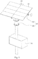
- Fig. 1 is a 3-D view of a conventional sun tracking system.
- the conventional sun tracking system is a CPV system having a photovoltaic cell device 11, an attitude control device 12, a light-sensing device 13 and a micro-control device 14.
- the micro-control device 14 is coupled to the attitude control device 12 and the light-sensing device 13.
- the attitude control device 12 has an azimuth angle control unit 121 and an elevation angle control unit 122 to adjust the attitude (including an azimuth angle and an elevation angle) of the photovoltaic cell device 11.
- the light-sensing device 13 keeps sensing the intensity of the light incident thereon.
- the micro-control device 14 drives a motor driving device to drive a motor in the attitude control device 12 according to the light-sensing result to adjust the attitude of the photovoltaic cell device 11 and the light-sensing device 13.
- a time-consuming initial calibration is needed when the light-sensing device is adapted to make the four (or a plurality of) light sensors of the light-sensing device generate the same amount of output voltage/current when the photovoltaic cell device 11 faces directly to the sun.
- the mechanical structure of the system may be damaged, deformed or loosened due to the environmental effect to change the relative position of the photovoltaic cell device 11 and the light-sensing device 13.
- the light sensors of the light-sensing device 13 deteriorate over time since they are under the sun for a long time. Accordingly, the direction of the incident light having the highest intensity detected by the light-sensing device 13 may not correspond to the attitude of the photovoltaic cell device 11 that can receive the largest amount of sunlight. Comparing to the initial state of the sun tracking system, the efficiency of the conventional sun tracking system degrades more when the operation time is longer.
- some conventional sun tracking systems use complex solar orbit function to calculate the position of the sun to adjust the attitude of the photovoltaic cell device.
- the result of the calculation of the complex solar orbit function is reliable only when the initial position of the sun is extremely precise. If an offset of the initial position is present, the error is generated in the calculation result. Therefore, a precise initial setting of the architecture and the position of the system is unavoidable in such a kind of conventional sun tracking systems. The installation cost of the conventional sun tracking systems thus increases.
- a sun tracking method and a sun tracking system that is able to continuously track the position of the sun without additional light sensors, calculation of the solar orbit function, regular calibration of the mechanical structure of the sun tracking system regularly or precise initial installation of the sun tracking system.
- a maximum power point tracking (MPPT) device is installed.
- the maximum power point tracking (MPPT) device has a voltage-increasing circuit or a voltage-increasing/decreasing circuit.
- a measurement of the voltage, current or power is performed to generate a feedback signal to control the power transistors of the voltage-increasing circuit or the voltage-increasing/decreasing circuit such that the photovoltaic cell device can always generate the maximum output power after the photovoltaic conversion no matter what the condition of the illumination of the sunlight and the load is.
- the short-circuit current of the photovoltaic cell or the output power of the photovoltaic cell is also at the maximum value when the photovoltaic cell device faces directly to the sun.
- US 2007/236187 A1 discloses a high-performance solar photovoltaic (PV) energy conversion system.
- the power circuit is made of a two-stage circuit, connecting a step-up DC-DC converter and a full-bridge inverter in serial, wherein an adaptive perturbation and observation method to increase tracking speed of maximum power position and at the same time reduces energy loss.
- the full-bridge inverter's output has to have the same phase with the utility power in order to achieve unit power factor and increase the system efficiency.
- WO 2009/072075 A2 discloses a photovoltaic system including a photovoltaic cell, and an electronic module connected to the photovoltaic cell.
- the electronic module is adapted to produce at least one control signal indicative of electrical power being generated by the photovoltaic cells.
- a tracking controller is adapted to receive the control signal(s) and based on the control signal(s), the controller is adapted to control a tracking motor for adjusting the system so that electrical power generated by the photovoltaic cells is increased.
- an aspect of the present disclosure is to provide a sun tracking method adapted in a sun tracking system.
- the sun tracking system comprises a photovoltaic cell device, an attitude control device, a short-circuit current sensing device, a maximum power tracking control device, a motor-driving device and a control unit such as a micro-controller, a computer or a Programmable Logic Controller (PLC), wherein the maximum power tracking control device at least comprises a switch power unit such as MOSFET or IGBT.
- PLC Programmable Logic Controller
- the motor-driving device is droved to further drive a motor of the attitude control device to change the attitude of the photovoltaic cell device and a short-circuit current of the photovoltaic cell device is sensed and recorded by a short-circuit current sensing device continuously, in cooperation with the switching behavior of the switch power unit of the maximum power tracking control device.
- a maximum value of the recorded short-circuit current is calculated with the control unit.
- the motor-driving device is droved to modulate the attitude of the photovoltaic cell device such that the attitude of the photovoltaic cell device corresponds to the maximum value of the short-circuit current.
- the sun tracking system comprises a photovoltaic cell device, an attitude control device, a short-circuit current sensing device, a maximum power tracking control device, a motor-driving device and a control unit such as a micro-controller, a computer or a Programmable Logic Controller (PLC).
- the photovoltaic cell device comprises a plurality of photovoltaic cells.
- the attitude control device is adapted to the photovoltaic cell device to control the attitude of the photovoltaic cell device.
- the short-circuit current sensing device is coupled to the photovoltaic cell device to sense a short-circuit current of the photovoltaic cell device.
- the maximum power tracking control device is coupled to the photovoltaic cell device to track a maximum power of the photovoltaic cell device.
- the motor-driving device is adapted to the attitude control device to drive a motor of the attitude control device to change the attitude of the photovoltaic cell device.
- the control unit is coupled to the short-circuit current sensing device, the maximum power tracking control device and the motor-driving device.
- the control unit drives the motor-driving device to further drive the motor of the attitude control device to change the attitude of the photovoltaic cell device and the short-circuit current sensing device senses and records a short-circuit current of the photovoltaic cell device continuously in cooperation with the switching behavior of the power unit of the maximum power tracking control device, the control unit further calculates a maximum value of the recorded short-circuit current to drive the motor-driving device to modulate the attitude of the photovoltaic cell device such that the attitude of the photovoltaic cell device corresponds to the maximum value of the short-circuit current.
- the sun tracking system comprises a photovoltaic cell device, an attitude control device, a short-circuit current sensing device, a motor-driving device and a control unit such as a micro-controller, a computer or a Programmable Logic Controller (PLC), wherein the short-circuit current sensing device at least comprises a switch power unit such as MOSFET or IGBT and a current-sensing circuit unit.
- the sun tracking method comprises the steps as follows.
- the motor-driving device is droved to further drive a motor of the attitude control device to change the attitude of the photovoltaic cell device and a short-circuit current of the photovoltaic cell device is sensed directly without in cooperation with the switching behavior of the power unit of the maximum power tracking control device and recorded by using the short-circuit current sensing device at a moment when the switch power unit forms a closed circuit.
- a maximum value of the recorded short-circuit current is calculated with the control unit.
- the motor-driving device is droved to modulate the attitude of the photovoltaic cell device such that the attitude of the photovoltaic cell device corresponds to the maximum value of the short-circuit current.
- the sun tracking system comprises a photovoltaic cell device, an attitude control device, a maximum power tracking control device, a motor-driving device and a control unit, wherein the maximum power tracking control device at least comprises a switch power unit such as MOSFET or IGBT and a current, voltage or power sensing device.
- the sun tracking method comprises the steps as follows. (A) The motor-driving device is droved to further drive a motor of the attitude control device to change the attitude of the photovoltaic cell device and the current, voltage or power of the maximum power tracking control device is sensed and recorded by the current, voltage or power sensing device installed in the maximum power tracking control device.
- the current and voltage need be sensed first. It is noted that the current, voltage or power of the maximum power tracking control device is corresponding to the output current, voltage or power of the photovoltaic cell device.
- a maximum value of the recorded output power is calculated with the control unit such as a micro-controller, a computer or a Programmable Logic Controller (PLC).
- PLC Programmable Logic Controller
- the motor-driving device is droved to modulate the attitude of the photovoltaic cell device such that the attitude of the photovoltaic cell device corresponds to the maximum value of the output power.
- the sun tracking system comprises a photovoltaic cell device, an attitude control device, a short-circuit current sensing device, a motor-driving device and a control unit such as a micro-controller, a computer or a Programmable Logic Controller (PLC).
- the photovoltaic cell device comprises a plurality of photovoltaic cells.
- the attitude control device is adapted to the photovoltaic cell device to control the attitude of the photovoltaic cell device.
- the short-circuit current sensing device is coupled to the photovoltaic cell device to sense a short-circuit current of the photovoltaic cell device, wherein the short-circuit current sensing device at least comprises a switch power unit such as MOSFET or IGBT and a current-sensing circuit unit.
- the motor-driving device is adapted to the attitude control device to drive a motor of the attitude control device to change the attitude of the photovoltaic cell device.
- the control unit is coupled to the short-circuit current sensing device and the motor-driving device.
- the control unit drives the motor-driving device to further drive the motor of the attitude control device to change the attitude of the photovoltaic cell device and the short-circuit current sensing device senses and records a short-circuit current of the photovoltaic cell device at a moment when the switch power unit forms a closed circuit, the control unit further calculates a maximum value of the recorded short-circuit current to drive the motor-driving device to modulate the attitude of the photovoltaic cell device such that the attitude of the photovoltaic cell device corresponds to the maximum value of the short-circuit current.
- the sun tracking system comprises a photovoltaic cell device, an attitude control device, a maximum power tracking control device, a motor-driving device and a control unit such as a micro-controller, a computer or a Programmable Logic Controller (PLC).
- the photovoltaic cell device comprises a plurality of photovoltaic cells.
- the attitude control device is adapted to the photovoltaic cell device to control the attitude of the photovoltaic cell device.
- the maximum power tracking control device is coupled to the photovoltaic cell device to track a maximum power of the photovoltaic cell device, wherein the maximum power tracking control device at least comprises a switch power unit such as MOSFET or IGBT and a current, voltage or power sensing device.
- the motor-driving device is adapted to the attitude control device to drive a motor of the attitude control device to change the attitude of the photovoltaic cell device.
- the control unit is coupled to the maximum power tracking control device and the motor-driving device.
- the control unit drives the motor-driving device to further drive the motor of the attitude control device to change the attitude of the photovoltaic cell device and the current, voltage or power of the maximum power tracking control device is sensed and recorded by the current, voltage or power sensing device installed in the maximum power tracking control device, the control unit further calculates a maximum value of the recorded output power to drive the motor-driving device to modulate the attitude of the photovoltaic cell device such that the attitude of the photovoltaic cell device corresponds to the maximum value of the output power. It is noted that in order to calculate or measure the power, the current and voltage need be sensed first.
- the measured short-circuit current is a current that passes through an inductor.
- the short-circuit current mentioned above is relative to the illumination of the sunlight and the offset-angle of the sun-tracking, it is affected by the loading and the duty cycle of the PWM controlled by the transistor in the DC-DC converter. Consequently, the measured short-circuit current that passes through the inductor cannot be used to track the angle of the sun (i.e. the position of the sun).
- the short-circuit current is sensed (through a short-circuit current sensing device) when the two ends of the photovoltaic cell device is short-circuited in the sun tracking method and the sun tracking system of the present disclosure.
- the short-circuit current does not pass through any inductor. Consequently, the short-circuit current in the sun tracking method and the sun tracking system is only relative to the illumination of the sunlight and the offset-angle of the sun-tracking and can be used to track the angle of the sun (i.e. the position of the sun).
- Fig. 2 is a diagram of the relation of the output current and the voltage of a photovoltaic cell device under an environment with a fixed temperature.
- the different curves depicted in Fig.2 stand for the relation of the output current and the voltage of the photovoltaic cell device under different intensity of the sunlight, wherein the order of the intensity corresponding to the curves A, B, C and D is A>B>C>D.
- the value of the current at the point of each of the curve (corresponding to different intensities of the sunlight) where the voltage is zero is the value of the short-circuit current of each of the curve.
- the short-circuit current changes in accordance to the variation (such as decrease) of the illumination of the sunlight.
- the value of the short-circuit current may change from the point of zero voltage on curve A to the point of zero voltage on curve C.
- the value of the short-circuit current is in direct proportion to the illumination of the sunlight.
- the attitude of the photovoltaic cell device corresponding to the maximum short-circuit current is the attitude that can receive the sunlight with the highest intensity. In general, such an attitude is the attitude that faces directly to the sun. Therefore, by recording the short-circuit currents of the photovoltaic cell device and retrieving the maximum value among them, the position of the sun can be tracked in the sun tracking method and the sun tracking system of the present disclosure.
- FIG. 3A to FIG. 3C are flow charts of the sun tracking method in different embodiments of the present disclosure.
- Fig. 4A to Fig.4C are block diagrams of the sun tracking system corresponding to the sun tracking method shown in Fig. 3A to Fig. 3C respectively.
- the process of the sun tracking method depicted in Fig. 3A comprises the steps as follow.
- the motor-driving device is droved to further drive a motor of the attitude control device to change the attitude of the photovoltaic cell device and a short-circuit current of the photovoltaic cell device is sensed and recorded by a short-circuit current sensing device continuously, in cooperation with the switching behavior of the power unit of the maximum power tracking control device.
- a maximum value of the recorded short-circuit current is calculated with the control unit.
- the motor-driving device is droved to modulate the attitude of the photovoltaic cell device such that the attitude of the photovoltaic cell device corresponds to the maximum value of the short-circuit current.
- the maximum power tracking control device 44 at least comprises a switch power unit 445.
- Fig. 5 is a diagram depicting the relation of the photovoltaic cell device 41, the short-circuit current sensing device 43 and the maximum power tracking control device 44.
- the short-circuit current sensing device 43 comprises at least comprises a first switch power unit 431 and a current-sensing circuit unit 432.
- the maximum power tracking control device 44 comprises a voltage up/down adjusting circuit unit 441 having at least an inductor 442, a capacitor 443, a diode 444 and a second switch power unit 445.
- the short-circuit current sensing device 43 is coupled to the photovoltaic cell device 41.
- the maximum power tracking control device 44 is coupled to the photovoltaic cell device 41 at the other end.
- the maximum power tracking control device 44 is coupled to a power conditioner (e.g. inverter) 47 and a load 48 to generate an output current to the load 48.
- the first switch power unit 431 in the short-circuit current sensing device 43 and the second switch power unit 445 in the maximum power tracking control device 44 conduct alternatively to alternatively sense and record the short-circuit current of the photovoltaic cell device 41 and to track a maximum power of the photovoltaic cell device 41.
- the sun tracking method is operated in cooperation with the voltage up/down adjusting procedure for tracking the maximum power of the photovoltaic cell device 41 adapted in the maximum power tracking control device 44.
- the sensing of the short-circuit current of the photovoltaic cell device 41 (when the first switch power unit 431 is closed and conducting) is performed during the break of the of the voltage up/down adjusting procedure (when the second switch power unit 445 is open-circuited and non-conducting).
- the current-sensing circuit unit 432 of the short-circuit current sensing device 43 sense the short-circuit current of the photovoltaic cell device 41 by a resistive measurement method, a Hall effect measurement method or a CT method.
- the advantage of the resistive measurement method is that it is simple and is suitable for both AC and DC. The disadvantage includes low output voltage, large insertion loss and difficulty of the insulation from the current.
- the CT method is to make the under-test wire pass through a magnetic path.
- a magnetic filed B is generated due to the presence of the current I 0 in the magnetic path to further induce an induced current at the coil on the magnetic path.
- the resistive measurement method described above can further be used to measure the value of the induced current.
- the difference between the CT method and the resistive measurement method is that there is no resistor directly coupled to the current I 0 during the measurement of the induced current.
- the advantage of the CT method includes wider range of application, larger output voltage and the great quality of insulation from the current.
- the Hall effect measurement method is similar to the CT method that makes use of the magnetic field of the magnetic path generated by the presence of the under-measured current.
- the difference between the Hall effect measurement method and the CT method is that a space is presented in the magnetic path when the Hall effect measurement method is adapted to dispose a Hall element in said space.
- the generated magnetic field makes the Hall element generate a Hall voltage that can be measured to further derive the value of the under-measured current.
- the process of the sun tracking method depicted in Fig. 3B comprises the steps as follow.
- the motor-driving device is droved to further drive a motor of the attitude control device to change the attitude of the photovoltaic cell device and a short-circuit current of the photovoltaic cell device is sensed directly without in cooperation with the switching behavior of the power unit of the maximum power tracking control device and recorded by using the short-circuit current sensing device at a moment when the switch power unit forms a closed circuit.
- a maximum value of the recorded short-circuit current is calculated with the control unit.
- the motor-driving device is droved to modulate the attitude of the photovoltaic cell device such that the attitude of the photovoltaic cell device corresponds to the maximum value of the short-circuit current.
- the sun tracking system does not take the maximum power tracking control device 44 into consideration.
- the sun tracking system in the present embodiment comprises a photovoltaic cell device 41, an attitude control device 42, a short-circuit current sensing device 43, a motor-driving device 45 and a control unit 46.
- the short-circuit current sensing device 43 in the present embodiment needs not to be coupled with the maximum power tracking control device 44 as in the embodiments shown in Fig. 4A .
- the short-circuit current sensing device 43 at least comprises a switch power unit 431 and a current-sensing circuit unit 432 as shown in Fig. 5 .
- the short-circuit current sensing device 43 is coupled to the photovoltaic cell device 41.
- the power unit 431 In normal condition, the power unit 431 is disconnected to the photovoltaic cell device 41.
- the power unit 431 starts to switch to be connected and disconnected to the photovoltaic cell device 41 in turn.
- the frequency of the switch behavior is very high (e.g. over 1000 times per second).
- the short-circuit current sensing device 43 senses and records the short-circuit current of the photovoltaic cell device 41 at the moment when the switch power unit 431 forms the closed circuit.
- the process of the sun tracking method depicted in Fig. 3C comprises the steps as follow.
- the motor-driving device is droved to further drive a motor of the attitude control device to change the attitude of the photovoltaic cell device and the current, voltage or power of the maximum power tracking control device is sensed and recorded by the current, voltage or power sensing device installed in the maximum power tracking control device. It is noted that in order to calculate or measure the power, the current and voltage need be sensed first.
- a maximum value of the recorded output power is calculated with the control unit.
- the motor-driving device is droved to modulate the attitude of the photovoltaic cell device such that the attitude of the photovoltaic cell device corresponds to the maximum value of the output power.
- the sun tracking system does not take the short-circuit current sensing device 43 into consideration.
- the sun tracking system in the present embodiment comprises a photovoltaic cell device 41, an attitude control device 42, a maximum power tracking control device 44, a motor-driving device 45 and a control unit 46.
- the maximum power tracking control device 44 is a voltage up adjusting circuit or a voltage up/down adjusting circuit.
- the maximum power tracking control device 44 comprises a sensing device that senses current, voltage or power in order to calculate or measure the power.
- step (A) of the sun tracking method of the present disclosure the attitude of the photovoltaic cell device 41, including an azimuth angle and an elevation angle, is changed according to a search rule.
- the search rule is an Al-based algorithm.
- the AI-based algorithm can be a conventional algorithm such as, but not limited to, a fuzzy algorithm, an ant algorithm, a Taguchi algorithm or a genetic algorithm. Since these algorithms are conventional, no further detail is discussed here. Please refer to Fig. 6.
- Fig. 6 is a flow chart of the search rule of an embodiment of the present disclosure.
- the search rule adapted in step (A) of the sun tracking method of the present disclosure comprises the steps as follow.
- the adjustable range of the elevation angle of the photovoltaic cell device 41 is determined by a location of at least one limit switch of the attitude control device 42.
- the adjustable range of the azimuth angle of the photovoltaic cell device 41 is determined by a location of at least one limit switch of the attitude control device 42.
- a sun tracking system that adapts the sun tracking method of the present disclosure when activated in the morning, a larger area search is made until the sun tracking system of the present disclosure finds the current position of the sun (i.e. the photovoltaic cell device 41 of the sun tracking system faces directly to the sun) since the initial position of the sun is unknown.
- the elevation angle of the photovoltaic cell device 41 is adjusted to a specific elevation angle (e.g. 45 degrees) that is determined by a limit switch (such as an elevation angle limit switch).
- the azimuth angle of the photovoltaic cell device 41 is adjusted by moving the photovoltaic cell device 41 in a clockwise direction from a first specific azimuth angle (e.g. 0 degree) to a second specific azimuth angle (e.g. 360 degrees) that are both determined by another limit switch (such as an azimuth angle limit switch).
- the photovoltaic cell device 41 can also move in a counterclockwise direction such that the azimuth angle of the photovoltaic cell device 41 gradually decreases.
- step (A3) the azimuth angle of the photovoltaic cell device 41 is adjusted to a specific azimuth angle corresponding to a maximum value of the short-circuit current or the maximum value of the recorded power that is recorded during the change of the azimuth angle of the photovoltaic cell device 41. Afterwards, the azimuth angle of the photovoltaic cell device 41 is temporarily fixed.
- step (A4) the elevation angle of the photovoltaic cell device 41 is adjusted such that the elevation angle of the photovoltaic cell device increases from a negative angle (e.g. -80 degrees) to a positive angle (e.g. 80 degrees) that are both determined by yet another limit switch (such as an elevation angle limit switch).
- the photovoltaic cell device 41 can also move from a positive angle (e.g. 80 degrees) to a negative angle (e.g. -80 degrees).
- the positive and the negative angles can be any angles other than 80 and -80 degrees.
- the positive angle can be 85 degrees
- the negative angle can be -20 degrees.
- step (A5) the elevation angle of the photovoltaic cell device 41 is adjusted to a specific elevation angle corresponding to the maximum value of the recorded short-circuit current or the maximum value of the recorded power. Afterwards, the elevation angle of the photovoltaic cell device 41 is temporarily fixed.
- the attitude (the azimuth angle and the elevation angle) of the photovoltaic cell device 41 is decided.
- the photovoltaic cell device 41 faces about directly to the sun.
- the azimuth angle (such as 0 degree and 360 degrees) and the elevation angle (such as 45 degrees, 80 degrees and -80 degrees) described above is relative to a specific reference attitude.
- the azimuth angle and the elevation angle at the reference attitude is considered to be 0 degree.
- the reference attitude can be determined by the user in cooperation with the available hardware such as the number and position of the limit switch.
- Fig. 7 is a flow of a search rule to perform a smaller area search.
- a smaller area search can be performed in the sun tracking method of the present disclosure. The flow comprises the steps as follows.
- the photovoltaic cell device 41 faces about directly to the sun. Hence, no matter how the azimuth angle (elevation angle) of the photovoltaic cell device 41 is adjusted after the large area search, the short-circuit current of the photovoltaic cell device 41 or the recorded power should decrease because photovoltaic cell device 41 leaves the position that receive the sunlight having the highest intensity.
- a large area search has to search for every possible direction (ranging 360 degrees of azimuth angle and 160 degrees of elevation angle). Therefore, the precision is often set to be low when the large area search is performed on the short-circuit current sensing device 43 such that the large area search is not time-consuming.
- step (A6) to step (A11) depicted in Fig. 7 provide a small area search to balance the tradeoff between the precision and the consumed-time. Even the precision of the short-circuit current sensing device 43 or the recorded power is adjusted to the highest level, the time consumed by the small area search can be within an acceptable range due to the small area ranging at most from 5 degrees to -5 degrees. After the small area search, the photovoltaic cell device 41 can face to the sun in a direct way with higher precision. Hence, the position of the sun can be tracked with higher precision in the sun tracking method of the present disclosure.
- the position of the sun changes (by moving in the sky) gradually over time.
- a predetermined time interval e.g. 1 minutes to 10 minutes
- the maximum value of the recorded short-circuit current decreases to a certain level (such as 95% of the original maximum value)
- the position of the sun needs to be tracked again.
- the sun tracking method of the present disclosure further comprises a step (D) to change the attitude of the photovoltaic cell device 41 according to a search rule after a predetermined time interval to sense and record the short-circuit current of the photovoltaic cell device 41 by the short-circuit current sensing device 43 continuously to modulate the attitude of the photovoltaic cell device 41 such that attitude of the photovoltaic cell device 41 corresponds to the newly-calculated maximum value of the short-circuit current.
- the sun tracking method of the present disclosure may further comprises a step (D) to change the attitude of the photovoltaic cell device 41 according to a search rule after a predetermined time interval to sense and record the power of the maximum power tracking control device by the sensing device continuously to modulate the attitude of the photovoltaic cell device 41 such that attitude of the photovoltaic cell device 41 corresponds to the newly-calculated maximum value of the power.
- the predetermined time interval described above can be 3 to 10 minutes. Nevertheless, if an instant tracking is needed, the predetermined time interval can be shorten to 1 minute or within 1 minute.
- the search rule adapted to the sun tracking method of the present disclosure can be a perturbation and observation method (i.e., perturb the attitude of the photovoltaic cell device and observe the short-circuit current of the photovoltaic cell or the output power of the photovoltaic cell to find the attitude corresponding to the maximum short-circuit current or the maximum output power) or an AI (artificial intelligent) -based algorithm (depending on different applications) to find the attitude corresponding to the maximum short-circuit current or the maximum out power when the small area search is performed.
- a perturbation and observation method i.e., perturb the attitude of the photovoltaic cell device and observe the short-circuit current of the photovoltaic cell or the output power of the photovoltaic cell to find the attitude corresponding to the maximum short-circuit current or the maximum output power
- an AI artificial intelligent
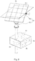
- Fig. 8 is a 3D view of the sun tracking system of an embodiment of the present disclosure.
- the sun tracking system comprises a photovoltaic cell device 81, an attitude control device 82, a short-circuit current sensing device 83, a maximum power tracking control device 84, a motor-driving device 85 and a control unit 86.
- the photovoltaic cell device 81 comprises a plurality of photovoltaic cells 811.
- the attitude control device 82 is adapted to the photovoltaic cell device 81 to control the attitude of the photovoltaic cell device 81.
- the short-circuit current sensing device 83 is coupled to the photovoltaic cell device 81 to sense a short-circuit current of the photovoltaic cell device 81.
- the maximum power tracking control device 84 is coupled to the photovoltaic cell device 81 to track a maximum power of the photovoltaic cell device 81.
- the motor-driving device 85 is adapted to the attitude control device 82 to drive a motor of the attitude control device 82 to change the attitude of the photovoltaic cell device 81.
- the control unit 86 is coupled to the short-circuit current sensing device 83, the maximum power tracking control device 84 and the motor-driving device 85.
- the control unit 86 drives the motor-driving device 85 to further drive the motor of the attitude control device 82 to change the attitude of the photovoltaic cell device 81.
- the short-circuit current sensing device 83 senses and records a short-circuit current of the photovoltaic cell device 81 continuously in cooperation with the switching behavior of the power unit 845 of the maximum power tracking control device 84 when the attitude of the photovoltaic cell device 81 is changing.
- control unit 86 further calculates a maximum value of the recorded short-circuit current to drive the motor-driving device 85 to modulate the attitude of the photovoltaic cell device 81 such that the attitude of the photovoltaic cell device 81 corresponds to the maximum value of the short-circuit current.
- the short-circuit current sensing device 83 senses the short-circuit current without in cooperation with the switching behavior of the power unit of the maximum power tracking control device.
- the switch behavior of the switch unit of the short-circuit current sensing device 83 is only performed when the sun-tracking method is used.
- the frequency of the switch behavior is very high (e.g. over 1000 times per second).
- the short-circuit current sensing device 83 senses and records the short-circuit current of the photovoltaic cell device 81 at the moment when the switch power unit 831 forms the closed circuit.
- control unit 86 further calculates a maximum value of the recorded short-circuit current to drive the motor-driving device 85 to modulate the attitude of the photovoltaic cell device 81 such that the attitude of the photovoltaic cell device 81 corresponds to the maximum value of the short-circuit current.
- the short-circuit current sensing device 83 is not presented.
- the sun-tracking system comprises a photovoltaic cell device 81, an attitude control device 82, a maximum power tracking control device 84, a motor-driving device 85 and a control unit 86.
- the maximum power tracking control device 84 is a voltage up adjusting circuit or a voltage up/down adjusting circuit and is not limited by the circuit form shown in Fig. 8 .
- the maximum power tracking control device 84 comprises a sensing device that senses current, voltage or power.
- control unit 86 further calculates a maximum value of the recorded output power to drive the motor-driving device 85 to modulate the attitude of the photovoltaic cell device 81 such that the attitude of the photovoltaic cell device 81 corresponds to the maximum value of the output power.
- the sun tracking system further comprises a memory (such as a DRAM, not shown) coupled to the control unit 86 to store the values of the short-circuit current each corresponding to a specific attitude of the photovoltaic cell device 81. Therefore, besides the sun tracking process, the sun tracking system of the present disclosure can retrieve the stored values that are stored within a specific time interval (such as one day or one week) for subsequent analysis.
- a memory such as a DRAM, not shown
- each of the plurality of the photovoltaic cells 811 of the photovoltaic cell device 81 is a general photovoltaic cell, a concentrated photovoltaic cell or a highly concentrated photovoltaic cell.
- the attitude control device 82 comprises an azimuth angle control unit 821 and an elevation angle control unit 822.
- Each of the azimuth angle control unit 821 and the elevation angle control unit 822 comprises a control motor (e.g. a DC motor, an AC synchronous motor or a stepping motor) and a speed reducer to control the attitude (comprising the azimuth angle and the elevation angle) of the photovoltaic cell device 81.
- the attitude control device 82 further comprises an azimuth angle limit switch 823 and an elevation angle limit switch 824 to control the displacement distance of the azimuth angle control unit 821 and the elevation angle control unit 822.
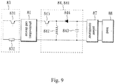
- the short-circuit current sensing device 83 at least comprises a first switch power unit 831 and a current-sensing circuit unit 832.
- the maximum power tracking control device 84 comprises a voltage up/down adjusting circuit unit 841 comprising at least an inductor 842, a capacitor 843, a diode 844 and a second switch power unit 845.
- the photovoltaic cell device 81, the short-circuit current sensing device 83 and the maximum power tracking control device 84 are set as depicted in Fig. 9 .
- the short-circuit current sensing device 83 and the photovoltaic cell device 81 are coupled together while the maximum power tracking control device 84 and the photovoltaic cell device 81 are coupled together on the other end.
- the short-circuit current sensing device 83 and the maximum power tracking control device 84 are integrated as a sensing circuit module (not shown) to connect to the photovoltaic cell device 81.
- the maximum power tracking control device 84 is coupled to a power conditioner (e.g. inverter) 87 and a load 88 to generate an output current to the load 88.
- a power conditioner e.g. inverter
- the first switch power unit 831 in the short-circuit current sensing device 83 and the second switch power unit 845 in the maximum power tracking control device 84 conduct alternatively to alternatively sense and record the short-circuit current of the photovoltaic cell device 81 and to track a maximum power of the photovoltaic cell device 81.
- the sun tracking method is operated in cooperation with the voltage up/down adjusting procedure for tracking the maximum power of the photovoltaic cell device 81 adapted in the maximum power tracking control device 84.
- each of the first switch power unit 831 and the second switch power unit 845 is a MOSFET, a power transistor or an insulated gate bipolar transistor (IGBT).
- the first switch power unit 831 of the short-circuit current sensing device 83 shown in Fig. 9 is not coupled to the second switch power unit 845 of the photovoltaic cell device 81.
- the switch behavior of the first switch power unit 831 of the short-circuit current sensing device 83 is only performed when the sun-tracking method is used.
- the frequency of the switch behavior is very high (e.g. over 1000 times per second).
- the short-circuit current sensing device 83 senses and records the short-circuit current of the photovoltaic cell device 81 at the moment when the first switch power unit 831 forms the closed circuit.
- control unit 86 further calculates a maximum value of the recorded short-circuit current to drive the motor-driving device 85 to modulate the attitude of the photovoltaic cell device 81 such that the attitude of the photovoltaic cell device 81 corresponds to the maximum value of the short-circuit current.
- the short-circuit current sensing device 83 is not presented.
- the maximum power tracking control device 84 is a voltage up adjusting circuit or a voltage up/down adjusting circuit and is not limited by the circuit form shown in Fig. 9 .
- the maximum power tracking control device 84 comprises a sensing device that senses current, voltage or power.
- the control unit 86 further calculates a maximum value of the recorded output power to drive the motor-driving device 85 to modulate the attitude of the photovoltaic cell device 81 such that the attitude of the photovoltaic cell device 81 corresponds to the maximum value of the output power.
- the current-sensing circuit unit 832 of the short-circuit current sensing device 83 sense the short-circuit current of the photovoltaic cell device 81 by a resistive measurement method, a Hall effect measurement method or a CT method.
- the advantage of the resistive measurement method is that it is simple and is suitable for both AC and DC. The disadvantage includes low output voltage, large insertion loss and difficulty of the insulation from the current.
- the CT method is to make the under-test wire pass through a magnetic path.
- a magnetic filed B is generated due to the presence of the current I 0 in the magnetic path to further induce an induced current at the coil on the magnetic path.
- the resistive measurement method described above can further be used to measure the value of the induced current.
- the difference between the CT method and the resistive measurement method is that there is no resistor directly coupled to the current I 0 during the measurement of the induced current.
- the advantage of the CT method includes wider range of application, larger output voltage and the great quality of insulation from the current.
- the Hall effect measurement method is similar to the CT method that makes use of the magnetic field of the magnetic path generated by the presence of the under-measured current.
- the difference between the Hall effect measurement method and the CT method is that a space is presented in the magnetic path when the Hall effect measurement method is adapted to dispose a Hall element in said space.
- the generated magnetic field makes the Hall element generate a Hall voltage that can be measured to further derive the value of the under-measured current.
- the attitude of the photovoltaic cell device 81 is changed according to a search rule.
- the search rule is an AI-based algorithm.
- the Al-based algorithm can be a conventional algorithm such as, but not limited to, a fuzzy algorithm, an ant algorithm, a Taguchi algorithm or a genetic algorithm. Since these algorithms are conventional, no further detail is discussed here.
- the short-circuit current or the output power sensing method in the present disclosure can be used to track the attitude of the photovoltaic cell device that generates the maximum output power and record the difference values of the azimuth angle and the elevation angle as a reference to calibrate the light sensors during the initial setting or after the light sensors are used.
- the method disclosed in the present disclosure can also be performed in cooperation with the conventional tracking method that uses light sensors.
- the conventional tracking method that uses light sensors can be performed to accomplish a rough tracking first and the sun-tracking method of the present disclosure can be used to accomplish a precise tracking later.
- the values of the P-V characteristic curve of the photovoltaic cell device decrease a lot.
- the output current or the output power decreases a lot. Accordingly, whether the sensed short-circuit current or the output power is lower than a certain fixed value is determined first.
- the process of the sun-tracking method of the present disclosure is ceased. Once the short-circuit current or the output power is sensed to be higher than the fixed value, the process of the sun-tracking method of the present disclosure is started again.
- the method disclosed in the present disclosure can also be performed in cooperation with the conventional tracking method that uses solar orbit function.
- the conventional tracking method that uses sun-tracking solar orbit function can use a simple solar orbit function to accomplish a rough tracking first. It is noted that a complex solar orbit function need be implemented in a computer or a PLC but a simple solar orbit function can be implemented in a microprocessor. Afterwards, the sun-tracking method of the present disclosure can be used to accomplish a precise tracking. Furthermore, when clouds block the photovoltaic cell device, the current and the output power is lower than a fixed value. When the short-circuit current or the output power is lower than the fixed value, the process of the sun-tracking method of the present disclosure is ceased and the conventional tracking method that uses solar orbit function can be applied to track the sun. Once the short-circuit current and the output power is sensed to be higher than the fixed value, the process of the sun-tracking method of the present disclosure is started again.
- the short-circuit current of the photovoltaic cell device or the output power varies when the illumination of the light received by the photovoltaic cell device changes (i.e. the value of the short-circuit current of the photovoltaic cell device or the value of the output power corresponds to the illumination of the light received by the photovoltaic cell device).
- the sun tracking method of the present disclosure keeps monitoring the variation of the short-circuit current of the photovoltaic cell device or the output power adapted in the sun tracking system of the present disclosure to make the control unit drive the motor-driving device to further drive the motor of the attitude control device to change the attitude of the photovoltaic cell device until the attitude of the photovoltaic cell device corresponding to the largest short-circuit current is reached.
- the attitude corresponding to the largest short-circuit current or the maximum output power is the attitude that can receive the highest illumination of the sunlight.
- the sun tracking method of the present disclosure makes the sun tracking system of the present disclosure track the sun continuously and switches its position to the attitude that can receive the highest illumination of the sunlight without additional light sensors, calculation of the solar orbit function, regular calibration of the mechanical structure of the sun tracking system regularly or precise initial installation of the sun tracking system.
Landscapes
- Engineering & Computer Science (AREA)
- Physics & Mathematics (AREA)
- Life Sciences & Earth Sciences (AREA)
- Sustainable Development (AREA)
- General Physics & Mathematics (AREA)
- Mechanical Engineering (AREA)
- Chemical & Material Sciences (AREA)
- Combustion & Propulsion (AREA)
- Thermal Sciences (AREA)
- General Engineering & Computer Science (AREA)
- Sustainable Energy (AREA)
- Electromagnetism (AREA)
- Radar, Positioning & Navigation (AREA)
- Remote Sensing (AREA)
- Automation & Control Theory (AREA)
- Photovoltaic Devices (AREA)
- Control Of Position Or Direction (AREA)
Claims (3)
- Sonnengangnachführungsverfahren, das in einem Sonnengangnachführungssystem angepasst ist, das eine Photovoltaikzellenvorrichtung (41), eine Lagesteuervorrichtung (42), eine Kurzschlussstromerfassungsvorrichtung (43), eine Motorantriebsvorrichtung (45) und eine Steuereinheit (46) umfasst, wobei die Kurzschlussstromerfassungsvorrichtung (43) wenigstens eine Schalterleistungseinheit (431) umfasst, dadurch gekennzeichnet ist, dass das Sonnengangnachführungsverfahren umfasst:(A) Antreiben der Motorantriebsvorrichtung (45), um weiterhin einen Motor der Lagesteuervorrichtung (42) anzutreiben, um die Lage der Photovoltaikzellenvorrichtung (41) zu ändern,
Erfassen und Aufzeichnen eines Kurzschlussstroms der Photovoltaikzellenvorrichtung (41) unter Verwendung der Kurzschlussstromerfassungsvorrichtung (43) in einem Moment, in dem die Schalterleistungseinheit (431) einen geschlossenen Stromkreis bildet, um den Kurzschlussstrom der Photovoltaikzellenvorrichtung (41) zu erfassen und aufzuzeichnen;(B) Berechnen eines Maximalwerts des aufgezeichneten Kurzschlussstroms mit der Steuereinheit (46); und(C) Antreiben der Motorantriebsvorrichtung (45), um die Lage der Photovoltaikzellenvorrichtung (41) so zu modulieren, dass die Lage der Photovoltaikzellenvorrichtung (41) dem Maximalwert des Kurzschlussstroms entspricht. - Sonnengangnachführungsverfahren gemäß Anspruch 1, wobei vor Schritt (A), Schritt (B) und Schritt (C) weiterhin einen Schritt zum Durchführen eines Sonnengangnachführungsverfahrens umfassen unter Verwendung einer Sonnengangnachführungs-Sonnenumlauffunktion zum Erreichen einer ersten groben Nachführung, wobei eine präzise Nachführung durch Ausführen von Schritt (A), Schritt (B) und Schritt (C) nach der groben Nachführung erreicht wird.
- Sonnengangnachführverfahren gemäß Anspruch 1, wobei nach Schritt (A) weiterhin umfasst ist, Bestimmen, ob der Kurzschlussstrom niedriger als ein Festwert ist, welcher wenn der Kurzschlussstrom niedriger als der Festwert ist, weiterhin die folgenden Schritte umfasst:Antreiben der Motorantriebsvorrichtung (45) gemäß einer Sonnengangnachführungs-Sonnenumlaufsfunktion;Erfassen des Kurzschlussstroms der Photovoltaikzellenvorrichtung (41); undDurchführen von Schritt (B) und Schritt (C), wenn der Kurzschlussstrom der Photovoltaikzellenvorrichtung (41) größer als der Festwert ist.
Applications Claiming Priority (2)
| Application Number | Priority Date | Filing Date | Title |
|---|---|---|---|
| TW100103086 | 2011-01-27 | ||
| TW100137750A TWI447339B (zh) | 2011-01-27 | 2011-10-18 | 太陽追蹤方法及太陽追蹤系統裝置 |
Publications (3)
| Publication Number | Publication Date |
|---|---|
| EP2482092A2 EP2482092A2 (de) | 2012-08-01 |
| EP2482092A3 EP2482092A3 (de) | 2017-07-12 |
| EP2482092B1 true EP2482092B1 (de) | 2019-07-24 |
Family
ID=45557866
Family Applications (1)
| Application Number | Title | Priority Date | Filing Date |
|---|---|---|---|
| EP12151390.7A Active EP2482092B1 (de) | 2011-01-27 | 2012-01-17 | Sonnennachführungsverfahren |
Country Status (4)
| Country | Link |
|---|---|
| US (1) | US9182471B2 (de) |
| EP (1) | EP2482092B1 (de) |
| JP (1) | JP5626598B2 (de) |
| TW (1) | TWI447339B (de) |
Families Citing this family (44)
| Publication number | Priority date | Publication date | Assignee | Title |
|---|---|---|---|---|
| US20140042296A1 (en) * | 2011-03-03 | 2014-02-13 | Aplicaciones Renovables Integradas, S.L. | Heliostat with a Drive Shaft Pointing at the Target, Reflection Sensor and a Closed-Loop Control System |
| US9236751B2 (en) * | 2012-03-09 | 2016-01-12 | Aspect Solar Pte Ltd | Portable modular sun-tracking solar energy receiver system |
| US9397611B2 (en) * | 2012-03-27 | 2016-07-19 | Sunpower Corporation | Photovoltaic systems with local maximum power point tracking prevention and methods for operating same |
| WO2013158847A1 (en) * | 2012-04-19 | 2013-10-24 | Atonometrics, Inc. | System for field measurement and calibration of photovoltatic reference devices |
| WO2014033707A1 (en) | 2012-08-28 | 2014-03-06 | Ofer Sadka | A system and methods for determination of potential solar installable surface area |
| US10359281B2 (en) | 2012-08-28 | 2019-07-23 | Solview Systems Ltd. | System and method for generating canvas representations reflecting solar installation potential of a geographic area |
| PT106514A (pt) * | 2012-08-31 | 2014-02-28 | Manuel Vieira Lopes | Estrutura automatizada para acolhimento de construções modulares, respectivo sistema de automação e método de funcionamento |
| KR101382417B1 (ko) * | 2012-11-16 | 2014-04-08 | 박기주 | 부유식 태양광 발전 시스템 |
| CN103049004A (zh) * | 2012-12-14 | 2013-04-17 | 华南理工大学 | 一种用于太阳能板的太阳光照射角度跟踪系统 |
| JP5503818B1 (ja) * | 2012-12-25 | 2014-05-28 | パナソニック株式会社 | 太陽追尾装置および方法、太陽光発電装置、ならびに制御装置 |
| JP6213163B2 (ja) * | 2013-01-24 | 2017-10-18 | オムロン株式会社 | パワーコンディショナ、太陽電池システム、および異常判定方法 |
| TWI554859B (zh) * | 2013-04-25 | 2016-10-21 | 鴻海精密工業股份有限公司 | 太陽追蹤裝置及太陽能電池模組 |
| CN103294068A (zh) * | 2013-06-16 | 2013-09-11 | 姬志刚 | 一种太阳能电池板跟踪支架 |
| JP5849191B2 (ja) * | 2013-07-12 | 2016-01-27 | パナソニックIpマネジメント株式会社 | 集光型光電変換装置 |
| CN103353769B (zh) * | 2013-07-16 | 2015-11-11 | 佛山职业技术学院 | 一种基于gps定位的光伏追踪发电方法 |
| CN103412578B (zh) * | 2013-07-22 | 2015-10-28 | 同济大学 | 一种太阳能用黄道跟踪器 |
| CN103676968B (zh) * | 2013-08-28 | 2017-02-08 | 成都谱视科技有限公司 | 太阳跟踪装置 |
| CN103488185B (zh) * | 2013-08-28 | 2016-08-10 | 成都谱视科技有限公司 | 基于云台的太阳跟踪装置 |
| TWI493317B (zh) * | 2014-03-20 | 2015-07-21 | Univ Kun Shan | Solar power generation devices, solar power generation methods, maximum power Tracking module and maximum power tracking control method |
| AU2015235280B2 (en) * | 2014-03-27 | 2017-10-12 | Mitsubishi Power, Ltd. | Heliostat calibration device and heliostat calibration method |
| CN104181940A (zh) * | 2014-08-21 | 2014-12-03 | 四川钟顺太阳能开发有限公司 | 一种基于双轴光伏跟踪系统的过点控制方法 |
| ITUB20153892A1 (it) * | 2015-09-25 | 2017-03-25 | Bwide S R L | Struttura perfezionata di lettino prendisole e relativo metodo di controllo |
| CN106054943B (zh) * | 2016-08-01 | 2023-03-24 | 西部国际绿色能源斯特林(贵州)智能装备制造有限公司 | 一种碟式太阳能跟踪系统的集成化垂直限位保护及定位装置 |
| KR101924783B1 (ko) * | 2016-08-31 | 2018-12-04 | (사)성창에너지연구소 | 브레이크 기능을 가지는 태양광 트랙커 |
| TWI613885B (zh) * | 2017-01-20 | 2018-02-01 | 國立高雄第一科技大學 | 維持同轉速下之直流風扇馬達最佳化節能方法及其晶片 |
| CN107247468A (zh) * | 2017-03-01 | 2017-10-13 | 江苏国电新能源装备有限公司 | 太阳跟踪控制集成电路芯片 |
| US10554172B2 (en) * | 2017-03-09 | 2020-02-04 | Alliance For Sustainable Energy, Llc | Illuminated outdoor luminescence imaging of photovoltaic modules |
| CN109308078B (zh) * | 2017-07-27 | 2021-08-27 | 龙岩智康太阳能科技有限公司 | 定日镜控制方法、装置及计算机可读存储介质和终端设备 |
| CN107544557B (zh) * | 2017-09-21 | 2021-02-19 | 中国十七冶集团有限公司 | 一种基于无线网络的自动跟踪式光伏发电站监控系统 |
| CN108519780A (zh) * | 2018-03-06 | 2018-09-11 | 浙江工贸职业技术学院 | 一种太阳能系统 |
| CN108490983B (zh) * | 2018-05-11 | 2020-03-27 | 中国石油大学(北京) | 一种机械式全季太阳跟踪器 |
| US12587129B2 (en) * | 2018-05-25 | 2026-03-24 | Stracker Incorporated | Elevated dual-axis photovoltaic solar tracking assembly |
| CN108917208B (zh) * | 2018-07-05 | 2020-06-19 | 常州龙腾光热科技股份有限公司 | 一种槽式集热器跟踪方法 |
| US11017561B1 (en) | 2018-10-09 | 2021-05-25 | Heliogen, Inc. | Heliostat tracking based on circumsolar radiance maps |
| TWI698083B (zh) * | 2019-03-19 | 2020-07-01 | 友達光電股份有限公司 | 表面髒污量測方法與量測裝置 |
| US11588425B1 (en) * | 2019-05-16 | 2023-02-21 | Heliogen Holdings, Inc. | System and method for predicting reliability and maintenance of a solar tracker based on varying control torque |
| KR102523202B1 (ko) * | 2020-07-29 | 2023-05-02 | 와이에이치컴퍼니코리아 주식회사 | 전압검출 기반의 룩업 테이블 제어형 태양광 장치 및 방법 |
| CN114460973A (zh) * | 2020-11-09 | 2022-05-10 | 尹梓滔 | 太阳能光伏发电自动跟踪系统及其控制方法 |
| CN112631340A (zh) * | 2020-12-14 | 2021-04-09 | 珠海格力电器股份有限公司 | 光伏组件追踪光源方法及装置 |
| CN113422424B (zh) * | 2021-08-25 | 2021-11-30 | 绵阳天仪空间科技有限公司 | 一种卫星供电系统 |
| CN113922743B (zh) * | 2021-09-17 | 2023-08-25 | 广西英利源盛建设工程有限公司 | 光伏支架自动调节系统 |
| CN114442724B (zh) * | 2021-12-30 | 2023-03-17 | 南京航空航天大学 | 基于光伏电池短路电流估计和扰动观察的最大功率点跟踪方法 |
| US20260088752A1 (en) * | 2024-09-25 | 2026-03-26 | Nextracker Llc | Integrated solar tracker controller and dc/dc converter |
| CN120722960B (zh) * | 2025-08-20 | 2025-11-04 | 山东朝日新能源科技有限公司 | 一种基于霍尔算法及光学视觉辅助对光伏支架的控制方法 |
Family Cites Families (22)
| Publication number | Priority date | Publication date | Assignee | Title |
|---|---|---|---|---|
| JPS6213807A (ja) | 1985-07-10 | 1987-01-22 | Mitsui Constr Co Ltd | 流体圧シリンダ−装置 |
| JPS63181015A (ja) | 1987-01-23 | 1988-07-26 | Kyocera Corp | 太陽光発電装置の最大出力制御方式 |
| JP2003076425A (ja) | 2001-09-05 | 2003-03-14 | Yamazaki Mazak Corp | 送り駆動系の制御装置 |
| JP5013677B2 (ja) | 2005-04-26 | 2012-08-29 | 京セラ株式会社 | 太陽電池制御装置の制御方法 |
| TW200723665A (en) * | 2005-12-07 | 2007-06-16 | Univ Chung Yuan Christian | Impedance matching theory for tracking the maximum power point of the photovoltaic system |
| JP2007231613A (ja) * | 2006-03-01 | 2007-09-13 | Tokyo Electric Power Co Inc:The | ブラインド内蔵複層ガラス装置 |
| US7479774B2 (en) * | 2006-04-07 | 2009-01-20 | Yuan Ze University | High-performance solar photovoltaic (PV) energy conversion system |
| US7507941B2 (en) * | 2006-09-11 | 2009-03-24 | Atomic Energy Council—Institute of Nuclear Energy Research | Hybrid mode sun-tracking apparatus having photo sensor |
| JP4873625B2 (ja) | 2006-10-03 | 2012-02-08 | 行政院原子能委員会核能研究所 | 混合式追跡制御装置付きの光学追跡設備 |
| TW200834023A (en) | 2007-02-09 | 2008-08-16 | Univ Nat Formosa | A light source tracking system |
| US7920942B2 (en) | 2007-03-01 | 2011-04-05 | Wisconsin Alumni Research Foundation | Control of combined storage and generation in distributed energy resources |
| US20080258051A1 (en) | 2007-04-11 | 2008-10-23 | Solfocus, Inc. | Equipment and Process for Measuring the Precision of Sun Tracking for Photovoltaic Concentrators |
| TW200901491A (en) * | 2007-06-28 | 2009-01-01 | Atomic Energy Council | Test device for automatic concentrator solar cell wafer |
| WO2009072075A2 (en) * | 2007-12-05 | 2009-06-11 | Solaredge Technologies Ltd. | Photovoltaic system power tracking method |
| CN101459391A (zh) * | 2007-12-13 | 2009-06-17 | 鸿富锦精密工业(深圳)有限公司 | 光伏控制系统 |
| KR20110014200A (ko) | 2008-05-14 | 2011-02-10 | 내셔널 세미콘덕터 코포레이션 | 지능형 인터버들의 어레이를 위한 시스템 및 방법 |
| US20100018518A1 (en) | 2008-07-24 | 2010-01-28 | Mcdonald Mark | Determination of solar tracking error |
| TWM354725U (en) | 2008-10-09 | 2009-04-11 | Neotec Semiconductor Ltd | An automatic sun tracing system has solar energy plates |
| US20100171482A1 (en) | 2009-01-08 | 2010-07-08 | Yang Ye | Method and apparatus of a maximum power point tracking circuit for solar power generation |
| WO2010085592A2 (en) | 2009-01-22 | 2010-07-29 | Kenneth Oosting | Actuated feedforward controlled solar tracking system |
| TWI409611B (zh) * | 2009-06-30 | 2013-09-21 | Univ Nat Cheng Kung | Maximum power tracking method for solar cells |
| TWI396064B (zh) * | 2009-09-24 | 2013-05-11 | 行政院原子能委員會 核能研究所 | Hcpv演算法結合bipv於直流電力系統之應用裝置 |
-
2011
- 2011-10-18 TW TW100137750A patent/TWI447339B/zh active
-
2012
- 2012-01-17 EP EP12151390.7A patent/EP2482092B1/de active Active
- 2012-01-18 US US13/353,311 patent/US9182471B2/en not_active Expired - Fee Related
- 2012-01-26 JP JP2012014569A patent/JP5626598B2/ja not_active Expired - Fee Related
Non-Patent Citations (1)
| Title |
|---|
| None * |
Also Published As
| Publication number | Publication date |
|---|---|
| EP2482092A2 (de) | 2012-08-01 |
| TWI447339B (zh) | 2014-08-01 |
| JP2012156509A (ja) | 2012-08-16 |
| US9182471B2 (en) | 2015-11-10 |
| EP2482092A3 (de) | 2017-07-12 |
| TW201231898A (en) | 2012-08-01 |
| JP5626598B2 (ja) | 2014-11-19 |
| US20120193512A1 (en) | 2012-08-02 |
Similar Documents
| Publication | Publication Date | Title |
|---|---|---|
| US9182471B2 (en) | Sun tracking method and sun tracking system | |
| US9768725B2 (en) | Redundant electrical architecture for photovoltaic modules | |
| JP5966027B2 (ja) | 不均一な照度に寛容な太陽電池パネルのための光起電力モジュールの電力制御方法 | |
| US7681090B2 (en) | Ripple correlation control based on limited sampling | |
| US7091707B2 (en) | Method and apparatus for controlling power drawn from an energy converter | |
| JP5083425B2 (ja) | 太陽電力変換部の制御装置、及びその制御方法、及び太陽光発電装置 | |
| EP2824533B1 (de) | Photovoltaiksystem | |
| US8816667B2 (en) | Maximum power point tracking method | |
| US20120004874A1 (en) | Maximum power point tracking device for a solar electric generation system and a tracking method for the same | |
| US10651739B1 (en) | Power converters and methods of controlling same | |
| CN103762937A (zh) | 一种mppt光伏变频器控制系统及控制方法 | |
| JP2009247184A (ja) | 太陽光発電システムおよびその起動方法 | |
| CN107172885A (zh) | 最大电力点追踪装置及太阳能电池模块的评估方法 | |
| US9136731B2 (en) | Method and apparatus for controlling a solar panel output in charging a battery | |
| JP5862639B2 (ja) | 太陽電池制御装置 | |
| CN107168447B (zh) | 一种基于改进电导增量法的光伏逆变器多峰值mppt方法 | |
| JP3949350B2 (ja) | 連系装置 | |
| KR101671078B1 (ko) | 태양광 발전 시스템의 최대 전력점 추종 장치 및 방법 | |
| CN102621989A (zh) | 太阳追踪方法及太阳追踪系统装置 | |
| JP2004295688A (ja) | 太陽光発電装置 | |
| KR101929562B1 (ko) | 태양광 발전시스템 | |
| JP5047908B2 (ja) | 最大電力制御装置および最大電力制御方法 | |
| JP2009303310A (ja) | 最大電力スイッチングコンバーター | |
| Okada et al. | Development of a high-speed system measuring a maximum power point of PV modules |
Legal Events
| Date | Code | Title | Description |
|---|---|---|---|
| PUAI | Public reference made under article 153(3) epc to a published international application that has entered the european phase |
Free format text: ORIGINAL CODE: 0009012 |
|
| 17P | Request for examination filed |
Effective date: 20120117 |
|
| AK | Designated contracting states |
Kind code of ref document: A2 Designated state(s): AL AT BE BG CH CY CZ DE DK EE ES FI FR GB GR HR HU IE IS IT LI LT LU LV MC MK MT NL NO PL PT RO RS SE SI SK SM TR |
|
| AX | Request for extension of the european patent |
Extension state: BA ME |
|
| PUAL | Search report despatched |
Free format text: ORIGINAL CODE: 0009013 |
|
| AK | Designated contracting states |
Kind code of ref document: A3 Designated state(s): AL AT BE BG CH CY CZ DE DK EE ES FI FR GB GR HR HU IE IS IT LI LT LU LV MC MK MT NL NO PL PT RO RS SE SI SK SM TR |
|
| AX | Request for extension of the european patent |
Extension state: BA ME |
|
| RIC1 | Information provided on ipc code assigned before grant |
Ipc: G01S 3/786 20060101AFI20170602BHEP Ipc: F24J 2/38 20140101ALI20170602BHEP Ipc: G05D 3/10 20060101ALI20170602BHEP Ipc: F24J 2/54 20060101ALI20170602BHEP |
|
| RBV | Designated contracting states (corrected) |
Designated state(s): AL AT BE BG CH CY CZ DE DK EE ES FI FR GB GR HR HU IE IS IT LI LT LU LV MC MK MT NL NO PL PT RO RS SE SI SK SM TR |
|
| RIC1 | Information provided on ipc code assigned before grant |
Ipc: G01S 3/786 20060101AFI20190130BHEP Ipc: H02S 20/32 20140101ALI20190130BHEP Ipc: H02S 20/00 20140101ALI20190130BHEP Ipc: G05D 3/10 20060101ALI20190130BHEP Ipc: F24S 30/452 20180101ALI20190130BHEP Ipc: F24S 50/20 20180101ALI20190130BHEP |
|
| GRAP | Despatch of communication of intention to grant a patent |
Free format text: ORIGINAL CODE: EPIDOSNIGR1 |
|
| STAA | Information on the status of an ep patent application or granted ep patent |
Free format text: STATUS: GRANT OF PATENT IS INTENDED |
|
| INTG | Intention to grant announced |
Effective date: 20190320 |
|
| GRAS | Grant fee paid |
Free format text: ORIGINAL CODE: EPIDOSNIGR3 |
|
| GRAA | (expected) grant |
Free format text: ORIGINAL CODE: 0009210 |
|
| STAA | Information on the status of an ep patent application or granted ep patent |
Free format text: STATUS: THE PATENT HAS BEEN GRANTED |
|
| AK | Designated contracting states |
Kind code of ref document: B1 Designated state(s): AL AT BE BG CH CY CZ DE DK EE ES FI FR GB GR HR HU IE IS IT LI LT LU LV MC MK MT NL NO PL PT RO RS SE SI SK SM TR |
|
| REG | Reference to a national code |
Ref country code: GB Ref legal event code: FG4D |
|
| REG | Reference to a national code |
Ref country code: CH Ref legal event code: EP |
|
| REG | Reference to a national code |
Ref country code: DE Ref legal event code: R096 Ref document number: 602012062185 Country of ref document: DE |
|
| REG | Reference to a national code |
Ref country code: AT Ref legal event code: REF Ref document number: 1158822 Country of ref document: AT Kind code of ref document: T Effective date: 20190815 |
|
| REG | Reference to a national code |
Ref country code: IE Ref legal event code: FG4D |
|
| REG | Reference to a national code |
Ref country code: NL Ref legal event code: MP Effective date: 20190724 |
|
| REG | Reference to a national code |
Ref country code: LT Ref legal event code: MG4D |
|
| REG | Reference to a national code |
Ref country code: AT Ref legal event code: MK05 Ref document number: 1158822 Country of ref document: AT Kind code of ref document: T Effective date: 20190724 |
|
| PG25 | Lapsed in a contracting state [announced via postgrant information from national office to epo] |
Ref country code: PT Free format text: LAPSE BECAUSE OF FAILURE TO SUBMIT A TRANSLATION OF THE DESCRIPTION OR TO PAY THE FEE WITHIN THE PRESCRIBED TIME-LIMIT Effective date: 20191125 Ref country code: SE Free format text: LAPSE BECAUSE OF FAILURE TO SUBMIT A TRANSLATION OF THE DESCRIPTION OR TO PAY THE FEE WITHIN THE PRESCRIBED TIME-LIMIT Effective date: 20190724 Ref country code: BG Free format text: LAPSE BECAUSE OF FAILURE TO SUBMIT A TRANSLATION OF THE DESCRIPTION OR TO PAY THE FEE WITHIN THE PRESCRIBED TIME-LIMIT Effective date: 20191024 Ref country code: LT Free format text: LAPSE BECAUSE OF FAILURE TO SUBMIT A TRANSLATION OF THE DESCRIPTION OR TO PAY THE FEE WITHIN THE PRESCRIBED TIME-LIMIT Effective date: 20190724 Ref country code: NL Free format text: LAPSE BECAUSE OF FAILURE TO SUBMIT A TRANSLATION OF THE DESCRIPTION OR TO PAY THE FEE WITHIN THE PRESCRIBED TIME-LIMIT Effective date: 20190724 Ref country code: HR Free format text: LAPSE BECAUSE OF FAILURE TO SUBMIT A TRANSLATION OF THE DESCRIPTION OR TO PAY THE FEE WITHIN THE PRESCRIBED TIME-LIMIT Effective date: 20190724 Ref country code: FI Free format text: LAPSE BECAUSE OF FAILURE TO SUBMIT A TRANSLATION OF THE DESCRIPTION OR TO PAY THE FEE WITHIN THE PRESCRIBED TIME-LIMIT Effective date: 20190724 Ref country code: NO Free format text: LAPSE BECAUSE OF FAILURE TO SUBMIT A TRANSLATION OF THE DESCRIPTION OR TO PAY THE FEE WITHIN THE PRESCRIBED TIME-LIMIT Effective date: 20191024 Ref country code: AT Free format text: LAPSE BECAUSE OF FAILURE TO SUBMIT A TRANSLATION OF THE DESCRIPTION OR TO PAY THE FEE WITHIN THE PRESCRIBED TIME-LIMIT Effective date: 20190724 |
|
| PG25 | Lapsed in a contracting state [announced via postgrant information from national office to epo] |
Ref country code: IS Free format text: LAPSE BECAUSE OF FAILURE TO SUBMIT A TRANSLATION OF THE DESCRIPTION OR TO PAY THE FEE WITHIN THE PRESCRIBED TIME-LIMIT Effective date: 20191124 Ref country code: LV Free format text: LAPSE BECAUSE OF FAILURE TO SUBMIT A TRANSLATION OF THE DESCRIPTION OR TO PAY THE FEE WITHIN THE PRESCRIBED TIME-LIMIT Effective date: 20190724 Ref country code: ES Free format text: LAPSE BECAUSE OF FAILURE TO SUBMIT A TRANSLATION OF THE DESCRIPTION OR TO PAY THE FEE WITHIN THE PRESCRIBED TIME-LIMIT Effective date: 20190724 Ref country code: AL Free format text: LAPSE BECAUSE OF FAILURE TO SUBMIT A TRANSLATION OF THE DESCRIPTION OR TO PAY THE FEE WITHIN THE PRESCRIBED TIME-LIMIT Effective date: 20190724 Ref country code: GR Free format text: LAPSE BECAUSE OF FAILURE TO SUBMIT A TRANSLATION OF THE DESCRIPTION OR TO PAY THE FEE WITHIN THE PRESCRIBED TIME-LIMIT Effective date: 20191025 Ref country code: RS Free format text: LAPSE BECAUSE OF FAILURE TO SUBMIT A TRANSLATION OF THE DESCRIPTION OR TO PAY THE FEE WITHIN THE PRESCRIBED TIME-LIMIT Effective date: 20190724 |
|
| PG25 | Lapsed in a contracting state [announced via postgrant information from national office to epo] |
Ref country code: TR Free format text: LAPSE BECAUSE OF FAILURE TO SUBMIT A TRANSLATION OF THE DESCRIPTION OR TO PAY THE FEE WITHIN THE PRESCRIBED TIME-LIMIT Effective date: 20190724 |
|
| PG25 | Lapsed in a contracting state [announced via postgrant information from national office to epo] |
Ref country code: DK Free format text: LAPSE BECAUSE OF FAILURE TO SUBMIT A TRANSLATION OF THE DESCRIPTION OR TO PAY THE FEE WITHIN THE PRESCRIBED TIME-LIMIT Effective date: 20190724 Ref country code: PL Free format text: LAPSE BECAUSE OF FAILURE TO SUBMIT A TRANSLATION OF THE DESCRIPTION OR TO PAY THE FEE WITHIN THE PRESCRIBED TIME-LIMIT Effective date: 20190724 Ref country code: EE Free format text: LAPSE BECAUSE OF FAILURE TO SUBMIT A TRANSLATION OF THE DESCRIPTION OR TO PAY THE FEE WITHIN THE PRESCRIBED TIME-LIMIT Effective date: 20190724 Ref country code: RO Free format text: LAPSE BECAUSE OF FAILURE TO SUBMIT A TRANSLATION OF THE DESCRIPTION OR TO PAY THE FEE WITHIN THE PRESCRIBED TIME-LIMIT Effective date: 20190724 Ref country code: IT Free format text: LAPSE BECAUSE OF FAILURE TO SUBMIT A TRANSLATION OF THE DESCRIPTION OR TO PAY THE FEE WITHIN THE PRESCRIBED TIME-LIMIT Effective date: 20190724 |
|
| PG25 | Lapsed in a contracting state [announced via postgrant information from national office to epo] |
Ref country code: IS Free format text: LAPSE BECAUSE OF FAILURE TO SUBMIT A TRANSLATION OF THE DESCRIPTION OR TO PAY THE FEE WITHIN THE PRESCRIBED TIME-LIMIT Effective date: 20200224 Ref country code: SM Free format text: LAPSE BECAUSE OF FAILURE TO SUBMIT A TRANSLATION OF THE DESCRIPTION OR TO PAY THE FEE WITHIN THE PRESCRIBED TIME-LIMIT Effective date: 20190724 Ref country code: SK Free format text: LAPSE BECAUSE OF FAILURE TO SUBMIT A TRANSLATION OF THE DESCRIPTION OR TO PAY THE FEE WITHIN THE PRESCRIBED TIME-LIMIT Effective date: 20190724 Ref country code: CZ Free format text: LAPSE BECAUSE OF FAILURE TO SUBMIT A TRANSLATION OF THE DESCRIPTION OR TO PAY THE FEE WITHIN THE PRESCRIBED TIME-LIMIT Effective date: 20190724 |
|
| REG | Reference to a national code |
Ref country code: DE Ref legal event code: R097 Ref document number: 602012062185 Country of ref document: DE |
|
| PLBE | No opposition filed within time limit |
Free format text: ORIGINAL CODE: 0009261 |
|
| STAA | Information on the status of an ep patent application or granted ep patent |
Free format text: STATUS: NO OPPOSITION FILED WITHIN TIME LIMIT |
|
| PG2D | Information on lapse in contracting state deleted |
Ref country code: IS |
|
| 26N | No opposition filed |
Effective date: 20200603 |
|
| PG25 | Lapsed in a contracting state [announced via postgrant information from national office to epo] |
Ref country code: SI Free format text: LAPSE BECAUSE OF FAILURE TO SUBMIT A TRANSLATION OF THE DESCRIPTION OR TO PAY THE FEE WITHIN THE PRESCRIBED TIME-LIMIT Effective date: 20190724 Ref country code: MC Free format text: LAPSE BECAUSE OF FAILURE TO SUBMIT A TRANSLATION OF THE DESCRIPTION OR TO PAY THE FEE WITHIN THE PRESCRIBED TIME-LIMIT Effective date: 20190724 |
|
| REG | Reference to a national code |
Ref country code: CH Ref legal event code: PL |
|
| GBPC | Gb: european patent ceased through non-payment of renewal fee |
Effective date: 20200117 |
|
| REG | Reference to a national code |
Ref country code: BE Ref legal event code: MM Effective date: 20200131 |
|
| PG25 | Lapsed in a contracting state [announced via postgrant information from national office to epo] |
Ref country code: GB Free format text: LAPSE BECAUSE OF NON-PAYMENT OF DUE FEES Effective date: 20200117 Ref country code: LU Free format text: LAPSE BECAUSE OF NON-PAYMENT OF DUE FEES Effective date: 20200117 Ref country code: FR Free format text: LAPSE BECAUSE OF NON-PAYMENT OF DUE FEES Effective date: 20200131 |
|
| PG25 | Lapsed in a contracting state [announced via postgrant information from national office to epo] |
Ref country code: BE Free format text: LAPSE BECAUSE OF NON-PAYMENT OF DUE FEES Effective date: 20200131 Ref country code: CH Free format text: LAPSE BECAUSE OF NON-PAYMENT OF DUE FEES Effective date: 20200131 Ref country code: LI Free format text: LAPSE BECAUSE OF NON-PAYMENT OF DUE FEES Effective date: 20200131 |
|
| PG25 | Lapsed in a contracting state [announced via postgrant information from national office to epo] |
Ref country code: IE Free format text: LAPSE BECAUSE OF NON-PAYMENT OF DUE FEES Effective date: 20200117 |
|
| PGFP | Annual fee paid to national office [announced via postgrant information from national office to epo] |
Ref country code: DE Payment date: 20210119 Year of fee payment: 10 |
|
| PG25 | Lapsed in a contracting state [announced via postgrant information from national office to epo] |
Ref country code: MT Free format text: LAPSE BECAUSE OF FAILURE TO SUBMIT A TRANSLATION OF THE DESCRIPTION OR TO PAY THE FEE WITHIN THE PRESCRIBED TIME-LIMIT Effective date: 20190724 Ref country code: CY Free format text: LAPSE BECAUSE OF FAILURE TO SUBMIT A TRANSLATION OF THE DESCRIPTION OR TO PAY THE FEE WITHIN THE PRESCRIBED TIME-LIMIT Effective date: 20190724 |
|
| PG25 | Lapsed in a contracting state [announced via postgrant information from national office to epo] |
Ref country code: MK Free format text: LAPSE BECAUSE OF FAILURE TO SUBMIT A TRANSLATION OF THE DESCRIPTION OR TO PAY THE FEE WITHIN THE PRESCRIBED TIME-LIMIT Effective date: 20190724 |
|
| REG | Reference to a national code |
Ref country code: DE Ref legal event code: R119 Ref document number: 602012062185 Country of ref document: DE |
|
| PG25 | Lapsed in a contracting state [announced via postgrant information from national office to epo] |
Ref country code: DE Free format text: LAPSE BECAUSE OF NON-PAYMENT OF DUE FEES Effective date: 20220802 |