EP2481935A1 - Verfahren zum Montieren eines Bauteils und Befestigungsclip - Google Patents
Verfahren zum Montieren eines Bauteils und Befestigungsclip Download PDFInfo
- Publication number
- EP2481935A1 EP2481935A1 EP12000206A EP12000206A EP2481935A1 EP 2481935 A1 EP2481935 A1 EP 2481935A1 EP 12000206 A EP12000206 A EP 12000206A EP 12000206 A EP12000206 A EP 12000206A EP 2481935 A1 EP2481935 A1 EP 2481935A1
- Authority
- EP
- European Patent Office
- Prior art keywords
- code
- release
- fastening clip
- assembly position
- head
- Prior art date
- Legal status (The legal status is an assumption and is not a legal conclusion. Google has not performed a legal analysis and makes no representation as to the accuracy of the status listed.)
- Granted
Links
Images


Classifications
-
- B—PERFORMING OPERATIONS; TRANSPORTING
- B60—VEHICLES IN GENERAL
- B60R—VEHICLES, VEHICLE FITTINGS, OR VEHICLE PARTS, NOT OTHERWISE PROVIDED FOR
- B60R13/00—Elements for body-finishing, identifying, or decorating; Arrangements or adaptations for advertising purposes
- B60R13/02—Internal Trim mouldings ; Internal Ledges; Wall liners for passenger compartments; Roof liners
- B60R13/0206—Arrangements of fasteners and clips specially adapted for attaching inner vehicle liners or mouldings
-
- B—PERFORMING OPERATIONS; TRANSPORTING
- B60—VEHICLES IN GENERAL
- B60R—VEHICLES, VEHICLE FITTINGS, OR VEHICLE PARTS, NOT OTHERWISE PROVIDED FOR
- B60R16/00—Electric or fluid circuits specially adapted for vehicles and not otherwise provided for; Arrangement of elements of electric or fluid circuits specially adapted for vehicles and not otherwise provided for
- B60R16/02—Electric or fluid circuits specially adapted for vehicles and not otherwise provided for; Arrangement of elements of electric or fluid circuits specially adapted for vehicles and not otherwise provided for electric constitutive elements
-
- B—PERFORMING OPERATIONS; TRANSPORTING
- B60—VEHICLES IN GENERAL
- B60R—VEHICLES, VEHICLE FITTINGS, OR VEHICLE PARTS, NOT OTHERWISE PROVIDED FOR
- B60R21/00—Arrangements or fittings on vehicles for protecting or preventing injuries to occupants or pedestrians in case of accidents or other traffic risks
- B60R21/02—Occupant safety arrangements or fittings, e.g. crash pads
- B60R21/16—Inflatable occupant restraints or confinements designed to inflate upon impact or impending impact, e.g. air bags
- B60R21/20—Arrangements for storing inflatable members in their non-use or deflated condition; Arrangement or mounting of air bag modules or components
- B60R21/217—Inflation fluid source retainers, e.g. reaction canisters; Connection of bags, covers, diffusers or inflation fluid sources therewith or together
-
- B—PERFORMING OPERATIONS; TRANSPORTING
- B62—LAND VEHICLES FOR TRAVELLING OTHERWISE THAN ON RAILS
- B62D—MOTOR VEHICLES; TRAILERS
- B62D25/00—Superstructure or monocoque structure sub-units; Parts or details thereof not otherwise provided for
-
- F—MECHANICAL ENGINEERING; LIGHTING; HEATING; WEAPONS; BLASTING
- F16—ENGINEERING ELEMENTS AND UNITS; GENERAL MEASURES FOR PRODUCING AND MAINTAINING EFFECTIVE FUNCTIONING OF MACHINES OR INSTALLATIONS; THERMAL INSULATION IN GENERAL
- F16B—DEVICES FOR FASTENING OR SECURING CONSTRUCTIONAL ELEMENTS OR MACHINE PARTS TOGETHER, e.g. NAILS, BOLTS, CIRCLIPS, CLAMPS, CLIPS OR WEDGES; JOINTS OR JOINTING
- F16B19/00—Bolts without screw-thread; Pins, including deformable elements; Rivets
- F16B19/04—Rivets; Spigots or the like fastened by riveting
- F16B19/08—Hollow rivets; Multi-part rivets
- F16B19/10—Hollow rivets; Multi-part rivets fastened by expanding mechanically
- F16B19/1027—Multi-part rivets
- F16B19/1036—Blind rivets
- F16B19/1081—Blind rivets fastened by a drive-pin
-
- F—MECHANICAL ENGINEERING; LIGHTING; HEATING; WEAPONS; BLASTING
- F16—ENGINEERING ELEMENTS AND UNITS; GENERAL MEASURES FOR PRODUCING AND MAINTAINING EFFECTIVE FUNCTIONING OF MACHINES OR INSTALLATIONS; THERMAL INSULATION IN GENERAL
- F16B—DEVICES FOR FASTENING OR SECURING CONSTRUCTIONAL ELEMENTS OR MACHINE PARTS TOGETHER, e.g. NAILS, BOLTS, CIRCLIPS, CLAMPS, CLIPS OR WEDGES; JOINTS OR JOINTING
- F16B2/00—Friction-grip releasable fastenings
- F16B2/20—Clips, i.e. with gripping action effected solely by the inherent resistance to deformation of the material of the fastening
-
- F—MECHANICAL ENGINEERING; LIGHTING; HEATING; WEAPONS; BLASTING
- F16—ENGINEERING ELEMENTS AND UNITS; GENERAL MEASURES FOR PRODUCING AND MAINTAINING EFFECTIVE FUNCTIONING OF MACHINES OR INSTALLATIONS; THERMAL INSULATION IN GENERAL
- F16B—DEVICES FOR FASTENING OR SECURING CONSTRUCTIONAL ELEMENTS OR MACHINE PARTS TOGETHER, e.g. NAILS, BOLTS, CIRCLIPS, CLAMPS, CLIPS OR WEDGES; JOINTS OR JOINTING
- F16B21/00—Means for preventing relative axial movement of a pin, spigot, shaft or the like and a member surrounding it; Stud-and-socket releasable fastenings
- F16B21/06—Releasable fastening devices with snap-action
- F16B21/065—Releasable fastening devices with snap-action with an additional locking element
-
- F—MECHANICAL ENGINEERING; LIGHTING; HEATING; WEAPONS; BLASTING
- F16—ENGINEERING ELEMENTS AND UNITS; GENERAL MEASURES FOR PRODUCING AND MAINTAINING EFFECTIVE FUNCTIONING OF MACHINES OR INSTALLATIONS; THERMAL INSULATION IN GENERAL
- F16B—DEVICES FOR FASTENING OR SECURING CONSTRUCTIONAL ELEMENTS OR MACHINE PARTS TOGETHER, e.g. NAILS, BOLTS, CIRCLIPS, CLAMPS, CLIPS OR WEDGES; JOINTS OR JOINTING
- F16B5/00—Joining sheets or plates, e.g. panels, to one another or to strips or bars parallel to them
- F16B5/06—Joining sheets or plates, e.g. panels, to one another or to strips or bars parallel to them by means of clamps or clips
- F16B5/0685—Joining sheets or plates to strips or bars
-
- F—MECHANICAL ENGINEERING; LIGHTING; HEATING; WEAPONS; BLASTING
- F16—ENGINEERING ELEMENTS AND UNITS; GENERAL MEASURES FOR PRODUCING AND MAINTAINING EFFECTIVE FUNCTIONING OF MACHINES OR INSTALLATIONS; THERMAL INSULATION IN GENERAL
- F16B—DEVICES FOR FASTENING OR SECURING CONSTRUCTIONAL ELEMENTS OR MACHINE PARTS TOGETHER, e.g. NAILS, BOLTS, CIRCLIPS, CLAMPS, CLIPS OR WEDGES; JOINTS OR JOINTING
- F16B21/00—Means for preventing relative axial movement of a pin, spigot, shaft or the like and a member surrounding it; Stud-and-socket releasable fastenings
- F16B21/06—Releasable fastening devices with snap-action
- F16B21/07—Releasable fastening devices with snap-action in which the socket has a resilient part
- F16B21/076—Releasable fastening devices with snap-action in which the socket has a resilient part the socket having a resilient part on its outside
-
- F—MECHANICAL ENGINEERING; LIGHTING; HEATING; WEAPONS; BLASTING
- F16—ENGINEERING ELEMENTS AND UNITS; GENERAL MEASURES FOR PRODUCING AND MAINTAINING EFFECTIVE FUNCTIONING OF MACHINES OR INSTALLATIONS; THERMAL INSULATION IN GENERAL
- F16B—DEVICES FOR FASTENING OR SECURING CONSTRUCTIONAL ELEMENTS OR MACHINE PARTS TOGETHER, e.g. NAILS, BOLTS, CIRCLIPS, CLAMPS, CLIPS OR WEDGES; JOINTS OR JOINTING
- F16B21/00—Means for preventing relative axial movement of a pin, spigot, shaft or the like and a member surrounding it; Stud-and-socket releasable fastenings
- F16B21/06—Releasable fastening devices with snap-action
- F16B21/08—Releasable fastening devices with snap-action in which the stud, pin, or spigot has a resilient part
- F16B21/086—Releasable fastening devices with snap-action in which the stud, pin, or spigot has a resilient part the shank of the stud, pin or spigot having elevations, ribs, fins or prongs intended for deformation or tilting predominantly in a direction perpendicular to the direction of insertion
-
- F—MECHANICAL ENGINEERING; LIGHTING; HEATING; WEAPONS; BLASTING
- F16—ENGINEERING ELEMENTS AND UNITS; GENERAL MEASURES FOR PRODUCING AND MAINTAINING EFFECTIVE FUNCTIONING OF MACHINES OR INSTALLATIONS; THERMAL INSULATION IN GENERAL
- F16B—DEVICES FOR FASTENING OR SECURING CONSTRUCTIONAL ELEMENTS OR MACHINE PARTS TOGETHER, e.g. NAILS, BOLTS, CIRCLIPS, CLAMPS, CLIPS OR WEDGES; JOINTS OR JOINTING
- F16B2200/00—Constructional details of connections not covered for in other groups of this subclass
- F16B2200/95—Constructional details of connections not covered for in other groups of this subclass with markings, colours, indicators or the like
-
- F—MECHANICAL ENGINEERING; LIGHTING; HEATING; WEAPONS; BLASTING
- F16—ENGINEERING ELEMENTS AND UNITS; GENERAL MEASURES FOR PRODUCING AND MAINTAINING EFFECTIVE FUNCTIONING OF MACHINES OR INSTALLATIONS; THERMAL INSULATION IN GENERAL
- F16B—DEVICES FOR FASTENING OR SECURING CONSTRUCTIONAL ELEMENTS OR MACHINE PARTS TOGETHER, e.g. NAILS, BOLTS, CIRCLIPS, CLAMPS, CLIPS OR WEDGES; JOINTS OR JOINTING
- F16B5/00—Joining sheets or plates, e.g. panels, to one another or to strips or bars parallel to them
- F16B5/12—Fastening strips or bars to sheets or plates, e.g. rubber strips, decorative strips for motor vehicles, by means of clips
- F16B5/123—Auxiliary fasteners specially designed for this purpose
- F16B5/125—Auxiliary fasteners specially designed for this purpose one of the auxiliary fasteners is comprising wire or sheet material or is made thereof
-
- Y—GENERAL TAGGING OF NEW TECHNOLOGICAL DEVELOPMENTS; GENERAL TAGGING OF CROSS-SECTIONAL TECHNOLOGIES SPANNING OVER SEVERAL SECTIONS OF THE IPC; TECHNICAL SUBJECTS COVERED BY FORMER USPC CROSS-REFERENCE ART COLLECTIONS [XRACs] AND DIGESTS
- Y10—TECHNICAL SUBJECTS COVERED BY FORMER USPC
- Y10T—TECHNICAL SUBJECTS COVERED BY FORMER US CLASSIFICATION
- Y10T24/00—Buckles, buttons, clasps, etc.
- Y10T24/44—Clasp, clip, support-clamp, or required component thereof
- Y10T24/44966—Clasp, clip, support-clamp, or required component thereof having gripping member shifted by operator
-
- Y—GENERAL TAGGING OF NEW TECHNOLOGICAL DEVELOPMENTS; GENERAL TAGGING OF CROSS-SECTIONAL TECHNOLOGIES SPANNING OVER SEVERAL SECTIONS OF THE IPC; TECHNICAL SUBJECTS COVERED BY FORMER USPC CROSS-REFERENCE ART COLLECTIONS [XRACs] AND DIGESTS
- Y10—TECHNICAL SUBJECTS COVERED BY FORMER USPC
- Y10T—TECHNICAL SUBJECTS COVERED BY FORMER US CLASSIFICATION
- Y10T29/00—Metal working
- Y10T29/49—Method of mechanical manufacture
- Y10T29/49826—Assembling or joining
- Y10T29/49947—Assembling or joining by applying separate fastener
Definitions
- the invention relates to a method for mounting a component by means of a fastening clip and a fastening clip.
- Fixing clips are used to fix attachments to a vehicle body quickly and safely.
- the fastening clip has, for example, a latching section, which is inserted into a vehicle opening and latched therein, and a head element, which is inserted into the latching section.
- the component to be fastened (for example a trim part or a gas bag module) is fixed either directly by means of the latching section, for example if this is designed as a fastening clip, or on a body which is provided on the latching section, for example if this is designed as a dowel.
- the component to be fastened can also be fastened to the head element.
- a two-part fastening clip of the locking portion and the head element are provided with complementary locking elements, which are brought by a sliding movement with each other.
- the head element In the retracted final assembly position, the head element also prevents the catch portion from being pulled out of the opening of the vehicle body.
- the fastening clip can be handled as a single component.
- the latching portion in the opening on the Vehicle body can be used, and the component to be fastened can be fixed to the mounting clip.
- the head element is then brought from its pre-assembly position into the final assembly position.
- a one-piece fastening clip locking portion and head are integrally connected.
- the head element is loaded in the direction of insertion to lock the locking portion in the opening.
- the pre-assembly position corresponds to a position in which the latching section is not yet or not yet fully inserted into the opening.
- the object of the invention is to allow a documentation of the correct attachment of a mounting clip in a simple manner.
- this is achieved by mounting a component by means of a fastening clip which has a latching section and a head element, which is brought from a pre-assembly position into a final assembly position for mounting the component, wherein a release element is provided on the fastening clip, which can be moved from a first position, in which a machine-readable code attached to the mounting clip is not readable, is brought into a second position in which the code is read when the head element is brought into the final assembly position. Only when the mounting clip is in its final assembly position can the machine-readable code be read correctly by a reader. In the pre-assembly position, on the other hand, the release element prevents the code from being read out, that is, from being recognized correctly.
- the ability to read the code depends on a specific reading position in relation to the mounting clip.
- the mounting clip is formed so that the reading position is preferably fixed with respect to a specific mounting clip, so the reader is not moved relative to the mounting clip, but is held in a fixed position relative to the mounting clip. With respect to such a predetermined reading position, the code can only be read when the head element is in the final assembly position.
- the release element so that the code is complete only in the second position. Then the reading position is variable in that the code can be read in any position in which it lies within the field of view of the reader.
- the method is preferably carried out for all mounting clips to be installed in a single operation, wherein for each fastening clip it is detected and recorded whether a code could be read.
- the invention also relates to a fastening clip which can be used in particular in a method just described.
- the mounting clip has a catch portion and a head member, and may be brought from the preassembly position to a final assembly position, wherein a machine-readable code and a release member are coupled to the head member so that it moves in the final assembly position upon movement of the head member becomes.
- the release element is in the preassembly position in a first position in which the code is not readable, and in the final assembly position in a second position in which the code is readable.
- the readability (detectability) of the code thus depends on the mounting position of the mounting clip.
- the mechanical movement of the release part which is caused for example by the relative movement of the head element and locking portion or by a relative movement of the mounting clip against a vehicle-mounted component, causes the code is released and by a Reader can be read and recognized from a predetermined reading position.
- a code is understood here to mean a complete sequence of coding characters which contains the entire meaning of the encoded information.
- the code used is preferably a barcode.
- Barcodes consist of a sequence of parallel bars and gaps of different widths. This type of code can be easily and inexpensively applied to various surfaces and encode any information. Barcode readers are available in a variety of training, they are reliable and cheap.
- the code may be printed, glued or embossed, for example, directly on one or more of the mutually movable components of the mounting clip or on an associated component.
- At least a portion of the code is mounted on the release element itself.
- the release element advantageously changes its spatial position and / or its orientation relative to the latching section or the head element when the head element is moved into the final assembly position.
- the release element may be a plate which is movably connected to the head element.
- the release member extends in the first position at an acute angle to a longitudinal axis of the head member, and in a movement along the longitudinal axis for moving the head member from the pre-assembly to the final assembly position, the angle between the release member and the longitudinal axis increased.
- the movement of the release element can in each case be effected in that it comes into contact with a part of the fastening clip or a vehicle-fixed component.
- the release element may extend, for example, in the first position at an angle to the code base element, whereas in the second position, the release element and the code base element preferably lie in one plane.
- the pre-assembly position due to the angle between the two code sections, a part of the code is not detected at all or with smaller distances between the individual bar code bars.
- the reader is advantageously set so that it detects this deviation and rejects the code as unreadable. Only if a certain angle between the two code sections is reached and preferably both code sections lie in one plane, the code is recognized.
- the release element is a masking plate which, in the first position, covers a portion of the code.
- the code in the first position can not be read completely, but only when the masking plate has been moved in the second position so that the entire code is exposed to the reader.
- the masking plate may have a window that only gives the reader the view of the entire code when the head element is in the final assembly position and thus the release element is in the second position.
- the masking plate is coupled to the head member so that it is remote from the code in the second position.
- the masking plate is pulled away by the movement of the head element from the code base element, so that it is exposed in the second position relative to the reading device.
- the masking plate can be pulled, for example, in a space between the latching portion and the head element. It is also possible that the masking plate breaks off during the movement of the head element.
- the code may be configured to allow unique identification of the fastener.
- certain codes may be used to attach certain components, such as a side airbag, to a roof frame.
- the movement of the head element from the pre-assembly position into the final assembly position can be effected by a linear movement in the direction of the longitudinal axis of the head element.
- the movement into the final assembly position takes place by means of a rotation.
- the individual code sections may initially be arranged in a plane at an angle to one another and be aligned linearly in the second position, so that the code can be read.
- FIG. 1 shows a mounting clip 100 which serves to attach a component to a vehicle body.
- the fastening clip 100 is constructed in two parts and has a holding part 102 and a head element 104.
- the holding part 102 has a latching portion 106 which is in an in FIG. 1 indicated opening can be inserted in the vehicle body and locked there, so it can be fixed so that it is firmly anchored there in the usually acting forces.
- a receptacle 108 is formed on the holding part 102, which is here shaped so that a side airbag packet pushed through and can be connected to the mounting clip 100.
- the holding part 102 in particular the receptacle 108, but could also be designed for fixing any other component.
- the head element 104 and the holding part 102 are movable relative to each other in an insertion direction E.
- the head element 104 Before fastening the fastening clip 100 to the vehicle, the head element 104 is in a pre-assembly position (FIG. FIG. 1 ), in which the head member 104 and the holding part 102 are connected to each other, but the locking portion 106 of the holding part 102 can still be inserted into an opening.
- the head member 104 After the holding member 102 has been inserted with its latching portion 106 in the opening, the head member 104 is moved from the pre-assembly to the final assembly position for final assembly.
- the head member 104 has a spreading portion 110 which cooperates with the locking portion 106 of the holding part 102, so that, for example, the locking elements on the locking portion 106, which fix the holding part 102 at the edge of the opening, spread apart or prevented from squeezing. In this state, the fixing clip 100 can not be removed from the opening.
- fastening clips are known in many forms and are used in many ways. For the present invention it is immaterial what type of fastening clip it is. It is only important that the two parts of the mounting clip initially in a pre-assembly and only in the final attachment to the vehicle in a final assembly position, wherein the head member 104 relative to the holding part 102 and the latching portion 106th takes a different position.
- the insertion direction E can, as in the examples shown here, lie linearly in the direction of the longitudinal axis of the head element 104.
- FIGS. 1 and 2 show the mounting clip 100 with the header 104 in the preassembly position
- FIGS. 3 and 4 the fastening clip 100 with the head element 104 in the final assembly position.
- a plurality of fastening clips are first fixed on the component to be fastened. Then the fastening clips are inserted into openings of the vehicle body. As a last step, the fastening clips are fixed to the vehicle body by bringing the head elements of the fastening clips from the pre-assembly position into the final assembly position. Only now is the component to be fastened securely fastened to the vehicle body.
- a release element 112 is provided on the fastening clip 100, which is coupled to the head element 104.
- the release member 112 moves from a first position, which holds it, when the head member 104 is in the preassembly position, to a second position, which it assumes when the head member 104 in the final assembly position is.
- a machine-readable code 114 is arranged, which is read by a reading device 116 from a predetermined reading position (indicated in FIG. 3 ) can be recorded and read.
- the reading direction is in the embodiments shown here parallel to the insertion direction E.
- the code 114 is here in each case a barcode, which in this case is glued to the release element 112, printed or embossed into it.
- the release element 112 ensures that the code 114 can not be read when the release element 112 is in the first position, but instead only when the head member 104 is in the final assembly position and the release member 112 is in the second position.
- the in the FIGS. 1 to 4 utilizes a release member 112 which, when moving from the first to the second position, alters its orientation, in this case its angle to the longitudinal axis of the head member 104.
- the release member 112 here in the form of an elongated plate and pivotally hinged to an indentation portion 118 of the head member 104, extends at an acute angle to the direction of insertion E. From the predetermined reading position of the reader 116, the result the code 114 in the in FIG. 2 represented form.
- the reader 116 detects that the distances of the individual bars of the barcode below a predetermined minimum distance, so that the code can not be resolved. Attempting to attach the code 114 to the mounting clip 100 in the in FIGS. 1 and 2 read position shown in the release member 112 is in the first position, the reader 116 outputs an error message.
- the release element 112 By pushing down the indentation section 118 of the head element 104 in the insertion direction E, the release element 112 is pivoted due to the contact with the body of the holding part 102, so that the angle relative to the insertion direction E increases. In the example shown here is complete inserted head 104 (correct final assembly position) the release element 112 in a plane with the Eind Wegabêt 118. If now read by the reader 116, the code 114, this is successful, and the read code and the confirmation of the successful reading operation in the reader 116th saved.
- the code 114 is completely mounted on the release element 112.
- FIGS. 5 to 8 a second embodiment of a fastening clip 200 is shown.
- the holding part 102 is substantially identical in construction to the holding part of the first embodiment, so that the already introduced reference numerals are retained here.
- FIGS. 5 and 6 show the fastening clip 200 in the preassembly position of the head element 204, while the FIGS. 7 and 8 illustrate the attachment clip 200 with the header 204 in the final assembly position.
- the plate-shaped release element 212 is designed in the form of a masking plate, which has a window 220.
- the code 114 in this case is applied to a flat portion of the support member 102 with the code 114 and the window 220 in the release member 212 aligned with each other such that when attempting to read by the reader 116 (shown only in the first embodiment), which is at the same predetermined reading position as in the first embodiment, can only recognize a part of the code 114 which is not sufficient for a successful reading of the code 114.
- the reader 116 is in this case ( FIGS. 5 and 6 ), in which the release element 212 is in the first position, issue an error message.
- the window 220 is above the code 114 so that it is completely detectable by the reader 116.
- Release member 212 is attached.
- the two sections of the code 114 then complement each other in the second position of the release element to the complete code 114 and can only be read in this by the reader 116.
- the code 114 may be read when the reader 116 is in a position to capture the code 114.
- the predetermined reading position is therefore variable within a certain frame.
- FIGS. 9 to 12 a third embodiment of a fastening clip 300 is shown.
- the holding part 302 is designed as a generally V-shaped locking clip, wherein the locking portions 306 are designed as shoulders on the outer surfaces of the locking clip.
- the head element 304 with executed as insertion part, which can be inserted into the locking clip. In this case too, the head element 304 is moved out of its position in the direction of insertion E by a linear movement in the direction of insertion E (in the case of the figures, vertically downward)
- FIGS. 9 and 10 shown pre-assembly position in the in FIGS. 11 and 12 transferred shown final assembly position.
- a first portion of the code 114 in the form of a code base 322 is disposed on the indentation portion 318 of the header 304.
- a release member 312 each in the form of a plate is connected to the indenting portion 318 by means of a film hinge as in the first embodiment.
- Each of the two release elements 312 carries a further portion of the code 114.
- the code 114 may be read by the reader 116.
- a fixing clip 400 is shown whose basic shape substantially corresponds to that of the fixing clip 300 of the third embodiment.
- the entire code 114 is mounted on a flat portion of the holding part 402.
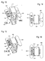
- Two release elements 412 in the form of narrow webs are coupled via film hinges to the head element 404 and lie in the first position (FIG. FIGS. 13 and 14 ) on the holding part 402 so as to cover portions of the code 114.
- a reading attempt from the predetermined reading position thus results in an error message because not the entire code 114 is visible.
- the release elements 412 are pulled into a gap 424 between the holding part 402 and the head element 404 and thus removed from the code 114.
- the code 114 is thus completely free and can be read and the mounting clip 400 can be documented as correctly mounted.
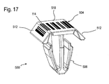
- FIG. 17 a fifth embodiment of a fastening clip 500 is shown.
- the fastening clip 500 is formed in one piece, so that the head element 504 merges into the latching section 506. Head element 504 and latching portion 506 are not movable relative to each other.
- a release element 512 is articulated on two opposite sides of a push-in section 518 of the head element 504. Both the push-in section 518 and both release elements 512 each carry a code section.
- the code portions on the release members 512 are brought into contact with the vehicle body or other vehicle-fixed member into a plane with the code portion of the push-in portion 518.
- the code 114 may be read by the reader 116 when the reader 116 detects the code 114.
- a machine-readable code to a mounting clip so that is released when moving a release part from a first to a second position of the code for a reader.
- a head element can be used, which is brought by rotation about its axis from the pre-assembly position to the final assembly position.
- the code can be divided into two parts, which are merged by turning the header to a readable total code.
Landscapes
- Engineering & Computer Science (AREA)
- General Engineering & Computer Science (AREA)
- Mechanical Engineering (AREA)
- Chemical & Material Sciences (AREA)
- Combustion & Propulsion (AREA)
- Transportation (AREA)
- Air Bags (AREA)
- Connection Of Plates (AREA)
- Clamps And Clips (AREA)
- Supply And Installment Of Electrical Components (AREA)
Abstract
Description
- Die Erfindung betrifft ein Verfahren zum Montieren eines Bauteils mittels eines Befestigungsclips sowie einen Befestigungsclip.
- Befestigungsclips werden eingesetzt, um an einer Fahrzeugkarosserie Anbauteile schnell und sicher zu fixieren. Der Befestigungsclip weist beispielsweise einen Rastabschnitt auf, der in eine Fahrzeugöffnung eingeschoben wird und in dieser verrastet, und ein Kopfelement, das in den Rastabschnitt eingeschoben wird. Das zu befestigende Bauteil (z.B. ein Verkleidungsteil oder ein Gassack-Modul) ist entweder direkt mittels des Rastabschnittes fixiert, beispielsweise wenn dieser als Befestigungsklammer ausgeführt ist, oder an einem Körper, der am Rastabschnitt vorgesehen ist, beispielsweise wenn dieser als Dübel ausgeführt ist. Das zu befestigende Bauteil kann auch am Kopfelement befestigt sein.
- Bei einem zweiteilig ausgeführten Befestigungsclip sind der Rastabschnitt und das Kopfelement mit komplementären Rastelementen versehen, die durch eine Einschubbewegung miteinander in Eingriff gebracht werden. In der eingeschobenen Endmontageposition verhindert das Kopfelement auch, dass der Rastabschnitt aus der Öffnung der Fahrzeugkarosserie wieder herausgezogen werden kann.
- Es ist bekannt, den Rastabschnitt und das Kopfelement zur einfacheren Verarbeitung aneinander in einer Vormontageposition vorzufixieren, sodass der Befestigungsclip als ein einziges Bauteil gehandhabt werden kann. In der Vormontageposition kann der Rastabschnitt in die Öffnung an der Fahrzeugkarosserie eingesetzt werden, und das zu befestigende Bauteil kann am Befestigungsclip fixiert werden. Zur endgültigen Fixierung des Befestigungsclips an der Fahrzeugkarosserie wird dann das Kopfelement aus seiner Vormontageposition in die Endmontageposition gebracht.
- Bei einem einteilig ausgeführten Befestigungsclip sind Rastabschnitt und Kopfelement einstückig miteinander verbunden. Das Kopfelement wird in Einschubrichtung belastet, um den Rastabschnitt in der Öffnung zu verrasten.
- Die Vormontageposition entspricht in diesem Fall einer Position, in der der Rastabschnitt noch nicht oder noch nicht vollständig in die Öffnung eingeschoben ist.
- Derartige Befestigungsclips werden in größerer Anzahl und oft an schwer einsehbaren Stellen im Fahrzeug verbaut. Ein Beleg dafür, dass sämtliche Befestigungsclips korrekt in der Endmontageposition verriegelt wurden, ist wünschenswert, aber aufwendig.
- Aufgabe der Erfindung ist es, eine Dokumentation der korrekten Befestigung eines Befestigungsclips auf einfache Weise zu ermöglichen.
- Erfindungsgemäß wird dies erreicht, indem ein Bauteils mittels eines Befestigungsclips montiert wird, der einen Rastabschnitt und ein Kopfelement aufweist, das zur Montage des Bauteils aus einer Vormontageposition in eine Endmontageposition gebracht wird, wobei am Befestigungsclip ein Freigabeelement vorgesehen ist, das aus einer ersten Stellung, in der ein am Befestigungsclip angebrachter maschinenlesbarer Code nicht ablesbar ist, in eine zweite Stellung gebracht wird, in der der Code ablesbar ist, wenn das Kopfelement in die Endmontageposition gebracht wird. Nur wenn der Befestigungsclip in seiner Endmontageposition ist, kann der maschinenlesbare Code von einem Lesegerät korrekt gelesen werden. In der Vormontageposition hingegen verhindert das Freigabeelement, dass der Code abgelesen, also korrekt erkannt werden kann. Da jedes Ablesen, hier gleichgesetzt mit Erkennen, eines Codes bedeutet, dass der Befestigungsclip korrekt montiert wurde, lässt sich über den abgelesenen Code auch dokumentieren, dass der Befestigungsclip korrekt verbaut wurde. Das Verfahren stellt demnach eine einfache Kontrollmöglichkeit für die Montage des Befestigungsclips sowie eine einfache Dokumentationsmöglichkeit für die verbauten Befestigungsclips dar.
- Zum Ablesen des Codes wird ein für die jeweilige Codeart spezifisches Lesegerät verwendet. Natürlich ist die Möglichkeit, den Code abzulesen, von einer spezifischen Leseposition in Relation zum Befestigungsclip abhängig. Erfindungsgemäß ist jedoch der Befestigungsclip so ausgebildet, dass die Leseposition bezüglich eines spezifischen Befestigungsclips vorzugsweise fest vorgegeben ist, also das Lesegerät nicht relativ zum Befestigungsclip bewegt, sondern in einer festen Position gegenüber dem Befestigungsclip gehalten wird. Bezüglich einer derartigen vorbestimmten Leseposition kann der Code nur abgelesen werden, wenn das Kopfelement in der Endmontageposition ist.
- Es ist auch möglich, das Freigabeelement so auszubilden, dass der Code erst in der zweiten Stellung vollständig ist. Dann ist die Leseposition insofern variabel, dass der Code in jeder Position abgelesen werden kann, in der er im Sichtbereich des Lesegeräts liegt.
- Vorzugsweise wird dokumentiert, ob der Code gelesen werden konnte, oder ob eine Fehlermeldung ausgegeben wurde.
- Das Verfahren wird vorzugsweise für sämtliche in einem Arbeitsschritt zu verbauende Befestigungsclips durchgeführt, wobei für jeden Befestigungsclip erfasst und festgehalten wird, ob ein Code gelesen werden konnte.
- Wenn der Code nicht gelesen werden konnte, kann eine Warnung ausgegeben werden, sodass der Montagefehler sofort behoben werden kann.
- Die Erfindung betrifft auch einen Befestigungsclip, der insbesondere in einem gerade beschriebenen Verfahren verwendet werden kann. Der Befestigungsclip weist einen Rastabschnitt und ein Kopfelement auf, und kann aus der Vormontageposition in eine Endmontageposition gebracht werden, wobei ein maschinenlesbarer Code und ein Freigabeelement vorgesehen sind, das mit dem Kopfelement so gekoppelt ist, dass es bei einer Bewegung des Kopfelements in die Endmontageposition bewegt wird. Das Freigabeelement befindet sich in der Vormontageposition in einer ersten Stellung, in der der Code nicht ablesbar ist, und in der Endmontageposition in einer zweiten Stellung, in der der Code ablesbar ist. Die Ablesbarkeit (Erfassbarkeit) des Codes hängt also von der Montageposition des Befestigungsclips ab. Die mechanische Bewegung des Freigabeteils, die beispielsweise durch die Relativbewegung von Kopfelement und Rastabschnitt oder durch eine Relativbewegung des Befestigungsclips gegen ein fahrzeugfestes Bauteil bewirkt wird, führt dazu, dass der Code freigegeben wird und durch ein Lesegerät von einer vorbestimmten Ableseposition aus abgelesen und erkannt werden kann.
- Unter einem Code wird hier eine vollständige Abfolge von codierenden Zeichen verstanden, die den gesamten Sinngehalt der codierten Information enthält.
- Als Code wird vorzugsweise ein Barcode verwendet. Barcodes bestehen aus einer Abfolge von parallelen Strichen und Lücken unterschiedlicher Breite. Diese Art Code kann leicht und günstig auf diverse Oberflächen aufgebracht werden und beliebige Informationen codieren. Barcodelesegeräte gibt es in vielfältiger Ausbildung, sie sind zuverlässig und günstig.
- Der Code kann beispielsweise aufgedruckt, aufgeklebt oder eingeprägt sein, direkt auf einem oder mehreren der gegeneinander beweglichen Bestandteile des Befestigungsclips oder auf einem damit verbundenen Bauteil.
- Es gibt vielfältige Möglichkeiten, wie eine Freigabe des maschinenlesbaren Codes unter Verwendung eines Freigabeelements erfolgen kann. Im Nachfolgenden werden beispielhaft einige Ausführungsformen der Erfindung näher beschrieben.
- In einer möglichen Umsetzung der Erfindung ist zumindest ein Abschnitt des Codes auf dem Freigabeelement selbst angebracht.
- Das Freigabeelement ändert vorteilhaft seine räumliche Lage und/oder seine Ausrichtung gegenüber dem Rastabschnitt bzw. dem Kopfelement, wenn das Kopfelement in die Endmontageposition bewegt wird.
- Beispielsweise kann das Freigabeelement eine Platte sein, die beweglich mit dem Kopfelement verbunden ist.
- Dabei ist es möglich, den gesamten Code auf dem Freigabeelement anzubringen und dieses gegenüber der vorbestimmten Leseposition und der vorbestimmten Ableserichtung zunächst so abzuwinkeln, dass in der ersten Stellung der Code nicht abgelesen werden kann, beispielsweise, weil bei einem Barcode durch den steilen Winkel das Lesegerät den Code nicht auflösen kann. Beim Versuch, den Code abzulesen, wird eine Fehlermeldung ausgegeben. Durch die Bewegung des Kopfelements in die Endmontageposition wird der Winkel, den das Freigabeelement mit dem Code gegenüber dem Lesegerät in der vorbestimmten Leseposition einnimmt, so verändert, dass der Code in der zweiten Stellung des Freigabeelements erfasst und abgelesen werden kann.
- In einer möglichen Ausführungsform der Erfindung erstreckt sich das Freigabeelement in der ersten Stellung in einem spitzen Winkel zu einer Längsachse des Kopfelements, und bei einer Bewegung entlang der Längsachse zum Verbringen des Kopfelements aus der Vormontageposition in die Endmontageposition wird der Winkel zwischen dem Freigabeelement und der Längsachse vergrößert.
- Die Bewegung des Freigabeelements kann jeweils dadurch bewirkt werden, dass dieses in Anlage an ein Teil des Befestigungsclips oder ein fahrzeugfestes Bauteil kommt.
- Es ist auch möglich, nur einen Abschnitt des Codes auf dem Freigabeelement anzuordnen und ein separates Codegrundelement vorzusehen, auf dem wenigstens ein zweiter Abschnitt des Codes angebracht ist. Dabei wird bei der Bewegung des Kopfelements gegenüber dem Rastabschnitt das Freigabeelement relativ zum Codegrundelement bewegt. Die Codeabschnitte auf dem Freigabeelement und auf dem Codegrundelement ergänzen sich dabei zum gesamten Code.
- Das Freigabeelement kann sich dabei beispielsweise in der ersten Stellung in einem Winkel zum Codegrundelement erstrecken, wohingegen in der zweiten Stellung das Freigabeelement und das Codegrundelement vorzugsweise in einer Ebene liegen. Beim Ablesen in der Vormontageposition wird aufgrund des Winkels zwischen den beiden Codeabschnitten ein Teil des Codes gar nicht oder mit geringeren Abständen zwischen den einzelnen Barcodestrichen erfasst. Das Lesegerät ist dabei vorteilhaft so eingestellt, dass es diese Abweichung erkennt und den Code als nicht lesbar verwirft. Nur wenn ein bestimmter Winkel zwischen den beiden Codeabschnitten unterschritten wird und vorzugsweise beide Codeabschnitte in einer Ebene liegen, wird der Code erkannt.
- Es können auch zwei Freigabeelemente vorgesehen sein, die gegeneinander oder gegen ein Codegrundelement bewegt werden. Dabei kann ein zweiteiliger oder auch dreiteiliger Code realisiert sein. Auch die Verwendung von einer höheren Anzahl von Freigabeelementen wäre denkbar.
- Eine andere Umsetzung des erfinderischen Gedankens führt zu Ausführungsformen, in denen das Freigabeelement eine Maskierungsplatte ist, die in der ersten Stellung einen Abschnitt des Codes abdeckt. In diesem Fall kann der Code in der ersten Stellung nicht vollständig gelesen werden, sondern erst, wenn die Maskierungsplatte in der zweiten Stellung so bewegt wurde, dass der gesamte Code gegenüber dem Lesegerät freiliegt.
- Beispielsweise kann die Maskierungsplatte ein Fenster aufweisen, das dem Lesegerät nur den Blick auf den gesamten Code gibt, wenn das Kopfelement in der Endmontageposition und damit das Freigabeelement in der zweiten Stellung ist.
- In einer anderen Ausführungsform ist die Maskierungsplatte so mit dem Kopfelement gekoppelt, dass sie in der zweiten Stellung vom Code entfernt ist. Hier wird beispielsweise die Maskierungsplatte durch die Bewegung des Kopfelements vom Codegrundelement weggezogen, sodass dieses in der zweiten Stellung gegenüber dem Lesegerät freiliegt.
- Die Maskierungsplatte kann dabei beispielsweise in einen Zwischenraum zwischen dem Rastabschnitt und dem Kopfelement gezogen werden. Es ist auch möglich, dass die Maskierungsplatte bei der Bewegung des Kopfelements abbricht.
- Möglich ist es, mehrere Maskierungsplatten beispielsweise in der Form von schmalen Stegen vorzusehen, die jeweils einen Abschnitt des Codes abdecken.
- Der Code kann so ausgebildet sein, dass er eine eindeutige Identifizierung des Befestigungselements ermöglicht. Es können beispielsweise bestimmte Codes für die Befestigung bestimmter Bauteile, beispielsweise eines Seitenairbags an einem Dachrahmen, verwendet werden.
- Das Verbringen des Kopfelements von der Vormontageposition in die Endmontageposition kann durch eine lineare Bewegung in Richtung der Längsachse des Kopfelements erfolgen. Es ist jedoch auch denkbar, dass das Verbringen in die Endmontageposition durch eine Rotation erfolgt. In diesem Fall können beispielsweise die einzelnen Codeabschnitte zunächst in einer Ebene in einem Winkel zueinander angeordnet sein und in der zweiten Stellung linear ausgerichtet sein, sodass der Code ablesbar ist.
- Die Erfindung wird im Folgenden anhand mehrerer Ausführungsbeispiele mit Bezug auf die beigefügten Zeichnungen näher beschrieben. In den Zeichnungen zeigen:
-
Figur 1 einen erfindungsgemäßen Befestigungsclip zur Verwendung in einem erfindungsgemäßen Verfahren gemäß einer ersten Ausführungsform in einer schematischen perspektivischen Ansicht, mit dem Kopfelement in einer Vormontageposition; -
Figur 2 den Befestigungsclip ausFigur 1 in einer Draufsicht; -
Figur 3 den Befestigungsclip ausFigur 1 , wobei sich das Kopfelement in einer Endmontageposition befindet; -
Figur 4 den Befestigungsclip ausFigur 3 in einer Draufsicht; -
Figur 5 eine schematisch perspektivische Darstellung eines erfindungsgemäßen Befestigungsclips zur Verwendung in einem erfindungsgemäßen Verfahren gemäß einer zweiten Ausführungsform, mit dem Kopfelement in der Vormontageposition; -
Figur 6 den Befestigungsclip ausFigur 5 in einer Draufsicht; -
Figur 7 den Befestigungsclip ausFigur 5 , wobei sich das Kopfelement in der Endmontageposition befindet; -
Figur 8 den Befestigungsclip ausFigur 7 in einer Draufsicht; -
Figur 9 eine schematisch perspektivische Darstellung eines erfindungsgemäßen Befestigungsclips zur Verwendung in einem erfindungsgemäßen Verfahren gemäß einer dritten Ausführungsform, mit dem Kopfelement in der Vormontageposition; -
Figur 10 den Befestigungsclip ausFigur 9 in einer Draufsicht; -
Figur 11 den Befestigungsclip ausFigur 9 , wobei sich das Kopfelement in der Endmontageposition befindet; -
Figur 12 den Befestigungsclip ausFigur 11 in einer Draufsicht; -
Figur 13 eine schematisch perspektivische Darstellung eines erfindungsgemäßen Befestigungsclips zur Verwendung in einem erfindungsgemäßen Verfahren gemäß einer vierten Ausführungsform, mit dem Kopfelement in der Vormontageposition; -
Figur 14 den Befestigungsclip ausFigur 13 in einer Draufsicht; -
Figur 15 den Befestigungsclip aus Figur , wobei sich das Kopfelement in der Endmontageposition befindet; -
Figur 16 den Befestigungsclip ausFigur 15 in einer Draufsicht; und -
Figur 17 eine schematisch perspektivische Darstellung eines erfindungsgemäßen Befestigungsclips zur Verwendung in einem erfindungsgemäßen Verfahren gemäß einer fünften Ausführungsform. -
Figur 1 zeigt einen Befestigungsclip 100, der dazu dient, ein Bauteil an einer Fahrzeugkarosserie zu befestigen. Der Befestigungsclip 100 ist zweiteilig aufgebaut und weist ein Halteteil 102 sowie ein Kopfelement 104 auf. Das Halteteil 102 besitzt einen Rastabschnitt 106, der in eine inFigur 1 angedeutete Öffnung in der Fahrzeugkarosserie eingeschoben und dort verrastet werden kann, also so befestigt werden kann, dass er dort bei den üblicherweise wirkenden Kräften fest verankert ist. Außerdem ist am Halteteil 102 eine Aufnahme 108 ausgebildet, die hier so geformt ist, dass ein Seitengassackpaket hindurch geschoben und so mit dem Befestigungsclip 100 verbunden werden kann. - Das Halteteil 102, insbesondere die Aufnahme 108, könnte aber auch zur Fixierung eines beliebigen anderen Bauteils ausgelegt sein.
- Das Kopfelement 104 und das Halteteil 102 (und damit der Rastabschnitt 106) sind in einer Einschubrichtung E gegeneinander beweglich. Vor der Befestigung des Befestigungsclips 100 am Fahrzeug befindet sich das Kopfelement 104 in einer Vormontagestellung (
Figur 1 ), in der das Kopfelement 104 und das Halteteil 102 miteinander verbunden sind, aber der Rastabschnitt 106 des Halteteils 102 noch in eine Öffnung eingeschoben werden kann. - Nachdem das Halteteil 102 mit seinem Rastabschnitt 106 in die Öffnung eingeschoben wurde, wird zur Endmontage das Kopfelement 104 aus der Vormontageposition in die Endmontageposition verschoben. Das Kopfelement 104 weist einen Spreizabschnitt 110 auf, der mit dem Rastabschnitt 106 des Halteteils 102 zusammenwirkt, so dass beispielsweise die Rastelemente am Rastabschnitt 106, die das Halteteil 102 am Rand der Öffnung fixieren, auseinandergespreizt oder am Zusammendrücken gehindert werden. In diesem Zustand kann der Befestigungsclip 100 nicht aus der Öffnung entfernt werden.
- Derartige Befestigungsclips sind in vielfältiger Form bekannt und werden vielseitig eingesetzt. Für die vorliegende Erfindung ist es unwesentlich, um welche Art von Befestigungsclip es sich handelt. Es kommt lediglich darauf an, dass die beiden Teile des Befestigungsclips zunächst in einer Vormontageposition und erst bei der endgültigen Befestigung am Fahrzeug in einer Endmontageposition sind, wobei das Kopfelement 104 relativ zum Halteteil 102 bzw. dem Rastabschnitt 106 eine andere Position einnimmt. Die Einschubrichtung E kann, wie bei den hier gezeigten Beispielen, linear in Richtung der Längsachse des Kopfelements 104 liegen.
- Es ist aber auch möglich, als Einschubrichtung eine Rotationsbewegung vorzusehen, mit der das Kopfelement aus der ersten in die zweite Stellung gebracht wird, um den Befestigungsclip von der Vormontageposition in die Endmontageposition zu überführen.
- Die
Figuren 1 und 2 zeigen den Befestigungsclip 100 mit dem Kopfelement 104 in der Vormontageposition, dieFiguren 3 und 4 den Befestigungsclip 100 mit dem Kopfelement 104 in der Endmontageposition. - Zur Montage eines Bauteils an der Fahrzeugkarosserie werden beispielsweise mehrere Befestigungsclips zunächst am zu befestigenden Bauteil fixiert. Dann werden die Befestigungsclips in Öffnungen der Fahrzeugkarosserie eingeschoben. Als letzter Schritt werden die Befestigungsclips an der Fahrzeugkarosserie fixiert, indem die Kopfelemente der Befestigungsclips aus der Vormontageposition in die Endmontageposition gebracht werden. Erst jetzt ist das zu befestigende Bauteil sicher an der Fahrzeugkarosserie befestigt.
- Um dokumentieren zu können, dass jeder der Befestigungsclips 100 korrekt verriegelt ist und jedes Kopfelement 104 korrekt in die Endmontageposition gebracht wurde, ist am Befestigungsclip 100 ein Freigabeelement 112 vorgesehen, das mit dem Kopfelement 104 gekoppelt ist. Bei einer Bewegung des Kopfelements 104 relativ zum Halteteil 102 in Einschubrichtung E bewegt sich das Freigabeelement 112 aus einer ersten Stellung, die es innehat, wenn das Kopfelement 104 in der Vormontageposition ist, in eine zweite Stellung, die es annimmt, wenn das Kopfelement 104 in der Endmontageposition ist.
- Am Befestigungsclip 100 ist ein maschinenlesbarer Code 114 angeordnet, der von einem Lesegerät 116 aus einer vorbestimmten Leseposition (angedeutet in
Figur 3 ) erfasst und abgelesen werden kann. Die Ableserichtung ist in den hier gezeigten Ausführungsformen parallel zur Einschubrichtung E. - Der Code 114 ist hier jeweils ein Barcode, der in diesem Fall auf das Freigabeelement 112 aufgeklebt, aufgedruckt oder in dieses eingeprägt ist.
- Das Freigabeelement 112 sorgt dafür, dass der Code 114 nicht abgelesen werden kann, wenn das Freigabeelement 112 in der ersten Stellung ist, sondern nur, wenn das Kopfelement 104 in der Endmontageposition ist und sich das Freigabeelement 112 in der zweiten Stellung befindet.
- Nachdem ein Befestigungsclip 100 vollständig am Fahrzeug montiert ist, wird mittels des in seine vorbestimmte Leseposition gebrachten Lesegeräts 116 versucht, den Code 114 abzulesen. Bei erfolgreichem Ablesevorgang wird dieser im Lesegerät 116 oder einer damit verbundenen (nicht dargestellten) Elektronik vermerkt und dokumentiert. Kann der Code 114 hingegen nicht abgelesen werden, zeigt das Lesegerät 116 eine Warnung an und dokumentiert dies ebenfalls. Dann ist es möglich, den Befestigungsclip 100 zu überprüfen und gegebenenfalls das Kopfelement 104 korrekt in die Endmontageposition zu bringen. Ein erneuter Ableseversuch wird dann zeigen, dass der Code 114 abgelesen werden kann, und die korrekt erfolgte Befestigung des Befestigungsclips 100 ist dokumentiert.
- Im Folgenden werden mehrere Ausführungsformen von Befestigungsclips beschrieben, bei denen dieses Prinzip anhand von unterschiedlichen Arten von Freigabeelementen beispielhaft erläutert wird.
- Die in den
Figuren 1 bis 4 dargestellte erste Ausführungsform verwendet ein Freigabeelement 112, das bei der Bewegung von der ersten in die zweite Stellung seine Ausrichtung, in diesem Fall seinen Winkel gegenüber der Längsachse des Kopfelements 104, verändert. - In der ersten Stellung erstreckt sich das Freigabeelement 112, das hier die Form einer länglichen Platte hat und über ein Filmscharnier an einem Eindrückabschnitt 118 des Kopfelements 104 schwenkbar angelenkt ist, in einem spitzen Winkel zur Einschubrichtung E. Aus der vorbestimmten Leseposition des Lesegeräts 116 stellt sich der Code 114 in der in
Figur 2 dargestellten Form dar. - In diesem Fall erkennt das Lesegerät 116, dass die Abstände der einzelnen Striche des Barcodes einen vorgegebenen Mindestabstand unterschreiten, sodass der Code nicht aufgelöst werden kann. Beim Versuch, den Code 114 an dem Befestigungsclip 100 in der in
Figur 1 und 2 gezeigten Stellung abzulesen, in der das Freigabeelement 112 in der ersten Stellung ist, gibt das Lesegerät 116 eine Fehlermeldung aus. - Durch das Herunterdrücken des Eindrückabschnitts 118 des Kopfelements 104 in Einschubrichtung E wird aufgrund des Kontakts mit dem Körper des Halteteils 102 das Freigabeelement 112 verschwenkt, sodass sich der Winkel gegenüber der Einschubrichtung E vergrößert. Im hier dargestellten Beispiel liegt bei vollständig eingeschobenem Kopfelement 104 (korrekte Endmontageposition) das Freigabeelement 112 in einer Ebene mit dem Eindrückabschnitt 118. Wird jetzt mittels des Lesegeräts 116 versucht, den Code 114 abzulesen, so ist dies erfolgreich, und der abgelesene Code sowie die Bestätigung des erfolgreichen Ablesevorgangs werden im Lesegerät 116 gespeichert.
- Bei diesem Beispiel ist der Code 114 vollständig auf dem Freigabeelement 112 angebracht.
- In den
Figuren 5 bis 8 ist eine zweite Ausführungsform eines Befestigungsclips 200 dargestellt. Das Halteteil 102 ist im Wesentlichen identisch aufgebaut wie das Halteteil der ersten Ausführungsform, sodass hier die bereits eingeführten Bezugszeichen beibehalten werden. - Die
Figuren 5 und 6 zeigen den Befestigungsclip 200 in der Vormontageposition des Kopfelements 204, während dieFiguren 7 und 8 den Befestigungsclip 200 mit dem Kopfelement 204 in der Endmontageposition darstellen. - Im Unterschied zur ersten Ausführungsform ist das plattenförmige Freigabeelement 212 in Form einer Maskierungsplatte ausgebildet, die ein Fenster 220 aufweist.
- Der Code 114 ist in diesem Fall auf einem ebenen Abschnitt des Halteteils 102 aufgebracht, wobei der Code 114 und das Fenster 220 im Freigabeelement 212 so zueinander ausgerichtet sind, dass beim Versuch des Ablesens durch das Lesegerät 116 (nur in der ersten Ausführungsform dargestellt), welches sich an derselben vorbestimmten Leseposition wie in der ersten Ausführungsform befindet, nur einen Teil des Codes 114 erkennen kann, der nicht für ein erfolgreiches Ablesen des Codes 114 ausreicht. Das Lesegerät 116 wird in diesem Fall (
Figuren 5 und 6 ), in dem das Freigabeelement 212 sich in der ersten Stellung befindet, eine Fehlermeldung ausgeben. - Erst wenn das Kopfelement 204 seine korrekte Endmontageposition eingenommen hat und damit das Freigabeelement 212 in der zweiten Stellung ist, liegt das Fenster 220 so über dem Code 114, dass dieser vom Lesegerät 116 vollständig erfassbar ist.
- Es wären natürlich auch Variationen denkbar, bei denen ein erster Abschnitt des Codes 114 auf dem Halteteil 102 und ein zweiter Abschnitt des Codes auf dem
- Freigabeelement 212 angebracht ist. Die beiden Abschnitte des Codes 114 ergänzen sich dann in der zweiten Stellung des Freigabeelements zum vollständigen Code 114 und können nur in dieser vom Lesegerät 116 abgelesen werden. In diesen und ähnlichen Fällen kann der Code 114 abgelesen werden, wenn das Lesegerät 116 in einer Stellung ist, in der es den Code 114 erfassen kann. Die vorbestimmte Leseposition ist daher in einem gewissen Rahmen variabel.
- In den
Figuren 9 bis 12 ist eine dritte Ausführungsform eines Befestigungsclips 300 gezeigt. - Das Halteteil 302 ist als allgemein V-förmige Rastklammer ausgeführt, wobei die Rastabschnitte 306 als Absätze auf den Außenflächen der Rastklammer ausgeführt sind. Das Kopfelement 304 mit als Einschubteil ausgeführt, das in die Rastklammer eingeschoben werden kann. Auch in diesem Fall wird durch eine lineare Bewegung in Einschubrichtung E (im Fall der Figuren senkrecht nach unten) das Kopfelement 304 aus seiner in den
Figuren 9 und 10 gezeigten Vormontageposition in die in denFiguren 11 und 12 dargestellte Endmontageposition überführt. - In diesem Fall ist ein erster Abschnitt des Codes 114 in Form eines Codegrundelements 322 auf dem Eindrückabschnitt 318 des Kopfelements 304 angeordnet. Rechts und links des Eindrückabschnitts 318 sind je ein Freigabeelement 312 in Form einer Platte mittels eines Filmscharniers wie in der ersten Ausführungsform mit dem Eindrückabschnitt 318 verbunden. Jedes der beiden Freigabeelemente 312 trägt einen weiteren Abschnitt des Codes 114.
- In der ersten Stellung der Freigabeelemente 312 hängen diese in einem spitzen Winkel zur Einschubrichtung E herunter, sodass der Code von dem (nicht dargestellten) Lesegerät 116 nicht abgelesen werden kann. Das Bild, das sich dem Lesegerät 116 in der vorbestimmten Leseposition bietet, zeigt
Figur 10 . - Erst wenn nach Eindrücken in Einschubrichtung E das Kopfelement 304 seine Endmontageposition eingenommen hat, wobei die beiden Freigabeelemente 312 durch Kontakt mit Abschnitten des Halteteils 302 relativ zum Eindrückabschnitt 318 verschwenkt wurden, liegen der Eindrückabschnitt 318 und die beiden Freigabeelemente 312 in einer Ebene. Der Code 114 kann vom Lesegerät 116 abgelesen werden.
- In der in den
Figuren 13 bis 16 dargestellten vierten Ausführungsform ist ein Befestigungsclip 400 gezeigt, dessen Grundform im Wesentlichen der des Befestigungsclips 300 der dritten Ausführungsform entspricht. - In diesem Fall ist, wie in der zweiten Ausführungsform, der gesamte Code 114 auf einem ebenen Abschnitt des Halteteils 402 angebracht.
- Zwei Freigabeelemente 412 in Form von schmalen Stegen sind über Filmscharniere mit dem Kopfelement 404 gekoppelt und liegen in der ersten Stellung (
Figuren 13 und 14 ) so auf dem Halteteil 402 auf, dass sie Abschnitte des Codes 114 verdecken. Ein Ableseversuch aus der vorbestimmten Leseposition ergibt somit eine Fehlermeldung, da nicht der gesamte Code 114 sichtbar ist. - Beim Einschieben des Kopfelements 404 in Einschubrichtung E aus der Vormontageposition in die Endmontageposition werden die Freigabeelemente 412 in einen Zwischenraum 424 zwischen dem Halteteil 402 und dem Kopfelement 404 gezogen und somit vom Code 114 entfernt. Der Code 114 liegt somit vollständig frei und kann abgelesen werden und der Befestigungsclip 400 kann als korrekt montiert dokumentiert werden.
- In
Figur 17 ist eine fünfte Ausführungsform eines Befestigungsclips 500 dargestellt. In diesem Fall ist der Befestigungsclip 500 einstückig ausgebildet, so dass das Kopfelement 504 in den Rastabschnitt 506 übergeht. Kopfelement 504 und Rastabschnitt 506 sind nicht gegeneinander beweglich. - Wie bei der dritten Ausführungsform ist an zwei gegenüberliegenden Seiten eines Eindrückabschnitts 518 des Kopfelements 504 jeweils ein Freigabeelement 512 angelenkt. Sowohl der Eindrückabschnitt 518 als auch beide Freigabeelemente 512 tragen jeweils einen Codeabschnitt.
- Wird der Befestigungsclip 500 bis in seine Endmontageposition in die Öffnung eingeschoben, werden die Codeabschnitte auf den Freigabeelementen 512 durch den Kontakt mit der Fahrzeugkarosserie oder einem anderen fahrzeugfesten Bauteil in eine Ebene mit dem Codeabschnitt des Eindrückabschnitts 518 gebracht. In diesem Zustand kann der Code 114 vom Lesegerät 116 abgelesen werden, wenn das Lesegerät 116 den Code 114 erfasst.
- Die anderen für einen zweiteiligen Befestigungsclip beschriebenen Ausführungsformen lassen sich selbstverständlich auch auf einen einstückigen Befestigungsclip übertragen.
- Natürlich sind auch viele verschiedene weitere Varianten zur Umsetzung des Prinzips denkbar, einen maschinenlesbaren Code an einem Befestigungsclip so anzubringen, dass bei der Bewegung eines Freigabeteils aus einer ersten in eine zweite Stellung der Code für ein Lesegerät freigegeben wird. Beispielsweise kann ein Kopfelement verwendet werden, dass durch Drehung um seine Achse aus der Vormontageposition in die Endmontageposition gebracht wird. Der Code kann dabei in zwei Teile aufgeteilt werden, die durch Drehen des Kopfelements zu einem lesbaren Gesamtcode zusammengeführt werden.
Claims (15)
- Verfahren zum Montieren eines Bauteils mittels eines Befestigungsclips (100; 200; 300; 400), wobei der Befestigungsclip (100; 200; 300; 400; 500) einen Rastabschnitt (106; 306; 406; 506) und ein Kopfelement (104; 204; 304; 404; 504) aufweist, das zur Montage des Bauteils aus einer Vormontageposition in eine Endmontageposition gebracht wird,
dadurch gekennzeichnet, dass ein Freigabeelement (112; 212; 312; 412; 512) vorgesehen ist, das aus einer ersten Stellung, in der ein am Befestigungsclip (100; 200; 300; 400; 500) angebrachter maschinenlesbarer Code (114) nicht ablesbar ist, in eine zweite Stellung gebracht wird, in der der Code (114) ablesbar ist, wenn das Kopfelement (104; 204; 304; 404; 504) in die Endmontageposition gebracht wird. - Verfahren nach Anspruch 1, dadurch gekennzeichnet, dass zum Ablesen des Codes (114) ein Lesegerät (116) in einer vorbestimmten Leseposition verwendet wird und dass dokumentiert wird, ob der Code (114) gelesen werden konnte.
- Verfahren nach einem der vorhergehenden Ansprüche, dadurch gekennzeichnet, dass eine Warnung ausgegeben wird, wenn der Code (114) nicht gelesen werden konnte.
- Befestigungsclip, insbesondere zur Verwendung in einem Verfahren nach einem der vorhergehenden Ansprüche, mit einem Rastabschnitt (106; 306; 406; 506) und einem Kopfelement (104; 204; 304; 404: 504), der aus einer Vormontageposition in eine Endmontageposition gebracht werden kann,
dadurch gekennzeichnet, dass ein maschinenlesbarer Code (114) vorgesehen ist,
wobei ein Freigabeelement (112; 212; 312; 412; 512) vorgesehen ist, das mit dem Kopfelement (104; 204; 304; 404; 504) so gekoppelt ist, dass es bei einer Bewegung des Kopfelements (104; 204; 304; 404; 504) in die Endmontageposition bewegt wird, und das sich in der Vormontageposition in einer ersten Stellung befindet, in der der Code (114) nicht ablesbar ist und in der Endmontageposition in einer zweiten Stellung, in der der Code (114) ablesbar ist. - Befestigungsclip nach Anspruch 1, dadurch gekennzeichnet, dass der Code (114) ein Barcode ist.
- Befestigungselement nach einem der vorhergehenden Ansprüche, dadurch gekennzeichnet, dass der Code (114) aufgedruckt, aufgeklebt oder eingeprägt ist.
- Befestigungsclip nach einem der vorhergehenden Ansprüche, dadurch gekennzeichnet, dass zumindest ein Abschnitt des Codes (114) auf dem Freigabeelement (112; 312) angebracht ist.
- Befestigungsclip nach einem der vorhergehenden Ansprüche, dadurch gekennzeichnet, dass das Freigabeelement (112; 212; 312; 412; 512) eine Platte ist, die beweglich mit dem Kopfelement (104; 204; 304; 404; 504) verbunden ist.
- Befestigungsclip nach einem der vorhergehenden Ansprüche, dadurch gekennzeichnet, dass ein Codegrundelement (322), auf dem wenigstens ein Abschnitt des Codes (114) angebracht ist, vorgesehen ist, wobei bei der Bewegung des Kopfelements (304) gegenüber dem Rastabschnitt (306) das Freigabeelement (312) relativ zum Codegrundelement (322) bewegt wird.
- Befestigungsclip nach Anspruch 9, dadurch gekennzeichnet, dass sich das Freigabeelement (312) in der ersten Stellung in einem Winkel zum Codegrundelement (322) erstreckt.
- Befestigungsclip nach einem der vorhergehenden Ansprüche, dadurch gekennzeichnet, dass sich das Freigabeelement (112; 212; 312; 512) in der ersten Stellung in einem spitzen Winkel zu einer Längsachse des Kopfelements (104; 204; 304; 504) erstreckt.
- Befestigungsclip nach einem der vorhergehenden Ansprüche, dadurch gekennzeichnet, dass zwei Freigabeelemente (312; 412; 512) vorgesehen sind.
- Befestigungsclip nach einem der vorhergehenden Ansprüche, dadurch gekennzeichnet, dass das Freigabeelement (212; 412) eine Maskierungsplatte ist, die in der ersten Stellung einen Teil des Codes (114) abdeckt.
- Befestigungsclip nach Anspruch 13, dadurch gekennzeichnet, dass die Maskierungsplatte ein Fenster (220) aufweist.
- Befestigungsclip nach Anspruch 13, dadurch gekennzeichnet, dass die Maskierungsplatte so mit dem Kopfelement (404) gekoppelt ist, dass sie in der zweiten Stellung vom Code (114) entfernt ist.
Applications Claiming Priority (1)
| Application Number | Priority Date | Filing Date | Title |
|---|---|---|---|
| DE102011009683A DE102011009683A1 (de) | 2011-01-28 | 2011-01-28 | Verfahren zum Montieren eines Bauteils und Befestigungsclip |
Publications (3)
| Publication Number | Publication Date |
|---|---|
| EP2481935A1 true EP2481935A1 (de) | 2012-08-01 |
| EP2481935A8 EP2481935A8 (de) | 2012-10-24 |
| EP2481935B1 EP2481935B1 (de) | 2016-08-03 |
Family
ID=45554452
Family Applications (1)
| Application Number | Title | Priority Date | Filing Date |
|---|---|---|---|
| EP12000206.8A Active EP2481935B1 (de) | 2011-01-28 | 2012-01-13 | Verfahren zum Montieren eines Bauteils und Befestigungsclip |
Country Status (6)
| Country | Link |
|---|---|
| US (1) | US9062696B2 (de) |
| EP (1) | EP2481935B1 (de) |
| KR (1) | KR101883505B1 (de) |
| CN (1) | CN102619827B (de) |
| DE (1) | DE102011009683A1 (de) |
| ES (1) | ES2600403T3 (de) |
Cited By (9)
| Publication number | Priority date | Publication date | Assignee | Title |
|---|---|---|---|---|
| EP3101286A1 (de) * | 2015-06-02 | 2016-12-07 | Northrop Grumman Systems Corporation | Vorrichtung und verfahren zur nichtinvasiven bestimmung der positionierung einer komponente unter einem substrat |
| WO2017089055A1 (en) * | 2015-11-24 | 2017-06-01 | Itw Fastener Products Gmbh | Method of verifying the correct mounting of a fastening clip, and fastening clip |
| DE102016110879A1 (de) | 2016-06-14 | 2017-12-14 | Illinois Tool Works Inc. | Befestiger mit verbesserter Montageverifikation |
| WO2020030475A1 (de) * | 2018-08-09 | 2020-02-13 | A. Raymond Et Cie | Mehrteiliger clip zum befestigen eines elementes an einem anderen element |
| US10773817B1 (en) | 2018-03-08 | 2020-09-15 | Northrop Grumman Systems Corporation | Bi-directional flow ram air system for an aircraft |
| WO2021071998A1 (en) * | 2019-10-09 | 2021-04-15 | Illinois Tool Works Inc. | Apparatus for fastening a component to a carrier component |
| US20220099120A1 (en) * | 2020-09-30 | 2022-03-31 | A. Raymond Et Cie | Heavy duty fastening assembly with installation verification |
| US11878379B2 (en) | 2021-05-25 | 2024-01-23 | Illinois Tool Works Inc. | Apparatus for fastening a component to a carrier component |
| DE102024127330A1 (de) * | 2024-09-23 | 2026-03-26 | Bayerische Motoren Werke Aktiengesellschaft | Clipsverbindungssystem zum Befestigen einer Bauteilkomponente an einer Karosseriestruktur eines Kraftfahrzeugs |
Families Citing this family (21)
| Publication number | Priority date | Publication date | Assignee | Title |
|---|---|---|---|---|
| EP2689150B1 (de) | 2011-03-24 | 2016-07-27 | Illinois Tool Works Inc. | Überprüfungsanordnung für ein befestigungssystem |
| WO2014099685A1 (en) | 2012-12-17 | 2014-06-26 | Illinois Tool Works Inc. | Rotatable fastener verification |
| DE102014101119A1 (de) | 2014-01-30 | 2015-07-30 | Illinois Tool Works Inc. | Befestigungsclip |
| US20160007814A1 (en) * | 2014-02-25 | 2016-01-14 | Jacob Jakubek | Removable anti-tipping device for portable sanitation structure |
| FR3020098B1 (fr) * | 2014-04-22 | 2017-05-05 | A Raymond Et Cie | Dispositif de fixation par cramponnage |
| CN105235607A (zh) * | 2015-10-26 | 2016-01-13 | 上汽通用五菱汽车股份有限公司 | 一种固定装置及含该固定装置的三角饰板 |
| US10676003B2 (en) | 2017-07-24 | 2020-06-09 | GM Global Technology Operations LLC | Fixation system and method that detects proper attachment |
| US10787143B2 (en) * | 2018-06-20 | 2020-09-29 | Ford Global Technologies, Llc | Linchpin verification |
| US11401963B2 (en) | 2018-07-27 | 2022-08-02 | Illinois Tool Works Inc. | Fastener assembly and method |
| EP3754207B1 (de) * | 2019-06-17 | 2022-08-03 | Illinois Tool Works Inc. | Befestigungsclip |
| EP3760883A1 (de) * | 2019-07-03 | 2021-01-06 | Hilti Aktiengesellschaft | Schraubenmutter mit mittels barcode gekennzeichneten segmenten |
| US11773887B2 (en) * | 2019-09-15 | 2023-10-03 | Termax Company | Fastener clip assembly with expandable cap |
| US12110916B2 (en) * | 2020-05-04 | 2024-10-08 | Illinois Tool Works Inc. | Engagement verifying fastener |
| US12006966B2 (en) * | 2020-11-13 | 2024-06-11 | Termax Company | Fastener clip assembly with locking arms |
| DE102021206887A1 (de) * | 2021-06-30 | 2023-01-05 | Pepperl+Fuchs Se | Vorrichtung zur Präsentation eines Codes |
| US11692649B2 (en) * | 2021-08-06 | 2023-07-04 | A. Raymond Et Cie | Cable routing fastener |
| DE202021105096U1 (de) | 2021-09-22 | 2023-01-02 | Kuka Deutschland Gmbh | Befestigungsclip |
| NL2033818B1 (en) * | 2022-12-23 | 2024-07-02 | Daf Trucks Nv | Mounting assembly for mounting to a plate component |
| US20250059996A1 (en) * | 2023-08-14 | 2025-02-20 | Illinois Tool Works Inc. | Routing Verification Assembly |
| DE102023123468A1 (de) * | 2023-08-31 | 2025-03-06 | Bayerische Motoren Werke Aktiengesellschaft | Halteelement für ein Kraftfahrzeug sowie Kraftfahrzeug mit einem Halteelement |
| GB202313813D0 (en) * | 2023-09-11 | 2023-10-25 | Illinois Tool Works | Fastening clip |
Citations (10)
| Publication number | Priority date | Publication date | Assignee | Title |
|---|---|---|---|---|
| GB2239723A (en) * | 1990-01-02 | 1991-07-10 | Honda Motor Co Ltd | Production management system |
| WO2001027906A1 (en) * | 1999-10-07 | 2001-04-19 | E.J. Brooks Company | Locking seal with distortable body |
| GB2364092A (en) * | 2000-05-04 | 2002-01-16 | Trw Fastening Systems Ltd | Clip for securing a trim panel to a body panel, with means for recording that the clip was properly engaged |
| US20020146282A1 (en) * | 1998-02-20 | 2002-10-10 | Derek Alan Wilkes | Attachment bracket for a shelf-edge display system |
| US20050285377A1 (en) * | 2004-06-28 | 2005-12-29 | Lear Corporation | Close out retainer for side air bag chute |
| DE202005018240U1 (de) * | 2005-11-22 | 2006-03-09 | Trw Automotive Gmbh | Baugruppe zur Befestigung eines Bauteils |
| US20070145140A1 (en) * | 2005-12-09 | 2007-06-28 | Tk Holdings, Inc. | Barcode |
| US20090044385A1 (en) * | 2007-08-16 | 2009-02-19 | Honda Motor Co., Ltd. | Universal spring-clip mounting device for object identifying devices |
| US7677598B1 (en) * | 2009-04-01 | 2010-03-16 | Ford Global Technologies, Llc | Integrated side airbag and inflatable belt |
| JP2010077989A (ja) * | 2008-09-24 | 2010-04-08 | Katsumi Fujitani | トルク表示機能付きネジ |
Family Cites Families (18)
| Publication number | Priority date | Publication date | Assignee | Title |
|---|---|---|---|---|
| US2391298A (en) * | 1945-04-25 | 1945-12-18 | Frank L Davis | Drive fastener |
| US3693494A (en) * | 1971-06-03 | 1972-09-26 | Usm Corp | Fastener |
| US4262394A (en) * | 1978-03-13 | 1981-04-21 | Dzus Fastener Co., Inc. | Quarter-turn fastener |
| DE3912434A1 (de) | 1989-04-15 | 1990-10-18 | Opel Adam Ag | Befestigungseinrichtung |
| JP2796850B2 (ja) * | 1989-08-31 | 1998-09-10 | 加藤発条株式会社 | 連結具 |
| US5568952A (en) * | 1995-10-02 | 1996-10-29 | Stoffel Seals Corporation | Tamper resistant shackle seal with multiple locking components |
| US6419192B1 (en) | 1996-11-25 | 2002-07-16 | Ejot Kunststofftechnik Gmbh & Co. Kg | Retaining element and method of mounting lines |
| BR9906934B1 (pt) | 1998-11-25 | 2010-08-24 | composto, catalisador, processo para preparar uma poliolefina, e, uso de um catalisador. | |
| DE19917222A1 (de) | 1999-04-16 | 2000-11-02 | Schrauben Betzer Gmbh & Co Kg | Schraube sowie Vorrichtung zur Handhabung einer derartigen Schraube |
| DE19918782A1 (de) * | 1999-04-26 | 2000-11-02 | Hilti Ag | Befestigungselement zur Befestigung von Isolierelementen |
| JP3633537B2 (ja) | 2001-09-27 | 2005-03-30 | トヨタ自動車株式会社 | 車両用内装部品の取付構造 |
| US6910840B2 (en) * | 2003-06-06 | 2005-06-28 | National Molding Corp. | Fastener |
| JP4264324B2 (ja) | 2003-10-16 | 2009-05-13 | 株式会社パイオラックス | 接続構造或いは締結構造 |
| DE10349449B3 (de) * | 2003-10-23 | 2005-06-30 | Itw Automotive Products Gmbh & Co. Kg | Befestigungselement zur Verbindung eines Bauteils mit einem Trägerbauteil |
| DE102004025698B4 (de) * | 2004-05-26 | 2024-05-23 | Zf Automotive Germany Gmbh | Rastverbinder und Verfahren zur Qualitätskontrolle einer Rastverbindung |
| US7484919B2 (en) * | 2006-01-24 | 2009-02-03 | Illinois Tool Works Inc. | Fastener assembly |
| DE102006052836B4 (de) * | 2006-11-09 | 2008-08-21 | Wilhelm Karmann Gmbh | Befestigungsanordnung für ein Kraftfahrzeug |
| ITMI20071309A1 (it) * | 2007-06-29 | 2008-12-30 | Atlas Copco Blm Srl | "utensile per il posizionamento di un elemento di fissaggio" |
-
2011
- 2011-01-28 DE DE102011009683A patent/DE102011009683A1/de not_active Withdrawn
-
2012
- 2012-01-03 US US13/342,263 patent/US9062696B2/en active Active
- 2012-01-13 ES ES12000206.8T patent/ES2600403T3/es active Active
- 2012-01-13 EP EP12000206.8A patent/EP2481935B1/de active Active
- 2012-01-19 CN CN201210023077.1A patent/CN102619827B/zh active Active
- 2012-01-27 KR KR1020120008541A patent/KR101883505B1/ko active Active
Patent Citations (10)
| Publication number | Priority date | Publication date | Assignee | Title |
|---|---|---|---|---|
| GB2239723A (en) * | 1990-01-02 | 1991-07-10 | Honda Motor Co Ltd | Production management system |
| US20020146282A1 (en) * | 1998-02-20 | 2002-10-10 | Derek Alan Wilkes | Attachment bracket for a shelf-edge display system |
| WO2001027906A1 (en) * | 1999-10-07 | 2001-04-19 | E.J. Brooks Company | Locking seal with distortable body |
| GB2364092A (en) * | 2000-05-04 | 2002-01-16 | Trw Fastening Systems Ltd | Clip for securing a trim panel to a body panel, with means for recording that the clip was properly engaged |
| US20050285377A1 (en) * | 2004-06-28 | 2005-12-29 | Lear Corporation | Close out retainer for side air bag chute |
| DE202005018240U1 (de) * | 2005-11-22 | 2006-03-09 | Trw Automotive Gmbh | Baugruppe zur Befestigung eines Bauteils |
| US20070145140A1 (en) * | 2005-12-09 | 2007-06-28 | Tk Holdings, Inc. | Barcode |
| US20090044385A1 (en) * | 2007-08-16 | 2009-02-19 | Honda Motor Co., Ltd. | Universal spring-clip mounting device for object identifying devices |
| JP2010077989A (ja) * | 2008-09-24 | 2010-04-08 | Katsumi Fujitani | トルク表示機能付きネジ |
| US7677598B1 (en) * | 2009-04-01 | 2010-03-16 | Ford Global Technologies, Llc | Integrated side airbag and inflatable belt |
Cited By (16)
| Publication number | Priority date | Publication date | Assignee | Title |
|---|---|---|---|---|
| EP3101286A1 (de) * | 2015-06-02 | 2016-12-07 | Northrop Grumman Systems Corporation | Vorrichtung und verfahren zur nichtinvasiven bestimmung der positionierung einer komponente unter einem substrat |
| US9581722B2 (en) | 2015-06-02 | 2017-02-28 | Northrop Grumman Systems Corporation | Apparatus and method for noninvasively determining positioning of a component beneath a substrate |
| WO2017089055A1 (en) * | 2015-11-24 | 2017-06-01 | Itw Fastener Products Gmbh | Method of verifying the correct mounting of a fastening clip, and fastening clip |
| DE102016110879A1 (de) | 2016-06-14 | 2017-12-14 | Illinois Tool Works Inc. | Befestiger mit verbesserter Montageverifikation |
| WO2017218127A1 (en) | 2016-06-14 | 2017-12-21 | Illinois Tool Works Inc. | Fastener with improved installation verification |
| US10773817B1 (en) | 2018-03-08 | 2020-09-15 | Northrop Grumman Systems Corporation | Bi-directional flow ram air system for an aircraft |
| WO2020030475A1 (de) * | 2018-08-09 | 2020-02-13 | A. Raymond Et Cie | Mehrteiliger clip zum befestigen eines elementes an einem anderen element |
| CN110815074A (zh) * | 2018-08-09 | 2020-02-21 | A·雷蒙德公司 | 用于将一个元件固定在另一元件上的多件式夹具 |
| WO2021071998A1 (en) * | 2019-10-09 | 2021-04-15 | Illinois Tool Works Inc. | Apparatus for fastening a component to a carrier component |
| US20220099120A1 (en) * | 2020-09-30 | 2022-03-31 | A. Raymond Et Cie | Heavy duty fastening assembly with installation verification |
| EP3978767A1 (de) * | 2020-09-30 | 2022-04-06 | A. Raymond et Cie. SCS | Schwerlastbefestigungsanordnung mit montageprüfung |
| CN114321129A (zh) * | 2020-09-30 | 2022-04-12 | A.雷蒙德公司 | 带安装验证的重载紧固组件 |
| US11603873B2 (en) * | 2020-09-30 | 2023-03-14 | A. Raymond Et Cie | Heavy duty fastening assembly with installation verification |
| CN114321129B (zh) * | 2020-09-30 | 2024-02-27 | A.雷蒙德公司 | 带安装验证的重载紧固组件 |
| US11878379B2 (en) | 2021-05-25 | 2024-01-23 | Illinois Tool Works Inc. | Apparatus for fastening a component to a carrier component |
| DE102024127330A1 (de) * | 2024-09-23 | 2026-03-26 | Bayerische Motoren Werke Aktiengesellschaft | Clipsverbindungssystem zum Befestigen einer Bauteilkomponente an einer Karosseriestruktur eines Kraftfahrzeugs |
Also Published As
| Publication number | Publication date |
|---|---|
| DE102011009683A1 (de) | 2012-08-02 |
| EP2481935B1 (de) | 2016-08-03 |
| US20120192388A1 (en) | 2012-08-02 |
| CN102619827A (zh) | 2012-08-01 |
| ES2600403T3 (es) | 2017-02-08 |
| CN102619827B (zh) | 2015-09-02 |
| KR101883505B1 (ko) | 2018-07-30 |
| EP2481935A8 (de) | 2012-10-24 |
| KR20120087854A (ko) | 2012-08-07 |
| US9062696B2 (en) | 2015-06-23 |
Similar Documents
| Publication | Publication Date | Title |
|---|---|---|
| EP2481935B1 (de) | Verfahren zum Montieren eines Bauteils und Befestigungsclip | |
| DE602004003824T2 (de) | Verschlusseinrichtung für sicherheitsgurte insbesondere für sicherheitssitze für kinder in kraftfahrzeugen | |
| DE4230820C2 (de) | Schnappschloß | |
| WO2016091614A1 (de) | Längseinsteller für einen fahrzeugsitz und fahrzeugsitz | |
| DE102009014133A1 (de) | Befestigungsclip und dazugehörige Befestigungsvorrichtung | |
| EP2935739B1 (de) | Abdeckvorrichtung für ein mit einem schliesskeilmodul in eine die verbindung einer fahrzeugtüre mit einem seitenwandrahmen einer fahrzeugkarosserie bewirkende lösbare kopplung bringbares haltebackenmodul | |
| DE102021111989A1 (de) | Gurtführungsvorrichtung für einen Passagierrückhaltegurt eines Kraftfahrzeugs | |
| EP3954852B1 (de) | Führungsvorrichtung und möbel | |
| EP3658415B1 (de) | Vorrichtung zur aufnahme eines gegenstands in einem kraftfahrzeug | |
| EP4409565A1 (de) | Haltevorrichtung, insbesondere regalschiene, zum aufnehmen eines gegenstands | |
| DE202025000617U1 (de) | Container mit Halterung für einen Transponder und Transponderhalterung für einen Container | |
| EP2161401B1 (de) | Anordnung zur Verbindung eines Zugmittels mit einem Mitnehmerelement | |
| AT510339B1 (de) | Halterung | |
| DE102008003140B3 (de) | Vorrichtung zur Aufnahme eines Tafelelements | |
| EP3221169B1 (de) | Abweiserelement für einen windabweiser eines kraftfahrzeugs | |
| DE102021124887A1 (de) | Magazin für die lagerung und den transport von plattenförmigen teilen | |
| DE102018108714A1 (de) | Schnapphaken und Anordnung mit mindestens einem Schnapphaken | |
| DE102012223453A1 (de) | Schnellverschluss für ein fahrzeugfestes Ende eines Sicherheitsgurtes in einem Kraftfahrzeug | |
| WO1998020441A1 (de) | Lesegerät für chipkarten | |
| CH701598A1 (de) | Wechselschildhalter für Fahrzeug-Kennzeichen. | |
| DE102021107013A1 (de) | Bauteilanordnung für Kraftfahrzeuge und Verfahren zum Verbinden von Bauteilen eines Kraftfahrzeugs, sowie Instrumententafel und Fahrzeugtür | |
| DE102010044536B4 (de) | Schildhalter | |
| DE102006009215B3 (de) | Computergehäuse | |
| EP2821285B1 (de) | Verbindungselement zur Befestigung von Zierleisten auf einem Stoßfänger | |
| EP1790813A2 (de) | Ecklageranordnung für Fenster, Türen oder dergleichen |
Legal Events
| Date | Code | Title | Description |
|---|---|---|---|
| PUAI | Public reference made under article 153(3) epc to a published international application that has entered the european phase |
Free format text: ORIGINAL CODE: 0009012 |
|
| AK | Designated contracting states |
Kind code of ref document: A1 Designated state(s): AL AT BE BG CH CY CZ DE DK EE ES FI FR GB GR HR HU IE IS IT LI LT LU LV MC MK MT NL NO PL PT RO RS SE SI SK SM TR |
|
| AX | Request for extension of the european patent |
Extension state: BA ME |
|
| RIN1 | Information on inventor provided before grant (corrected) |
Inventor name: DEMERATH, MICHAEL Inventor name: FISCHER, ANTON |
|
| 17P | Request for examination filed |
Effective date: 20121009 |
|
| 17Q | First examination report despatched |
Effective date: 20121126 |
|
| RIC1 | Information provided on ipc code assigned before grant |
Ipc: F16B 21/08 20060101ALN20160114BHEP Ipc: F16B 21/06 20060101ALI20160114BHEP Ipc: F16B 1/00 20060101AFI20160114BHEP Ipc: B60R 13/02 20060101ALI20160114BHEP Ipc: F16B 19/10 20060101ALI20160114BHEP Ipc: B60R 21/217 20110101ALI20160114BHEP Ipc: F16B 5/06 20060101ALI20160114BHEP Ipc: F16B 5/12 20060101ALI20160114BHEP Ipc: F16B 21/07 20060101ALN20160114BHEP |
|
| GRAP | Despatch of communication of intention to grant a patent |
Free format text: ORIGINAL CODE: EPIDOSNIGR1 |
|
| INTG | Intention to grant announced |
Effective date: 20160304 |
|
| GRAS | Grant fee paid |
Free format text: ORIGINAL CODE: EPIDOSNIGR3 |
|
| GRAA | (expected) grant |
Free format text: ORIGINAL CODE: 0009210 |
|
| AK | Designated contracting states |
Kind code of ref document: B1 Designated state(s): AL AT BE BG CH CY CZ DE DK EE ES FI FR GB GR HR HU IE IS IT LI LT LU LV MC MK MT NL NO PL PT RO RS SE SI SK SM TR |
|
| REG | Reference to a national code |
Ref country code: GB Ref legal event code: FG4D Free format text: NOT ENGLISH |
|
| REG | Reference to a national code |
Ref country code: CH Ref legal event code: EP Ref country code: AT Ref legal event code: REF Ref document number: 817529 Country of ref document: AT Kind code of ref document: T Effective date: 20160815 |
|
| REG | Reference to a national code |
Ref country code: IE Ref legal event code: FG4D Free format text: LANGUAGE OF EP DOCUMENT: GERMAN |
|
| REG | Reference to a national code |
Ref country code: DE Ref legal event code: R096 Ref document number: 502012007815 Country of ref document: DE |
|
| REG | Reference to a national code |
Ref country code: GB Ref legal event code: 732E Free format text: REGISTERED BETWEEN 20160922 AND 20160928 |
|
| REG | Reference to a national code |
Ref country code: NL Ref legal event code: MP Effective date: 20160803 |
|
| REG | Reference to a national code |
Ref country code: LT Ref legal event code: MG4D |
|
| REG | Reference to a national code |
Ref country code: FR Ref legal event code: PLFP Year of fee payment: 6 |
|
| PG25 | Lapsed in a contracting state [announced via postgrant information from national office to epo] |
Ref country code: RS Free format text: LAPSE BECAUSE OF FAILURE TO SUBMIT A TRANSLATION OF THE DESCRIPTION OR TO PAY THE FEE WITHIN THE PRESCRIBED TIME-LIMIT Effective date: 20160803 Ref country code: LT Free format text: LAPSE BECAUSE OF FAILURE TO SUBMIT A TRANSLATION OF THE DESCRIPTION OR TO PAY THE FEE WITHIN THE PRESCRIBED TIME-LIMIT Effective date: 20160803 Ref country code: FI Free format text: LAPSE BECAUSE OF FAILURE TO SUBMIT A TRANSLATION OF THE DESCRIPTION OR TO PAY THE FEE WITHIN THE PRESCRIBED TIME-LIMIT Effective date: 20160803 Ref country code: HR Free format text: LAPSE BECAUSE OF FAILURE TO SUBMIT A TRANSLATION OF THE DESCRIPTION OR TO PAY THE FEE WITHIN THE PRESCRIBED TIME-LIMIT Effective date: 20160803 Ref country code: NO Free format text: LAPSE BECAUSE OF FAILURE TO SUBMIT A TRANSLATION OF THE DESCRIPTION OR TO PAY THE FEE WITHIN THE PRESCRIBED TIME-LIMIT Effective date: 20161103 Ref country code: NL Free format text: LAPSE BECAUSE OF FAILURE TO SUBMIT A TRANSLATION OF THE DESCRIPTION OR TO PAY THE FEE WITHIN THE PRESCRIBED TIME-LIMIT Effective date: 20160803 Ref country code: IS Free format text: LAPSE BECAUSE OF FAILURE TO SUBMIT A TRANSLATION OF THE DESCRIPTION OR TO PAY THE FEE WITHIN THE PRESCRIBED TIME-LIMIT Effective date: 20161203 |
|
| REG | Reference to a national code |
Ref country code: ES Ref legal event code: FG2A Ref document number: 2600403 Country of ref document: ES Kind code of ref document: T3 Effective date: 20170208 |
|
| RAP2 | Party data changed (patent owner data changed or rights of a patent transferred) |
Owner name: ITW FASTENER PRODUCTS GMBH |
|
| PG25 | Lapsed in a contracting state [announced via postgrant information from national office to epo] |
Ref country code: GR Free format text: LAPSE BECAUSE OF FAILURE TO SUBMIT A TRANSLATION OF THE DESCRIPTION OR TO PAY THE FEE WITHIN THE PRESCRIBED TIME-LIMIT Effective date: 20161104 Ref country code: SE Free format text: LAPSE BECAUSE OF FAILURE TO SUBMIT A TRANSLATION OF THE DESCRIPTION OR TO PAY THE FEE WITHIN THE PRESCRIBED TIME-LIMIT Effective date: 20160803 Ref country code: PT Free format text: LAPSE BECAUSE OF FAILURE TO SUBMIT A TRANSLATION OF THE DESCRIPTION OR TO PAY THE FEE WITHIN THE PRESCRIBED TIME-LIMIT Effective date: 20161205 Ref country code: LV Free format text: LAPSE BECAUSE OF FAILURE TO SUBMIT A TRANSLATION OF THE DESCRIPTION OR TO PAY THE FEE WITHIN THE PRESCRIBED TIME-LIMIT Effective date: 20160803 Ref country code: PL Free format text: LAPSE BECAUSE OF FAILURE TO SUBMIT A TRANSLATION OF THE DESCRIPTION OR TO PAY THE FEE WITHIN THE PRESCRIBED TIME-LIMIT Effective date: 20160803 |
|
| PG25 | Lapsed in a contracting state [announced via postgrant information from national office to epo] |
Ref country code: EE Free format text: LAPSE BECAUSE OF FAILURE TO SUBMIT A TRANSLATION OF THE DESCRIPTION OR TO PAY THE FEE WITHIN THE PRESCRIBED TIME-LIMIT Effective date: 20160803 Ref country code: RO Free format text: LAPSE BECAUSE OF FAILURE TO SUBMIT A TRANSLATION OF THE DESCRIPTION OR TO PAY THE FEE WITHIN THE PRESCRIBED TIME-LIMIT Effective date: 20160803 |
|
| REG | Reference to a national code |
Ref country code: DE Ref legal event code: R097 Ref document number: 502012007815 Country of ref document: DE |
|
| PG25 | Lapsed in a contracting state [announced via postgrant information from national office to epo] |
Ref country code: CZ Free format text: LAPSE BECAUSE OF FAILURE TO SUBMIT A TRANSLATION OF THE DESCRIPTION OR TO PAY THE FEE WITHIN THE PRESCRIBED TIME-LIMIT Effective date: 20160803 Ref country code: SM Free format text: LAPSE BECAUSE OF FAILURE TO SUBMIT A TRANSLATION OF THE DESCRIPTION OR TO PAY THE FEE WITHIN THE PRESCRIBED TIME-LIMIT Effective date: 20160803 Ref country code: DK Free format text: LAPSE BECAUSE OF FAILURE TO SUBMIT A TRANSLATION OF THE DESCRIPTION OR TO PAY THE FEE WITHIN THE PRESCRIBED TIME-LIMIT Effective date: 20160803 Ref country code: SK Free format text: LAPSE BECAUSE OF FAILURE TO SUBMIT A TRANSLATION OF THE DESCRIPTION OR TO PAY THE FEE WITHIN THE PRESCRIBED TIME-LIMIT Effective date: 20160803 Ref country code: BE Free format text: LAPSE BECAUSE OF NON-PAYMENT OF DUE FEES Effective date: 20170131 Ref country code: BG Free format text: LAPSE BECAUSE OF FAILURE TO SUBMIT A TRANSLATION OF THE DESCRIPTION OR TO PAY THE FEE WITHIN THE PRESCRIBED TIME-LIMIT Effective date: 20161103 |
|
| PLBE | No opposition filed within time limit |
Free format text: ORIGINAL CODE: 0009261 |
|
| STAA | Information on the status of an ep patent application or granted ep patent |
Free format text: STATUS: NO OPPOSITION FILED WITHIN TIME LIMIT |
|
| PGFP | Annual fee paid to national office [announced via postgrant information from national office to epo] |
Ref country code: ES Payment date: 20170126 Year of fee payment: 6 |
|
| 26N | No opposition filed |
Effective date: 20170504 |
|
| PG25 | Lapsed in a contracting state [announced via postgrant information from national office to epo] |
Ref country code: SI Free format text: LAPSE BECAUSE OF FAILURE TO SUBMIT A TRANSLATION OF THE DESCRIPTION OR TO PAY THE FEE WITHIN THE PRESCRIBED TIME-LIMIT Effective date: 20160803 |
|
| REG | Reference to a national code |
Ref country code: CH Ref legal event code: PL |
|
| REG | Reference to a national code |
Ref country code: GB Ref legal event code: 732E Free format text: REGISTERED BETWEEN 20170810 AND 20170816 |
|
| PG25 | Lapsed in a contracting state [announced via postgrant information from national office to epo] |
Ref country code: MC Free format text: LAPSE BECAUSE OF FAILURE TO SUBMIT A TRANSLATION OF THE DESCRIPTION OR TO PAY THE FEE WITHIN THE PRESCRIBED TIME-LIMIT Effective date: 20160803 |
|
| PG25 | Lapsed in a contracting state [announced via postgrant information from national office to epo] |
Ref country code: CH Free format text: LAPSE BECAUSE OF NON-PAYMENT OF DUE FEES Effective date: 20170131 Ref country code: LI Free format text: LAPSE BECAUSE OF NON-PAYMENT OF DUE FEES Effective date: 20170131 |
|
| REG | Reference to a national code |
Ref country code: IE Ref legal event code: MM4A |
|
| PG25 | Lapsed in a contracting state [announced via postgrant information from national office to epo] |
Ref country code: LU Free format text: LAPSE BECAUSE OF NON-PAYMENT OF DUE FEES Effective date: 20170113 |
|
| REG | Reference to a national code |
Ref country code: FR Ref legal event code: PLFP Year of fee payment: 7 |
|
| REG | Reference to a national code |
Ref country code: BE Ref legal event code: MM Effective date: 20170131 |
|
| PG25 | Lapsed in a contracting state [announced via postgrant information from national office to epo] |
Ref country code: IE Free format text: LAPSE BECAUSE OF NON-PAYMENT OF DUE FEES Effective date: 20170113 |
|
| REG | Reference to a national code |
Ref country code: AT Ref legal event code: MM01 Ref document number: 817529 Country of ref document: AT Kind code of ref document: T Effective date: 20170113 |
|
| PG25 | Lapsed in a contracting state [announced via postgrant information from national office to epo] |
Ref country code: AT Free format text: LAPSE BECAUSE OF NON-PAYMENT OF DUE FEES Effective date: 20170113 |
|
| PG25 | Lapsed in a contracting state [announced via postgrant information from national office to epo] |
Ref country code: MT Free format text: LAPSE BECAUSE OF FAILURE TO SUBMIT A TRANSLATION OF THE DESCRIPTION OR TO PAY THE FEE WITHIN THE PRESCRIBED TIME-LIMIT Effective date: 20160803 |
|
| PG25 | Lapsed in a contracting state [announced via postgrant information from national office to epo] |
Ref country code: AL Free format text: LAPSE BECAUSE OF FAILURE TO SUBMIT A TRANSLATION OF THE DESCRIPTION OR TO PAY THE FEE WITHIN THE PRESCRIBED TIME-LIMIT Effective date: 20160803 |
|
| PGFP | Annual fee paid to national office [announced via postgrant information from national office to epo] |
Ref country code: LV Payment date: 20190312 Year of fee payment: 14 Ref country code: GB Payment date: 20190128 Year of fee payment: 8 |
|
| PG25 | Lapsed in a contracting state [announced via postgrant information from national office to epo] |
Ref country code: HU Free format text: LAPSE BECAUSE OF FAILURE TO SUBMIT A TRANSLATION OF THE DESCRIPTION OR TO PAY THE FEE WITHIN THE PRESCRIBED TIME-LIMIT; INVALID AB INITIO Effective date: 20120113 |
|
| REG | Reference to a national code |
Ref country code: ES Ref legal event code: FD2A Effective date: 20190702 |
|
| PG25 | Lapsed in a contracting state [announced via postgrant information from national office to epo] |
Ref country code: ES Free format text: THE PATENT HAS BEEN ANNULLED BY A DECISION OF A NATIONAL AUTHORITY Effective date: 20180114 |
|
| PG25 | Lapsed in a contracting state [announced via postgrant information from national office to epo] |
Ref country code: CY Free format text: LAPSE BECAUSE OF NON-PAYMENT OF DUE FEES Effective date: 20160803 |
|
| PG25 | Lapsed in a contracting state [announced via postgrant information from national office to epo] |
Ref country code: MK Free format text: LAPSE BECAUSE OF FAILURE TO SUBMIT A TRANSLATION OF THE DESCRIPTION OR TO PAY THE FEE WITHIN THE PRESCRIBED TIME-LIMIT Effective date: 20160803 |
|
| PG25 | Lapsed in a contracting state [announced via postgrant information from national office to epo] |
Ref country code: TR Free format text: LAPSE BECAUSE OF FAILURE TO SUBMIT A TRANSLATION OF THE DESCRIPTION OR TO PAY THE FEE WITHIN THE PRESCRIBED TIME-LIMIT Effective date: 20160803 |
|
| GBPC | Gb: european patent ceased through non-payment of renewal fee |
Effective date: 20200113 |
|
| PG25 | Lapsed in a contracting state [announced via postgrant information from national office to epo] |
Ref country code: GB Free format text: LAPSE BECAUSE OF NON-PAYMENT OF DUE FEES Effective date: 20200113 |
|
| PG25 | Lapsed in a contracting state [announced via postgrant information from national office to epo] |
Ref country code: IT Free format text: LAPSE BECAUSE OF NON-PAYMENT OF DUE FEES Effective date: 20200113 |
|
| P01 | Opt-out of the competence of the unified patent court (upc) registered |
Effective date: 20231101 |
|
| PGFP | Annual fee paid to national office [announced via postgrant information from national office to epo] |
Ref country code: FR Payment date: 20250127 Year of fee payment: 14 |
|
| PGFP | Annual fee paid to national office [announced via postgrant information from national office to epo] |
Ref country code: DE Payment date: 20260128 Year of fee payment: 15 |