EP2481335B1 - Einbau-Haushaltsgerät, insbesondere Geschirrspülmaschine - Google Patents
Einbau-Haushaltsgerät, insbesondere Geschirrspülmaschine Download PDFInfo
- Publication number
- EP2481335B1 EP2481335B1 EP12150639.8A EP12150639A EP2481335B1 EP 2481335 B1 EP2481335 B1 EP 2481335B1 EP 12150639 A EP12150639 A EP 12150639A EP 2481335 B1 EP2481335 B1 EP 2481335B1
- Authority
- EP
- European Patent Office
- Prior art keywords
- built
- sleeve part
- sleeve
- household appliance
- wall
- Prior art date
- Legal status (The legal status is an assumption and is not a legal conclusion. Google has not performed a legal analysis and makes no representation as to the accuracy of the status listed.)
- Active
Links
- 238000009434 installation Methods 0.000 claims description 12
- 230000033001 locomotion Effects 0.000 claims description 11
- 230000002093 peripheral effect Effects 0.000 claims description 5
- 230000007704 transition Effects 0.000 claims description 3
- 230000000717 retained effect Effects 0.000 claims 1
- 125000006850 spacer group Chemical group 0.000 description 36
- 238000003780 insertion Methods 0.000 description 4
- 230000037431 insertion Effects 0.000 description 4
- 238000000034 method Methods 0.000 description 3
- 230000008569 process Effects 0.000 description 3
- 230000009471 action Effects 0.000 description 2
- 238000011161 development Methods 0.000 description 2
- 230000018109 developmental process Effects 0.000 description 2
- 230000000694 effects Effects 0.000 description 2
- 239000002023 wood Substances 0.000 description 2
- 230000006978 adaptation Effects 0.000 description 1
- 238000010276 construction Methods 0.000 description 1
- 230000001419 dependent effect Effects 0.000 description 1
- 238000005516 engineering process Methods 0.000 description 1
- 230000002349 favourable effect Effects 0.000 description 1
- 230000000149 penetrating effect Effects 0.000 description 1
- 230000001360 synchronised effect Effects 0.000 description 1
Images

Classifications
-
- A—HUMAN NECESSITIES
- A47—FURNITURE; DOMESTIC ARTICLES OR APPLIANCES; COFFEE MILLS; SPICE MILLS; SUCTION CLEANERS IN GENERAL
- A47L—DOMESTIC WASHING OR CLEANING; SUCTION CLEANERS IN GENERAL
- A47L15/00—Washing or rinsing machines for crockery or tableware
- A47L15/42—Details
- A47L15/4251—Details of the casing
- A47L15/427—Arrangements for setting the machine, e.g. anti-tip devices therefor, fixing of integrated machines
-
- D—TEXTILES; PAPER
- D06—TREATMENT OF TEXTILES OR THE LIKE; LAUNDERING; FLEXIBLE MATERIALS NOT OTHERWISE PROVIDED FOR
- D06F—LAUNDERING, DRYING, IRONING, PRESSING OR FOLDING TEXTILE ARTICLES
- D06F39/00—Details of washing machines not specific to a single type of machines covered by groups D06F9/00 - D06F27/00
- D06F39/001—Arrangements for transporting, moving, or setting washing machines; Protective arrangements for use during transport
-
- F—MECHANICAL ENGINEERING; LIGHTING; HEATING; WEAPONS; BLASTING
- F16—ENGINEERING ELEMENTS AND UNITS; GENERAL MEASURES FOR PRODUCING AND MAINTAINING EFFECTIVE FUNCTIONING OF MACHINES OR INSTALLATIONS; THERMAL INSULATION IN GENERAL
- F16B—DEVICES FOR FASTENING OR SECURING CONSTRUCTIONAL ELEMENTS OR MACHINE PARTS TOGETHER, e.g. NAILS, BOLTS, CIRCLIPS, CLAMPS, CLIPS OR WEDGES; JOINTS OR JOINTING
- F16B5/00—Joining sheets or plates, e.g. panels, to one another or to strips or bars parallel to them
- F16B5/02—Joining sheets or plates, e.g. panels, to one another or to strips or bars parallel to them by means of fastening members using screw-thread
- F16B5/0216—Joining sheets or plates, e.g. panels, to one another or to strips or bars parallel to them by means of fastening members using screw-thread the position of the plates to be connected being adjustable
- F16B5/0233—Joining sheets or plates, e.g. panels, to one another or to strips or bars parallel to them by means of fastening members using screw-thread the position of the plates to be connected being adjustable allowing for adjustment perpendicular to the plane of the plates
-
- F—MECHANICAL ENGINEERING; LIGHTING; HEATING; WEAPONS; BLASTING
- F24—HEATING; RANGES; VENTILATING
- F24C—DOMESTIC STOVES OR RANGES ; DETAILS OF DOMESTIC STOVES OR RANGES, OF GENERAL APPLICATION
- F24C15/00—Details
- F24C15/08—Foundations or supports plates; Legs or pillars; Casings; Wheels
- F24C15/083—Anti-tip arrangements
-
- A—HUMAN NECESSITIES
- A47—FURNITURE; DOMESTIC ARTICLES OR APPLIANCES; COFFEE MILLS; SPICE MILLS; SUCTION CLEANERS IN GENERAL
- A47B—TABLES; DESKS; OFFICE FURNITURE; CABINETS; DRAWERS; GENERAL DETAILS OF FURNITURE
- A47B77/00—Kitchen cabinets
- A47B77/04—Provision for particular uses of compartments or other parts ; Compartments moving up and down, revolving parts
- A47B77/08—Provision for particular uses of compartments or other parts ; Compartments moving up and down, revolving parts for incorporating apparatus operated by power, including water power; for incorporating apparatus for cooking, cooling, or laundry purposes
-
- F—MECHANICAL ENGINEERING; LIGHTING; HEATING; WEAPONS; BLASTING
- F16—ENGINEERING ELEMENTS AND UNITS; GENERAL MEASURES FOR PRODUCING AND MAINTAINING EFFECTIVE FUNCTIONING OF MACHINES OR INSTALLATIONS; THERMAL INSULATION IN GENERAL
- F16B—DEVICES FOR FASTENING OR SECURING CONSTRUCTIONAL ELEMENTS OR MACHINE PARTS TOGETHER, e.g. NAILS, BOLTS, CIRCLIPS, CLAMPS, CLIPS OR WEDGES; JOINTS OR JOINTING
- F16B43/00—Washers or equivalent devices; Other devices for supporting bolt-heads or nuts
- F16B43/009—Washers or equivalent devices; Other devices for supporting bolt-heads or nuts with a wedging effect in order to adjust the height of the washer
Definitions
- the invention relates to a built-in household appliance, in particular a dishwasher, with at least one length-adjustable spacer for attaching the built-in household appliance to at least one wall, in particular a furniture wall, by means of a fastening screw, wherein the spacer sleeve mounted on the Einbauhaushalts réelle, first sleeve part and a telescopically adjustable second Sleeve part which, with respect to the first sleeve part is adjustable in length along an axis along with the wall, in particular the furniture wall.
- the publication DE 75 34 416 U discloses a device for mounting a built-in appliance in a housing, in particular a built-in refrigerator in a niche of a kitchen furniture attachment or the like, with at least one of the wall of the built-in appliance penetrating and at least approximately perpendicular to the wall of the housing screwable bolt.
- the seated in a recessed in the wall of the built-in appliance threaded bushing bolt has an axial through hole for receiving a fitted with a wood screw and a shank having fastening screw.
- the tip having a shaft can be screwed by the bolt into the wall.
- the throughbore may be discontinuous and may have a smaller diameter at the wall-facing end of the bolt than at its inboard end.
- the screw equipped with the wood screw may be formed as a countersunk screw having a head corresponding to the bore portion of the larger diameter and a shaft corresponding to the diameter of the stepped bore portion at the end of the bolt facing the wall. Furthermore, the transition of the stepped portion of the Through hole of the bolt to the head of the countersunk screw accordingly be formed with a slope.
- the bolt is first rotationally actuated by applying a screwdriver, whereby the bolt in the device side direction is retracted or extended until the end face is in contact with the side wall of the Anbau ceremoniess.
- the fastening screw is then inserted into the through hole of the bolt and screwed into the furniture wall.
- the publication US 2007/0207012 A1 discloses a tolerance compensating fastening device comprising a threaded fastener, an outer member having a mounting bore, and a tubular member having an inner surface rotatably connected to the threaded fastener and an outer surface rotatably coupled to the mounting bore of the outer member so that the tubular member is moved about a central axis of the tubular member synchronized with the rotation of the threaded fastener with respect to the outer member in a direction protruding from the outer member, and then the threaded fastener is subsequently associated with the tubular member further rotation of the threaded fastener rotates.
- the tubular member has a tool engagement structure forming a surface of the tubular member at a first axial end portion, the tool engagement structure being radially spaced between the outer surface and the inner surface of the tubular member.
- An object of the invention is a built-in household appliance with improved ability to secure the position of at least one wall, in particular a niche, preferably a niche of a built-in furniture or a piece of furniture, an associated length-adjustable spacer sleeve and a device or arrangement for securing a built-in household appliance to at least one wall, in particular to provide a furniture wall of a niche in which the length adjustment of the spacer sleeve to overcome a gap between the built-in household appliance and the respective wall, in particular the respective furniture wall, existing gap is simplifies assembly technology.
- an anti-rotation device which limits a rotational movement of the second sleeve part with respect to the first sleeve part about the axis, wherein the rotation on the first sleeve part and on the second sleeve part having mutually corresponding end faces, which face each other in the axial direction.
- the second sleeve part can expediently have a driver section for a length adjustment of the spacer sleeve taking place with respect to the first sleeve part.
- the fastening screw can abut against the driver section during insertion into the spacer sleeve. In the further course of assembly, therefore, the fastening screw can be moved via the driver portion coupled with the second sleeve member until the second sleeve part is brought into contact with the respective wall of the installation niche, in particular the respective furniture wall of the Einbauaria culturess.
- the two sleeve parts of the spacer sleeve may conveniently be telescopically adjustable to each other in order to bridge the gap between the built-in household appliance and the furniture wall.
- the two sleeve parts may be arranged to be displaceable relative to one another in the axial direction.
- the longitudinally adjustable sleeve part can be accommodated in a telescopically displaceable manner within the first sleeve part which is preferably held fixedly on the installation household appliance.
- the driver portion may be formed on an end face of the second sleeve part. The fastening screw can therefore abut when inserting into the spacer sleeve with its screw tip against the end face of the sleeve part and thus move the second sleeve part to the furniture wall.
- the cam portion may be a reduced diameter portion in a through hole of the second sleeve member.
- the second sleeve part is first pressed with the screw tip of the fastening screw against the furniture wall. Subsequently, the fastening screw can be screwed through the reduced diameter portion of the through hole, until in screw engagement with the furniture wall.
- the driver portion may completely close the through hole of the second sleeve member in the axial direction. In this case, the driver section should be designed so that it can be broken when attaching the fastening screw.
- the two mutually corresponding end faces of the sleeve parts run in a development of the invention with a predetermined pitch helical, in particular helical section, in the circumferential direction around the two sleeve parts around.
- the end face of the second sleeve part may be formed on an annular shoulder, which forms a transition between a smaller diameter and a larger diameter outer portion of the second sleeve part.
- the smaller diameter portion of the second sleeve portion may be telescopically slidably disposed within the first sleeve portion.
- the end face of the first sleeve part can be designed to face the annular shoulder on the first sleeve part.
- each case sleeve portions in each case step-shaped with lying in the radial plane radial surfaces and lying in the axial plane axial surfaces. In this way, oblique sections are avoided in the annular surfaces, where there is a risk of subsequent unintentional rotation.
- the spacer sleeve can in particular be clamped between the screw head of the fastening screw and the furniture wall.
- the screw head of the fastening screw on the side facing away from the second sleeve part side of the first sleeve part, such as in a recess formed therein be supported.
- an opening edge region of a mounting opening of a wall, in particular side wall, of a useful space container of the built-in household appliance can be clamped.
- the fastening screw starting from the interior of the work space container of the built-in household appliance, are screwed outwards into the respective wall, in particular into the respective furniture wall.
- the invention relates to a length-adjustable spacer sleeve for fastening a built-in household appliance, in particular a dishwasher, according to claim 12 and an arrangement for attaching a built-in household appliance to at least one wall, in particular an installation niche, preferably a niche of a built-in furniture or piece of furniture, according to claim 13.
- FIGS. 1 4 each provided with the same reference numerals.
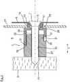
- FIG. 1 is greatly enlarged shown a mounting situation in which a built-in household appliance, such as a dishwasher, is inserted into a niche.
- a built-in household appliance such as a dishwasher
- the sides of the built-in household appliance in a device side direction x are screwed by means of fastening screws 1 to each laterally adjacent furniture side walls 3, of which in the Fig. 1 only one furniture side wall 3 is shown.
- the built-in household appliance Prior to screwing the built-in household appliance is initially positioned in the correct position between the two furniture side walls 3, whereby each left and right side gaps 5 arise, which are bridged by a spacer sleeve 7.
- the built-in household appliance in the device side direction x double arrow
- the built-in household appliance in the device side direction x can be centered between the two furniture side walls 3 of the installation niche.
- the in the Fig. 1 shown spacer sleeve 7 is supported between the furniture side wall 3 and an outer side of the Nutzraumwand 9 of the built-in household appliance.
- the fastening screw 1 is guided, which is screwed with its screw tip 11 in the furniture side wall 3.
- the fastening screw 1 is also guided by a formed in a feeder 15 mounting opening 17 of the Nutzraumwand 9. Accordingly, the trained in the present embodiment as a countersunk head screw head 13 of the mounting screw 1 with the interposition of the passage 15 of the useful space wall 9 in a corresponding recess 19 of the spacer sleeve 7 is supported.
- the fastening screw 1 can therefore be mounted or dismounted starting from the inside of the useful space container.
- a circumferential support frame which is provided for stiffening the usable space container, not shown here.
- the peripheral support frame 21 is arranged in the region of the front-side charging opening of the work space container.
- a passage opening 23 is provided, through which the spacer sleeve 7 is guided to the outside of the Nutzraumwand 9.
- the spacer sleeve 7 made of plastic in the present embodiment is formed adjustable in length, whereby an adaptation to different gap widths between the built-in household appliance and the furniture side wall 3 is made possible.
- the spacer sleeve 7 two telescopically displaceable sleeve parts 25, 27 on.
- the first sleeve part 25 is doing with his in the Fig. 1 shown left end side supported directly on the Nutzraumwand 9.
- the first sleeve part 25 On its side facing away from the useful space wall 9, the first sleeve part 25 has a guide section 29 into which a guide cylinder 31 of the second sleeve part 27 protrudes.
- the inner diameter of the guide section 29 and the outer diameter of the guide cylinder 31 of the second sleeve part 27 are matched to one another such that a longitudinal adjustment of the second sleeve part 27 in the direction of an axis I is made possible.
- the second sleeve member 27 has a through hole 33, which is reduced in comparison to the screw diameter of the fastening screw 1.
- the fastening screw 1 automatically cuts an internal thread in the through hole 33 of the second sleeve part 27.
- the second sleeve part 27 also has a circumferential annular shoulder 35 which faces an end face 37 of the first sleeve part 25 in the axial direction.
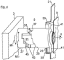
- the peripheral frame 21 In the region of its passage opening 23 parked latching tabs 39, which can be engaged in the manner of a bayonet connection of laterally projecting wings 41 of the first sleeve member 25.
- the spacer sleeve 7 can be centered with respect to the mounting opening 17 in the Nutzraumwand 9. According to the Fig. 2 the spacer sleeve 7 is still spaced over a free distance from the furniture side wall 3.
- the fastening screw 1 is shown partially inserted in the spacer sleeve 7.
- the screw tip 11 abuts in the direction of the axial axis I against the front-side opening edge region 32 of the through hole 33 of the second sleeve part 27.
- the reduced diameter opening edge region 32 thus functions as a driver section, by means of which the fastening screw 1 pushes the second sleeve part 27 in the direction of the axis I moved up in contact with the furniture side wall 3.
- the annular shoulder 35 of the second sleeve part 27 and the facing end face 37 of the first sleeve part 25 extend helically in the circumferential direction relative to each other.
- Both the annular shoulder 35 and the end face 37 are step-shaped with radial surfaces 43 lying in a radial plane and with axial surfaces 45 lying in an axial plane.
- the respective axial surface 45 is in particular a circumferentially extending step surface when looking at the outer circumferential surface of the respective sleeve part.
- the respective radial surface 43 is preferably transverse to the respective adjacent, ie adjacent axial surface 45, in particular perpendicular. It extends in view of the outer circumferential surface of the respective sleeve part preferably substantially parallel to the axial direction I.
- the respective radial surface 43 results in each case by a free cut through the approximately circular cylindrical lateral surface of the respective sleeve part 25, 27 of the spacer sleeve 7 in the radial direction and thus lies essentially parallel to this. It is preferably spanned in a first approximation by the axial direction I and by the radial direction or radial axis of the two circular-cylindrical sleeve parts 25, 27 of the spacer sleeve 7. At its circumferential location on the lateral surface of the respective sleeve part, a tangent formed there forms its surface normal.
- the radial surfaces 43 of at least one sleeve part, such as 25, may also be inclined relative to the axial direction.
- they may each have a positive slope starting from the end of the sleeve part, such as 25, facing the other sleeve part, such as 27 for example.
- the radial surfaces 43 and the axial surfaces 45 alternate successively and thus form a step structure.
- the radial and axial surfaces 43, 45 of the first and second sleeve parts 25, 27 spaced from each other in the direction of the axis I.
Landscapes
- Engineering & Computer Science (AREA)
- General Engineering & Computer Science (AREA)
- Mechanical Engineering (AREA)
- Textile Engineering (AREA)
- Chemical & Material Sciences (AREA)
- Combustion & Propulsion (AREA)
- Assembled Shelves (AREA)
- Pivots And Pivotal Connections (AREA)
- Furniture Connections (AREA)
- Washing And Drying Of Tableware (AREA)
Priority Applications (1)
| Application Number | Priority Date | Filing Date | Title |
|---|---|---|---|
| PL12150639T PL2481335T3 (pl) | 2011-01-31 | 2012-01-10 | Urządzenie gospodarstwa domowego do zabudowy, zwłaszcza zmywarka do naczyń |
Applications Claiming Priority (2)
| Application Number | Priority Date | Filing Date | Title |
|---|---|---|---|
| DE102011003412 | 2011-01-31 | ||
| DE102011003541A DE102011003541A1 (de) | 2011-01-31 | 2011-02-02 | Einbau-Haushaltsgerät, insbesondere Geschirrspülmaschine |
Publications (3)
| Publication Number | Publication Date |
|---|---|
| EP2481335A2 EP2481335A2 (de) | 2012-08-01 |
| EP2481335A3 EP2481335A3 (de) | 2017-12-27 |
| EP2481335B1 true EP2481335B1 (de) | 2019-08-07 |
Family
ID=45497840
Family Applications (1)
| Application Number | Title | Priority Date | Filing Date |
|---|---|---|---|
| EP12150639.8A Active EP2481335B1 (de) | 2011-01-31 | 2012-01-10 | Einbau-Haushaltsgerät, insbesondere Geschirrspülmaschine |
Country Status (4)
| Country | Link |
|---|---|
| US (1) | US8439456B2 (pl) |
| EP (1) | EP2481335B1 (pl) |
| DE (1) | DE102011003541A1 (pl) |
| PL (1) | PL2481335T3 (pl) |
Families Citing this family (16)
| Publication number | Priority date | Publication date | Assignee | Title |
|---|---|---|---|---|
| US10563337B2 (en) * | 2012-12-07 | 2020-02-18 | Dongbu Daewoo Electronics Corporation | Wall-mounted drum washing machine |
| EP2979604B1 (en) * | 2014-07-31 | 2018-05-09 | Whirlpool EMEA S.p.A | Integrated dishwasher |
| DE102015207568B4 (de) | 2015-04-24 | 2020-01-16 | BSH Hausgeräte GmbH | Befestigungsvorrichtung zum Befestigen eines Haushaltsgeräts an einer Wand und Haushaltsgerät |
| US10286433B2 (en) * | 2016-02-27 | 2019-05-14 | Steel King Industries, Inc. | Shimless spacer |
| WO2018001497A1 (en) * | 2016-06-30 | 2018-01-04 | Electrolux Appliances Aktiebolag | Dishwasher |
| US10337543B2 (en) * | 2017-04-04 | 2019-07-02 | Multimaterial-Welding Ag | Securing a second object to a first object |
| DE102019110201A1 (de) * | 2019-04-17 | 2020-10-22 | Witte Automotive Gmbh | Toleranzausgleichsvorrichtung |
| EP3825783B1 (fr) * | 2019-11-25 | 2025-05-07 | ETA SA Manufacture Horlogère Suisse | Mécanisme de réglage d'un pont d horlogerie |
| KR20220011903A (ko) | 2020-07-22 | 2022-02-03 | 삼성전자주식회사 | 식기 세척기 |
| KR102385283B1 (ko) * | 2021-07-19 | 2022-04-08 | 강재성 | 공차 보정 시스템 |
| KR102385284B1 (ko) * | 2021-08-20 | 2022-04-08 | 강재성 | 공차 보정 시스템 |
| CN113615998B (zh) * | 2021-09-08 | 2024-12-31 | 浙江亿田智能厨电股份有限公司 | 一种橱柜与集成灶组合的台板前装饰板快速连接结构 |
| US11771300B2 (en) * | 2021-10-18 | 2023-10-03 | Haier Us Appliance Solutions, Inc. | Universal bracket for supporting racks in a dishwasher appliance |
| CN116115151B (zh) * | 2022-11-07 | 2025-08-05 | 陕西康佳智能家电有限公司 | 一种嵌入式洗碗机与橱柜的装配结构 |
| TR2023009686A1 (tr) * | 2023-08-11 | 2025-02-21 | Vestel Beyaz Esya Sanayi Ve Ticaret Anonim Sirketi | Ankastre ev gereçleri için bir bağlantı sistemi. |
| US20250059991A1 (en) * | 2023-08-17 | 2025-02-20 | Hanwit Precision Industries Ltd. | Board assembly device |
Family Cites Families (29)
| Publication number | Priority date | Publication date | Assignee | Title |
|---|---|---|---|---|
| DE7534416U (de) | 1975-10-30 | 1976-08-05 | Bosch-Siemens Hausgeraete Gmbh, 7000 Stuttgart | Vorrichtung zum befestigen eines einbaugeraetes in einem gehaeuse |
| US4359250A (en) * | 1980-11-03 | 1982-11-16 | General Electric Company | Dishwasher tub and frame assembly |
| US4693526A (en) * | 1982-01-04 | 1987-09-15 | Whirlpool Corporation | Appliance support |
| US4453346A (en) * | 1982-05-24 | 1984-06-12 | United States Gypsum Company | Adjustable wall jamb for shower door |
| US4940298A (en) * | 1989-06-19 | 1990-07-10 | White Consolidated Industries, Inc. | Plastic dishwasher tub and support structure |
| AT398906B (de) * | 1990-04-12 | 1995-02-27 | Tyrolia Freizeitgeraete | Stossdämpfer zur befestigung von skibindungen |
| US5288191A (en) * | 1991-08-26 | 1994-02-22 | Ewald Witte Gmbh & Co. Kg | Device for the clamping attachment of spaced structural parts |
| DE59106601D1 (de) * | 1991-11-22 | 1995-11-02 | Werner Simon | Schraubeinheit. |
| JP2864925B2 (ja) * | 1992-12-28 | 1999-03-08 | 日産自動車株式会社 | ステアリングメンバの取付構造 |
| US5758676A (en) * | 1996-08-06 | 1998-06-02 | White Consolidated Industries, Inc. | Support-door hinge |
| DE19642446C2 (de) * | 1996-10-15 | 2000-06-15 | Ewald Witte Gmbh & Co Kg | Vorrichtung zum Halten zweier Bauteile in einer Abstandslage zueinander |
| US5906450A (en) * | 1997-06-27 | 1999-05-25 | Ng; Gim Shek | Short in-line turnbuckle |
| JP4331821B2 (ja) * | 1998-05-04 | 2009-09-16 | シュヴァルツビッヒ イェルク | 構造部品を相互連結するための装置および方法 |
| US6357953B1 (en) * | 1999-12-16 | 2002-03-19 | General Motors Corporation | Tolerance compensation apparatus |
| WO2002010597A1 (en) * | 2000-07-28 | 2002-02-07 | Ozawa, Junzo | Fastening implement |
| ES2210065T3 (es) * | 2000-08-11 | 2004-07-01 | Jorg Schwarzbich | Dispositivo para unir piezas constructivas. |
| DE20021194U1 (de) * | 2000-12-14 | 2002-04-18 | Schwarzbich, Jörg, 33615 Bielefeld | Vorrichtung zum Verbinden von Bauteilen |
| US6884014B2 (en) * | 2001-04-23 | 2005-04-26 | The Gates Corporation | Tolerance compensating mounting device |
| JP4028968B2 (ja) * | 2001-05-23 | 2008-01-09 | 本田技研工業株式会社 | 車両のプレート取付構造。 |
| CN1547640A (zh) * | 2001-08-30 | 2004-11-17 | 用于固定连杆和/或滑轨的夹紧器,此连杆和/或滑轨具有在其上导向的滑移部件 | |
| DE10151383A1 (de) * | 2001-10-18 | 2003-04-30 | Boellhoff Gmbh | Toleranzausgleichsanordnung |
| DE10163182A1 (de) * | 2001-12-21 | 2003-07-03 | Bsh Bosch Siemens Hausgeraete | Befestigungselement zum Befestigen eines Haushaltgeräts |
| US20030230955A1 (en) * | 2002-06-12 | 2003-12-18 | Welch Rodney M. | Dishwasher trim strip |
| US7488135B2 (en) * | 2003-07-29 | 2009-02-10 | Aoyama Seisakusho Co., Ltd. | Fastening device |
| US7794340B2 (en) * | 2006-01-23 | 2010-09-14 | Quickswing, Inc. | Adjustable length training bat |
| US20070207012A1 (en) * | 2006-03-06 | 2007-09-06 | Nissan Technical Center North America, Inc. | Tolerance compensating mounting device |
| DE202006012493U1 (de) * | 2006-08-14 | 2006-11-02 | Böllhoff Verbindungstechnik GmbH | Befestigungseinrichtung mit Toleranzausgleich |
| US7987637B2 (en) * | 2006-09-25 | 2011-08-02 | Smith Patrick J | Adjustable shim |
| FR2919258A1 (fr) * | 2007-07-25 | 2009-01-30 | Faurecia Interieur Ind Snc | Sous-ensemble de vehicule automobile. |
-
2011
- 2011-02-02 DE DE102011003541A patent/DE102011003541A1/de not_active Withdrawn
- 2011-02-04 US US13/021,006 patent/US8439456B2/en active Active
-
2012
- 2012-01-10 PL PL12150639T patent/PL2481335T3/pl unknown
- 2012-01-10 EP EP12150639.8A patent/EP2481335B1/de active Active
Non-Patent Citations (1)
| Title |
|---|
| None * |
Also Published As
| Publication number | Publication date |
|---|---|
| EP2481335A3 (de) | 2017-12-27 |
| EP2481335A2 (de) | 2012-08-01 |
| US20120194047A1 (en) | 2012-08-02 |
| US8439456B2 (en) | 2013-05-14 |
| PL2481335T3 (pl) | 2020-01-31 |
| DE102011003541A1 (de) | 2012-08-02 |
Similar Documents
| Publication | Publication Date | Title |
|---|---|---|
| EP2481335B1 (de) | Einbau-Haushaltsgerät, insbesondere Geschirrspülmaschine | |
| EP2495453B1 (de) | Befestigungseinrichtung mit Toleranzausgleich | |
| DE102010051372B4 (de) | Verbindungselement mit integrierter Schnappverbindung | |
| EP1961976B1 (de) | Befestigungseinheit | |
| EP3209888B1 (de) | Schnellbefestiger, verfahren zur verbindung von zwei bauteilen mittels des schnellbefestigers und herstellungsverfahren dafür | |
| EP1744063A2 (de) | Toleranzausgleichsanordnung aus Kunststoff | |
| EP0458069A1 (de) | Querverbindung von Profilstäben | |
| AT516984B1 (de) | Vorrichtung zur Montage eines Möbelbeschlages | |
| DE102019113663B4 (de) | Abstandhalter für eine befestigungsanordnung, befestigungsanordnung mit einem solchen abstandhalter sowie verfahren zum befestigen eines montageteils an einem trägerteil | |
| EP2742199B1 (de) | Befestigungsanordnung zur befestigung eines bauteils an einer nut eines fensters, einer tür oder dergleichen | |
| EP2466025A2 (de) | Dämmstoffhalter | |
| EP1297265B1 (de) | Vorrichtung zur befestigung eines ersten bauteiles in einer abstandslage zu einem zweiten bauteil | |
| EP3101188B1 (de) | Dämmstoffhalter zur befestigung von dämmstoffplatten an einen untergrund | |
| DE102014113126A1 (de) | Toleranzausgleichsvorrichtung | |
| DE202009013488U1 (de) | Vorrichtung zum Fixieren eines Baukörpers in einer Gebäudeöffnung | |
| EP1191175A2 (de) | Befestigungsanordnung für einen Beschlagsteil | |
| EP1713991B1 (de) | Türdrückerpaar mit Türdrückerklemmbefestigung | |
| DE102011004315A1 (de) | Vorrichtung zum Einbau einer Geschirrspülmaschine in eine Einbaunische | |
| EP3736464A1 (de) | Abstandhalter für eine befestigungsanordnung, befestigungsanordnung mit einem solchen abstandhalter sowie verfahren zum befestigen eines montageteils an einem trägerteil | |
| EP1477626A2 (de) | Schloss mit längeneinstellbarer Falle | |
| EP2682543A2 (de) | Beschlaganordnung | |
| DE102011055363A1 (de) | Toleranzausgleichsverschraubung | |
| DE102010055808A1 (de) | Befestigungsvorrichtung | |
| DE3725719C2 (de) | Verfahren und Vorrichtung zur Befestigung eines Griffes, oder dergleichen | |
| EP2764189B1 (de) | Federaufnahmekonus für eine torsionsfeder mit einem nach innen oder aussen abgebogenen drehmomentübertragungsschenkel |
Legal Events
| Date | Code | Title | Description |
|---|---|---|---|
| PUAI | Public reference made under article 153(3) epc to a published international application that has entered the european phase |
Free format text: ORIGINAL CODE: 0009012 |
|
| AK | Designated contracting states |
Kind code of ref document: A2 Designated state(s): AL AT BE BG CH CY CZ DE DK EE ES FI FR GB GR HR HU IE IS IT LI LT LU LV MC MK MT NL NO PL PT RO RS SE SI SK SM TR |
|
| AX | Request for extension of the european patent |
Extension state: BA ME |
|
| RAP1 | Party data changed (applicant data changed or rights of an application transferred) |
Owner name: BSH HAUSGERAETE GMBH |
|
| PUAL | Search report despatched |
Free format text: ORIGINAL CODE: 0009013 |
|
| AK | Designated contracting states |
Kind code of ref document: A3 Designated state(s): AL AT BE BG CH CY CZ DE DK EE ES FI FR GB GR HR HU IE IS IT LI LT LU LV MC MK MT NL NO PL PT RO RS SE SI SK SM TR |
|
| AX | Request for extension of the european patent |
Extension state: BA ME |
|
| RIC1 | Information provided on ipc code assigned before grant |
Ipc: D06F 39/00 20060101ALI20171123BHEP Ipc: A47L 15/42 20060101AFI20171123BHEP Ipc: F24C 15/08 20060101ALI20171123BHEP Ipc: D06F 39/12 20060101ALI20171123BHEP Ipc: D06F 58/20 20060101ALI20171123BHEP |
|
| STAA | Information on the status of an ep patent application or granted ep patent |
Free format text: STATUS: REQUEST FOR EXAMINATION WAS MADE |
|
| 17P | Request for examination filed |
Effective date: 20180627 |
|
| RBV | Designated contracting states (corrected) |
Designated state(s): AL AT BE BG CH CY CZ DE DK EE ES FI FR GB GR HR HU IE IS IT LI LT LU LV MC MK MT NL NO PL PT RO RS SE SI SK SM TR |
|
| GRAP | Despatch of communication of intention to grant a patent |
Free format text: ORIGINAL CODE: EPIDOSNIGR1 |
|
| STAA | Information on the status of an ep patent application or granted ep patent |
Free format text: STATUS: GRANT OF PATENT IS INTENDED |
|
| INTG | Intention to grant announced |
Effective date: 20190227 |
|
| GRAS | Grant fee paid |
Free format text: ORIGINAL CODE: EPIDOSNIGR3 |
|
| GRAA | (expected) grant |
Free format text: ORIGINAL CODE: 0009210 |
|
| STAA | Information on the status of an ep patent application or granted ep patent |
Free format text: STATUS: THE PATENT HAS BEEN GRANTED |
|
| AK | Designated contracting states |
Kind code of ref document: B1 Designated state(s): AL AT BE BG CH CY CZ DE DK EE ES FI FR GB GR HR HU IE IS IT LI LT LU LV MC MK MT NL NO PL PT RO RS SE SI SK SM TR |
|
| REG | Reference to a national code |
Ref country code: GB Ref legal event code: FG4D Free format text: NOT ENGLISH |
|
| REG | Reference to a national code |
Ref country code: CH Ref legal event code: EP Ref country code: AT Ref legal event code: REF Ref document number: 1162560 Country of ref document: AT Kind code of ref document: T Effective date: 20190815 |
|
| REG | Reference to a national code |
Ref country code: DE Ref legal event code: R096 Ref document number: 502012015105 Country of ref document: DE |
|
| REG | Reference to a national code |
Ref country code: IE Ref legal event code: FG4D Free format text: LANGUAGE OF EP DOCUMENT: GERMAN |
|
| REG | Reference to a national code |
Ref country code: NL Ref legal event code: MP Effective date: 20190807 |
|
| REG | Reference to a national code |
Ref country code: LT Ref legal event code: MG4D |
|
| PG25 | Lapsed in a contracting state [announced via postgrant information from national office to epo] |
Ref country code: BG Free format text: LAPSE BECAUSE OF FAILURE TO SUBMIT A TRANSLATION OF THE DESCRIPTION OR TO PAY THE FEE WITHIN THE PRESCRIBED TIME-LIMIT Effective date: 20191107 Ref country code: SE Free format text: LAPSE BECAUSE OF FAILURE TO SUBMIT A TRANSLATION OF THE DESCRIPTION OR TO PAY THE FEE WITHIN THE PRESCRIBED TIME-LIMIT Effective date: 20190807 Ref country code: NL Free format text: LAPSE BECAUSE OF FAILURE TO SUBMIT A TRANSLATION OF THE DESCRIPTION OR TO PAY THE FEE WITHIN THE PRESCRIBED TIME-LIMIT Effective date: 20190807 Ref country code: PT Free format text: LAPSE BECAUSE OF FAILURE TO SUBMIT A TRANSLATION OF THE DESCRIPTION OR TO PAY THE FEE WITHIN THE PRESCRIBED TIME-LIMIT Effective date: 20191209 Ref country code: LT Free format text: LAPSE BECAUSE OF FAILURE TO SUBMIT A TRANSLATION OF THE DESCRIPTION OR TO PAY THE FEE WITHIN THE PRESCRIBED TIME-LIMIT Effective date: 20190807 Ref country code: HR Free format text: LAPSE BECAUSE OF FAILURE TO SUBMIT A TRANSLATION OF THE DESCRIPTION OR TO PAY THE FEE WITHIN THE PRESCRIBED TIME-LIMIT Effective date: 20190807 Ref country code: FI Free format text: LAPSE BECAUSE OF FAILURE TO SUBMIT A TRANSLATION OF THE DESCRIPTION OR TO PAY THE FEE WITHIN THE PRESCRIBED TIME-LIMIT Effective date: 20190807 Ref country code: NO Free format text: LAPSE BECAUSE OF FAILURE TO SUBMIT A TRANSLATION OF THE DESCRIPTION OR TO PAY THE FEE WITHIN THE PRESCRIBED TIME-LIMIT Effective date: 20191107 |
|
| PG25 | Lapsed in a contracting state [announced via postgrant information from national office to epo] |
Ref country code: LV Free format text: LAPSE BECAUSE OF FAILURE TO SUBMIT A TRANSLATION OF THE DESCRIPTION OR TO PAY THE FEE WITHIN THE PRESCRIBED TIME-LIMIT Effective date: 20190807 Ref country code: ES Free format text: LAPSE BECAUSE OF FAILURE TO SUBMIT A TRANSLATION OF THE DESCRIPTION OR TO PAY THE FEE WITHIN THE PRESCRIBED TIME-LIMIT Effective date: 20190807 Ref country code: GR Free format text: LAPSE BECAUSE OF FAILURE TO SUBMIT A TRANSLATION OF THE DESCRIPTION OR TO PAY THE FEE WITHIN THE PRESCRIBED TIME-LIMIT Effective date: 20191108 Ref country code: IS Free format text: LAPSE BECAUSE OF FAILURE TO SUBMIT A TRANSLATION OF THE DESCRIPTION OR TO PAY THE FEE WITHIN THE PRESCRIBED TIME-LIMIT Effective date: 20191207 Ref country code: RS Free format text: LAPSE BECAUSE OF FAILURE TO SUBMIT A TRANSLATION OF THE DESCRIPTION OR TO PAY THE FEE WITHIN THE PRESCRIBED TIME-LIMIT Effective date: 20190807 Ref country code: AL Free format text: LAPSE BECAUSE OF FAILURE TO SUBMIT A TRANSLATION OF THE DESCRIPTION OR TO PAY THE FEE WITHIN THE PRESCRIBED TIME-LIMIT Effective date: 20190807 |
|
| PG25 | Lapsed in a contracting state [announced via postgrant information from national office to epo] |
Ref country code: DK Free format text: LAPSE BECAUSE OF FAILURE TO SUBMIT A TRANSLATION OF THE DESCRIPTION OR TO PAY THE FEE WITHIN THE PRESCRIBED TIME-LIMIT Effective date: 20190807 Ref country code: RO Free format text: LAPSE BECAUSE OF FAILURE TO SUBMIT A TRANSLATION OF THE DESCRIPTION OR TO PAY THE FEE WITHIN THE PRESCRIBED TIME-LIMIT Effective date: 20190807 Ref country code: IT Free format text: LAPSE BECAUSE OF FAILURE TO SUBMIT A TRANSLATION OF THE DESCRIPTION OR TO PAY THE FEE WITHIN THE PRESCRIBED TIME-LIMIT Effective date: 20190807 Ref country code: EE Free format text: LAPSE BECAUSE OF FAILURE TO SUBMIT A TRANSLATION OF THE DESCRIPTION OR TO PAY THE FEE WITHIN THE PRESCRIBED TIME-LIMIT Effective date: 20190807 |
|
| PG25 | Lapsed in a contracting state [announced via postgrant information from national office to epo] |
Ref country code: SK Free format text: LAPSE BECAUSE OF FAILURE TO SUBMIT A TRANSLATION OF THE DESCRIPTION OR TO PAY THE FEE WITHIN THE PRESCRIBED TIME-LIMIT Effective date: 20190807 Ref country code: SM Free format text: LAPSE BECAUSE OF FAILURE TO SUBMIT A TRANSLATION OF THE DESCRIPTION OR TO PAY THE FEE WITHIN THE PRESCRIBED TIME-LIMIT Effective date: 20190807 Ref country code: IS Free format text: LAPSE BECAUSE OF FAILURE TO SUBMIT A TRANSLATION OF THE DESCRIPTION OR TO PAY THE FEE WITHIN THE PRESCRIBED TIME-LIMIT Effective date: 20200224 Ref country code: CZ Free format text: LAPSE BECAUSE OF FAILURE TO SUBMIT A TRANSLATION OF THE DESCRIPTION OR TO PAY THE FEE WITHIN THE PRESCRIBED TIME-LIMIT Effective date: 20190807 |
|
| REG | Reference to a national code |
Ref country code: DE Ref legal event code: R097 Ref document number: 502012015105 Country of ref document: DE |
|
| PLBE | No opposition filed within time limit |
Free format text: ORIGINAL CODE: 0009261 |
|
| STAA | Information on the status of an ep patent application or granted ep patent |
Free format text: STATUS: NO OPPOSITION FILED WITHIN TIME LIMIT |
|
| PG2D | Information on lapse in contracting state deleted |
Ref country code: IS |
|
| 26N | No opposition filed |
Effective date: 20200603 |
|
| PG25 | Lapsed in a contracting state [announced via postgrant information from national office to epo] |
Ref country code: SI Free format text: LAPSE BECAUSE OF FAILURE TO SUBMIT A TRANSLATION OF THE DESCRIPTION OR TO PAY THE FEE WITHIN THE PRESCRIBED TIME-LIMIT Effective date: 20190807 Ref country code: MC Free format text: LAPSE BECAUSE OF FAILURE TO SUBMIT A TRANSLATION OF THE DESCRIPTION OR TO PAY THE FEE WITHIN THE PRESCRIBED TIME-LIMIT Effective date: 20190807 |
|
| REG | Reference to a national code |
Ref country code: CH Ref legal event code: PL |
|
| GBPC | Gb: european patent ceased through non-payment of renewal fee |
Effective date: 20200110 |
|
| REG | Reference to a national code |
Ref country code: BE Ref legal event code: MM Effective date: 20200131 |
|
| PG25 | Lapsed in a contracting state [announced via postgrant information from national office to epo] |
Ref country code: LU Free format text: LAPSE BECAUSE OF NON-PAYMENT OF DUE FEES Effective date: 20200110 Ref country code: FR Free format text: LAPSE BECAUSE OF NON-PAYMENT OF DUE FEES Effective date: 20200131 Ref country code: GB Free format text: LAPSE BECAUSE OF NON-PAYMENT OF DUE FEES Effective date: 20200110 |
|
| PG25 | Lapsed in a contracting state [announced via postgrant information from national office to epo] |
Ref country code: BE Free format text: LAPSE BECAUSE OF NON-PAYMENT OF DUE FEES Effective date: 20200131 Ref country code: LI Free format text: LAPSE BECAUSE OF NON-PAYMENT OF DUE FEES Effective date: 20200131 Ref country code: CH Free format text: LAPSE BECAUSE OF NON-PAYMENT OF DUE FEES Effective date: 20200131 |
|
| PG25 | Lapsed in a contracting state [announced via postgrant information from national office to epo] |
Ref country code: IE Free format text: LAPSE BECAUSE OF NON-PAYMENT OF DUE FEES Effective date: 20200110 |
|
| REG | Reference to a national code |
Ref country code: AT Ref legal event code: MM01 Ref document number: 1162560 Country of ref document: AT Kind code of ref document: T Effective date: 20200110 |
|
| PG25 | Lapsed in a contracting state [announced via postgrant information from national office to epo] |
Ref country code: AT Free format text: LAPSE BECAUSE OF NON-PAYMENT OF DUE FEES Effective date: 20200110 |
|
| PG25 | Lapsed in a contracting state [announced via postgrant information from national office to epo] |
Ref country code: MT Free format text: LAPSE BECAUSE OF FAILURE TO SUBMIT A TRANSLATION OF THE DESCRIPTION OR TO PAY THE FEE WITHIN THE PRESCRIBED TIME-LIMIT Effective date: 20190807 Ref country code: CY Free format text: LAPSE BECAUSE OF FAILURE TO SUBMIT A TRANSLATION OF THE DESCRIPTION OR TO PAY THE FEE WITHIN THE PRESCRIBED TIME-LIMIT Effective date: 20190807 |
|
| PG25 | Lapsed in a contracting state [announced via postgrant information from national office to epo] |
Ref country code: MK Free format text: LAPSE BECAUSE OF FAILURE TO SUBMIT A TRANSLATION OF THE DESCRIPTION OR TO PAY THE FEE WITHIN THE PRESCRIBED TIME-LIMIT Effective date: 20190807 |
|
| PGFP | Annual fee paid to national office [announced via postgrant information from national office to epo] |
Ref country code: PL Payment date: 20241220 Year of fee payment: 14 |
|
| PGFP | Annual fee paid to national office [announced via postgrant information from national office to epo] |
Ref country code: DE Payment date: 20250131 Year of fee payment: 14 |
|
| PGFP | Annual fee paid to national office [announced via postgrant information from national office to epo] |
Ref country code: TR Payment date: 20250107 Year of fee payment: 14 |