EP2481335B1 - Built-in household appliance, in particular dishwasher - Google Patents
Built-in household appliance, in particular dishwasher Download PDFInfo
- Publication number
- EP2481335B1 EP2481335B1 EP12150639.8A EP12150639A EP2481335B1 EP 2481335 B1 EP2481335 B1 EP 2481335B1 EP 12150639 A EP12150639 A EP 12150639A EP 2481335 B1 EP2481335 B1 EP 2481335B1
- Authority
- EP
- European Patent Office
- Prior art keywords
- built
- sleeve part
- sleeve
- household appliance
- wall
- Prior art date
- Legal status (The legal status is an assumption and is not a legal conclusion. Google has not performed a legal analysis and makes no representation as to the accuracy of the status listed.)
- Active
Links
- 238000009434 installation Methods 0.000 claims description 12
- 230000033001 locomotion Effects 0.000 claims description 11
- 230000002093 peripheral effect Effects 0.000 claims description 5
- 230000007704 transition Effects 0.000 claims description 3
- 230000000717 retained effect Effects 0.000 claims 1
- 125000006850 spacer group Chemical group 0.000 description 36
- 238000003780 insertion Methods 0.000 description 4
- 230000037431 insertion Effects 0.000 description 4
- 238000000034 method Methods 0.000 description 3
- 230000008569 process Effects 0.000 description 3
- 230000009471 action Effects 0.000 description 2
- 238000011161 development Methods 0.000 description 2
- 230000018109 developmental process Effects 0.000 description 2
- 230000000694 effects Effects 0.000 description 2
- 239000002023 wood Substances 0.000 description 2
- 230000006978 adaptation Effects 0.000 description 1
- 238000010276 construction Methods 0.000 description 1
- 230000001419 dependent effect Effects 0.000 description 1
- 238000005516 engineering process Methods 0.000 description 1
- 230000002349 favourable effect Effects 0.000 description 1
- 230000000149 penetrating effect Effects 0.000 description 1
- 230000001360 synchronised effect Effects 0.000 description 1
Images

Classifications
-
- A—HUMAN NECESSITIES
- A47—FURNITURE; DOMESTIC ARTICLES OR APPLIANCES; COFFEE MILLS; SPICE MILLS; SUCTION CLEANERS IN GENERAL
- A47L—DOMESTIC WASHING OR CLEANING; SUCTION CLEANERS IN GENERAL
- A47L15/00—Washing or rinsing machines for crockery or tableware
- A47L15/42—Details
- A47L15/4251—Details of the casing
- A47L15/427—Arrangements for setting the machine, e.g. anti-tip devices therefor, fixing of integrated machines
-
- D—TEXTILES; PAPER
- D06—TREATMENT OF TEXTILES OR THE LIKE; LAUNDERING; FLEXIBLE MATERIALS NOT OTHERWISE PROVIDED FOR
- D06F—LAUNDERING, DRYING, IRONING, PRESSING OR FOLDING TEXTILE ARTICLES
- D06F39/00—Details of washing machines not specific to a single type of machines covered by groups D06F9/00 - D06F27/00
- D06F39/001—Arrangements for transporting, moving, or setting washing machines; Protective arrangements for use during transport
-
- F—MECHANICAL ENGINEERING; LIGHTING; HEATING; WEAPONS; BLASTING
- F16—ENGINEERING ELEMENTS AND UNITS; GENERAL MEASURES FOR PRODUCING AND MAINTAINING EFFECTIVE FUNCTIONING OF MACHINES OR INSTALLATIONS; THERMAL INSULATION IN GENERAL
- F16B—DEVICES FOR FASTENING OR SECURING CONSTRUCTIONAL ELEMENTS OR MACHINE PARTS TOGETHER, e.g. NAILS, BOLTS, CIRCLIPS, CLAMPS, CLIPS OR WEDGES; JOINTS OR JOINTING
- F16B5/00—Joining sheets or plates, e.g. panels, to one another or to strips or bars parallel to them
- F16B5/02—Joining sheets or plates, e.g. panels, to one another or to strips or bars parallel to them by means of fastening members using screw-thread
- F16B5/0216—Joining sheets or plates, e.g. panels, to one another or to strips or bars parallel to them by means of fastening members using screw-thread the position of the plates to be connected being adjustable
- F16B5/0233—Joining sheets or plates, e.g. panels, to one another or to strips or bars parallel to them by means of fastening members using screw-thread the position of the plates to be connected being adjustable allowing for adjustment perpendicular to the plane of the plates
-
- F—MECHANICAL ENGINEERING; LIGHTING; HEATING; WEAPONS; BLASTING
- F24—HEATING; RANGES; VENTILATING
- F24C—DOMESTIC STOVES OR RANGES ; DETAILS OF DOMESTIC STOVES OR RANGES, OF GENERAL APPLICATION
- F24C15/00—Details
- F24C15/08—Foundations or supports plates; Legs or pillars; Casings; Wheels
- F24C15/083—Anti-tip arrangements
-
- A—HUMAN NECESSITIES
- A47—FURNITURE; DOMESTIC ARTICLES OR APPLIANCES; COFFEE MILLS; SPICE MILLS; SUCTION CLEANERS IN GENERAL
- A47B—TABLES; DESKS; OFFICE FURNITURE; CABINETS; DRAWERS; GENERAL DETAILS OF FURNITURE
- A47B77/00—Kitchen cabinets
- A47B77/04—Provision for particular uses of compartments or other parts ; Compartments moving up and down, revolving parts
- A47B77/08—Provision for particular uses of compartments or other parts ; Compartments moving up and down, revolving parts for incorporating apparatus operated by power, including water power; for incorporating apparatus for cooking, cooling, or laundry purposes
-
- F—MECHANICAL ENGINEERING; LIGHTING; HEATING; WEAPONS; BLASTING
- F16—ENGINEERING ELEMENTS AND UNITS; GENERAL MEASURES FOR PRODUCING AND MAINTAINING EFFECTIVE FUNCTIONING OF MACHINES OR INSTALLATIONS; THERMAL INSULATION IN GENERAL
- F16B—DEVICES FOR FASTENING OR SECURING CONSTRUCTIONAL ELEMENTS OR MACHINE PARTS TOGETHER, e.g. NAILS, BOLTS, CIRCLIPS, CLAMPS, CLIPS OR WEDGES; JOINTS OR JOINTING
- F16B43/00—Washers or equivalent devices; Other devices for supporting bolt-heads or nuts
- F16B43/009—Washers or equivalent devices; Other devices for supporting bolt-heads or nuts with a wedging effect in order to adjust the height of the washer
Landscapes
- Engineering & Computer Science (AREA)
- General Engineering & Computer Science (AREA)
- Mechanical Engineering (AREA)
- Textile Engineering (AREA)
- Chemical & Material Sciences (AREA)
- Combustion & Propulsion (AREA)
- Assembled Shelves (AREA)
- Washing And Drying Of Tableware (AREA)
- Pivots And Pivotal Connections (AREA)
- Furniture Connections (AREA)
Description
Die Erfindung betrifft ein Einbauhaushaltsgerät, insbesondere eine Geschirrspülmaschine, mit mindestens einer längenverstellbaren Abstandshülse zum Befestigen des Einbauhaushaltsgeräts an zumindest einer Wandung, insbesondere einer Möbelwand, mittels einer Befestigungsschraube, wobei die Abstandshülse ein an dem Einbauhaushaltsgerät gelagertes, erstes Hülsenteil und ein teleskopartig dazu verstellbares, zweites Hülsenteil aufweist, welches mit Bezug auf das erste Hülsenteil bis in Anlage mit der Wandung, insbesondere der Möbelwand, entlang einer Achse längenverstellbar ist.The invention relates to a built-in household appliance, in particular a dishwasher, with at least one length-adjustable spacer for attaching the built-in household appliance to at least one wall, in particular a furniture wall, by means of a fastening screw, wherein the spacer sleeve mounted on the Einbauhaushaltsgerät, first sleeve part and a telescopically adjustable second Sleeve part which, with respect to the first sleeve part is adjustable in length along an axis along with the wall, in particular the furniture wall.
Einbauhaushaltsgeräte, wie zum Beispiel Geschirrspülmaschinen, werden nach dem Einsetzen zum Beispiel in Einbaunischen von Küchenmöbeln beispielsweise über Haltebleche oder Haltewinkelelemente an angrenzenden Möbelwänden seitlich verschraubt.Built-in household appliances, such as dishwashers are screwed laterally after insertion, for example, in the niche of kitchen furniture, for example on holding plates or bracket elements on adjacent furniture walls.
Die Druckschrift
Zur Befestigung des Einbauhaushaltsgeräts an der Seitenwand des Anbaumöbels wird zunächst der Schraubenbolzen durch Ansetzen eines Schraubenziehers drehbetätigt, wodurch der Schraubenbolzen in der Geräteseitenrichtung ein- oder ausgefahren wird, bis dessen Stirnseite in Anlage mit der Seitenwand des Anbaumöbels ist. In einem zweiten Arbeitsschritt wird dann die Befestigungsschraube in die Durchgangsbohrung des Schraubenbolzens eingeführt und in die Möbelwand eingeschraubt.To attach the built-in household appliance to the side wall of the Anbaumöbels the bolt is first rotationally actuated by applying a screwdriver, whereby the bolt in the device side direction is retracted or extended until the end face is in contact with the side wall of the Anbaumöbels. In a second step, the fastening screw is then inserted into the through hole of the bolt and screwed into the furniture wall.
Die Druckschrift
Eine Aufgabe der Erfindung besteht darin, ein Einbauhaushaltsgerät mit verbesserter Möglichkeit zur Lagesicherung an mindestens einer Wandung, insbesondere einer Einbaunische, bevorzugt einer Nische eines Einbaumöbels oder eines Möbelstücks, eine zugehörige längenverstellbare Abstandshülse sowie eine Vorrichtung beziehungsweise Anordnung zum Befestigen eines Einbauhaushaltsgeräts an mindestens einer Wandung, insbesondere einer Möbelwand einer Einbaunische bereitzustellen, bei der die Längenverstellung der Abstandshülse zur Überwindung eines zwischen dem Einbauhaushaltsgerät und der jeweiligen Wandung, insbesondere der jeweiligen Möbelwand, vorhandenen Spalts montagetechnisch vereinfacht ist.An object of the invention is a built-in household appliance with improved ability to secure the position of at least one wall, in particular a niche, preferably a niche of a built-in furniture or a piece of furniture, an associated length-adjustable spacer sleeve and a device or arrangement for securing a built-in household appliance to at least one wall, in particular to provide a furniture wall of a niche in which the length adjustment of the spacer sleeve to overcome a gap between the built-in household appliance and the respective wall, in particular the respective furniture wall, existing gap is simplifies assembly technology.
Erfindungsgemäß ist eine Verdrehsicherung vorgesehen, welche eine Drehbewegung des zweiten Hülsenteils in Bezug zu dem ersten Hülsenteil um die Achse begrenzt, wobei die Verdrehsicherung an dem ersten Hülsenteil und an dem zweiten Hülsenteil zueinander korrespondierende Stirnseiten aufweist, welche einander in Axialrichtung zugewandt sind. Somit wird die Montage wesentlich vereinfacht, da durch das Ansetzen einer Befestigungsschraube ein Drehmoment auf das zweite Hülsenteil übertragen wird, diese jedoch durch die Verdrehsicherung begrenzt wird und somit ein Fortsetzen der Montage durch Fortsetzen der Einschraubbewegung der Befestigungsschraube zur endgültigen Fixierung der Abstandshülse fortgesetzt werden kann.According to the invention an anti-rotation device is provided, which limits a rotational movement of the second sleeve part with respect to the first sleeve part about the axis, wherein the rotation on the first sleeve part and on the second sleeve part having mutually corresponding end faces, which face each other in the axial direction. Thus, the assembly is much easier because a torque is transmitted to the second sleeve part by applying a fastening screw, but this is limited by the rotation and thus continuing the assembly by continuing the screwing of the mounting screw for final fixation of the spacer sleeve can be continued.
Das zweite Hülsenteil kann für eine mit Bezug auf das erste Hülsenteil erfolgende Längenverstellung der Abstandshülse zweckmäßigerweise einen Mitnehmerabschnitt aufweisen. Die Befestigungsschraube kann beim Einsetzen in die Abstandshülse gegen diesen Mitnehmerabschnitt anstoßen. Im weiteren Montageverlauf kann daher die Befestigungsschraube über den Mitnehmerabschnitt bewegungsgekoppelt mit dem zweiten Hülsenteil verschoben werden, bis das zweite Hülsenteil in Anlage mit der jeweiligen Wandung der Einbaunische, insbesondere der jeweiligen Möbelwand des Einbaumöbelstücks, gebracht ist. Es erfolgt also eine Längenverstellung des zweiten Hülsenteils automatisch mit dem Einsetzen der Befestigungsschraube in das zweite Hülsenteil, wodurch sich der Montageaufwand beim Befestigen des Einbauhaushaltsgeräts an mindestens einer Wandung, insbesondere beim Einbau des Einbauhaushaltsgeräts in die jeweilige Einbaunische reduziert.The second sleeve part can expediently have a driver section for a length adjustment of the spacer sleeve taking place with respect to the first sleeve part. The fastening screw can abut against the driver section during insertion into the spacer sleeve. In the further course of assembly, therefore, the fastening screw can be moved via the driver portion coupled with the second sleeve member until the second sleeve part is brought into contact with the respective wall of the installation niche, in particular the respective furniture wall of the Einbaumöbelstücks. Thus, there is a length adjustment of the second sleeve part automatically with the insertion of the fastening screw in the second sleeve part, which reduces the assembly effort when attaching the built-in household appliance to at least one wall, in particular when installing the built-in household appliance in the respective installation niche.
Die beiden Hülsenteile der Abstandshülse können zweckmäßigerweise zueinander teleskopartig verstellbar sein, um den zwischen dem Einbauhaushaltsgerät und der Möbelwand befindlichen Spalt zu überbrücken. In diesem Fall können die beiden Hülsenteile in Axialrichtung zueinander verschiebbar angeordnet sein. Beispielhaft kann das längsverstellbare Hülsenteil innerhalb des vorzugsweise ortsfest an dem Einbauhaushaltsgerät gehalterten ersten Hülsenteils teleskopartig verschiebbar aufgenommen sein. Der Mitnehmerabschnitt kann dabei an einer Stirnseite des zweiten Hülsenteils ausgebildet sein. Die Befestigungsschraube kann daher beim Einsetzen in die Abstandshülse mit ihrer Schraubenspitze gegen die Stirnseite des Hülsenteils anstoßen und somit das zweite Hülsenteil zur Möbelwand verschieben.The two sleeve parts of the spacer sleeve may conveniently be telescopically adjustable to each other in order to bridge the gap between the built-in household appliance and the furniture wall. In this case, the two sleeve parts may be arranged to be displaceable relative to one another in the axial direction. By way of example, the longitudinally adjustable sleeve part can be accommodated in a telescopically displaceable manner within the first sleeve part which is preferably held fixedly on the installation household appliance. The driver portion may be formed on an end face of the second sleeve part. The fastening screw can therefore abut when inserting into the spacer sleeve with its screw tip against the end face of the sleeve part and thus move the second sleeve part to the furniture wall.
Alternativ kann der Mitnehmerabschnitt ein durchmesserreduzierter Abschnitt in einer Durchgangsbohrung des zweiten Hülsenteils sein. Auf diese Weise wird das zweite Hülsenteil zunächst mit der Schraubenspitze der Befestigungsschraube gegen die Möbelwand gedrückt. Anschließend kann die Befestigungsschraube durch den durchmesserreduzierten Abschnitt der Durchgangsbohrung geschraubt werden, und zwar bis in Schraubeingriff mit der Möbelwand. Alternativ dazu kann der Mitnehmerabschnitt die Durchgangsbohrung des zweiten Hülsenteils in Axialrichtung vollständig verschließen. In diesem Fall ist der Mitnehmerabschnitt so auszulegen, dass er beim Ansetzen der Befestigungsschraube durchbrochen werden kann.Alternatively, the cam portion may be a reduced diameter portion in a through hole of the second sleeve member. In this way, the second sleeve part is first pressed with the screw tip of the fastening screw against the furniture wall. Subsequently, the fastening screw can be screwed through the reduced diameter portion of the through hole, until in screw engagement with the furniture wall. Alternatively, the driver portion may completely close the through hole of the second sleeve member in the axial direction. In this case, the driver section should be designed so that it can be broken when attaching the fastening screw.
Die beiden zueinander korrespondierenden Stirnseiten der Hülsenteileverlaufen in einer Weiterbildung der Erfindung mit einer vorgegebenen Steigung helixförmig, insbesondere schraubenlinienabschnittsförmig, in Umfangsrichtung um die beiden Hülsenteile herum. Dabei kann die Stirnseite des zweiten Hülsenteils an einer Ringschulter ausgebildet sein, welche einen Übergang zwischen einem durchmesserkleineren und einem durchmessergrößeren Außenabschnitt des zweiten Hülsenteils bildet. Der durchmesserkleinere Abschnitt des zweiten Hülsenteils kann teleskopartig verschiebbar innerhalb des ersten Hülsenteils angeordnet sein. Die Stirnseite des ersten Hülsenteils kann demgegenüber der Ringschulter zugewandt an dem ersten Hülsenteil ausgebildet sein.The two mutually corresponding end faces of the sleeve parts run in a development of the invention with a predetermined pitch helical, in particular helical section, in the circumferential direction around the two sleeve parts around. In this case, the end face of the second sleeve part may be formed on an annular shoulder, which forms a transition between a smaller diameter and a larger diameter outer portion of the second sleeve part. The smaller diameter portion of the second sleeve portion may be telescopically slidably disposed within the first sleeve portion. In contrast, the end face of the first sleeve part can be designed to face the annular shoulder on the first sleeve part.
Die Wirkungsweise dieser beiden helixförmig, insbesondere schraubenlinienabschnittsförmig, verlaufenden Stirnseiten der Hülsenteile ist nachfolgend erläutert: So erfolgt zunächst eine Längenverstellung des zweiten Hülsenteils in der Axialrichtung der Abstandshülse, wodurch die beiden korrespondierenden Ringflächen auseinander bewegt werden. Mit einer anschließenden Drehbewegung des zweiten Hülsenteils können dann zumindest Abschnitte der beiden helixförmigen Stirnseiten der Hülsenteile miteinander in Kontakt gebracht werden. In diesem Fall können sich die beiden Hülsenteile aufgrund der Keilwirkung zwischen beiden Hülsenteilen aufeinander abstützen. Dabei ist sicherzustellen, dass beim Einschrauben der Befestigungsschraube ein auf das zweite Hülsenteil aufgebrachtes Drehmoment größer ist als ein entgegenwirkendes Reibmoment, welches als Gegenmoment zwischen dem zweiten Hülsenteil und der Möbelseitenwand erzeugt wird.The mode of action of these two helically, in particular helical section, extending end faces of the sleeve parts is explained below: Thus, initially a length adjustment of the second sleeve part in the axial direction of the spacer sleeve, whereby the two corresponding annular surfaces are moved apart. With a subsequent rotational movement of the second sleeve part then at least portions of the two helical end faces of the sleeve parts can be brought into contact with each other. In this case, the two sleeve parts can be supported on each other due to the wedge effect between the two sleeve parts. It should be ensured that when screwing in the fastening screw a torque applied to the second sleeve part is greater than a counteracting friction torque, which is generated as a counter-torque between the second sleeve part and the furniture side wall.
Um dabei ein Abgleiten der zueinander keilförmig gestalteten Stirnseiten der Hülsenteile zu vermeiden, sind diese in beiden Hülsenteilen zweckmäßigerweise jeweils stufenförmig mit in Radialebene liegenden Radialflächen sowie in Axialebene liegenden Axialflächen ausgebildet. Auf diese Weise werden Schrägabschnitte in den Ringflächen vermieden, bei denen die Gefahr einer nachträglichen unbeabsichtigten Drehbewegung besteht.In order to avoid slipping of the mutually wedge-shaped end faces of the sleeve parts, these are expediently in each case sleeve portions in each case step-shaped with lying in the radial plane radial surfaces and lying in the axial plane axial surfaces. In this way, oblique sections are avoided in the annular surfaces, where there is a risk of subsequent unintentional rotation.
Die Abstandshülse kann insbesondere zwischen dem Schraubenkopf der Befestigungsschraube und der Möbelwand eingespannt sein. Hierzu kann der Schraubenkopf der Befestigungsschraube auf der von dem zweiten Hülsenteil abgewandten Seite des ersten Hülsenteils, etwa in einer darin ausgebildeten Einsenkung, abgestützt sein. Bevorzugt kann dabei zwischen dem ersten Hülsenteil der Abstandshülse und dem Schraubenkopf der Befestigungsschraube ein Öffnungsrandbereich einer Montageöffnung einer Wandung, insbesondere Seitenwand, eines Nutzraumbehälters des Einbauhaushaltsgeräts eingespannt sein. In diesem Fall kann somit die Befestigungsschraube, ausgehend von dem Innenraum des Nutzraumbehälters des Einbauhaushaltsgeräts, nach außen in die jeweilige Wandung, insbesondere in die jeweilige Möbelwand, eingeschraubt werden.The spacer sleeve can in particular be clamped between the screw head of the fastening screw and the furniture wall. For this purpose, the screw head of the fastening screw on the side facing away from the second sleeve part side of the first sleeve part, such as in a recess formed therein, be supported. Preferably, between the first sleeve part of the spacer sleeve and the screw head of the fastening screw an opening edge region of a mounting opening of a wall, in particular side wall, of a useful space container of the built-in household appliance can be clamped. In this case, thus, the fastening screw, starting from the interior of the work space container of the built-in household appliance, are screwed outwards into the respective wall, in particular into the respective furniture wall.
Ferner gehört zur Erfindung eine längenverstellbare Abstandshülse zum Befestigen eines Einbauhaushaltsgeräts, insbesondere einer Geschirrspülmaschine, nach Anspruch 12 sowie eine Anordnung zum Befestigen eins Einbauhaushaltsgeräts an mindestens einer Wandung, insbesondere einer Einbaunische, bevorzugt einer Nische eines Einbaumöbels oder Möbelstücks, nach Anspruch 13.Furthermore, the invention relates to a length-adjustable spacer sleeve for fastening a built-in household appliance, in particular a dishwasher, according to claim 12 and an arrangement for attaching a built-in household appliance to at least one wall, in particular an installation niche, preferably a niche of a built-in furniture or piece of furniture, according to
Die vorstehend erläuterten und/oder in den abhängigen Ansprüchen wiedergegebenen vorteilhaften Aus- und Weiterbildungen der Erfindung können dabei - außer zum Beispiel in den Fällen eindeutiger Abhängigkeiten oder unvereinbarer Alternativen - einzeln oder aber auch in beliebiger Kombination miteinander zur Anwendung kommen.The above-explained and / or reproduced in the dependent claims advantageous embodiments and refinements of the invention can - except for example in cases of clear dependencies or incompatible alternatives - individually or in any combination with each other are used.
Die Erfindung und ihre vorteilhaften Aus- und Weiterbildungen sowie deren Vorteile werden nachfolgend anhand von Zeichnungen näher erläutert.The invention and its advantageous embodiments and further developments and advantages thereof are explained in more detail below with reference to drawings.
Es zeigen, jeweils in einer schematischen Prinzipskizze:
- Fig. 1
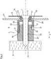
- in einer vergrößerten Seitenschnittdarstellung ein Ausführungsbeispiel einer nach dem erfindungsgemäßen Konstruktionsprinzip ausgebildeten Abstandshülse in einer Einbaulage, in der ein Einbauhaushaltsgerät an der Möbelwand einer Einbaunische befestigt ist; sowie
- Fig. 2 bis 4
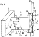
- jeweils unterschiedliche Raumansichten, welche eine Längenverstellung der Abstandshülse von
Fig. 1 bei der Montage des Einbauhaushaltsgeräts in der Einbaunische veranschaulichen.
- Fig. 1
- in an enlarged side sectional view of an embodiment of a trained according to the construction principle of the invention spacer sleeve in an installed position in which a built-in household appliance is attached to the furniture wall of a niche; such as
- Fig. 2 to 4
- each different spatial views, which is a length adjustment of the spacer sleeve of
Fig. 1 illustrate during assembly of the built-in household appliance in the installation niche.
Elemente mit gleicher Funktion und Wirkungsweise sind in den
In der
Die in der
Wie aus der
Erfindungsgemäß ist die im vorliegenden Ausführungsbeispiel aus Kunststoff hergestellte Abstandshülse 7 längenverstellbar ausgebildet, wodurch eine Anpassung an unterschiedliche Spaltbreiten zwischen dem Einbauhaushaltsgerät und der Möbelseitenwand 3 ermöglicht ist. Hierzu weist die Abstandshülse 7 zwei zueinander teleskopartig verschiebbare Hülsenteile 25, 27 auf. Das erste Hülsenteil 25 ist dabei mit seiner in der
Wie aus der
Anhand der folgenden
Zur Vorpositionierung der Abstandshülse weist der umlaufende Rahmen 21 in dem Bereich seiner Durchgangsöffnung 23 abgestellte Rastlaschen 39 auf, welche nach Art einer Bajonettverbindung von seitlich abragenden Flügeln 41 des ersten Hülsenteils 25 hintergriffen werden können. Auf diese Weise kann die Abstandshülse 7 mit Bezug auf die Montageöffnung 17 in der Nutzraumwand 9 zentriert werden. Gemäß der
In der
Zusätzlich ist sicherzustellen, dass nach erfolgter Längenverstellung der Abstandshülse 7 ein Rückstellen des zweiten Hülsenteils 27 in das erste Hülsenteil 25 hinein unterbunden wird. Hierzu verlaufen die Ringschulter 35 des zweiten Hülsenteils 27 sowie die zugewandte Stirnseite 37 des ersten Hülsenteils 25 zueinander korrespondierend helixförmig in Umfangsrichtung. Sowohl die Ringschulter 35 als auch die Stirnseite 37 sind stufenförmig mit in einer Radialebene liegenden Radialflächen 43 sowie mit in einer Axialebene liegenden Axialflächen 45 ausgebildet. Die jeweilige Axialfläche 45 ist bei Blick auf die Außenmantelfläche des jeweiligen Hülsenteils insbesondere eine sich in Umfangsrichtung erstreckende Stufenfläche. Vorzugsweise ist sie diejenige Stufenfläche, auf der die axiale Richtung I oder die axiale Zentralachse der beiden Hülsenteile 25, 27 der Abstandshülse 7 eine Flächennormale bildet. Sie verläuft in der von der Radialrichtung und Umfangsrichtung der Abstandshülse 7 aufgespannten Ebene als Kreisringabschnitt oder Torusabschnitt. Die jeweilige Radialfläche 43 ist zur jeweilig benachbarten, das heißt angrenzenden Axialfläche 45 vorzugsweise quer, insbesondere senkrecht verlaufend. Sie erstreckt sich bei Blick auf die Außenmantelfläche des jeweiligen Hülsenteils vorzugsweise im Wesentlichen parallel zur axialen Richtung I. Die jeweilige Radialfläche 43 ergibt sich jeweils durch einen Freischnitt durch die etwa kreiszylindrische Mantelfläche des jeweiligen Hülsenteils 25, 27 der Abstandshülse 7 in radialer Richtung und liegt somit im Wesentlichen parallel zu dieser. Sie ist vorzugsweise in erster Näherung durch die axiale Richtung I sowie durch die radiale Richtung oder Radialachse der beiden kreiszylinderförmig ausgebildeten Hülsenteile 25, 27 der Abstandshülse 7 aufgespannt. An ihrem Umfangsort an der Mantelfläche des jeweiligen Hülsenteils bildet eine dort angelegte Tangente ihre Flächennormale. Die Radialflächen 43 zumindest des einen Hülsenteils wie zum Beispiel 25 können gegenüber der axialen Richtung gegebenenfalls auch geneigt sein. Insbesondere können sie jeweils eine positive Steigung ausgehend von dem dem anderen Hülsenteil wie zum Beispiel 27 zugewandten Ende des Hülsenteils wie zum Beispiel 25 aufweisen. Dadurch lässt sich eine verbesserte Verhakung der beiden Hülsenteile aneinander beim Verdrehen der beiden Hülsenteile gegeneinander in Umfangsrichtung erreichen. Bei frontseitiger Kontaktierung, das heißt Zusammenschieben der beiden Hülsenteile kann zusätzlich eine gewisse Klemmwirkung der beiden Teile aneinander bereitgestellt werden. Dies kann beispielsweise im Vormontagezustand zum Beispiel für den Transport der beiden Hülsenteile günstig sein, so dass sie nicht ungewollt auseinanderfallen und verloren gehen können. Die Radialflächen 43 und die Axialflächen 45 wechseln aufeinanderfolgend ab und bilden somit eine Stufenstruktur. Selbstverständlich ist es auch möglich, die Radial- und Axialflächen 43, 45 der beiden Hülsenteile 25, 27 so abzuwandeln, dass diese anstelle von senkrecht zueinander stehenden Flächen andere zueinander quer stehende Flächen bilden, welche dennoch eine Verrastung der beiden Hülsenteile 25, 27 in Umfangsrichtung gegeneinander ermöglichen, das heißt verallgemeinert ausgedrückt eine Verdrehsicherung bewirken, wenn die beiden Hülsenteile 25, 27 gegeneinander in Umfangsrichtung verdreht werden. Im in der
Im weiteren Montageverlauf wird die gemäß der
- 11
- Befestigungsschraubefixing screw
- 33
- MöbelseitenwandFurniture sidewall
- 55
- Spaltgap
- 77
- Abstandshülsespacer
- 99
- NutzraumwandNutzraumwand
- 1111
- Schraubenspitzescrew tip
- 1313
- Schraubenkopfscrew head
- 1515
- Einzugcollection
- 1717
- Montageöffnungmounting hole
- 1919
- Einsenkungdepression
- 2121
- Halteelementretaining element
- 2323
- DurchgangsöffnungThrough opening
- 2525
- Erstes HülsenteilFirst sleeve part
- 2727
- Zweites HülsenteilSecond sleeve part
- 2929
- Führungsabschnittguide section
- 3131
- Führungszylinderguide cylinder
- 3232
- Mitnehmerabschnittdriver portion
- 3333
- DurchgangsbohrungThrough Hole
- 3535
- Ringschulterannular shoulder
- 3737
- Stirnseitefront
- 3939
- Rastlaschesnap tab
- 4141
- Flügelwing
- 4343
- Radialflächeradial surface
- 4545
- Axialflächeaxial surface
- II
- Achseaxis
- IIII
- Drehbewegungrotary motion
- MR M R
- Reibmomentfriction
- MHT M HT
- Drehmomenttorque
- xx
- Geräteseitenrichtung (Doppelpfeil)Device side direction (double arrow)
Claims (13)
- Built-in household appliance, in particular dishwasher, having at least one length-adjustable spacing sleeve (7) for fixing the built-in household appliance to at least one wall, in particular a furniture wall (3), by means of a fixing bolt (1), wherein the spacing sleeve (7) has a first sleeve part (25) mounted on the built-in household appliance and a telescopically adjustable second sleeve part (27) that is length-adjustable in relation to the first sleeve part (25) until it comes into contact with the wall, in particular the furniture wall (3), along an axis (I), characterised in that an anti-twist element is provided that restricts a rotational movement (II) of the second sleeve part (27) around the axis (I), and in that on the first sleeve part (25) and on the second sleeve part (27) the anti-twist element has end faces (35, 37) that correspond to one another, which face one another in the axial direction.
- Built-in household appliance according to claim 1, characterised in that the end faces (35, 37) of the two sleeve parts (25, 27) each extend in a helical shape, in particular in the manner of a section of helix, in the peripheral direction.
- Built-in household appliance according to claim 1 or 2, characterised in that after the length adjustment the end faces (35, 37) of the two sleeve parts (25, 27) are not in contact and in that they can be brought into contact again by means of the rotational movement (II) of the second sleeve part (27).
- Built-in household appliance according to claim 1, 2 or 3, characterised in that the rotational movement (II) of the second sleeve part (27) occurs when a fixing bolt (1) is screwed into a tappet section (32) of the second sleeve part (27).
- Built-in household appliance according to one of the preceding claims, characterised in that a torque (MHT) applied to the second sleeve part (27) when a fixing bolt (1) is screwed in is greater than a counteracting friction torque (MR) between the second sleeve part (27) and a wall, in particular a furniture wall, preferably a furniture side wall (3).
- Built-in household appliance according to one of the preceding claims, characterised in that the end faces (35, 37) of the two sleeve parts (25, 27) are embodied in a stepped arrangement with radial surfaces (43) lying in a radial plane and axial surfaces (45) lying in an axial plane.
- Built-in household appliance according to one of the preceding claims, characterised in that a bolt head (13) of a fixing bolt (1) to be introduced in each case into the spacing sleeve (7) can bear against the side of the first sleeve part (25) facing away from the second sleeve part (27), in particular in a countersink (19).
- Built-in household appliance according to one of the preceding claims, characterised in that an opening edge region (15) of an installation opening (17) in a wall, in particular a side wall (9), of a usable space container of the built-in household appliance is retained between the first sleeve part (25) and a bolt head (11).
- Built-in household appliance according to claim 8, characterised in that on the outside of at least one usable space container wall (9) the built-in household appliance has a retaining element (21), in the case of a dishwasher a frame, in which the respective spacing sleeve (7) can be pre-positioned vis-à-vis the installation opening (17).
- Built-in household appliance according to claim 8 or 9, characterised in that the bolt head (13) of the fixing bolt (1) to be screwed in each case into the spacing sleeve is embodied with a ring surface at the transition to the bolt thread of the fixing bolt (1), which ring surface is liquid-tight with the corresponding opening edge region (15) of the installation opening (17) in the respective wall, in particular side wall (9), of the usable space container of the built-in household appliance.
- Built-in household appliance according to one of the preceding claims, characterised in that the first sleeve part (25) is moulded on together, in the case of a dishwasher onto a frame, which is provided on the front of the two side walls and the ceiling wall of the loading opening of the dishwasher cavity of the dishwasher, in particular is moulded on together in a single material and/or in a single piece.
- Length-adjustable spacing sleeve (7) for fixing a built-in household appliance according to one of the preceding claims 1 to 11, in particular a dishwasher, to at least one wall, in particular an installation niche, preferably a niche in an item of built-in furniture or an item of furniture, having a first sleeve part (25), which in particular can be mounted on the built-in household appliance, and a telescopically adjustable second sleeve part (27) that is adjustable in relation thereto along an axis (I), characterised in that an anti-twist element is provided that restricts a rotational movement (II) of the second sleeve part (27) around the axis (I), and in that on the first sleeve part (25) and on the second sleeve part (27) the anti-twist element has end faces (35, 37) that correspond to one another, which face one another in the axial direction.
- Arrangement for fixing a built-in household appliance according to one of the preceding claims 1 to 11 to at least one wall, in particular an installation niche, preferably a niche in an item of built-in furniture or an item of furniture, having at least one length-adjustable spacing sleeve (7) that has a first sleeve part (25), which in particular can be mounted on the built-in household appliance, and a telescopically adjustable second sleeve part (27) that is adjustable in relation thereto along an axis (I), characterised in that an anti-twist element is provided that restricts a rotational movement (II) of the second sleeve part (27) around the axis (I), and in that on the first sleeve part (25) and on the second sleeve part (27) the anti-twist element has end faces (35, 37) that correspond to one another, which face one another in the axial direction.
Priority Applications (1)
| Application Number | Priority Date | Filing Date | Title |
|---|---|---|---|
| PL12150639T PL2481335T3 (en) | 2011-01-31 | 2012-01-10 | Built-in household appliance, in particular dishwasher |
Applications Claiming Priority (2)
| Application Number | Priority Date | Filing Date | Title |
|---|---|---|---|
| DE102011003412 | 2011-01-31 | ||
| DE102011003541A DE102011003541A1 (en) | 2011-01-31 | 2011-02-02 | Built-in home appliance, in particular dishwasher |
Publications (3)
| Publication Number | Publication Date |
|---|---|
| EP2481335A2 EP2481335A2 (en) | 2012-08-01 |
| EP2481335A3 EP2481335A3 (en) | 2017-12-27 |
| EP2481335B1 true EP2481335B1 (en) | 2019-08-07 |
Family
ID=45497840
Family Applications (1)
| Application Number | Title | Priority Date | Filing Date |
|---|---|---|---|
| EP12150639.8A Active EP2481335B1 (en) | 2011-01-31 | 2012-01-10 | Built-in household appliance, in particular dishwasher |
Country Status (4)
| Country | Link |
|---|---|
| US (1) | US8439456B2 (en) |
| EP (1) | EP2481335B1 (en) |
| DE (1) | DE102011003541A1 (en) |
| PL (1) | PL2481335T3 (en) |
Families Citing this family (11)
| Publication number | Priority date | Publication date | Assignee | Title |
|---|---|---|---|---|
| US10563337B2 (en) * | 2012-12-07 | 2020-02-18 | Dongbu Daewoo Electronics Corporation | Wall-mounted drum washing machine |
| EP2979604B1 (en) * | 2014-07-31 | 2018-05-09 | Whirlpool EMEA S.p.A | Integrated dishwasher |
| DE102015207568B4 (en) | 2015-04-24 | 2020-01-16 | BSH Hausgeräte GmbH | Fastening device for fastening a household appliance to a wall and household appliance |
| US10286433B2 (en) * | 2016-02-27 | 2019-05-14 | Steel King Industries, Inc. | Shimless spacer |
| PL3478888T3 (en) * | 2016-06-30 | 2024-02-12 | Electrolux Appliances Aktiebolag | Dishwasher |
| US10337543B2 (en) * | 2017-04-04 | 2019-07-02 | Multimaterial-Welding Ag | Securing a second object to a first object |
| DE102019110201A1 (en) * | 2019-04-17 | 2020-10-22 | Witte Automotive Gmbh | Tolerance compensation device |
| EP3825783A1 (en) * | 2019-11-25 | 2021-05-26 | ETA SA Manufacture Horlogère Suisse | Mechanism for adjusting a timepiece bridge |
| KR102385283B1 (en) * | 2021-07-19 | 2022-04-08 | 강재성 | Tolerance Compensation System |
| KR102385284B1 (en) * | 2021-08-20 | 2022-04-08 | 강재성 | Tolerance Compensation System |
| US11771300B2 (en) * | 2021-10-18 | 2023-10-03 | Haier Us Appliance Solutions, Inc. | Universal bracket for supporting racks in a dishwasher appliance |
Family Cites Families (29)
| Publication number | Priority date | Publication date | Assignee | Title |
|---|---|---|---|---|
| DE7534416U (en) | 1975-10-30 | 1976-08-05 | Bosch-Siemens Hausgeraete Gmbh, 7000 Stuttgart | DEVICE FOR FASTENING A BUILT-IN DEVICE IN A HOUSING |
| US4359250A (en) * | 1980-11-03 | 1982-11-16 | General Electric Company | Dishwasher tub and frame assembly |
| US4693526A (en) * | 1982-01-04 | 1987-09-15 | Whirlpool Corporation | Appliance support |
| US4453346A (en) * | 1982-05-24 | 1984-06-12 | United States Gypsum Company | Adjustable wall jamb for shower door |
| US4940298A (en) * | 1989-06-19 | 1990-07-10 | White Consolidated Industries, Inc. | Plastic dishwasher tub and support structure |
| AT398906B (en) * | 1990-04-12 | 1995-02-27 | Tyrolia Freizeitgeraete | SHOCK ABSORBER FOR FASTENING SKI BINDINGS |
| US5288191A (en) * | 1991-08-26 | 1994-02-22 | Ewald Witte Gmbh & Co. Kg | Device for the clamping attachment of spaced structural parts |
| DE59106601D1 (en) * | 1991-11-22 | 1995-11-02 | Werner Simon | Tightening unit. |
| JP2864925B2 (en) * | 1992-12-28 | 1999-03-08 | 日産自動車株式会社 | Mounting structure of steering member |
| US5758676A (en) * | 1996-08-06 | 1998-06-02 | White Consolidated Industries, Inc. | Support-door hinge |
| DE19642446C2 (en) * | 1996-10-15 | 2000-06-15 | Ewald Witte Gmbh & Co Kg | Device for holding two components at a distance from one another |
| US5906450A (en) * | 1997-06-27 | 1999-05-25 | Ng; Gim Shek | Short in-line turnbuckle |
| JP4331821B2 (en) * | 1998-05-04 | 2009-09-16 | シュヴァルツビッヒ イェルク | Apparatus and method for interconnecting structural parts |
| US6357953B1 (en) * | 1999-12-16 | 2002-03-19 | General Motors Corporation | Tolerance compensation apparatus |
| WO2002010597A1 (en) * | 2000-07-28 | 2002-02-07 | Ozawa, Junzo | Fastening implement |
| EP1180605B1 (en) * | 2000-08-11 | 2003-11-26 | Jörg Schwarzbich | Device for connecting structural components |
| DE20021194U1 (en) * | 2000-12-14 | 2002-04-18 | Schwarzbich Joerg | Device for connecting components |
| US6884014B2 (en) * | 2001-04-23 | 2005-04-26 | The Gates Corporation | Tolerance compensating mounting device |
| JP4028968B2 (en) * | 2001-05-23 | 2008-01-09 | 本田技研工業株式会社 | Vehicle plate mounting structure. |
| WO2003021064A1 (en) * | 2001-08-30 | 2003-03-13 | Dorma Gmbh + Co. Kg | Clamp holder for fixing connecting rods and/or slide rails with sliding elements guided thereon |
| DE10151383A1 (en) * | 2001-10-18 | 2003-04-30 | Boellhoff Gmbh | Tolerance compensation arrangement |
| DE10163182A1 (en) * | 2001-12-21 | 2003-07-03 | Bsh Bosch Siemens Hausgeraete | Fastening element for fastening a household appliance |
| US20030230955A1 (en) * | 2002-06-12 | 2003-12-18 | Welch Rodney M. | Dishwasher trim strip |
| US7488135B2 (en) * | 2003-07-29 | 2009-02-10 | Aoyama Seisakusho Co., Ltd. | Fastening device |
| US7794340B2 (en) * | 2006-01-23 | 2010-09-14 | Quickswing, Inc. | Adjustable length training bat |
| US20070207012A1 (en) * | 2006-03-06 | 2007-09-06 | Nissan Technical Center North America, Inc. | Tolerance compensating mounting device |
| DE202006012493U1 (en) * | 2006-08-14 | 2006-11-02 | Böllhoff Verbindungstechnik GmbH | Fastening device for fastening of one component to another with tolerance compensation has adjusting unit consisting of threaded sleeve and locating plate, wherein threaded sleeve is screwed into adjusting threaded nut of base unit |
| US7987637B2 (en) * | 2006-09-25 | 2011-08-02 | Smith Patrick J | Adjustable shim |
| FR2919258A1 (en) * | 2007-07-25 | 2009-01-30 | Faurecia Interieur Ind Snc | Motor vehicle's sub-assembly, has fixation device fixing instrument panel cross bar on front pillar, where cross bar and threaded unit of device have complementary reliefs blocking rotation of threaded unit relative to cross bar around axis |
-
2011
- 2011-02-02 DE DE102011003541A patent/DE102011003541A1/en not_active Withdrawn
- 2011-02-04 US US13/021,006 patent/US8439456B2/en active Active
-
2012
- 2012-01-10 PL PL12150639T patent/PL2481335T3/en unknown
- 2012-01-10 EP EP12150639.8A patent/EP2481335B1/en active Active
Non-Patent Citations (1)
| Title |
|---|
| None * |
Also Published As
| Publication number | Publication date |
|---|---|
| DE102011003541A1 (en) | 2012-08-02 |
| EP2481335A3 (en) | 2017-12-27 |
| PL2481335T3 (en) | 2020-01-31 |
| US20120194047A1 (en) | 2012-08-02 |
| US8439456B2 (en) | 2013-05-14 |
| EP2481335A2 (en) | 2012-08-01 |
Similar Documents
| Publication | Publication Date | Title |
|---|---|---|
| EP2481335B1 (en) | Built-in household appliance, in particular dishwasher | |
| EP2495453B1 (en) | Fastening device with tolerance compensation | |
| DE102010051372B4 (en) | Connecting element with integrated snap connection | |
| EP1961976B1 (en) | Fastening device | |
| EP3209888B1 (en) | Quick fastener, method for connecting two components by means of the quick fastener and production method therefor | |
| EP1744063A2 (en) | Tolerance compensating arrangement made of plastic | |
| DE102019113663B4 (en) | SPACER FOR A FIXING ASSEMBLY, FIXING ASSEMBLY WITH SUCH SPACER, AND METHOD FOR ATTACHING A MOUNTING PART TO A SUPPORT PART | |
| EP0458069A1 (en) | Cross linkage for profile bars | |
| AT516984B1 (en) | Device for mounting a furniture fitting | |
| EP2742199B1 (en) | Fastening assembly for fastening a component to a groove of a window, a door, or the like | |
| EP2466025A2 (en) | Insulation holder | |
| WO2019101760A1 (en) | Wire thread insert | |
| EP1297265B1 (en) | Device for fixing a first component at a distance from a second component | |
| DE202009013488U1 (en) | Device for fixing a building in a building opening | |
| DE102014113126A1 (en) | TOLERANCE COMPENSATION DEVICE | |
| DE102013208494A1 (en) | Device for toolless connection of components i.e. furnitures, in furniture industry, has outer flange whose front end comprising recess for holding of other outer flange, and connection pin provided for introduction into hollow dowels | |
| EP1713991B1 (en) | Door handle pair with door handle clamping fixture | |
| EP3101188B1 (en) | Insulation mount for fastening insulation panels to a substrate | |
| EP2682543A2 (en) | Fitting device | |
| EP3736464B1 (en) | Spacer for a fastening arrangement, fastening arrangement with such a spacer and method for fastening an assembly part to a support part | |
| DE102011055363A1 (en) | Device for fastening two components at distance of tolerance by fastening screw, comprises support portion, which is fixed at component having thread and spacer with another thread | |
| EP1477626A2 (en) | Lock with latchbolt of adjustable length | |
| EP1884668B1 (en) | Joining element for fixing a fitting to a wing or a fixed frame of a window, door or similar | |
| DE202006000660U1 (en) | Connecting arrangement for connecting two construction units with automatic reconciliation of spacer tolerances between two construction units with nut, bolt and adjustable socket | |
| EP2226540B1 (en) | Sanitary built-in fitting |
Legal Events
| Date | Code | Title | Description |
|---|---|---|---|
| PUAI | Public reference made under article 153(3) epc to a published international application that has entered the european phase |
Free format text: ORIGINAL CODE: 0009012 |
|
| AK | Designated contracting states |
Kind code of ref document: A2 Designated state(s): AL AT BE BG CH CY CZ DE DK EE ES FI FR GB GR HR HU IE IS IT LI LT LU LV MC MK MT NL NO PL PT RO RS SE SI SK SM TR |
|
| AX | Request for extension of the european patent |
Extension state: BA ME |
|
| RAP1 | Party data changed (applicant data changed or rights of an application transferred) |
Owner name: BSH HAUSGERAETE GMBH |
|
| PUAL | Search report despatched |
Free format text: ORIGINAL CODE: 0009013 |
|
| AK | Designated contracting states |
Kind code of ref document: A3 Designated state(s): AL AT BE BG CH CY CZ DE DK EE ES FI FR GB GR HR HU IE IS IT LI LT LU LV MC MK MT NL NO PL PT RO RS SE SI SK SM TR |
|
| AX | Request for extension of the european patent |
Extension state: BA ME |
|
| RIC1 | Information provided on ipc code assigned before grant |
Ipc: D06F 39/00 20060101ALI20171123BHEP Ipc: A47L 15/42 20060101AFI20171123BHEP Ipc: F24C 15/08 20060101ALI20171123BHEP Ipc: D06F 39/12 20060101ALI20171123BHEP Ipc: D06F 58/20 20060101ALI20171123BHEP |
|
| STAA | Information on the status of an ep patent application or granted ep patent |
Free format text: STATUS: REQUEST FOR EXAMINATION WAS MADE |
|
| 17P | Request for examination filed |
Effective date: 20180627 |
|
| RBV | Designated contracting states (corrected) |
Designated state(s): AL AT BE BG CH CY CZ DE DK EE ES FI FR GB GR HR HU IE IS IT LI LT LU LV MC MK MT NL NO PL PT RO RS SE SI SK SM TR |
|
| GRAP | Despatch of communication of intention to grant a patent |
Free format text: ORIGINAL CODE: EPIDOSNIGR1 |
|
| STAA | Information on the status of an ep patent application or granted ep patent |
Free format text: STATUS: GRANT OF PATENT IS INTENDED |
|
| INTG | Intention to grant announced |
Effective date: 20190227 |
|
| GRAS | Grant fee paid |
Free format text: ORIGINAL CODE: EPIDOSNIGR3 |
|
| GRAA | (expected) grant |
Free format text: ORIGINAL CODE: 0009210 |
|
| STAA | Information on the status of an ep patent application or granted ep patent |
Free format text: STATUS: THE PATENT HAS BEEN GRANTED |
|
| AK | Designated contracting states |
Kind code of ref document: B1 Designated state(s): AL AT BE BG CH CY CZ DE DK EE ES FI FR GB GR HR HU IE IS IT LI LT LU LV MC MK MT NL NO PL PT RO RS SE SI SK SM TR |
|
| REG | Reference to a national code |
Ref country code: GB Ref legal event code: FG4D Free format text: NOT ENGLISH |
|
| REG | Reference to a national code |
Ref country code: CH Ref legal event code: EP Ref country code: AT Ref legal event code: REF Ref document number: 1162560 Country of ref document: AT Kind code of ref document: T Effective date: 20190815 |
|
| REG | Reference to a national code |
Ref country code: DE Ref legal event code: R096 Ref document number: 502012015105 Country of ref document: DE |
|
| REG | Reference to a national code |
Ref country code: IE Ref legal event code: FG4D Free format text: LANGUAGE OF EP DOCUMENT: GERMAN |
|
| REG | Reference to a national code |
Ref country code: NL Ref legal event code: MP Effective date: 20190807 |
|
| REG | Reference to a national code |
Ref country code: LT Ref legal event code: MG4D |
|
| PG25 | Lapsed in a contracting state [announced via postgrant information from national office to epo] |
Ref country code: BG Free format text: LAPSE BECAUSE OF FAILURE TO SUBMIT A TRANSLATION OF THE DESCRIPTION OR TO PAY THE FEE WITHIN THE PRESCRIBED TIME-LIMIT Effective date: 20191107 Ref country code: SE Free format text: LAPSE BECAUSE OF FAILURE TO SUBMIT A TRANSLATION OF THE DESCRIPTION OR TO PAY THE FEE WITHIN THE PRESCRIBED TIME-LIMIT Effective date: 20190807 Ref country code: NL Free format text: LAPSE BECAUSE OF FAILURE TO SUBMIT A TRANSLATION OF THE DESCRIPTION OR TO PAY THE FEE WITHIN THE PRESCRIBED TIME-LIMIT Effective date: 20190807 Ref country code: PT Free format text: LAPSE BECAUSE OF FAILURE TO SUBMIT A TRANSLATION OF THE DESCRIPTION OR TO PAY THE FEE WITHIN THE PRESCRIBED TIME-LIMIT Effective date: 20191209 Ref country code: LT Free format text: LAPSE BECAUSE OF FAILURE TO SUBMIT A TRANSLATION OF THE DESCRIPTION OR TO PAY THE FEE WITHIN THE PRESCRIBED TIME-LIMIT Effective date: 20190807 Ref country code: HR Free format text: LAPSE BECAUSE OF FAILURE TO SUBMIT A TRANSLATION OF THE DESCRIPTION OR TO PAY THE FEE WITHIN THE PRESCRIBED TIME-LIMIT Effective date: 20190807 Ref country code: FI Free format text: LAPSE BECAUSE OF FAILURE TO SUBMIT A TRANSLATION OF THE DESCRIPTION OR TO PAY THE FEE WITHIN THE PRESCRIBED TIME-LIMIT Effective date: 20190807 Ref country code: NO Free format text: LAPSE BECAUSE OF FAILURE TO SUBMIT A TRANSLATION OF THE DESCRIPTION OR TO PAY THE FEE WITHIN THE PRESCRIBED TIME-LIMIT Effective date: 20191107 |
|
| PG25 | Lapsed in a contracting state [announced via postgrant information from national office to epo] |
Ref country code: LV Free format text: LAPSE BECAUSE OF FAILURE TO SUBMIT A TRANSLATION OF THE DESCRIPTION OR TO PAY THE FEE WITHIN THE PRESCRIBED TIME-LIMIT Effective date: 20190807 Ref country code: ES Free format text: LAPSE BECAUSE OF FAILURE TO SUBMIT A TRANSLATION OF THE DESCRIPTION OR TO PAY THE FEE WITHIN THE PRESCRIBED TIME-LIMIT Effective date: 20190807 Ref country code: GR Free format text: LAPSE BECAUSE OF FAILURE TO SUBMIT A TRANSLATION OF THE DESCRIPTION OR TO PAY THE FEE WITHIN THE PRESCRIBED TIME-LIMIT Effective date: 20191108 Ref country code: IS Free format text: LAPSE BECAUSE OF FAILURE TO SUBMIT A TRANSLATION OF THE DESCRIPTION OR TO PAY THE FEE WITHIN THE PRESCRIBED TIME-LIMIT Effective date: 20191207 Ref country code: RS Free format text: LAPSE BECAUSE OF FAILURE TO SUBMIT A TRANSLATION OF THE DESCRIPTION OR TO PAY THE FEE WITHIN THE PRESCRIBED TIME-LIMIT Effective date: 20190807 Ref country code: AL Free format text: LAPSE BECAUSE OF FAILURE TO SUBMIT A TRANSLATION OF THE DESCRIPTION OR TO PAY THE FEE WITHIN THE PRESCRIBED TIME-LIMIT Effective date: 20190807 |
|
| PG25 | Lapsed in a contracting state [announced via postgrant information from national office to epo] |
Ref country code: DK Free format text: LAPSE BECAUSE OF FAILURE TO SUBMIT A TRANSLATION OF THE DESCRIPTION OR TO PAY THE FEE WITHIN THE PRESCRIBED TIME-LIMIT Effective date: 20190807 Ref country code: RO Free format text: LAPSE BECAUSE OF FAILURE TO SUBMIT A TRANSLATION OF THE DESCRIPTION OR TO PAY THE FEE WITHIN THE PRESCRIBED TIME-LIMIT Effective date: 20190807 Ref country code: IT Free format text: LAPSE BECAUSE OF FAILURE TO SUBMIT A TRANSLATION OF THE DESCRIPTION OR TO PAY THE FEE WITHIN THE PRESCRIBED TIME-LIMIT Effective date: 20190807 Ref country code: EE Free format text: LAPSE BECAUSE OF FAILURE TO SUBMIT A TRANSLATION OF THE DESCRIPTION OR TO PAY THE FEE WITHIN THE PRESCRIBED TIME-LIMIT Effective date: 20190807 |
|
| PG25 | Lapsed in a contracting state [announced via postgrant information from national office to epo] |
Ref country code: SK Free format text: LAPSE BECAUSE OF FAILURE TO SUBMIT A TRANSLATION OF THE DESCRIPTION OR TO PAY THE FEE WITHIN THE PRESCRIBED TIME-LIMIT Effective date: 20190807 Ref country code: SM Free format text: LAPSE BECAUSE OF FAILURE TO SUBMIT A TRANSLATION OF THE DESCRIPTION OR TO PAY THE FEE WITHIN THE PRESCRIBED TIME-LIMIT Effective date: 20190807 Ref country code: IS Free format text: LAPSE BECAUSE OF FAILURE TO SUBMIT A TRANSLATION OF THE DESCRIPTION OR TO PAY THE FEE WITHIN THE PRESCRIBED TIME-LIMIT Effective date: 20200224 Ref country code: CZ Free format text: LAPSE BECAUSE OF FAILURE TO SUBMIT A TRANSLATION OF THE DESCRIPTION OR TO PAY THE FEE WITHIN THE PRESCRIBED TIME-LIMIT Effective date: 20190807 |
|
| REG | Reference to a national code |
Ref country code: DE Ref legal event code: R097 Ref document number: 502012015105 Country of ref document: DE |
|
| PLBE | No opposition filed within time limit |
Free format text: ORIGINAL CODE: 0009261 |
|
| STAA | Information on the status of an ep patent application or granted ep patent |
Free format text: STATUS: NO OPPOSITION FILED WITHIN TIME LIMIT |
|
| PG2D | Information on lapse in contracting state deleted |
Ref country code: IS |
|
| 26N | No opposition filed |
Effective date: 20200603 |
|
| PG25 | Lapsed in a contracting state [announced via postgrant information from national office to epo] |
Ref country code: SI Free format text: LAPSE BECAUSE OF FAILURE TO SUBMIT A TRANSLATION OF THE DESCRIPTION OR TO PAY THE FEE WITHIN THE PRESCRIBED TIME-LIMIT Effective date: 20190807 Ref country code: MC Free format text: LAPSE BECAUSE OF FAILURE TO SUBMIT A TRANSLATION OF THE DESCRIPTION OR TO PAY THE FEE WITHIN THE PRESCRIBED TIME-LIMIT Effective date: 20190807 |
|
| REG | Reference to a national code |
Ref country code: CH Ref legal event code: PL |
|
| GBPC | Gb: european patent ceased through non-payment of renewal fee |
Effective date: 20200110 |
|
| REG | Reference to a national code |
Ref country code: BE Ref legal event code: MM Effective date: 20200131 |
|
| PG25 | Lapsed in a contracting state [announced via postgrant information from national office to epo] |
Ref country code: LU Free format text: LAPSE BECAUSE OF NON-PAYMENT OF DUE FEES Effective date: 20200110 Ref country code: FR Free format text: LAPSE BECAUSE OF NON-PAYMENT OF DUE FEES Effective date: 20200131 Ref country code: GB Free format text: LAPSE BECAUSE OF NON-PAYMENT OF DUE FEES Effective date: 20200110 |
|
| PG25 | Lapsed in a contracting state [announced via postgrant information from national office to epo] |
Ref country code: BE Free format text: LAPSE BECAUSE OF NON-PAYMENT OF DUE FEES Effective date: 20200131 Ref country code: LI Free format text: LAPSE BECAUSE OF NON-PAYMENT OF DUE FEES Effective date: 20200131 Ref country code: CH Free format text: LAPSE BECAUSE OF NON-PAYMENT OF DUE FEES Effective date: 20200131 |
|
| PG25 | Lapsed in a contracting state [announced via postgrant information from national office to epo] |
Ref country code: IE Free format text: LAPSE BECAUSE OF NON-PAYMENT OF DUE FEES Effective date: 20200110 |
|
| REG | Reference to a national code |
Ref country code: AT Ref legal event code: MM01 Ref document number: 1162560 Country of ref document: AT Kind code of ref document: T Effective date: 20200110 |
|
| PG25 | Lapsed in a contracting state [announced via postgrant information from national office to epo] |
Ref country code: AT Free format text: LAPSE BECAUSE OF NON-PAYMENT OF DUE FEES Effective date: 20200110 |
|
| PG25 | Lapsed in a contracting state [announced via postgrant information from national office to epo] |
Ref country code: MT Free format text: LAPSE BECAUSE OF FAILURE TO SUBMIT A TRANSLATION OF THE DESCRIPTION OR TO PAY THE FEE WITHIN THE PRESCRIBED TIME-LIMIT Effective date: 20190807 Ref country code: CY Free format text: LAPSE BECAUSE OF FAILURE TO SUBMIT A TRANSLATION OF THE DESCRIPTION OR TO PAY THE FEE WITHIN THE PRESCRIBED TIME-LIMIT Effective date: 20190807 |
|
| PG25 | Lapsed in a contracting state [announced via postgrant information from national office to epo] |
Ref country code: MK Free format text: LAPSE BECAUSE OF FAILURE TO SUBMIT A TRANSLATION OF THE DESCRIPTION OR TO PAY THE FEE WITHIN THE PRESCRIBED TIME-LIMIT Effective date: 20190807 |
|
| PGFP | Annual fee paid to national office [announced via postgrant information from national office to epo] |
Ref country code: TR Payment date: 20230110 Year of fee payment: 12 Ref country code: PL Payment date: 20230103 Year of fee payment: 12 Ref country code: DE Payment date: 20230131 Year of fee payment: 12 |
|
| PGFP | Annual fee paid to national office [announced via postgrant information from national office to epo] |
Ref country code: DE Payment date: 20240131 Year of fee payment: 13 |