EP2477583B1 - Stent mit dehnelementen - Google Patents
Stent mit dehnelementen Download PDFInfo
- Publication number
- EP2477583B1 EP2477583B1 EP09744929.2A EP09744929A EP2477583B1 EP 2477583 B1 EP2477583 B1 EP 2477583B1 EP 09744929 A EP09744929 A EP 09744929A EP 2477583 B1 EP2477583 B1 EP 2477583B1
- Authority
- EP
- European Patent Office
- Prior art keywords
- implant
- accordance
- strut
- expandable element
- expandable
- Prior art date
- Legal status (The legal status is an assumption and is not a legal conclusion. Google has not performed a legal analysis and makes no representation as to the accuracy of the status listed.)
- Active
Links
- 239000007943 implant Substances 0.000 claims description 73
- 239000000463 material Substances 0.000 claims description 9
- 239000004033 plastic Substances 0.000 claims description 7
- 229920003023 plastic Polymers 0.000 claims description 7
- WYTGDNHDOZPMIW-RCBQFDQVSA-N alstonine Natural products C1=CC2=C3C=CC=CC3=NC2=C2N1C[C@H]1[C@H](C)OC=C(C(=O)OC)[C@H]1C2 WYTGDNHDOZPMIW-RCBQFDQVSA-N 0.000 description 8
- 238000011161 development Methods 0.000 description 6
- 230000018109 developmental process Effects 0.000 description 6
- 239000011248 coating agent Substances 0.000 description 4
- 238000000576 coating method Methods 0.000 description 4
- 238000004519 manufacturing process Methods 0.000 description 3
- 101100390736 Danio rerio fign gene Proteins 0.000 description 2
- 101100390738 Mus musculus Fign gene Proteins 0.000 description 2
- 229910045601 alloy Inorganic materials 0.000 description 2
- 239000000956 alloy Substances 0.000 description 2
- 230000000844 anti-bacterial effect Effects 0.000 description 2
- 238000010276 construction Methods 0.000 description 2
- 238000002513 implantation Methods 0.000 description 2
- 230000002401 inhibitory effect Effects 0.000 description 2
- 238000003698 laser cutting Methods 0.000 description 2
- 229910052751 metal Inorganic materials 0.000 description 2
- 239000002184 metal Substances 0.000 description 2
- 150000002739 metals Chemical class 0.000 description 2
- BASFCYQUMIYNBI-UHFFFAOYSA-N platinum Chemical compound [Pt] BASFCYQUMIYNBI-UHFFFAOYSA-N 0.000 description 2
- 229920001343 polytetrafluoroethylene Polymers 0.000 description 2
- 239000004810 polytetrafluoroethylene Substances 0.000 description 2
- 229920000049 Carbon (fiber) Polymers 0.000 description 1
- VYZAMTAEIAYCRO-UHFFFAOYSA-N Chromium Chemical compound [Cr] VYZAMTAEIAYCRO-UHFFFAOYSA-N 0.000 description 1
- RTAQQCXQSZGOHL-UHFFFAOYSA-N Titanium Chemical compound [Ti] RTAQQCXQSZGOHL-UHFFFAOYSA-N 0.000 description 1
- 239000004917 carbon fiber Substances 0.000 description 1
- 229910010293 ceramic material Inorganic materials 0.000 description 1
- 229910052804 chromium Inorganic materials 0.000 description 1
- 239000011651 chromium Substances 0.000 description 1
- 229910017052 cobalt Inorganic materials 0.000 description 1
- 239000010941 cobalt Substances 0.000 description 1
- GUTLYIVDDKVIGB-UHFFFAOYSA-N cobalt atom Chemical compound [Co] GUTLYIVDDKVIGB-UHFFFAOYSA-N 0.000 description 1
- 239000002131 composite material Substances 0.000 description 1
- 230000000694 effects Effects 0.000 description 1
- 238000005516 engineering process Methods 0.000 description 1
- 239000000835 fiber Substances 0.000 description 1
- 230000006870 function Effects 0.000 description 1
- PCHJSUWPFVWCPO-UHFFFAOYSA-N gold Chemical compound [Au] PCHJSUWPFVWCPO-UHFFFAOYSA-N 0.000 description 1
- 239000010931 gold Substances 0.000 description 1
- 229910052737 gold Inorganic materials 0.000 description 1
- 230000014759 maintenance of location Effects 0.000 description 1
- 230000003446 memory effect Effects 0.000 description 1
- 238000000034 method Methods 0.000 description 1
- HLXZNVUGXRDIFK-UHFFFAOYSA-N nickel titanium Chemical compound [Ti].[Ti].[Ti].[Ti].[Ti].[Ti].[Ti].[Ti].[Ti].[Ti].[Ti].[Ni].[Ni].[Ni].[Ni].[Ni].[Ni].[Ni].[Ni].[Ni].[Ni].[Ni].[Ni].[Ni].[Ni] HLXZNVUGXRDIFK-UHFFFAOYSA-N 0.000 description 1
- 229910001000 nickel titanium Inorganic materials 0.000 description 1
- 229910052697 platinum Inorganic materials 0.000 description 1
- 229920001296 polysiloxane Polymers 0.000 description 1
- -1 polytetrafluoroethylene Polymers 0.000 description 1
- 238000002360 preparation method Methods 0.000 description 1
- 229910001256 stainless steel alloy Inorganic materials 0.000 description 1
- 238000001356 surgical procedure Methods 0.000 description 1
- 229910052715 tantalum Inorganic materials 0.000 description 1
- GUVRBAGPIYLISA-UHFFFAOYSA-N tantalum atom Chemical compound [Ta] GUVRBAGPIYLISA-UHFFFAOYSA-N 0.000 description 1
- 239000010936 titanium Substances 0.000 description 1
- 229910052719 titanium Inorganic materials 0.000 description 1
Images


Classifications
-
- A—HUMAN NECESSITIES
- A61—MEDICAL OR VETERINARY SCIENCE; HYGIENE
- A61F—FILTERS IMPLANTABLE INTO BLOOD VESSELS; PROSTHESES; DEVICES PROVIDING PATENCY TO, OR PREVENTING COLLAPSING OF, TUBULAR STRUCTURES OF THE BODY, e.g. STENTS; ORTHOPAEDIC, NURSING OR CONTRACEPTIVE DEVICES; FOMENTATION; TREATMENT OR PROTECTION OF EYES OR EARS; BANDAGES, DRESSINGS OR ABSORBENT PADS; FIRST-AID KITS
- A61F2/00—Filters implantable into blood vessels; Prostheses, i.e. artificial substitutes or replacements for parts of the body; Appliances for connecting them with the body; Devices providing patency to, or preventing collapsing of, tubular structures of the body, e.g. stents
- A61F2/82—Devices providing patency to, or preventing collapsing of, tubular structures of the body, e.g. stents
- A61F2/86—Stents in a form characterised by the wire-like elements; Stents in the form characterised by a net-like or mesh-like structure
- A61F2/90—Stents in a form characterised by the wire-like elements; Stents in the form characterised by a net-like or mesh-like structure characterised by a net-like or mesh-like structure
- A61F2/91—Stents in a form characterised by the wire-like elements; Stents in the form characterised by a net-like or mesh-like structure characterised by a net-like or mesh-like structure made from perforated sheet material or tubes, e.g. perforated by laser cuts or etched holes
- A61F2/915—Stents in a form characterised by the wire-like elements; Stents in the form characterised by a net-like or mesh-like structure characterised by a net-like or mesh-like structure made from perforated sheet material or tubes, e.g. perforated by laser cuts or etched holes with bands having a meander structure, adjacent bands being connected to each other
- A61F2002/91525—Stents in a form characterised by the wire-like elements; Stents in the form characterised by a net-like or mesh-like structure characterised by a net-like or mesh-like structure made from perforated sheet material or tubes, e.g. perforated by laser cuts or etched holes with bands having a meander structure, adjacent bands being connected to each other within the whole structure different bands showing different meander characteristics, e.g. frequency or amplitude
-
- A—HUMAN NECESSITIES
- A61—MEDICAL OR VETERINARY SCIENCE; HYGIENE
- A61F—FILTERS IMPLANTABLE INTO BLOOD VESSELS; PROSTHESES; DEVICES PROVIDING PATENCY TO, OR PREVENTING COLLAPSING OF, TUBULAR STRUCTURES OF THE BODY, e.g. STENTS; ORTHOPAEDIC, NURSING OR CONTRACEPTIVE DEVICES; FOMENTATION; TREATMENT OR PROTECTION OF EYES OR EARS; BANDAGES, DRESSINGS OR ABSORBENT PADS; FIRST-AID KITS
- A61F2/00—Filters implantable into blood vessels; Prostheses, i.e. artificial substitutes or replacements for parts of the body; Appliances for connecting them with the body; Devices providing patency to, or preventing collapsing of, tubular structures of the body, e.g. stents
- A61F2/82—Devices providing patency to, or preventing collapsing of, tubular structures of the body, e.g. stents
- A61F2/86—Stents in a form characterised by the wire-like elements; Stents in the form characterised by a net-like or mesh-like structure
- A61F2/90—Stents in a form characterised by the wire-like elements; Stents in the form characterised by a net-like or mesh-like structure characterised by a net-like or mesh-like structure
- A61F2/91—Stents in a form characterised by the wire-like elements; Stents in the form characterised by a net-like or mesh-like structure characterised by a net-like or mesh-like structure made from perforated sheet material or tubes, e.g. perforated by laser cuts or etched holes
- A61F2/915—Stents in a form characterised by the wire-like elements; Stents in the form characterised by a net-like or mesh-like structure characterised by a net-like or mesh-like structure made from perforated sheet material or tubes, e.g. perforated by laser cuts or etched holes with bands having a meander structure, adjacent bands being connected to each other
- A61F2002/9155—Adjacent bands being connected to each other
- A61F2002/91575—Adjacent bands being connected to each other connected peak to trough
-
- A—HUMAN NECESSITIES
- A61—MEDICAL OR VETERINARY SCIENCE; HYGIENE
- A61F—FILTERS IMPLANTABLE INTO BLOOD VESSELS; PROSTHESES; DEVICES PROVIDING PATENCY TO, OR PREVENTING COLLAPSING OF, TUBULAR STRUCTURES OF THE BODY, e.g. STENTS; ORTHOPAEDIC, NURSING OR CONTRACEPTIVE DEVICES; FOMENTATION; TREATMENT OR PROTECTION OF EYES OR EARS; BANDAGES, DRESSINGS OR ABSORBENT PADS; FIRST-AID KITS
- A61F2/00—Filters implantable into blood vessels; Prostheses, i.e. artificial substitutes or replacements for parts of the body; Appliances for connecting them with the body; Devices providing patency to, or preventing collapsing of, tubular structures of the body, e.g. stents
- A61F2/82—Devices providing patency to, or preventing collapsing of, tubular structures of the body, e.g. stents
- A61F2/86—Stents in a form characterised by the wire-like elements; Stents in the form characterised by a net-like or mesh-like structure
- A61F2/90—Stents in a form characterised by the wire-like elements; Stents in the form characterised by a net-like or mesh-like structure characterised by a net-like or mesh-like structure
- A61F2/91—Stents in a form characterised by the wire-like elements; Stents in the form characterised by a net-like or mesh-like structure characterised by a net-like or mesh-like structure made from perforated sheet material or tubes, e.g. perforated by laser cuts or etched holes
- A61F2/915—Stents in a form characterised by the wire-like elements; Stents in the form characterised by a net-like or mesh-like structure characterised by a net-like or mesh-like structure made from perforated sheet material or tubes, e.g. perforated by laser cuts or etched holes with bands having a meander structure, adjacent bands being connected to each other
- A61F2002/9155—Adjacent bands being connected to each other
- A61F2002/91583—Adjacent bands being connected to each other by a bridge, whereby at least one of its ends is connected along the length of a strut between two consecutive apices within a band
-
- A—HUMAN NECESSITIES
- A61—MEDICAL OR VETERINARY SCIENCE; HYGIENE
- A61F—FILTERS IMPLANTABLE INTO BLOOD VESSELS; PROSTHESES; DEVICES PROVIDING PATENCY TO, OR PREVENTING COLLAPSING OF, TUBULAR STRUCTURES OF THE BODY, e.g. STENTS; ORTHOPAEDIC, NURSING OR CONTRACEPTIVE DEVICES; FOMENTATION; TREATMENT OR PROTECTION OF EYES OR EARS; BANDAGES, DRESSINGS OR ABSORBENT PADS; FIRST-AID KITS
- A61F2210/00—Particular material properties of prostheses classified in groups A61F2/00 - A61F2/26 or A61F2/82 or A61F9/00 or A61F11/00 or subgroups thereof
- A61F2210/0057—Particular material properties of prostheses classified in groups A61F2/00 - A61F2/26 or A61F2/82 or A61F9/00 or A61F11/00 or subgroups thereof stretchable
-
- A—HUMAN NECESSITIES
- A61—MEDICAL OR VETERINARY SCIENCE; HYGIENE
- A61F—FILTERS IMPLANTABLE INTO BLOOD VESSELS; PROSTHESES; DEVICES PROVIDING PATENCY TO, OR PREVENTING COLLAPSING OF, TUBULAR STRUCTURES OF THE BODY, e.g. STENTS; ORTHOPAEDIC, NURSING OR CONTRACEPTIVE DEVICES; FOMENTATION; TREATMENT OR PROTECTION OF EYES OR EARS; BANDAGES, DRESSINGS OR ABSORBENT PADS; FIRST-AID KITS
- A61F2250/00—Special features of prostheses classified in groups A61F2/00 - A61F2/26 or A61F2/82 or A61F9/00 or A61F11/00 or subgroups thereof
- A61F2250/0004—Special features of prostheses classified in groups A61F2/00 - A61F2/26 or A61F2/82 or A61F9/00 or A61F11/00 or subgroups thereof adjustable
- A61F2250/001—Special features of prostheses classified in groups A61F2/00 - A61F2/26 or A61F2/82 or A61F9/00 or A61F11/00 or subgroups thereof adjustable for adjusting a diameter
-
- A—HUMAN NECESSITIES
- A61—MEDICAL OR VETERINARY SCIENCE; HYGIENE
- A61F—FILTERS IMPLANTABLE INTO BLOOD VESSELS; PROSTHESES; DEVICES PROVIDING PATENCY TO, OR PREVENTING COLLAPSING OF, TUBULAR STRUCTURES OF THE BODY, e.g. STENTS; ORTHOPAEDIC, NURSING OR CONTRACEPTIVE DEVICES; FOMENTATION; TREATMENT OR PROTECTION OF EYES OR EARS; BANDAGES, DRESSINGS OR ABSORBENT PADS; FIRST-AID KITS
- A61F2250/00—Special features of prostheses classified in groups A61F2/00 - A61F2/26 or A61F2/82 or A61F9/00 or A61F11/00 or subgroups thereof
- A61F2250/0014—Special features of prostheses classified in groups A61F2/00 - A61F2/26 or A61F2/82 or A61F9/00 or A61F11/00 or subgroups thereof having different values of a given property or geometrical feature, e.g. mechanical property or material property, at different locations within the same prosthesis
- A61F2250/0018—Special features of prostheses classified in groups A61F2/00 - A61F2/26 or A61F2/82 or A61F9/00 or A61F11/00 or subgroups thereof having different values of a given property or geometrical feature, e.g. mechanical property or material property, at different locations within the same prosthesis differing in elasticity, stiffness or compressibility
-
- A—HUMAN NECESSITIES
- A61—MEDICAL OR VETERINARY SCIENCE; HYGIENE
- A61F—FILTERS IMPLANTABLE INTO BLOOD VESSELS; PROSTHESES; DEVICES PROVIDING PATENCY TO, OR PREVENTING COLLAPSING OF, TUBULAR STRUCTURES OF THE BODY, e.g. STENTS; ORTHOPAEDIC, NURSING OR CONTRACEPTIVE DEVICES; FOMENTATION; TREATMENT OR PROTECTION OF EYES OR EARS; BANDAGES, DRESSINGS OR ABSORBENT PADS; FIRST-AID KITS
- A61F2250/00—Special features of prostheses classified in groups A61F2/00 - A61F2/26 or A61F2/82 or A61F9/00 or A61F11/00 or subgroups thereof
- A61F2250/0058—Additional features; Implant or prostheses properties not otherwise provided for
- A61F2250/0071—Additional features; Implant or prostheses properties not otherwise provided for breakable or frangible
-
- A—HUMAN NECESSITIES
- A61—MEDICAL OR VETERINARY SCIENCE; HYGIENE
- A61F—FILTERS IMPLANTABLE INTO BLOOD VESSELS; PROSTHESES; DEVICES PROVIDING PATENCY TO, OR PREVENTING COLLAPSING OF, TUBULAR STRUCTURES OF THE BODY, e.g. STENTS; ORTHOPAEDIC, NURSING OR CONTRACEPTIVE DEVICES; FOMENTATION; TREATMENT OR PROTECTION OF EYES OR EARS; BANDAGES, DRESSINGS OR ABSORBENT PADS; FIRST-AID KITS
- A61F2250/00—Special features of prostheses classified in groups A61F2/00 - A61F2/26 or A61F2/82 or A61F9/00 or A61F11/00 or subgroups thereof
- A61F2250/0058—Additional features; Implant or prostheses properties not otherwise provided for
- A61F2250/0082—Additional features; Implant or prostheses properties not otherwise provided for specially designed for children, e.g. having means for adjusting to their growth
Definitions
- WO-A-2008/008291 describes the technical features of the preamble of claim 1.
- Such stents have long been known, for example, from the DE 101 05 160 B4 ,
- the clear cross section of the stent starting from the original minimum cross section, can in each case only be expanded to a predetermined maximum dimension. Further radial dilatation is not possible because otherwise the stent would deform undefined and subsequently break. For each vessel size, therefore, a particular stent size is prepared and used to ensure optimum radial retention force of the stent in a particular case.
- Object of the present invention is in contrast, a generic arrangement of the type described above with the simplest technical means uncomplicated and cost-effective to improve that over the hitherto construction-related maximum dimension of the redilization beyond a much larger range of widening of the cross-section of the tubular implant in Radial direction from the minimally contracted original state to the maximum redilated final state is made possible, which then ultimately allows a stent used in childhood - if medically possible - to adulthood in the body of the patient to leave ("growing child stent").
- this object is achieved in a surprisingly simple and effective manner in that at least one of the webs has an expansion element which forms a web portion within this web, in which the expansion element in the contracted state extends partially geometrically transversely to the longitudinal axis of the web, wherein the course of the expansion element with respect to this longitudinal axis has a plurality of changes in direction, and that material, thickness and web width of the expansion element are chosen such that by force introduction into Radial direction of the tubular implant, the expansion element can be displaced by plastic stretching in a permanently expanded state in which the expansion element forming web portion has a greater geometric extension transverse to the longitudinal axis and a smaller extension in the direction of the longitudinal axis than in the contracted state.
- redilations can be achieved in a very wide range, which go beyond the hitherto construction-related maximum size of conventional stents considerably.
- the normally occurring areas of human growth from toddler to adult can be covered.
- a manufacturing technology especially simple and compact to produce class of embodiments of the implant according to the invention is characterized in that the expansion element in the contracted state at least partially has a zigzag, serpentine and / or meandering geometric course.
- the expansion element in the contracted state at least partially has a zigzag, serpentine and / or meandering geometric course.
- the expansion element in the contracted state at least partially has the geometric shape of a double spiral, which curves starting from a common center in two opposite directions of rotation.
- the spiral has a round, in particular circular, or a triangular or a quadrangular, in particular square, outer contour.
- the expansion element of the implant according to the invention has, in the contracted state, a constriction whose web width is smaller than the web widths of the adjoining web sections.
- the web width of the bottleneck is at most two thirds, preferably at most half as large as the web widths of the subsequent web sections.
- the constriction is designed as a predetermined breaking point for the expansion element at Too large force introduction in the radial direction of the tubular implant breaks, opens up a further possibility for redilatation and thereby prevents further expansion of the expansion element.
- the corresponding web of the implant is then interrupted in the longitudinal direction. Despite this interruption but can be dispensed with in most practical applications, the implantation of a new stent, since the treated vessel after such a growth period usually has stabilized enough, so the remaining broken stent is sufficient as a support.
- connector elements can be arranged between pairs of webs adjacent in the direction of the longitudinal axis of the implant, which effect a permanent plastic enlargement of the implant in the axial direction when force is introduced in the longitudinal direction of these webs.
- the expansion elements have the same mechanical properties with each other and in particular have the same geometric structure, whereby a uniform manufacturing process can be applied.
- the expansion elements may have different mechanical properties. This allows a wide range of individually adapted to special problems of the patient design of implants of the invention.
- expansion elements can be achieved in variants of these developments in that the expansion elements are indeed constructed geometrically the same, which favors a uniform manufacturing process, but have different web widths.
- expansion elements are constructed geometrically different. This in turn allows for a wide variety of different designs of implants targeted to individual problem solutions.
- a plurality of expansion elements can be arranged one behind the other in the longitudinal direction of the implant.
- a plurality of expansion elements are arranged distributed azimuthally, in particular symmetrically, over the circumference of the implant.
- Embodiments of the implant according to the invention in which the webs including the expansion elements are produced from a tubular output part, preferably by laser cutting, are very particularly preferred. It also produces particularly fine structures and contours in reproducible quality and now also in large quantities.
- the implant according to the invention can be produced at least in the region of the expansion element from a material using chromium and / or cobalt and / or platinum and / or an alloy of said metals and / or a stainless steel alloy.
- At least parts of the implant may also be made of biocompatible plastics, in particular silicone or polytetrafluoroethylene (PTFE), and / or of fiber composite materials, in particular carbon fibers.
- biocompatible plastics in particular silicone or polytetrafluoroethylene (PTFE)
- PTFE polytetrafluoroethylene
- the implant may also be useful if at least parts of the implant are made of a ceramic material.
- embodiments of the invention are also advantageous, which are characterized in that at least in sections on the surface of the implant, a biologically active coating, in particular a growth-inhibiting and / or a growth-promoting and / or an antibacterial coating is provided.
- 20 for the expansion and support of a body vessel from the inside are each tubular elongate, a wall of the implant 10; 20 forming webs 11,11 ', 11 ", 21,21', 21" constructed, which are at least partially so plastically deformable that the implant 10; 20 after redilating in the radial direction transversely to the longitudinal axis of the webs 11,11 ', 11 ", 21,21', 21" remains permanently expanded.
- Reach 20 contains at least one of the webs 11; 21, an expansion element 12, 12 ';22; 32a, 32b, 32c, which has a web portion within this web 11; 21 forms, in which the expansion element 12,12 ';22; 32a, 32b, 32c in the contracted state partially geometrically transversely to the longitudinal axis of the web 11; 21 runs, wherein the course of the expansion element 12,12 ';22; 32a, 32b, 32c has some changes in direction with respect to this longitudinal axis.
- Material, thickness and web width of the expansion element 12,12 ';22; 32a, 32b, 32c are selected such that by force application in the radial direction of the tubular implant 10; 20, the expansion element 12,12 ';22; 32a, 32b, 32c can be displaced by plastic stretching in a permanently expanded state, in which the expansion element 12,12 ';22; 32a, 32b, 32c forming web portion has a greater geometric extent transverse to the longitudinal axis and a smaller extent in the direction of the longitudinal axis than in the contracted state.
- expansion elements 12,12 ';22; 32a, 32b, 32c each designed as a predetermined breaking point bottleneck 13,13 ';23; 33a, 33b, 33c , which in the case of excessive force introduction in the radial direction of the tubular implant 10; 20 breaks, opens up another possibility for redilatation and thereby further expansion of the expansion element 12,12 ';22; 32a, 32b, 32c prevented.
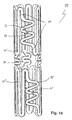
- FIGS. 1a to 2 illustrated expansion elements 12,12 '; 22 each have a serpentine geometric shape
- the - very schematically - in the FIGS. 3a to 3c illustrated embodiments of inventive expansion elements 32a, 32b, 32c each have the geometric course of a double spiral, which curves starting from a common center in two opposite directions of rotation.
- this double spiral is triangular, in Fig. 3b round and in Fig. 3c quadrangular.
- other geometric shapes such as instead of the rounded serpentine zigzag or meandering courses of the expansion elements, which are not shown in the drawing.
- FIGS. 1a to 1d illustrated embodiment is also characterized by the fact that a plurality of expansion elements 12, 12 '- here exactly two - are arranged in the longitudinal direction of the implant 10 in a row.
- these have the same geometric structure and can have the same but also different mechanical properties.
- connector elements 14 are arranged in this embodiment, the force introduction in the longitudinal direction of these webs 11', 11" permanent plastic enlargement of the implant 10 in the axial direction cause.
- these connector elements 14 fulfill a completely different function than the expansion elements 12, 12 'according to the invention and also do not form a web section within one of the webs 11, 11', 11 ", rather they sit axially between adjacent webs 11 ', 11” and can not cause radial expansion of the implant 10, but only an axial extension.
- the serpentine lines are "stretched" and now run only in short sections transverse to the longitudinal direction.
- the diameter d2 and thus the inner cross section of the implant 20 are considerably increased.
- the expansion element 22 is stretched so that the serpentine lines become practically straight. This results in the maximum diameter d3 and thus the largest internal cross-section of the implant 20.
- the bottleneck 23 designed as a predetermined breaking point is then defined.
- the expansion element according to the invention should be designed such that the largest possible extent of the clear cross section of the tubular implant in the radial direction from the minimally contracted to the maximum redilated state is made possible.
- the preparation of the implants 10 according to the invention; 20, in particular of the webs 11, 11 ', 11 ", 21, 21', 21" including the expansion elements 12, 12 '; 22; 32a, 32b, 32c preferably takes place from a tubular output part by laser cutting.
- the implant according to the invention receives on its surface at least in sections a biologically active coating, in particular a growth-inhibiting and / or a growth-promoting and / or an antibacterial coating.
Description
- Die Erfindung betrifft ein medizinisches Implantat zur Aufweitung und Stützung eines Körpergefäßes von dessen Innenseite her (="Stent"), das in einem kontrahierten Zustand minimal-invasiv in das Körpergefäß einsetzbar, dort positionierbar und in einen expandierten Zustand überführbar ist, wobei das Implantat röhrenförmig aus länglichen, eine Wand des Implantats bildenden Stegen aufgebaut ist, und wobei die Stege zumindest abschnittsweise derart plastisch verformbar sind, dass das Implantat im expandierten Zustand in radialer Richtung quer zur Längsachse der Stege dauerhaft aufgeweitet bleibt.
WO-A-2008/008291 beschreibt die technischen Merkmale des Oberbegriffs aus Anspruch 1. - Derartige Stents sind seit langem bekannt, beispielsweise auch aus der
DE 101 05 160 B4 . - Ein solcher Stent weist mindestens eine geometrische Struktur auf, die es erlaubt, dass er - meist über mehrere Stufen - aus seinem kontrahierten Zustand in einen aufgeweiteten Zustand überführt werden kann (="Redilatierung"). Allerdings kann der lichte Querschnitt des Stents ausgehend vom ursprünglichen Minimalquerschnitt jeweils nur auf ein vorbestimmtes Maximalmaß aufgedehnt werden. Eine weitere radiale Dilatierung ist nicht möglich, weil sich sonst der Stent undefiniert verformen und anschließend brechen würde. Für jede Gefäßgröße wird daher eine bestimmte Stentgröße hergestellt und verwendet, damit eine optimale radiale Haltekraft des Stents im Einzelfall sichergestellt werden kann.
- Bisher mögliche und übliche Aufweitungsgruppen sehen Querschnittsvergrößerungen des Stents (gemessen jeweils in Millimetern des lichten Durchmessers) auf 4 oder 6, auf 6 oder 8, auf 8 oder 10, auf 10 oder 12 vor. Noch größere Aufweitungen sind unüblich und werden in der Regel nur für Spezialanwendungen eingesetzt, wobei dann allerdings von bereits viel größeren Ausgangs- bzw. Minimalquerschnitten ausgegangen wird, also etwa Aufweitungen von 16mm auf 20mm Durchmesser.
- Eines der Hauptprobleme bei der Verwendung derartiger Stents liegt in den Anwendungen bei kleinen Kindern, insbesondere im Bereich der Kinder- und Säuglingskardiologie: Hier muss man aufgrund der geringen Gefäßgrößen der kleinen Patienten zunächst immer mit Stents sehr geringer Ausgangsquerschnitte arbeiten. Danach wächst das Kind jedoch zum Jugendlichen und schließlich zum Erwachsenen heran, die Gefäße vergrößern sich gegenüber dem Zeitpunkt der ersten Implantation enorm und die maximale Ausweitbarkeit des jeweils eingesetzten Stents ist sehr schnell erreicht, so dass der Stent im Verlauf in der Regel mindestens einmal gegen ein größeres Modell ausgetauscht werden muss. Dieser Austausch ist natürlich jedes Mal mit einer Operation verbunden, was für den heranwachsenden Patienten sehr belastend ist, selbst wenn minimal-invasive Techniken angewandt werden können.
- Aufgabe der vorliegenden Erfindung ist es demgegenüber, eine gattungsgemäße Anordnung der eingangs beschriebenen Art mit möglichst einfachen technischen Mitteln unaufwändig und kostengünstig dahin gehend zu verbessern, dass über das bislang baubedingte Maximalmaß der Redilatierung hinaus ein ganz erheblich größerer Bereich von Aufweitungen des Querschnitts des röhrenförmigen Implantats in Radialrichtung ausgehend vom minimal kontrahierten Ursprungszustand bis zum maximal redilatierten Endzustand ermöglicht wird, der es dann letztlich erlaubt, einen im Kindesalter eingesetzten Stent - wenn medizinisch möglich - bis zum Erwachsenenalter im Körper des Patienten zu belassen ("mitwachsender Kinderstent").
- Erfindungsgemäß wird diese Aufgabe auf ebenso überraschend einfache wie wirkungsvolle Weise dadurch gelöst, dass zumindest einer der Stege ein Dehnelement aufweist, welches einen Stegabschnitt innerhalb dieses Steges bildet, in dem das Dehnelement im kontrahierten Zustand teilweise geometrisch quer zur Längsachse des Steges verläuft, wobei der Verlauf des Dehnelements bezüglich dieser Längsachse mehrere Richtungsänderungen aufweist, und dass Material, Dicke und Stegbreite des Dehnelements derart gewählt sind, dass durch Krafteinleitung in Radialrichtung des röhrenförmigen Implantats das Dehnelement durch plastische Streckung in einen dauerhaft expandierten Zustand versetzt werden kann, in welchem der das Dehnelement bildende Stegabschnitt eine größere geometrische Ausdehnung quer zur Längsachse und eine geringere Ausdehnung in Richtung der Längsachse aufweist als im kontrahierten Zustand. Auf diese Weise lassen sich Redilatierungen in einem sehr weiten Bereich erzielen, die ganz erheblich über das bisher baubedingte Maximalmaß herkömmlicher Stents hinausgehen.
- Ganz besonders bevorzugt sind Ausführungsformen des erfindungsgemäßen Implantats, bei denen das Dehnelement aufgrund seiner Materialeigenschaften und seiner Geometrie so ausgebildet ist, dass eine Ausdehnung des Querschnittdurchmessers des röhrenförmigen Implantats in Radialrichtung vom minimal kontrahierten bis zum maximal redilatierten Zustand von 2mm auf 18mm, vorzugsweise von 4mm auf 16mm, oder von 6mm auf 24mm, vorzugsweise von 6mm auf 20mm, ermöglicht wird. Damit können in der Praxis die normalerweise vorkommenden Bereiche des menschlichen Wachstums vom Kleinkind bis zum Erwachsenen abgedeckt werden.
- Eine fertigungstechnisch besonders einfach und kompakt herstellbare Klasse von Ausführungsformen des erfindungsgemäßen Implantats zeichnet sich dadurch aus, dass das Dehnelement im kontrahierten Zustand zumindest abschnittsweise einen zickzackförmigen, schlangenlinienförmigen und/oder mäanderförmigen geometrischen Verlauf aufweist. Je nach Anzahl der Zickzack-Strukturen - die vorteilhaft in einander entgegengesetzten Richtungen angeordnet sein können - kann die Aufweitbarkeit des Stents, insbesondere im Vergleich zu herkömmlichen Stents nach dem Stand der Technik, ziemlich groß werden. Zudem weist ein erfindungsgemäßer Stent mit derartig geformten Dehnelementen aufgrund dieser Struktur unabhängig von der Redilationsstufe eine besonders große Radialkraft auf.
- In der Praxis bewährt sich aber auch eine andere Klasse von Ausführungsformen der Erfindung, bei denen das Dehnelement im kontrahierten Zustand zumindest abschnittsweise einen spiralförmigen geometrischen Verlauf aufweist.
- Besonders vorteilhaft sind Weiterbildungen, die sich dadurch auszeichnen, dass das Dehnelement im kontrahierten Zustand zumindest abschnittsweise den geometrischen Verlauf einer Doppelspirale aufweist, die sich ausgehend von einem gemeinsamen Mittelpunkt in zwei entgegengesetzten Drehrichtungen krümmt. Weiterbildungen dieser Ausführungsformen sind möglich, bei denen die Spirale eine runde, insbesondere kreisrunde, oder eine dreieckige oder eine viereckige, insbesondere quadratische, Außenkontur aufweist.
- Das Dehnelement des erfindungsgemäßen Implantats weist im kontrahierten Zustand eine Engstelle auf, deren Stegbreite geringer ist als die Stegbreiten der anschließenden Stegabschnitte.
- Die Stegbreite der Engstelle ist höchstens zwei Drittel, vorzugsweise höchstens halb so groß wie die Stegbreiten der anschließenden Stegabschnitte.
- Die Engstelle ist als Sollbruchstelle für das Dehnelement ausgelegt die bei zu großer Krafteinleitung in Radialrichtung des röhrenförmigen Implantats bricht, eine weitere Möglichkeit zur Redilatation eröffnet und dadurch eine weitere Expansion des Dehnelements verhindert. In diesem Fall wird dann zwar der entsprechende Steg des Implantats in Längsrichtung unterbrochen. Trotz dieser Unterbrechung kann aber in den meisten praktischen Anwendungsfällen auf die Implantation eines neuen Stents verzichtet werden, da sich das behandelte Gefäß nach einer derartigen Wachstumsperiode in der Regel bereits genügend stabilisiert hat, so der verbleibende gebrochene Stent als Stütze ausreicht.
- Wie bereits per se aus dem Stand der Technik bekannt ist, können zwischen Paaren von in Richtung der Längsachse des Implantats benachbarten Stegen Verbinderelemente angeordnet sein, die bei Krafteinleitung in Längsrichtung dieser Stege eine dauerhafte plastische Vergrößerung des Implantats in axialer Richtung bewirken.
- Bevorzugt ist eine Ausführungsform des erfindungsgemäßen Implantats, bei der mehrere Dehnelemente pro Stent vorgesehen sind, wodurch sich die Flexibilität und die Anwendungsbandbreite des Implantats erhöhen.
- Bei einer Klasse von Weiterbildungen dieser Ausführungsform weisen die Dehnelemente untereinander die gleichen mechanischen Eigenschaften auf und sind insbesondere geometrisch gleich aufgebaut, wodurch sich ein einheitlicher Herstellungsprozess anwenden lässt.
- Alternativ können bei einer anderen Klasse von Weiterbildungen die Dehnelemente untereinander unterschiedliche mechanischen Eigenschaften aufweisen. Dies ermöglicht eine große Bandbreite von individuell auf spezielle Probleme des Patienten angepassten Designs der erfindungsgemäße Implantate.
- Die unterschiedlichen mechanischen Eigenschaften der Dehnelemente können bei Varianten dieser Weiterbildungen dadurch erreicht werden, dass die Dehnelemente zwar geometrisch gleich aufgebaut sind, was ein einheitliches Herstellungsverfahren begünstigt, jedoch unterschiedliche Stegbreiten aufweisen.
- Eine andere Variante der Erfindung hingegen zeichnet sich dadurch aus, dass die Dehnelemente geometrisch unterschiedlich aufgebaut sind. Dies lässt wiederum eine große Vielfalt an unterschiedlichen, auf individuelle Problemlösungen abzielende Designs der Implantate zu.
- Bei bevorzugten Weiterbildungen der oben beschriebenen Ausführungsform können mehrere Dehnelemente in Längsrichtung des Implantats hintereinander angeordnet sein.
- Vorteilhaft sind auch Varianten, bei denen mehrere Dehnelemente azimutal, insbesondere symmetrisch, über den Umfang des Implantats verteilt angeordnet sind.
- Ganz besonders bevorzugt sind Ausführungsformen des erfindungsgemäßen Implantats, bei welchen die Stege einschließlich der Dehnelemente aus einem rohrförmigen Ausgangsteil, vorzugsweise durch Laserschneiden, hergestellt sind. Hiermit lassen sich auch besonders feine Strukturen und Konturen in reproduzierbarer Qualität und mittlerweile auch in großen Mengen erzeugen.
- Das erfindungsgemäße Implantat kann zumindest im Bereich des Dehnelements aus einem Material unter Verwendung von Chrom und/oder Kobalt und/oder Platin und/oder einer Legierung der genannten Metalle und/oder einer Edelstahllegierung hergestellt sein.
- Vorteilhaft für viele Anwendungen ist es auch wenn das Implantat zumindest im Bereich des Dehnelements aus einem Material mit Formgedächtnis (=memory effect), insbesondere aus Nitinol hergestellt ist, welches etwa durch Einwirkung von Wärme eine definierte - und bei Aufrechterhaltung der thermischen Bedingungen auch dauerhafte - Strukturänderung erfährt.
- Zumindest Teile des Implantats können auch aus biokompatiblen Kunststoffen, insbesondere Silikon oder Polytetrafluorethylen (PTFE), und/oder aus Faserverbund-Werkstoffen, insbesondere Kohlefasern hergestellt sein.
- Des Weiteren kommen als Werkstoffe für das erfindungsgemäße Implantat oder zumindest von Teilen desselben Titan und/oder Gold und/oder Tantal und/oder eine Legierung der genannten Metalle in Frage.
- Für spezielle Anwendungsfälle kann es aber auch von Nutzen sein, wenn zumindest Teile des Implantats aus einem Keramikmaterial hergestellt sind.
- Vorteilhaft sind schließlich auch Ausführungsformen der Erfindung, die sich dadurch auszeichnen, dass zumindest abschnittsweise auf der Oberfläche des Implantats eine biologisch aktive Beschichtung, insbesondere eine wachstumshemmende und/oder eine wachstumsfördernde und/oder eine antibakteriell wirkende Beschichtung, vorgesehen ist.
- Weitere Merkmale und Vorteile der Erfindung ergeben sich aus der nachfolgenden detaillierten Beschreibung von Ausführungsbeispielen der Erfindung anhand der Figuren der Zeichnung, die erfindungswesentliche Einzelheiten zeigt, sowie aus den Ansprüchen. Die einzelnen Merkmale können je einzeln für sich oder zu mehreren in beliebigen Kombinationen bei Varianten der Erfindung verwirklicht sein.
- In der schematischen Zeichnung sind Ausführungsbeispiele der Erfindung dargestellt, welche in der nachfolgenden Beschreibung näher erläutert werden.
- Im Einzelnen zeigen:
- Fign. 1a-d
- eine Ausführungsform des erfindungsgemäßen Implantats mit zwei in Längsrichtung hintereinander angeordneten, schlangenförmigen Dehnelementen in schematischer räumlicher Darstellung, nämlich 1a) von der Seite, 1b) von oben in Längsrichtung der Stege, 1c) räumlich schräg und 1d) vergrößert von der Seite;
- Fig. 2
- eine Ausführungsform mit nur einem Dehnelement sowie im Detail verschiedene Phasen der Aufdehnung des Implantats; und
- Fign. 3a-c
- Ausführungsformen von erfindungsgemäßen Dehnelementen in Form von Doppelspiralen, nämlich 3a) dreieckig, 3b) rund und 3c) viereckig.
- Die in den Figuren der Zeichnung schematisch dargestellten Ausführungsformen des erfindungsgemäßen medizinischen Implantats 10; 20 zur Aufweitung und Stützung eines Körpergefäßes von dessen Innenseite her (="Stent"), sind jeweils röhrenförmig aus länglichen, eine Wand des Implantats 10; 20 bildenden Stegen 11,11',11"; 21,21',21" aufgebaut, die zumindest abschnittsweise derart plastisch verformbar sind, dass das Implantat 10; 20 nach Redilatierung in radialer Richtung quer zur Längsachse der Stege 11,11',11"; 21,21',21" dauerhaft aufgeweitet bleibt. Um eine gegenüber bekannten Stents erheblich größere Aufweitbarkeit des Implantats 10; 20 zu erreichen, enthält zumindest einer der Stege 11; 21 ein Dehnelement 12,12'; 22; 32a,32b,32c, welches einen Stegabschnitt innerhalb dieses Steges 11; 21 bildet, in dem das Dehnelement 12,12'; 22; 32a,32b,32c im kontrahierten Zustand teilweise geometrisch quer zur Längsachse des Steges 11; 21 verläuft, wobei der Verlauf des Dehnelements 12,12'; 22; 32a,32b,32c bezüglich dieser Längsachse einige Richtungsänderungen aufweist. Material, Dicke und Stegbreite des Dehnelements 12,12'; 22; 32a,32b,32c sind derart gewählt, dass durch Krafteinleitung in Radialrichtung des röhrenförmigen Implantats 10; 20 das Dehnelement 12,12'; 22; 32a,32b,32c durch plastische Streckung in einen dauerhaft expandierten Zustand versetzt werden kann, in welchem der das Dehnelement 12,12'; 22; 32a,32b,32c bildende Stegabschnitt eine größere geometrische Ausdehnung quer zur Längsachse und eine geringere Ausdehnung in Richtung der Längsachse aufweist als im kontrahierten Zustand.
- Sämtliche in der Zeichnung dargestellten Ausführungsformen der Erfindung stimmen auch darin überein, dass die Dehnelemente 12,12'; 22; 32a,32b,32c jeweils eine als Sollbruchstelle ausgelegte Engstelle 13,13'; 23; 33a,33b,33c besitzen, die bei zu großer Krafteinleitung in Radialrichtung des röhrenförmigen Implantats 10; 20 bricht, eine weitere Möglichkeit zur Redilatation eröffnet und dadurch eine weitere Expansion des Dehnelements 12,12'; 22; 32a,32b,32c verhindert.
- Die in den
Figuren 1a bis 2 dargestellten Dehnelemente 12,12'; 22 weisen jeweils einen schlangenlinienförmigen geometrischen Verlauf auf, während die - sehr schematisch - in denFiguren 3a bis 3c dargestellten Ausführungsformen erfindungsgemäßer Dehnelemente 32a, 32b, 32c jeweils den geometrischen Verlauf einer Doppelspirale aufweisen, die sich ausgehend von einem gemeinsamen Mittelpunkt in zwei entgegengesetzten Drehrichtungen krümmt. Bei dem Ausführungsbeispiel inFig. 3a ist diese Doppelspirale dreieckig, inFig. 3b rund und inFig. 3c viereckig. Denkbar sind auch andere geometrische Formgebungen, etwa anstelle der abgerundeten Schlangenlinien zickzackförmige oder mäanderförmige Verläufe der Dehnelemente, die jedoch in der Zeichnung nicht dargestellt sind. - Die in den
Figuren 1a bis 1d dargestellte Ausführungsform zeichnet sich außerdem dadurch aus, dass mehrere Dehnelemente 12, 12' - hier genau zwei - in Längsrichtung des Implantats 10 hintereinander angeordnet sind. Diese sind im vorliegenden Ausführungsbeispiel geometrisch gleich aufgebaut und können die gleichen, aber auch unterschiedliche mechanischen Eigenschaften aufweisen. - Zwischen einigen Paaren von in Richtung der Längsachse des Implantats 10 benachbarten Stegen 11', 11" sind bei dieser Ausführungsform Verbinderelemente 14 angeordnet, die bei Krafteinleitung in Längsrichtung dieser Stege 11', 11" eine dauerhafte plastische Vergrößerung des Implantats 10 in axialer Richtung bewirken. Diese Verbinderelemente 14 erfüllen also eine völlig andere Funktion als die erfindungsgemäßen Dehnelemente 12, 12' und bilden auch keinen Stegabschnitt innerhalb eines der Stege 11, 11', 11". Vielmehr sitzen sie axial zwischen benachbarten Stegen 11', 11" und können auch keine radiale Aufweitung des Implantats 10 bewirken, sondern nur eine axiale Verlängerung.
- Bei in der Zeichnung nicht dargestellten Ausführungsformen des erfindungsgemäßen Implantats können auch mehrere Dehnelemente azimutal über den Umfang des Implantats verteilt angeordnet sein.
- In
Fig. 2 sind am Beispiel einer einfachen Ausführungsform mit nur einem einzigen - schlangenlinienförmigen - Dehnelement 22 im Steg 21 des Implantats 20 drei verschiedene Phasen der Aufweitung dargestellt: - Im ursprünglichen, maximal kontrahierten Zustand, in welchem das Implantat 20 in das Gefäß des Patienten eingeführt wird, verlaufen die Schlangenlinien des Dehnelements 22 noch in relativ langen Abschnitten quer zur Längsrichtung der Stege 21, 21' 21". Entsprechend ergibt sich ein minimaler Durchmesser d1 und damit ein minimaler lichter Innenquerschnitt des Implantats 20 an dieser Stelle.
- Nach Zuführung von Kraft in radialer Richtung dehnt sich das Dehnelement 22 - seiner Bestimmung gemäß - aus, die Schlangenlinien werden "gestreckt" und verlaufen nunmehr nur noch in kurzen Abschnitten quer zur Längsrichtung. Der Durchmesser d2 und damit der Innenquerschnitt des Implantats 20 werden erheblich vergrößert.
- In der dritten Phase schließlich wird das Dehnelement 22 derart gestreckt, dass die Schlangenlinien praktisch zu Geraden werden. Es ergibt sich damit der maximale Durchmesser d3 und damit der größte Innenquerschnitt des Implantats 20. Bei weiterer Krafteinleitung wird dann die als Sollbruchstelle ausgelegte Engstelle 23 definiert brechen.
- Das erfindungsgemäße Dehnelement soll aufgrund seiner Materialeigenschaften und seiner Geometrie so ausgebildet sein, dass eine möglichst große Ausdehnung des lichten Querschnitts des röhrenförmigen Implantats in Radialrichtung vom minimal kontrahierten bis zum maximal redilatierten Zustand ermöglicht wird. Realistisch sind Aufweitungen eines ursprünglichen Durchmessers d1 von 1,3mm auf einen Maximaldurchmesser d3 von 18mm oder von d1=2mm auf d3=24mm. In der Praxis wird man sich aber auch schon mit Aufweitungen von d1=3mm auf d3=20mm begnügen können. Auch damit wird schon eine Aufweitbarkeit des Stents auf ein Vielfaches des ursprünglichen Durchmessers erreicht.
- Die Herstellung der erfindungsgemäßen Implantate 10; 20, insbesondere der Stege 11,11',11"; 21,21',21" einschließlich der Dehnelemente 12,12'; 22; 32a,32b,32c erfolgt vorzugsweise aus einem rohrförmigen Ausgangsteil durch Laserschneiden.
- Vorteilhaft kann es auch sein, wenn das erfindungsgemäße Implantat zumindest abschnittsweise auf seiner Oberfläche eine biologisch aktive Beschichtung, insbesondere eine wachstumshemmende und/oder eine wachstumsfördernde und/oder eine antibakteriell wirkende Beschichtung, erhält.
Claims (15)
- Medizinisches Implantat (10; 20) zur Aufweitung und Stützung eines Körpergefäßes von dessen Innenseite her (="Stent"), das in einem kontrahierten Zustand, vorzugsweise minimal-invasiv, in das Körpergefäß einsetzbar, dort positionierbar und in einen expandierten Zustand überführbar ist, wobei das Implantat (10; 20) röhrenförmig aus länglichen, eine Wand des Implantats (10; 20) bildenden Stegen (11,11',11"; 21,21',21") aufgebaut ist, wobei die Stege (11,11',11"; 21,21',21") zumindest abschnittsweise derart plastisch verformbar sind, dass das Implantat (10; 20) im expandierten Zustand in radialer Richtung quer zur Längsachse der Stege (11,11',11"; 21,21',21") dauerhaft aufgeweitet bleibt, und wobei zumindest einer der Stege (11; 21) ein Dehnelement (12,12'; 22; 32a,32b,32c) aufweist, welches einen Stegabschnitt innerhalb dieses Steges (11; 21) bildet, in dem das Dehnelement (12,12'; 22; 32a,32b,32c) im kontrahierten Zustand teilweise geometrisch quer zur Längsachse des Steges (11; 21) verläuft, wobei der Verlauf des Dehnelements (12,12'; 22; 32a,32b,32c) bezüglich dieser Längsachse mehrere Richtungsänderungen aufweist,
dadurch gekennzeichet,
dass Material, Dicke und Stegbreite des Dehnelements (12,12'; 22; 32a,32b,32c) derart gewählt sind, dass durch Krafteinleitung in Radialrichtung des röhrenförmigen Implantats (10; 20) das Dehnelement (12,12'; 22; 32a,32b,32c) durch plastische Streckung in einen dauerhaft expandierten Zustand versetzt werden kann, in welchem der das Dehnelement (12,12'; 22; 32a,32b,32c) bildende Stegabschnitt eine größere geometrische Ausdehnung quer zur Längsachse und eine geringere Ausdehnung in Richtung der Längsachse aufweist als im kontrahierten Zustand,
dass das Dehnelement (12,12'; 22; 32a,32b,32c) im kontrahierten Zustand eine Engstelle (13,13'; 23; 33a,33b, 33c) aufweist, deren Stegbreite geringer ist als die Stegbreiten der anschließenden Stegabschnitte,
dass die Stegbreite der Engstelle (13,13'; 23; 33a,33b,33c) höchstens zwei Drittel so groß ist wie die Stegbreiten der anschließenden Stegabschnitte, und
dass die Engstelle (13,13'; 23; 33a,33b,33c) als Sollbruchstelle für das Dehnelement (12,12'; 22; 32a,32b,32c) ausgelegt ist, die bei zu großer Krafteinleitung in Radialrichtung des röhrenförmigen Implantats (10; 20) bricht, eine weitere Möglichkeit zur Redilatation eröffnet und dadurch eine weitere Expansion des Dehnelements (12,12'; 22; 32a,32b,32c) verhindert. - Implantat nach Anspruch 1, dadurch gekennzeichnet, dass das Dehnelement (12,12'; 22) aufgrund seiner Materialeigenschaften und seiner Geometrie so ausgebildet ist, dass eine Ausdehnung des Querschnitts des röhrenförmigen Implantats (10; 20) in Radialrichtung vom minimal kontrahierten bis zum maximal redilatierten Zustand von 2mm auf 18mm, vorzugsweise von 4mm auf 16mm, oder von 6mm auf 24mm, vorzugsweise von 6mm auf 20mm, ermöglicht wird.
- Implantat nach einem der Ansprüche 1 oder 2, dadurch gekennzeichnet, dass das Dehnelement (12,12'; 22) im kontrahierten Zustand zumindest abschnittsweise einen zickzackförmigen, schlangenlinienförmigen und/oder mäanderförmigen geometrischen Verlauf aufweist.
- Implantat nach einem der Ansprüche 1 oder 2, dadurch gekennzeichnet, dass das Dehnelement (32a, 32b, 32c) im kontrahierten Zustand zumindest abschnittsweise einen spiralförmigen geometrischen Verlauf aufweist.
- Implantat nach Anspruch 4, dadurch gekennzeichnet, dass das Dehnelement (32a, 32b, 32c) im kontrahierten Zustand zumindest abschnittsweise den geometrischen Verlauf einer Doppelspirale aufweist, die sich ausgehend von einem gemeinsamen Mittelpunkt in zwei entgegengesetzten Drehrichtungen krümmt.
- Implantat nach einem der Ansprüche 4 oder 5, dadurch gekennzeichnet, dass die Spirale eine runde (32b), insbesondere kreisrunde, oder eine dreieckige (32a) oder eine viereckige (32c), insbesondere quadratische Außenkontur aufweist.
- Implantat nach einem der vorhergehenden Ansprüche, dadurch gekennzeichnet, dass die Stegbreite der Engstelle (13,13'; 23; 33a,33b,33c) höchstens halb so groß ist wie die Stegbreiten der anschließenden Stegabschnitte.
- Implantat nach einem der vorhergehenden Ansprüche, dadurch gekennzeichnet, dass zwischen Paaren von in Richtung der Längsachse des Implantats (10) benachbarten Stegen (11', 11") Verbinderelemente (14) angeordnet sind, die bei Krafteinleitung in Längsrichtung dieser Stege (11', 11") eine dauerhafte plastische Vergrößerung des Implantats (10) in axialer Richtung bewirken.
- Implantat nach einem der vorhergehenden Ansprüche, dadurch gekennzeichnet, dass mehrere Dehnelemente (12,12'; 32a,32b, 32c) vorgesehen sind.
- Implantat nach Anspruch 9, dadurch gekennzeichnet, dass die Dehnelemente (12,12') die gleichen mechanischen Eigenschaften aufweisen, insbesondere geometrisch gleich aufgebaut sind.
- Implantat nach Anspruch 9, dadurch gekennzeichnet, dass die Dehnelemente (12,12'; 32a,32b,32c) unterschiedliche mechanischen Eigenschaften aufweisen.
- Implantat nach Anspruch 11, dadurch gekennzeichnet, dass die Dehnelemente (12,12') geometrisch gleich aufgebaut sind, aber unterschiedliche Stegbreiten aufweisen.
- Implantat nach Anspruch 11, dadurch gekennzeichnet, dass die Dehnelemente (32a, 32b, 32c) geometrisch unterschiedlich aufgebaut sind.
- Implantat nach einem der Ansprüche 9 bis 13, dadurch gekennzeichnet, dass mehrere Dehnelemente (12, 12') in Längsrichtung des Implantats (10) hintereinander angeordnet sind.
- Implantat nach einem der Ansprüche 9 bis 14, dadurch gekennzeichnet, dass mehrere Dehnelemente azimutal über den Umfang des Implantats verteilt angeordnet sind.
Priority Applications (1)
| Application Number | Priority Date | Filing Date | Title |
|---|---|---|---|
| PL09744929T PL2477583T3 (pl) | 2009-09-16 | 2009-09-16 | Stent wyposażony w element rozciągalny |
Applications Claiming Priority (1)
| Application Number | Priority Date | Filing Date | Title |
|---|---|---|---|
| PCT/DE2009/001306 WO2011032526A1 (de) | 2009-09-16 | 2009-09-16 | Stent mit dehnelementen |
Publications (2)
| Publication Number | Publication Date |
|---|---|
| EP2477583A1 EP2477583A1 (de) | 2012-07-25 |
| EP2477583B1 true EP2477583B1 (de) | 2015-04-08 |
Family
ID=42122802
Family Applications (1)
| Application Number | Title | Priority Date | Filing Date |
|---|---|---|---|
| EP09744929.2A Active EP2477583B1 (de) | 2009-09-16 | 2009-09-16 | Stent mit dehnelementen |
Country Status (10)
| Country | Link |
|---|---|
| US (1) | US8852268B2 (de) |
| EP (1) | EP2477583B1 (de) |
| JP (1) | JP5572881B2 (de) |
| CN (1) | CN102655825B (de) |
| BR (1) | BR112012008334B8 (de) |
| DE (1) | DE112009005236A5 (de) |
| ES (1) | ES2541465T3 (de) |
| PL (1) | PL2477583T3 (de) |
| RU (1) | RU2506933C2 (de) |
| WO (1) | WO2011032526A1 (de) |
Families Citing this family (18)
| Publication number | Priority date | Publication date | Assignee | Title |
|---|---|---|---|---|
| US9220615B2 (en) * | 2011-02-23 | 2015-12-29 | Celonova Stent, Inc. | Stent having at least one connecting member configured to controllably sever in vivo |
| CA2855943C (en) | 2011-07-29 | 2019-10-29 | Carnegie Mellon University | Artificial valved conduits for cardiac reconstructive procedures and methods for their production |
| CN111772877A (zh) * | 2013-03-08 | 2020-10-16 | 卡内基梅隆大学 | 可扩展的可植入导管 |
| CN105208977B (zh) * | 2013-03-13 | 2020-06-09 | 波士顿科学国际有限公司 | 用于完全被覆盖支架的防止迁移组织锚固系统 |
| US9381103B2 (en) * | 2014-10-06 | 2016-07-05 | Abbott Cardiovascular Systems Inc. | Stent with elongating struts |
| DE102015108835A1 (de) | 2015-06-03 | 2016-12-08 | Andratec Gmbh | Gefäßstütze |
| DE102015115279A1 (de) * | 2015-09-10 | 2017-03-16 | Bentley Innomed Gmbh | Expandierbare Gefäßstütze |
| US11000370B2 (en) | 2016-03-02 | 2021-05-11 | Peca Labs, Inc. | Expandable implantable conduit |
| CN109069270B (zh) * | 2016-04-27 | 2020-10-16 | 海峡接入控股(私人)有限公司 | 可扩张支架及压握和扩张此类支架的方法 |
| CN106236339B (zh) * | 2016-07-22 | 2018-06-01 | 江苏大学 | 一种适用于分叉血管主支的锥形血管支架 |
| US10610357B2 (en) | 2016-10-10 | 2020-04-07 | Peca Labs, Inc. | Transcatheter stent and valve assembly |
| CN109833521B (zh) * | 2017-11-29 | 2021-10-26 | 郑州大学 | 一种制备人工血管的方法及装置 |
| US11389312B2 (en) | 2018-01-16 | 2022-07-19 | Sintra Medical Llc | Stents with increased flexibility |
| AU2019290674B2 (en) * | 2018-06-20 | 2022-08-18 | W. L. Gore & Associates, Inc. | Support structure for an implantable device with enhanced compressive stiffness region(s) |
| US10702407B1 (en) * | 2019-02-28 | 2020-07-07 | Renata Medical, Inc. | Growth stent for congenital narrowings |
| CN110345138B (zh) * | 2019-06-21 | 2021-02-26 | 华中科技大学 | 基于4d打印的仿生智能分离连接装置 |
| DE102020211175A1 (de) * | 2020-09-04 | 2022-03-10 | Carl Zeiss Meditec Ag | Stent-Implantat zur Glaukom-Behandlung durch Kammerwasserdrainage aus der Vorderkammer |
| ES2914516A1 (es) * | 2022-01-07 | 2022-06-13 | Conic Vascular Espana Sl | Stent pediatrico autoexpandible |
Family Cites Families (31)
| Publication number | Priority date | Publication date | Assignee | Title |
|---|---|---|---|---|
| US5383926A (en) * | 1992-11-23 | 1995-01-24 | Children's Medical Center Corporation | Re-expandable endoprosthesis |
| NZ285241A (en) * | 1995-04-26 | 1999-03-29 | Medinol Ltd | Articulated stent with area of inflection between neighbouring portions |
| JPH11509754A (ja) * | 1995-07-25 | 1999-08-31 | メドステント・インコーポレーテッド | 膨張型ステント |
| US6261318B1 (en) * | 1995-07-25 | 2001-07-17 | Medstent Inc. | Expandable stent |
| US6033433A (en) * | 1997-04-25 | 2000-03-07 | Scimed Life Systems, Inc. | Stent configurations including spirals |
| WO1999001088A1 (fr) * | 1997-07-04 | 1999-01-14 | Alain Fouere | Prothese vasculaire interne expansible et cintrable a usage chirurgical |
| US6241762B1 (en) * | 1998-03-30 | 2001-06-05 | Conor Medsystems, Inc. | Expandable medical device with ductile hinges |
| US6264687B1 (en) * | 1998-04-20 | 2001-07-24 | Cordis Corporation | Multi-laminate stent having superelastic articulated sections |
| US6425855B2 (en) * | 1999-04-06 | 2002-07-30 | Cordis Corporation | Method for making a multi-laminate stent having superelastic articulated sections |
| US8016873B1 (en) * | 1999-05-03 | 2011-09-13 | Drasler William J | Intravascular hinge stent |
| US6764507B2 (en) * | 2000-10-16 | 2004-07-20 | Conor Medsystems, Inc. | Expandable medical device with improved spatial distribution |
| EP2286770A1 (de) * | 2000-10-16 | 2011-02-23 | Conor Medsystems, Inc. | Expandierbare medizinische Vorrichtung zur Freisetzung eines Heilmittels |
| NO335594B1 (no) * | 2001-01-16 | 2015-01-12 | Halliburton Energy Serv Inc | Ekspanderbare anordninger og fremgangsmåte for disse |
| DE10103000B4 (de) | 2001-01-24 | 2007-08-30 | Qualimed Innovative Medizinprodukte Gmbh | Radial reexpandierbare Gefäßstütze |
| JP5011604B2 (ja) | 2001-02-01 | 2012-08-29 | 株式会社カネカ | ステント |
| DE10105160B4 (de) | 2001-02-06 | 2005-09-01 | Osypka, Peter, Dr.-Ing. | Implantierbare Gefäßstütze |
| US20030014102A1 (en) * | 2001-06-27 | 2003-01-16 | James Hong | Intravascular Stent |
| US6776794B1 (en) * | 2001-11-28 | 2004-08-17 | Advanced Cardiovascular Systems, Inc. | Stent pattern with mirror image |
| US7288111B1 (en) * | 2002-03-26 | 2007-10-30 | Thoratec Corporation | Flexible stent and method of making the same |
| WO2004045452A2 (en) * | 2002-11-15 | 2004-06-03 | Gmp/Cardiac Care, Inc. | Rail stent-graft for repairing abdominal aortic aneurysm |
| DE10355986A1 (de) * | 2003-11-27 | 2005-06-30 | Forschungszentrum Karlsruhe Gmbh | Kompressionsmanschette |
| US7429268B2 (en) * | 2004-12-08 | 2008-09-30 | Innovational Holdings, Llc | Expandable medical device with differential hinge performance |
| US7837726B2 (en) * | 2005-03-14 | 2010-11-23 | Abbott Laboratories | Visible endoprosthesis |
| US20070078511A1 (en) * | 2005-09-30 | 2007-04-05 | Boston Scientific Scimed, Inc. | Hybrid bifurcated stent |
| US20070112418A1 (en) * | 2005-11-14 | 2007-05-17 | Boston Scientific Scimed, Inc. | Stent with spiral side-branch support designs |
| DE102006017028A1 (de) * | 2006-04-11 | 2007-10-18 | Admedes Schuessler Gmbh | Selbstexpandierender Stent mit Federstruktur |
| WO2008008291A2 (en) | 2006-07-13 | 2008-01-17 | Icon Medical Corp. | Stent |
| WO2008062914A1 (en) * | 2006-11-23 | 2008-05-29 | Tovis Co., Ltd | Display apparatus having various shape |
| US8182890B2 (en) * | 2007-01-19 | 2012-05-22 | Elixir Medical Corporation | Biodegradable endoprostheses and methods for their fabrication |
| EP1958598A1 (de) * | 2007-02-16 | 2008-08-20 | Universität Zürich | Wachstumsfähige, rohrförmige Stützprothese |
| RU2349290C1 (ru) * | 2007-05-14 | 2009-03-20 | Российская Федерация в лице Федерального агентства по атомной энергии | Средство для поддержания просвета сосуда или полого органа и его варианты |
-
2009
- 2009-09-16 DE DE112009005236T patent/DE112009005236A5/de active Pending
- 2009-09-16 BR BR112012008334A patent/BR112012008334B8/pt active IP Right Grant
- 2009-09-16 ES ES09744929.2T patent/ES2541465T3/es active Active
- 2009-09-16 CN CN200980161563.6A patent/CN102655825B/zh active Active
- 2009-09-16 JP JP2012529117A patent/JP5572881B2/ja active Active
- 2009-09-16 WO PCT/DE2009/001306 patent/WO2011032526A1/de active Application Filing
- 2009-09-16 RU RU2012114894/14A patent/RU2506933C2/ru active
- 2009-09-16 EP EP09744929.2A patent/EP2477583B1/de active Active
- 2009-09-16 US US13/391,730 patent/US8852268B2/en active Active
- 2009-09-16 PL PL09744929T patent/PL2477583T3/pl unknown
Also Published As
| Publication number | Publication date |
|---|---|
| RU2012114894A (ru) | 2013-10-27 |
| DE112009005236A5 (de) | 2012-11-15 |
| CN102655825A (zh) | 2012-09-05 |
| US8852268B2 (en) | 2014-10-07 |
| JP2013504395A (ja) | 2013-02-07 |
| JP5572881B2 (ja) | 2014-08-20 |
| BR112012008334B1 (pt) | 2020-11-10 |
| WO2011032526A1 (de) | 2011-03-24 |
| US20120158125A1 (en) | 2012-06-21 |
| CN102655825B (zh) | 2015-07-08 |
| BR112012008334B8 (pt) | 2021-06-22 |
| ES2541465T3 (es) | 2015-07-20 |
| PL2477583T3 (pl) | 2015-08-31 |
| RU2506933C2 (ru) | 2014-02-20 |
| EP2477583A1 (de) | 2012-07-25 |
Similar Documents
| Publication | Publication Date | Title |
|---|---|---|
| EP2477583B1 (de) | Stent mit dehnelementen | |
| DE60031490T2 (de) | Stents für Angioplastie | |
| EP1827301B1 (de) | Stützprothese | |
| DE69630635T2 (de) | Implantierbare Prothese für ein menschliches oder tierisches Gefäss, wie z.B. Stent oder Aneurismaprothese | |
| DE60021836T2 (de) | Herstellungsverfahren eines Monoblockblutfilters | |
| DE69830520T2 (de) | Stent für Angioplastie | |
| DE10253633B4 (de) | Tragstruktur | |
| WO2016193449A1 (de) | GEFÄßSTÜTZE | |
| DE112004002651T5 (de) | In Längsrichtung flexibler Stent | |
| EP0711135A1 (de) | Stent | |
| WO2000071053A1 (de) | Radial expandierbare gefässstütze | |
| EP1419793A1 (de) | Endoprothese mit einer Trägerstruktur aus einer Magnesiumlegierung | |
| DE19633901A1 (de) | Gefäßstütze in Form einer Schlauchabschnitts-artigen Stützstruktur | |
| WO2001089414A1 (de) | Radial expandierbare gefässstütze | |
| EP1557138A1 (de) | Expandierbarer Stent mit Koppeleinrichtung | |
| DE102012107175B4 (de) | Medizinische Verschlussvorrichtung und System mit einer derartigen Verschlussvorrichtung | |
| EP2628468B1 (de) | Medizinische Vorrichtung | |
| EP1555959B1 (de) | Stent zur implantation in oder um ein hohlorgan | |
| DE202009012562U1 (de) | Stent mit Dehnelementen | |
| DE69917739T2 (de) | Expandierbarer stent | |
| EP2355754B1 (de) | Implantat | |
| DE102016117398B4 (de) | Expandierbare Struktur | |
| EP0884987A1 (de) | Expandierbare intraluminale vorrichtung | |
| EP2332499B1 (de) | Endoprothese | |
| DE19923133B4 (de) | Radial expandierbare Gefäßstütze |
Legal Events
| Date | Code | Title | Description |
|---|---|---|---|
| PUAI | Public reference made under article 153(3) epc to a published international application that has entered the european phase |
Free format text: ORIGINAL CODE: 0009012 |
|
| 17P | Request for examination filed |
Effective date: 20120202 |
|
| AK | Designated contracting states |
Kind code of ref document: A1 Designated state(s): AT BE BG CH CY CZ DE DK EE ES FI FR GB GR HR HU IE IS IT LI LT LU LV MC MK MT NL NO PL PT RO SE SI SK SM TR |
|
| DAX | Request for extension of the european patent (deleted) | ||
| RIC1 | Information provided on ipc code assigned before grant |
Ipc: A61F 2/91 20130101ALN20140711BHEP Ipc: A61F 2/915 20130101AFI20140711BHEP |
|
| GRAP | Despatch of communication of intention to grant a patent |
Free format text: ORIGINAL CODE: EPIDOSNIGR1 |
|
| REG | Reference to a national code |
Ref country code: DE Ref legal event code: R079 Ref document number: 502009010887 Country of ref document: DE Free format text: PREVIOUS MAIN CLASS: A61F0002900000 Ipc: A61F0002915000 |
|
| INTG | Intention to grant announced |
Effective date: 20140826 |
|
| RIC1 | Information provided on ipc code assigned before grant |
Ipc: A61F 2/91 20130101ALN20140910BHEP Ipc: A61F 2/915 20130101AFI20140910BHEP |
|
| GRAP | Despatch of communication of intention to grant a patent |
Free format text: ORIGINAL CODE: EPIDOSNIGR1 |
|
| RAP1 | Party data changed (applicant data changed or rights of an application transferred) |
Owner name: BENTLEY INNOMED GMBH |
|
| INTG | Intention to grant announced |
Effective date: 20141103 |
|
| GRAS | Grant fee paid |
Free format text: ORIGINAL CODE: EPIDOSNIGR3 |
|
| GRAA | (expected) grant |
Free format text: ORIGINAL CODE: 0009210 |
|
| AK | Designated contracting states |
Kind code of ref document: B1 Designated state(s): AT BE BG CH CY CZ DE DK EE ES FI FR GB GR HR HU IE IS IT LI LT LU LV MC MK MT NL NO PL PT RO SE SI SK SM TR |
|
| REG | Reference to a national code |
Ref country code: GB Ref legal event code: FG4D Free format text: NOT ENGLISH |
|
| REG | Reference to a national code |
Ref country code: CH Ref legal event code: EP |
|
| REG | Reference to a national code |
Ref country code: IE Ref legal event code: FG4D Free format text: LANGUAGE OF EP DOCUMENT: GERMAN |
|
| REG | Reference to a national code |
Ref country code: AT Ref legal event code: REF Ref document number: 719929 Country of ref document: AT Kind code of ref document: T Effective date: 20150515 |
|
| REG | Reference to a national code |
Ref country code: DE Ref legal event code: R096 Ref document number: 502009010887 Country of ref document: DE Effective date: 20150521 |
|
| REG | Reference to a national code |
Ref country code: CH Ref legal event code: NV Representative=s name: ROTTMANN, ZIMMERMANN + PARTNER AG, CH |
|
| REG | Reference to a national code |
Ref country code: NL Ref legal event code: T3 |
|
| REG | Reference to a national code |
Ref country code: SE Ref legal event code: TRGR |
|
| REG | Reference to a national code |
Ref country code: ES Ref legal event code: FG2A Ref document number: 2541465 Country of ref document: ES Kind code of ref document: T3 Effective date: 20150720 |
|
| REG | Reference to a national code |
Ref country code: FR Ref legal event code: PLFP Year of fee payment: 7 |
|
| REG | Reference to a national code |
Ref country code: PL Ref legal event code: T3 |
|
| REG | Reference to a national code |
Ref country code: LT Ref legal event code: MG4D |
|
| PG25 | Lapsed in a contracting state [announced via postgrant information from national office to epo] |
Ref country code: LT Free format text: LAPSE BECAUSE OF FAILURE TO SUBMIT A TRANSLATION OF THE DESCRIPTION OR TO PAY THE FEE WITHIN THE PRESCRIBED TIME-LIMIT Effective date: 20150408 Ref country code: HR Free format text: LAPSE BECAUSE OF FAILURE TO SUBMIT A TRANSLATION OF THE DESCRIPTION OR TO PAY THE FEE WITHIN THE PRESCRIBED TIME-LIMIT Effective date: 20150408 Ref country code: FI Free format text: LAPSE BECAUSE OF FAILURE TO SUBMIT A TRANSLATION OF THE DESCRIPTION OR TO PAY THE FEE WITHIN THE PRESCRIBED TIME-LIMIT Effective date: 20150408 Ref country code: PT Free format text: LAPSE BECAUSE OF FAILURE TO SUBMIT A TRANSLATION OF THE DESCRIPTION OR TO PAY THE FEE WITHIN THE PRESCRIBED TIME-LIMIT Effective date: 20150810 Ref country code: NO Free format text: LAPSE BECAUSE OF FAILURE TO SUBMIT A TRANSLATION OF THE DESCRIPTION OR TO PAY THE FEE WITHIN THE PRESCRIBED TIME-LIMIT Effective date: 20150708 |
|
| PG25 | Lapsed in a contracting state [announced via postgrant information from national office to epo] |
Ref country code: LV Free format text: LAPSE BECAUSE OF FAILURE TO SUBMIT A TRANSLATION OF THE DESCRIPTION OR TO PAY THE FEE WITHIN THE PRESCRIBED TIME-LIMIT Effective date: 20150408 Ref country code: GR Free format text: LAPSE BECAUSE OF FAILURE TO SUBMIT A TRANSLATION OF THE DESCRIPTION OR TO PAY THE FEE WITHIN THE PRESCRIBED TIME-LIMIT Effective date: 20150709 Ref country code: IS Free format text: LAPSE BECAUSE OF FAILURE TO SUBMIT A TRANSLATION OF THE DESCRIPTION OR TO PAY THE FEE WITHIN THE PRESCRIBED TIME-LIMIT Effective date: 20150808 |
|
| REG | Reference to a national code |
Ref country code: DE Ref legal event code: R097 Ref document number: 502009010887 Country of ref document: DE |
|
| PG25 | Lapsed in a contracting state [announced via postgrant information from national office to epo] |
Ref country code: EE Free format text: LAPSE BECAUSE OF FAILURE TO SUBMIT A TRANSLATION OF THE DESCRIPTION OR TO PAY THE FEE WITHIN THE PRESCRIBED TIME-LIMIT Effective date: 20150408 Ref country code: DK Free format text: LAPSE BECAUSE OF FAILURE TO SUBMIT A TRANSLATION OF THE DESCRIPTION OR TO PAY THE FEE WITHIN THE PRESCRIBED TIME-LIMIT Effective date: 20150408 |
|
| PLBE | No opposition filed within time limit |
Free format text: ORIGINAL CODE: 0009261 |
|
| STAA | Information on the status of an ep patent application or granted ep patent |
Free format text: STATUS: NO OPPOSITION FILED WITHIN TIME LIMIT |
|
| PG25 | Lapsed in a contracting state [announced via postgrant information from national office to epo] |
Ref country code: SK Free format text: LAPSE BECAUSE OF FAILURE TO SUBMIT A TRANSLATION OF THE DESCRIPTION OR TO PAY THE FEE WITHIN THE PRESCRIBED TIME-LIMIT Effective date: 20150408 Ref country code: RO Free format text: LAPSE BECAUSE OF NON-PAYMENT OF DUE FEES Effective date: 20150408 |
|
| 26N | No opposition filed |
Effective date: 20160111 |
|
| PG25 | Lapsed in a contracting state [announced via postgrant information from national office to epo] |
Ref country code: LU Free format text: LAPSE BECAUSE OF FAILURE TO SUBMIT A TRANSLATION OF THE DESCRIPTION OR TO PAY THE FEE WITHIN THE PRESCRIBED TIME-LIMIT Effective date: 20150916 Ref country code: MC Free format text: LAPSE BECAUSE OF FAILURE TO SUBMIT A TRANSLATION OF THE DESCRIPTION OR TO PAY THE FEE WITHIN THE PRESCRIBED TIME-LIMIT Effective date: 20150408 |
|
| PG25 | Lapsed in a contracting state [announced via postgrant information from national office to epo] |
Ref country code: SI Free format text: LAPSE BECAUSE OF FAILURE TO SUBMIT A TRANSLATION OF THE DESCRIPTION OR TO PAY THE FEE WITHIN THE PRESCRIBED TIME-LIMIT Effective date: 20150408 |
|
| REG | Reference to a national code |
Ref country code: IE Ref legal event code: MM4A |
|
| PG25 | Lapsed in a contracting state [announced via postgrant information from national office to epo] |
Ref country code: IE Free format text: LAPSE BECAUSE OF NON-PAYMENT OF DUE FEES Effective date: 20150916 |
|
| REG | Reference to a national code |
Ref country code: FR Ref legal event code: PLFP Year of fee payment: 8 |
|
| REG | Reference to a national code |
Ref country code: CH Ref legal event code: PCAR Free format text: NEW ADDRESS: GARTENSTRASSE 28 A, 5400 BADEN (CH) |
|
| REG | Reference to a national code |
Ref country code: AT Ref legal event code: MM01 Ref document number: 719929 Country of ref document: AT Kind code of ref document: T Effective date: 20150916 |
|
| PG25 | Lapsed in a contracting state [announced via postgrant information from national office to epo] |
Ref country code: AT Free format text: LAPSE BECAUSE OF NON-PAYMENT OF DUE FEES Effective date: 20150916 |
|
| PG25 | Lapsed in a contracting state [announced via postgrant information from national office to epo] |
Ref country code: MT Free format text: LAPSE BECAUSE OF FAILURE TO SUBMIT A TRANSLATION OF THE DESCRIPTION OR TO PAY THE FEE WITHIN THE PRESCRIBED TIME-LIMIT Effective date: 20150408 |
|
| PG25 | Lapsed in a contracting state [announced via postgrant information from national office to epo] |
Ref country code: HU Free format text: LAPSE BECAUSE OF FAILURE TO SUBMIT A TRANSLATION OF THE DESCRIPTION OR TO PAY THE FEE WITHIN THE PRESCRIBED TIME-LIMIT; INVALID AB INITIO Effective date: 20090916 Ref country code: BG Free format text: LAPSE BECAUSE OF FAILURE TO SUBMIT A TRANSLATION OF THE DESCRIPTION OR TO PAY THE FEE WITHIN THE PRESCRIBED TIME-LIMIT Effective date: 20150408 Ref country code: SM Free format text: LAPSE BECAUSE OF FAILURE TO SUBMIT A TRANSLATION OF THE DESCRIPTION OR TO PAY THE FEE WITHIN THE PRESCRIBED TIME-LIMIT Effective date: 20150408 |
|
| PG25 | Lapsed in a contracting state [announced via postgrant information from national office to epo] |
Ref country code: CY Free format text: LAPSE BECAUSE OF FAILURE TO SUBMIT A TRANSLATION OF THE DESCRIPTION OR TO PAY THE FEE WITHIN THE PRESCRIBED TIME-LIMIT Effective date: 20150408 |
|
| REG | Reference to a national code |
Ref country code: FR Ref legal event code: PLFP Year of fee payment: 9 |
|
| PG25 | Lapsed in a contracting state [announced via postgrant information from national office to epo] |
Ref country code: MK Free format text: LAPSE BECAUSE OF FAILURE TO SUBMIT A TRANSLATION OF THE DESCRIPTION OR TO PAY THE FEE WITHIN THE PRESCRIBED TIME-LIMIT Effective date: 20150408 |
|
| REG | Reference to a national code |
Ref country code: FR Ref legal event code: PLFP Year of fee payment: 10 |
|
| REG | Reference to a national code |
Ref country code: NL Ref legal event code: PD Owner name: MOB TECH GMBH; DE Free format text: DETAILS ASSIGNMENT: CHANGE OF OWNER(S), ASSIGNMENT; FORMER OWNER NAME: BENTLEY INNOMED GMBH Effective date: 20210824 |
|
| REG | Reference to a national code |
Ref country code: GB Ref legal event code: 732E Free format text: REGISTERED BETWEEN 20210826 AND 20210901 |
|
| REG | Reference to a national code |
Ref country code: BE Ref legal event code: PD Owner name: MOB TECH GMBH; DE Free format text: DETAILS ASSIGNMENT: CHANGE OF OWNER(S), ASSIGNMENT; FORMER OWNER NAME: BENTLEY INNOMED GMBH Effective date: 20210812 |
|
| REG | Reference to a national code |
Ref country code: DE Ref legal event code: R081 Ref document number: 502009010887 Country of ref document: DE Owner name: MOB TECH GMBH, DE Free format text: FORMER OWNER: BENTLEY INNOMED GMBH, 72379 HECHINGEN, DE |
|
| REG | Reference to a national code |
Ref country code: DE Ref legal event code: R082 Ref document number: 502009010887 Country of ref document: DE Representative=s name: SCHNEIDERS & BEHRENDT PARTMBB, RECHTS- UND PAT, DE |
|
| REG | Reference to a national code |
Ref country code: ES Ref legal event code: PC2A Owner name: MOB TECH GMBH Effective date: 20211027 |
|
| P01 | Opt-out of the competence of the unified patent court (upc) registered |
Effective date: 20230530 |
|
| PGFP | Annual fee paid to national office [announced via postgrant information from national office to epo] |
Ref country code: TR Payment date: 20230914 Year of fee payment: 15 Ref country code: NL Payment date: 20230920 Year of fee payment: 15 Ref country code: GB Payment date: 20230920 Year of fee payment: 15 Ref country code: CZ Payment date: 20230912 Year of fee payment: 15 |
|
| PGFP | Annual fee paid to national office [announced via postgrant information from national office to epo] |
Ref country code: SE Payment date: 20230925 Year of fee payment: 15 Ref country code: PL Payment date: 20230911 Year of fee payment: 15 Ref country code: FR Payment date: 20230928 Year of fee payment: 15 Ref country code: DE Payment date: 20230920 Year of fee payment: 15 Ref country code: BE Payment date: 20230920 Year of fee payment: 15 |
|
| PGFP | Annual fee paid to national office [announced via postgrant information from national office to epo] |
Ref country code: ES Payment date: 20231124 Year of fee payment: 15 |
|
| PGFP | Annual fee paid to national office [announced via postgrant information from national office to epo] |
Ref country code: IT Payment date: 20230927 Year of fee payment: 15 Ref country code: CH Payment date: 20231010 Year of fee payment: 15 |