EP2472844B1 - Bildlesevorrichtung und Steuerverfahren dafür - Google Patents
Bildlesevorrichtung und Steuerverfahren dafür Download PDFInfo
- Publication number
- EP2472844B1 EP2472844B1 EP11195522.5A EP11195522A EP2472844B1 EP 2472844 B1 EP2472844 B1 EP 2472844B1 EP 11195522 A EP11195522 A EP 11195522A EP 2472844 B1 EP2472844 B1 EP 2472844B1
- Authority
- EP
- European Patent Office
- Prior art keywords
- cycle
- light sources
- paper
- signal
- image
- Prior art date
- Legal status (The legal status is an assumption and is not a legal conclusion. Google has not performed a legal analysis and makes no representation as to the accuracy of the status listed.)
- Not-in-force
Links
- 238000000034 method Methods 0.000 title claims description 38
- 238000012546 transfer Methods 0.000 claims description 30
- 230000003287 optical effect Effects 0.000 claims description 8
- 238000007599 discharging Methods 0.000 claims description 5
- 230000001360 synchronised effect Effects 0.000 claims 2
- 238000004891 communication Methods 0.000 description 8
- 230000006870 function Effects 0.000 description 7
- 238000010586 diagram Methods 0.000 description 5
- 230000000694 effects Effects 0.000 description 4
- 230000008569 process Effects 0.000 description 4
- 238000009877 rendering Methods 0.000 description 4
- 230000005856 abnormality Effects 0.000 description 3
- 230000008901 benefit Effects 0.000 description 3
- 238000006243 chemical reaction Methods 0.000 description 3
- 238000012545 processing Methods 0.000 description 3
- 238000003702 image correction Methods 0.000 description 2
- 230000002093 peripheral effect Effects 0.000 description 2
- 230000004044 response Effects 0.000 description 2
- 230000035945 sensitivity Effects 0.000 description 2
- 238000003705 background correction Methods 0.000 description 1
- 238000010276 construction Methods 0.000 description 1
- 230000001419 dependent effect Effects 0.000 description 1
- 230000006866 deterioration Effects 0.000 description 1
- 238000010438 heat treatment Methods 0.000 description 1
- 238000003384 imaging method Methods 0.000 description 1
- 239000004973 liquid crystal related substance Substances 0.000 description 1
- 238000012986 modification Methods 0.000 description 1
- 230000004048 modification Effects 0.000 description 1
- 108091008695 photoreceptors Proteins 0.000 description 1
- 238000007781 pre-processing Methods 0.000 description 1
- 230000002250 progressing effect Effects 0.000 description 1
- 229920006395 saturated elastomer Polymers 0.000 description 1
Images


Classifications
-
- H—ELECTRICITY
- H04—ELECTRIC COMMUNICATION TECHNIQUE
- H04N—PICTORIAL COMMUNICATION, e.g. TELEVISION
- H04N1/00—Scanning, transmission or reproduction of documents or the like, e.g. facsimile transmission; Details thereof
- H04N1/00567—Handling of original or reproduction media, e.g. cutting, separating, stacking
- H04N1/0057—Conveying sheets before or after scanning
- H04N1/00572—Conveying sheets before or after scanning with refeeding for double-sided scanning, e.g. using one scanning head for both sides of a sheet
-
- H—ELECTRICITY
- H04—ELECTRIC COMMUNICATION TECHNIQUE
- H04N—PICTORIAL COMMUNICATION, e.g. TELEVISION
- H04N1/00—Scanning, transmission or reproduction of documents or the like, e.g. facsimile transmission; Details thereof
- H04N1/04—Scanning arrangements, i.e. arrangements for the displacement of active reading or reproducing elements relative to the original or reproducing medium, or vice versa
- H04N1/203—Simultaneous scanning of two or more separate pictures, e.g. two sides of the same sheet
- H04N1/2032—Simultaneous scanning of two or more separate pictures, e.g. two sides of the same sheet of two pictures corresponding to two sides of a single medium
-
- H—ELECTRICITY
- H04—ELECTRIC COMMUNICATION TECHNIQUE
- H04N—PICTORIAL COMMUNICATION, e.g. TELEVISION
- H04N1/00—Scanning, transmission or reproduction of documents or the like, e.g. facsimile transmission; Details thereof
- H04N1/00002—Diagnosis, testing or measuring; Detecting, analysing or monitoring not otherwise provided for
- H04N1/00007—Diagnosis, testing or measuring; Detecting, analysing or monitoring not otherwise provided for relating to particular apparatus or devices
- H04N1/00013—Reading apparatus
-
- H—ELECTRICITY
- H04—ELECTRIC COMMUNICATION TECHNIQUE
- H04N—PICTORIAL COMMUNICATION, e.g. TELEVISION
- H04N1/00—Scanning, transmission or reproduction of documents or the like, e.g. facsimile transmission; Details thereof
- H04N1/00002—Diagnosis, testing or measuring; Detecting, analysing or monitoring not otherwise provided for
- H04N1/00026—Methods therefor
- H04N1/00031—Testing, i.e. determining the result of a trial
-
- H—ELECTRICITY
- H04—ELECTRIC COMMUNICATION TECHNIQUE
- H04N—PICTORIAL COMMUNICATION, e.g. TELEVISION
- H04N1/00—Scanning, transmission or reproduction of documents or the like, e.g. facsimile transmission; Details thereof
- H04N1/00002—Diagnosis, testing or measuring; Detecting, analysing or monitoring not otherwise provided for
- H04N1/00026—Methods therefor
- H04N1/00045—Methods therefor using a reference pattern designed for the purpose, e.g. a test chart
-
- H—ELECTRICITY
- H04—ELECTRIC COMMUNICATION TECHNIQUE
- H04N—PICTORIAL COMMUNICATION, e.g. TELEVISION
- H04N1/00—Scanning, transmission or reproduction of documents or the like, e.g. facsimile transmission; Details thereof
- H04N1/00567—Handling of original or reproduction media, e.g. cutting, separating, stacking
- H04N1/0057—Conveying sheets before or after scanning
- H04N1/00588—Conveying sheets before or after scanning to the scanning position
-
- H—ELECTRICITY
- H04—ELECTRIC COMMUNICATION TECHNIQUE
- H04N—PICTORIAL COMMUNICATION, e.g. TELEVISION
- H04N1/00—Scanning, transmission or reproduction of documents or the like, e.g. facsimile transmission; Details thereof
- H04N1/024—Details of scanning heads ; Means for illuminating the original
- H04N1/02418—Details of scanning heads ; Means for illuminating the original for picture information pick up and reproduction
- H04N1/02427—Details of scanning heads ; Means for illuminating the original for picture information pick up and reproduction in different planes
- H04N1/02436—Details of scanning heads ; Means for illuminating the original for picture information pick up and reproduction in different planes using a single head selectively and alternately arranged to scan in the different planes
-
- H—ELECTRICITY
- H04—ELECTRIC COMMUNICATION TECHNIQUE
- H04N—PICTORIAL COMMUNICATION, e.g. TELEVISION
- H04N1/00—Scanning, transmission or reproduction of documents or the like, e.g. facsimile transmission; Details thereof
- H04N1/024—Details of scanning heads ; Means for illuminating the original
- H04N1/028—Details of scanning heads ; Means for illuminating the original for picture information pick-up
- H04N1/0281—Details of scanning heads ; Means for illuminating the original for picture information pick-up with means for collecting light from a line or an area of the original and for guiding it to only one or a relatively low number of picture element detectors
-
- H—ELECTRICITY
- H04—ELECTRIC COMMUNICATION TECHNIQUE
- H04N—PICTORIAL COMMUNICATION, e.g. TELEVISION
- H04N1/00—Scanning, transmission or reproduction of documents or the like, e.g. facsimile transmission; Details thereof
- H04N1/024—Details of scanning heads ; Means for illuminating the original
- H04N1/028—Details of scanning heads ; Means for illuminating the original for picture information pick-up
- H04N1/02815—Means for illuminating the original, not specific to a particular type of pick-up head
- H04N1/02845—Means for illuminating the original, not specific to a particular type of pick-up head using an elongated light source, e.g. tubular lamp, LED array
- H04N1/02865—Means for illuminating the original, not specific to a particular type of pick-up head using an elongated light source, e.g. tubular lamp, LED array using an array of light sources or a combination of such arrays, e.g. an LED bar
-
- H—ELECTRICITY
- H04—ELECTRIC COMMUNICATION TECHNIQUE
- H04N—PICTORIAL COMMUNICATION, e.g. TELEVISION
- H04N1/00—Scanning, transmission or reproduction of documents or the like, e.g. facsimile transmission; Details thereof
- H04N1/024—Details of scanning heads ; Means for illuminating the original
- H04N1/028—Details of scanning heads ; Means for illuminating the original for picture information pick-up
- H04N1/02815—Means for illuminating the original, not specific to a particular type of pick-up head
- H04N1/02845—Means for illuminating the original, not specific to a particular type of pick-up head using an elongated light source, e.g. tubular lamp, LED array
- H04N1/0287—Means for illuminating the original, not specific to a particular type of pick-up head using an elongated light source, e.g. tubular lamp, LED array using a tubular lamp or a combination of such lamps
-
- H—ELECTRICITY
- H04—ELECTRIC COMMUNICATION TECHNIQUE
- H04N—PICTORIAL COMMUNICATION, e.g. TELEVISION
- H04N1/00—Scanning, transmission or reproduction of documents or the like, e.g. facsimile transmission; Details thereof
- H04N1/40—Picture signal circuits
-
- H—ELECTRICITY
- H04—ELECTRIC COMMUNICATION TECHNIQUE
- H04N—PICTORIAL COMMUNICATION, e.g. TELEVISION
- H04N2201/00—Indexing scheme relating to scanning, transmission or reproduction of documents or the like, and to details thereof
- H04N2201/04—Scanning arrangements
- H04N2201/0402—Arrangements not specific to a particular one of the scanning methods covered by groups H04N1/04 - H04N1/207
- H04N2201/044—Moving a scanning element into cooperation with a calibration element, e.g. a grey-wedge mounted on the document support, or vice versa
Definitions
- Apparatuses consistent with exemplary embodiments relate to an image reading apparatus and a controlling method thereof, and more particularly, to an image reading apparatus which can perform doth-side scanning and a controlling method thereof.
- An image reading apparatus is an apparatus which scans an original image such as a document, a picture, a film, or the like and converts the original image into digital data.
- the digital data is displayed on a monitor of a computer or is printed by a printer to be generated as an output image.
- the image reading apparatus can be used in a scanner which generates digital data, a fax machine which provides a faxing function, a copier which provides a copying function, a multifunction peripheral (MFP). Etc.
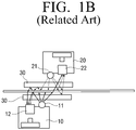
- FIGS. 1A and 1B are views illustrating problems of a related art.
- a scanner which can scan both sides of a sheet of paper on a paper path is disposed to reduce an increase in a scan speed and apparatus complexity of a double-sided structure.
- An original image is transferred using the paper path so that front and back sides of the original image, i.e., both sides, are simultaneously scanned through only one-time original image transfer.
- scan modules 10, 20 receive a signal from a scan module controller to operate according to the signal and controls devices necessary for reading an image, such as an image sensor, an analog front-end (AFE), etc.
- AFE analog front-end
- the scan modules 10, 20 are disposed close to one another to improve operation efficiency of a double-sided scan system. Therefore, a back side of an original image is shown due to crosstalk of illuminators 11, 21 of the scan modules 10, 20.
- two image sensor modules 12, 22 are disposed adjacent to each other and thus simultaneously operate. Therefore, a back side of an original image is projected and scanned on a reading image sensor 12 by an illuminator 21 of a counterpart image sensor 22.
- the two scan modules 10, 20 image reading modules
- a movement section of a paper sheet is reduced, thereby increasing the scan speed and minimizing an instrumental size of a scanner. Also, it is easy to secure a length of a planar section 30 required to prevent shaking of the paper sheet in an image reading section.
- JP H9 321947 A , WO 2012/013499 A1 and JP 2001 339576 A each disclose image reading apparatuses that alternately illuminate first and second sensors.
- EP 1202551 A2 discloses an image reading apparatus that illuminates first and second sensors with different timing and at different intensities, but does not alternately illuminate the two sensors.
- One or more exemplary embodiments may overcome the above disadvantages.
- One or more exemplary embodiments provide an image reading apparatus which can control illuminators of scan modules and a controlling method thereof.
- an image reading apparatus supporting a both-side scan mode.
- the image reading apparatus may include: an automatic paper transfer unit which automatically transfers a papers; a first scanning unit which includes a first light source and scans a first side of the paper; a second scanning unit which includes a second light source and scans a second side of the paper; and a controller which controls the first and second light sources to be alternately lit on a plurality of times within a cycle of a preset signal when the paper is transferred to the automatic paper transfer unit.
- the first and second scanning units may respectively further include image sensors which convert optical signal obtained by reading the paper into electric signals, wherein the controller controls the first and second light sources to be alternately lit on a plurality of times for one cycle of a line time of the image sensors.
- the controller may control the first and second light sources to be alternately lit on for a scan sub-direction cycle of the first and second scanning units.
- the controller may control the first and second light sources to be lit on the different numbers of times for one cycle of the preset signal.
- the controller may control the first and second light sources so that lighting duties of the first and second light sources are different from each other for one cycle of the preset signal.
- the controller may control the first and second light sources to be repeatedly lit on for a preset time within one cycle of the preset signal.
- the controller may control the first and second light sources to be repeatedly lit off for a preset time within one cycle of the preset signal.
- the controller may control alternate lighting cycles of the first and second light sources according to a distance cycle signal which depends on at least one of a motor cycle signal of the first and second scanning units, a line cycle signal of sub-scan direction image data, a scan sub-direction resolution, and a scan speed.
- the image reading apparatus may further include: a first sensor unit which is installed in a paper entering area of the automatic paper transfer unit; and a second sensor unit which is installed in a paper discharging area of the automatic paper transfer unit, wherein the controller controls the first and second light sources to be alternately lit on based on sensing results of the first and second sensor units.
- the controller may control light amounts of the first and second light sources in the alternate lighting to be different from each other and controls a scanned image to be compensated according to the adjusted light amounts.
- a method for controlling an image reading apparatus which supports a both-side scan mode and includes an automatic paper transfer unit which automatically transfers a paper, a first scanning unit which includes a first light source and scans a first side of the paper, a second scanning unit which includes a second light source and scans a second side of the paper and.
- the method may include: receiving a user command for both-side scanning; and alternately lighting on the first and second light sources a plurality of times for one cycle of a preset signal when the paper is transferred to the automatic paper transfer unit according to the user command.
- the first and second scanning units may respectively further include image sensors which convert optical signal obtained by reading the paper into electric signals, wherein the first and second light sources are alternately lit on a plurality of times for one cycle of a line time of the image sensors.
- the first and second light sources may be alternately lit on a plurality of times for a scan sub-direction cycle of the first and second scanning units.
- the first and second light sources may be lit on the different numbers of times for one cycle of the preset signal.
- the first and second light sources may be alternately lit on a plurality of times so that lighting duties of the first and second light sources are different from each other for one cycle of the preset signal.
- the first and second light sources may be repeatedly lit on for a preset time within one cycle of the preset signal.
- the first and second light sources may be repeatedly lit off for a preset time within one cycle of the preset signal.
- Alternate lighting cycles of the first and second light sources may be controlled according to a distance cycle signal which depends on at least one of a motor cycle signal of the first and second scanning units, a line cycle signal of sub-scan direction image data, a scan sub-direction resolution, and a scan speed.
- the image reading apparatus further include: a first sensor unit which is installed in a paper entering area of the automatic paper transfer unit; and a second sensor unit which is installed in a paper discharging area of the automatic paper transfer unit, wherein the first and second light sources are alternately lit on based on sensing results of the first and second sensor units.
- the method may further include controlling light amounts of the first and second light sources in the alternate lighting to be different from each other and controlling a scanned image to be compensated according to the adjusted light amounts.
- FIGS. 2A and 2B are block diagrams illustrating structures of image reading apparatuses according to various exemplary embodiments.
- an image reading apparatus 100 includes a first scanning unit 110, a second scanning unit 120, an automatic paper transfer unit 130, and a controller 140.
- the image reading apparatus 100 is an apparatus which scans light to read an image recorded on a paper.
- the image reading apparatus 100 may be installed in an image forming apparatus such as a copier, a printer, a fax machine, or a multifunction peripheral (MFP) which complexly realizes functions of them through one device.
- an image forming apparatus such as a copier, a printer, a fax machine, or a multifunction peripheral (MFP) which complexly realizes functions of them through one device.
- MFP multifunction peripheral
- the first scanning unit 110 which scans a first side of the paper and the second scanning unit 120 which scans a second side of the paper are installed to face each other in order to scan both sides of the paper, i.e., the first and second sides.
- this method has an advantage in that both sides of a paper are nearly simultaneously scanned without necessarily circulating the paper to enable high-speed both-side scanning.
- the first scanning unit 110 scans the first side of the paper and may include a first light source which scans light onto the paper.
- the second scanning unit 120 scans the second side of the paper and may include a second light source which scans light onto the paper.
- the first and second scanning units 110 and 120 may be realized as scanning modules which scan light onto the paper through their light sources, read a visible image printed on the paper as an optical signal, convert the optical signal into an electric signal, and provide the electric signal to a signal processing module (not shown).
- the light sources may be realized as lamps, such as compact fluorescent lamps (CFLs) or Xe-Lamps, light-emitting diodes (LEDs), or the like.
- lamps such as compact fluorescent lamps (CFLs) or Xe-Lamps, light-emitting diodes (LEDs), or the like.
- the automatic paper transfer unit 130 automatically transfers the paper and may be realized as an automatic document feeder (ADF).
- ADF automatic document feeder
- the controller 140 controls the first and second light sources of the first and second scanning units 110 and 120 to be alternately lighted on at least one time when the paper is transferred to the automatic paper transfer unit 130 in both-side scanning.
- the controller 140 controls the first and second light sources to be alternately lighted on a plurality of times within one preset signal cycle.
- the controller 140 may control the first and second light sources to be lighted on different times for the preset signal cycle.
- the controller 140 controls the first and second light sources so that lighting duties of the first and second light sources are different from each other for the preset signal cycle.
- the controller 140 controls the first and second light sources to be repeatedly lit for the preset one signal cycle
- the controller 140 controls the first and second light sources to be repeatedly switched off for the preset one signal cycle.
- the first and second scanning units 110 and 120 respectively include first and second image sensors (not shown) which read the visible image printed on the paper, which is transferred through the automatic transfer unit 130, to acquire the optical signal and convert the optical signal into the electric signal.
- first and second image sensors (not shown) which read the visible image printed on the paper, which is transferred through the automatic transfer unit 130, to acquire the optical signal and convert the optical signal into the electric signal.
- charge-coupled devices CCDs
- contact image sensors CISs
- the controller 140 controls the first and second light sources to be lit a plurality of times for one line time of the first and second image sensors.
- the controller 140 synchronizes alternate lighting cycles of the first and second light sources with light time signals of the first and second image sensors.
- the controller 140 controls the alternate lighting cycles of the first and second light sources according to a pulse width modulation (PWM) signal.
- PWM pulse width modulation
- the controller 140 heightens a frequency of a PWM pulse to reduce a light deviation if the alternate lighting signal does not synchronize with the light time signals of the first and second image sensors.
- the controller 140 changes the frequency and duty of the PWM pulse to minimize the light deviation.
- the controller 140 controls the first and second light sources to be alternately lit at least one time for one cycle of scan sub-direction signals of the first and second scanning units 110 and 120.
- the controller 140 synchronizes the alternate lighting cycles of the first and second light sources with the scan sub-direction cycle signals.
- the controller 140 controls the first and second light sources to be alternately lit according to at least one of a motor cycle signal of the first and second scanning units 110 and 120, a cycle signal of each line of sub-scan direction image data, and a distance cycle signal according to at least one of a scan sub-direction resolution and a scan speed.
- FIG. 2B is a block diagram illustrating a structure of an image reading apparatus 200 according to another exemplary embodiment.
- the image reading apparatus 200 includes a first scanning unit 210, a second scanning unit 220, an automatic paper transfer unit 230, a controller 240, a first sensor unit 250, and a second sensor unit 260.
- a first scanning unit 210 the image reading apparatus 200 includes a first scanning unit 210, a second scanning unit 220, an automatic paper transfer unit 230, a controller 240, a first sensor unit 250, and a second sensor unit 260.
- the first sensor unit 250 is installed in a paper entering area of the first scanning unit 210 to sense a transfer of a paper.
- the second sensor unit 260 is installed in a paper discharge area of the second scanning unit 220 to sense a discharge of the paper.
- the controller 240 controls a first light source to start alternate lighting and controls a second light source to start alternate lighting after a preset time elapses.
- the controller 240 controls the first and second light sources to stop the alternate lightings of the first and second light sources and to be lit off.
- At least one third sensor unit may be installed between the first and second sensor units 250 and 260.
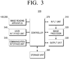
- FIG. 3 is a block diagram illustrating a structure of an image forming apparatus 300 according to an exemplary embodiment.
- the image forming apparatus 300 includes the image reading apparatus 100 or 200 shown in FIG. 2A or 2B , an input unit 310, a rendering unit (not shown), an image processor 320, an output unit 330, a user interface unit 340, a communication interface unit 350, a storage unit 360, and a controller 370.
- the image forming apparatus 300 is connected to an external device and outputs document data.
- the image forming apparatus 300 may be realized as various types such as a printer, a scanner, a copier, a fax machine, a MFP which has at least two or more of functions of the printer, the scanner, the copier, and the fax machine, etc.
- a structure of the image reading apparatus 100 or 200 is as described with reference to FIGS. 2A and 2B , and thus its detailed descriptions will be omitted herein.
- the input unit 310 receives image data which is to be image-processed.
- the input unit 310 receives or generates a printed image or a scanned image.
- the input unit 310 may receive an image which is generated through an application program or a driver included in a host device (not shown) or a RGB rendering image which is generated through an emulation.
- the input unit 310 may receive an image which is scanned by an RGB sensor.
- the rendering unit (not shown) converts the image data input through the input unit 310 into bitmap data of an RGB space.
- the image processor 320 performs image processing with respect to input data under control of the controller 370.
- the image processor 320 converts each RGB 8-bit image of each channel into an CMYK color image through a color conversion, improves an image quality of the CMYK color image, and generates the CMYK color image as a-bit image (binary data) through halftoning.
- the output unit 330 prints data, which has been image-processed by the image processor 320, on a recording medium and outputs the data under control of the controller 370.
- the output unit 330 prints an image according to a signal input from the image reading apparatus 100 or 200 or a signal input from an external device such as a personal computer (PC) or the like.
- the output unit 330 may include a feeding unit which feeds a paper that is a printing medium, a developing unit which develops an image on the paper, a fixing unit which fixes the image, which is developed by applying heat and pressure to the paper, on the paper, and a paper discharging unit which discharges the paper, on which printing has been completed, to the outside.
- papers loaded in a paper tray are transferred through a pickup roller to the developing unit.
- An electrostatic latent image is formed on a surface of a photoreceptor, which is charged with predetermined potential by a charging roller, by an exposing unit.
- the electrostatic latent image is developed as a toner image by a developing roller and then transferred to the paper by a transfer roller.
- the toner image transferred to the paper passes between a heating roller and a pressurizing roller of the fixing unit and thus is fixed on the paper due to heat and pressure.
- the paper which has passed through the fixing unit is transferred by paper discharging rollers and then discharged to the outside.
- the user interface unit 340 includes a controlling key (not shown) through which a user command to control an operation of the image forming apparatus 300 is input and a display window (not sown), such as a liquid crystal display (LCD), which displays a state of the image forming apparatus 300.
- a controlling key not shown
- a display window not sown
- LCD liquid crystal display
- the user interface unit 340 may be realized as a unit which simultaneously realizes an input and an output such as a touch pad or the like.
- the user interface unit 340 displays various types of information provided from the image forming apparatus 300, a progress state of a job progressing in the image forming apparatus 300, and a result of the job.
- a user checks, manages, and controls various types of printing jobs of the image forming apparatus 300 through the user interface unit 340
- the communication interface unit 350 supports data communication which is performed with an external (not shown) through a network.
- the communication interface unit 350 may be realized as a form which supports a digital living network alliance (DLNA) network, a local method, a local area network (LAN), an Internet, or the like.
- DLNA digital living network alliance
- the communication interface unit 350 receives an image which is generated through an application program or a driver of a host device (not shown) or an RGB rendering image which is generated through an emulation and provides the received image to the input unit 310.
- the input unit 310 and the communication interface unit 350 are illustrated as separate structures in FIG. 3 . This is only an exemplary embodiment, and thus the communication interface unit 350 may be realized as the input unit 310.
- the storage unit 360 may be realized as a storage medium of the image forming apparatus 300 or an external storage medium.
- the storage unit 360 may be realized as a removable disk including a universal serial bus (USB) memory, a storage medium connected to a host, a web server connected through a network, or the like.
- USB universal serial bus
- the controller 370 controls operations of elements of the image forming apparatus 300 according to pre-stored various types of programs.
- the controller 370 controls operations of the input unit 310, the image processor 320, the output unit 330, the user interface unit 340, the communication interface unit 350, and the storage unit 360.
- FIG. 4 is a view illustrating an operation of the image reading apparatus 200 of FIG. 2B , according to an exemplary embodiment.
- interference between illuminators 211 and 221 of scan modules 210 and 220 (the first and second scanning units described above) occurring during both-side scanning is reduced.
- the first and second light sources 211 and 221 of the scan modules 210 and 220 are controlled to remove or reduce the interference between the illuminators 211 and 221.
- the two sensors 250 and 260 adhere on a paper transfer path of the automatic paper transfer unit 230 to check a feeding state of the paper.
- the two sensors 240 transmit a feeding state signal of the paper to the controller 240, and the controller 240 controls the illuminators 211 and 221 using the feeding state signal.
- the controller 240 may be realized as a scan module controller.
- lighting states of the illuminators may be controlled as shown in Table 1 below.
- Table 1 First Sensor (S1) Second Sensor Lighting States of Illuminators OFF OFF Light off First and Second Scan Module ON OFF Alternately Light on First and Second Scan Modules ON ON Alternately Light on First and Second Scan Modules OFF ON Alternately Light on First and Second Scan Modules OFF OFF Light off First and Second Scan Modules
- the paper is fed to the first scanning unit 210 by the first sensor 250 which senses a feeding state of the paper. This signal is transmitted to the controller 240, and the illuminators 211 and 221 of the first and second scan modules 210 and 220 start to be alternately lit on through the controller 240.
- the lighting states of the illuminators may be controlled as shown in Table 2 below.
- Table 2 First Sensor (S1) Second Sensor (S2) Lighting States of Illuminators OFF OFF Light off First and Second Scan Modules ON OFF Alternately Light on First and Second Scan Modules ON ON Alternately Light on First and Second Scan Modules OFF ON Alternately Light on Second Scan Module OFF OFF Light off First and Second Scan Modules
- the first and second sensors S1 and S2 are turned on when the illuminators are alternately lit on, the first light source of the first scan module 210 is first lit off.
- the lighting states of the illuminators may be controlled as shown in Table 3 above.
- first and second sensors S1 and S2 are turned off when the illuminators are alternately lit on as shown in Table 3 above, the first light source of the first scan module 210 is first lit on, and then the second light source of the second scan module 220 is lit on after a predetermined time. In more detail, the second light source of the second scan module 220 is lit on after a time corresponding to a distance D1 shown in FIG. 4 .
- the lighting states of the illuminators may be controlled as shown in Table 4 below.
- Table 4 First Sensor (S1) Second Sensor(S2) Lighting States of Illuminators OFF OFF Light off First and Second Scan Modules ON OFF Light on First Scan Module, and then Light on Second Scan Module after Predetermined Time ON ON Alternately Light on First and Second Scan Module OFF ON Alternately Light on First and Second Scan Modules OFF OFF Light off First and Second Scan Modules
- times when alternate lighting starts and ends may be adjusted according to the number and positions of paper sensors.
- FIG. 5 is a view illustrating a method for controlling alternate lighting according to an exemplary embodiment.
- first and second scan modules 210 and 220 synchronize with each other according to a preset signal. Also, the first and second scan modules 210 and 220 are alternately lit at least one or more times for a cycle of the preset signal.
- a sync signal may be at least one of line times, shutter times, and scan sub-direction cycle signals of light-receiving units of the first and second scan modules, i.e., image sensors 212 and 222.
- the scan sub-direction cycle signals may include at least one of motor cycle signals of the first and second scan modules 210 and 220, a line cycle signal of sub-scan direction image data, a scan sub-direction resolution, and a distance cycle signal which depends on a scan speed.
- the controller 240 controls the first and second scan modules 210 and 220 so that a constant time interval occurs between on times of illuminators of the first and second scan modules 210 and 220. In other words, since the first and second scan modules 210 and 220 require different light amounts, the illuminators may be lit on for an appropriate time.
- the illuminators of the first and second scan modules 210 and 220 may be lit off only for 20% time of one-time cycle.
- This time may be a time difference between the first and second scan modules 210 and 220.
- the time may be adjusted to 90% of maximum spec at which light amounts of light-receiving units are saturated, to improve an image-quality.
- the first and second scan modules 210 and 220 may extend to be lit on a plurality of times within an alternate cycle.
- a preset signal is a scan sub-direction signal
- the preset signal may be controlled by a method of using 600dpi and 300dpi in scanning.
- a distance of scan sub-direction varies during 600dpi and 300dpi operations.
- an alternate lighting time may be adjusted to this time. Therefore, a distance depending on at least one of a scan direction resolution and a scan speed may be made and used as a table. For example, in the case of 300dpi and 600dpi, the distance may be set to a multiple relation to be simply controlled.
- first and second scan modules may be alternately lit on so that light of the second scan module does not go into the first scan module or an opposite direction. Therefore, an image deterioration, such as back side showing or the like, does not occur, and a clear image quality may be obtained through a light source control.
- FIG. 6 is a view illustrating a method for radiating light in both-side scanning according to an exemplary embodiment.
- a light amount of a first light source 111 is radiated onto a first sensor 112 to read image data
- a light amount of a second light source 121 is radiated onto a second sensor 122 to read image data.
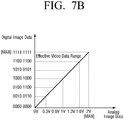
- FIGS. 7A and 7B are views illustrating an image data conversion process according to an exemplary embodiment.
- ADC analog-to-digital converter
- the ADC limits voltage ranges of the analog image data, which are input conditions, to convert the analog data into the digital codes.
- analog image data is converted into digital image data within a constant range of the analog image data. Since other areas are values which cannot be expressed by the ADC, a scan module converts the analog image data into the digital codes within a limit of the analog image data.
- image data is expressed within a range between 0V and 2V to express an image using 2 8 (256) level, thereby normally expressing the image. Therefore, if the image data is expressed within a range between 0V and 3V, the image is not expressed well.
- a light-receiving unit such as a charge-coupled device (CCD). If a maximum light amount exceeds a limit of a range as shown in Table 5 below, a light amount of the light source is controlled to adjust luminance thereof not to exceed the limit.
- analog image data which is a final output of each scan module. If analog image data exceeds a full (max) range spec, an image is not expressed. If the analog image data does not exceed the full range spec, the image is not expressed. Therefore, a maximum amount of the analog image data may be adjusted to 90% of a maximum amount.
- the maximum amount of the analog image data is as shown in Table 5 below.
- Table 5 Scan Module 1 Scan Module 2 CCD Sensitivity 10V/lx.s 8V/lx.s Light Source Luminance 2500lux 3500lux Analog Image Data (Full Range) 2.1V 2.3V Analog Image Data (Light Source On/Off Control) 1.8V 1.8V
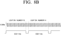
- Alternate lighting is performed a plurality of times within a line time cycle of the CCD to reduce tolerance of a light amount, thereby reducing tolerance of an image.
- a deviation of a light amount is 12.5% (100 x (8-7)/8)) within each line time.
- a deviation of a light amount is 6.6% (100x15-14)/15) within each line time. Therefore, as the light amount is quickly on/off, the deviation of the light amount is reduced.
- the light amount affects an image quality. Therefore, noise of 12.5% occurs in a video image in FIG. 8A , and noise of 6.6% occurs in the video image in FIG. 8B .
- lighting may be alternately performed a plurality of times within a cycle of a line time signal of an image sensor of a light-receiving unit to make image data clear.
- a lamp such as a CCFL or an Xe-lamp, may operate within a range between 50 Khz and 100 Khz, and an LED may operate at 200 Khz or less in consideration of an LED driver and an LED switching response.
- a light source is adjusted to specific frequency of 200 Khz in consideration of a response time thereof. Also, a sensor output level is checked to check whether an appropriate light amount is output, using pre-processing for image correction such as shading correction to search for a further accurate frequency, thereby controlling a frequency and a cycle.
- alternate lighting is set (S910).
- a scan controller sets a light source control signal as an operation signal of 200 Khz to light on/off a light source signal (S920).
- An LED is repeatedly lit on/off at 200 Khz to read a shading level patch (S930). Whether there is an abnormality in a shading data level is checked (S940).
- the shading data level is re-checked to search for and set a normal value.
- the normal value may be set to lower a frequency and increase an on-duty time of duty.
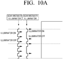
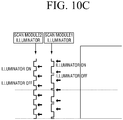
- FIGS. 10A through 10C are views illustrating alternate lighting according to various exemplary embodiments.
- first and second modules are controlled to be lit on different times in alternate lighting.
- an illuminator of the first scan module scanning a first side of a paper is lit on and then is lit off after a predetermined time.
- An illuminator of the second scan module is lit on after a predetermined time.
- alternate lightings synchronize with each other according to a preset signal, and the number of lightings of the illuminator of the first scan module and the number of lightings of the illuminator of the second scan module are set to be different from each other within a cycle of the present signal.
- the preset signal may be at least one of a line time (shutter time) signal and a scan sub-direction cycle signal of the above-described light-receiving unit.
- an illuminator of a first scan module scanning a first side of a paper is lit on and the lit off after a predetermined time
- an illuminator of a second scan module is lit on after a predetermined time.
- the preset signal may be at least one of a line time (shutter time) signal and a scan sub-direction cycle signal of the above light-receiving unit.
- an illuminator of a first scan module scanning a first side of a paper is lit on and then is lit off after a predetermined time, and an illuminator of a second scan module is lit on after a predetermined time.
- These alternate lightings synchronize with each other according to a specific signal.
- the illuminators of the first and second scan modules are alternately lit on with a cycle of the specific signal. If an image effect according to illuminator interference is lower, alternating lighting times of the illuminators overlaps with each other.
- interference may be set to about 1%, and interference of a paper having simple texts may be set to 10% or less.
- not alternate lighting but light of an illuminator of a scan module is slightly radiated so that back side showing does not affect an image.
- a light source is adjusted as described above, and a gain factor of image data is automatically changed by an adjusted amount of light of the light source.
- a PGA factor of an FE is adjusted or light is added to image data by a reduced amount.
- a ratio of shading data stored in a memory may be adjusted by the reduced amount to adjust input image data, thereby making an image quality further clear.
- image data is compensated by a reduced intensity of light so that back side showing does not occur.
- the image data since an amount of light and image data are directly proportional to each other, the image data may be increased two times if the amount of light is reduced to 50%.
- FIG. 11 is a flowchart illustrating a scanning method according to an exemplary embodiment.
- a scan controller reduces the intensity of the light source of the scan module (S1110). Then, it is determined if a back side of the paper is showing (S1120). If the back side is showing (S1120:Y) then intensity of the light source is further reduced (S1130). Subsequently, it is determined if the image quality is clear (S1140). If the image quality is clear (S1140:Y), the a scanning operation is performed (S1150). If the image quality is not clear (S1140:N) the image is compensated (S1160) and the method returns to Operation S1130.
- S1170 If the back side is not showing (S1120:N) then it is determined if the image quality is clear (S1170). If the image quality is clear (S1170:Y), the a scanning operation is performed (S1150). If the image quality is not clear (S1170:N) the image is compensated (S1180) and the method returns to Operation S1170.
- an image quality clearness determining block may be omitted. This is because an amount of light and image data are directly proportional to each other, and a reduced amount of the light can be checked in advance.
- An image quality clearness determination is performed by reading a specific pattern using a scan module and comparing a value of the specific pattern with an original value. In other words, a part of the specific pattern is read to reduce an image quality clearness determination time of operations of FIG. 11 . Also, back side showing may be determined using this.
- thermometer and a temperature measurer which measure temperature temperate of parts around of light sources of scan modules are installed to check lighting states of the scan modules in alternate lighting. Therefore, lighting states are checked using measured temperatures to be used in the alternate lighting.
Landscapes
- Engineering & Computer Science (AREA)
- Multimedia (AREA)
- Signal Processing (AREA)
- Health & Medical Sciences (AREA)
- Biomedical Technology (AREA)
- General Health & Medical Sciences (AREA)
- Facsimile Scanning Arrangements (AREA)
- Image Input (AREA)
Claims (13)
- Bildlesevorrichtung, die einen beidseitigen Abtastmodus unterstützt, wobei die Bildlesevorrichtung Folgendes umfasst:eine automatische Papiertransporteinheit (130), die automatisch ein Papier transportiert,eine erste Abtasteinheit (110), die eine erste Lichtquelle umfasst und eine erste Seite des Papiers abtastet,eine zweite Abtasteinheit (120), die eine zweite Lichtquelle umfasst und eine zweite Seite des Papiers abtastet,eine Steuerung (140), welche die erste und die zweite Lichtquelle (110, 120) so steuert, dass sie abwechselnd mehrere Male innerhalb eines Zyklus eines voreingestellten Signals erleuchtet werden, wenn das Papier durch die automatische Papiertransporteinheit (130) transportiert wird,wobei der Zyklus des voreingestellten Signals mit wenigstens einem Zeilenzeitsignal von Bildsensoren und/oder einem Abtast-Unterrichtungssignal von der ersten und der zweiten Abtasteinheit synchronisiert ist,wobei die Steuerung die erste und die zweite Lichtquelle so steuert, dass sie für einen Zyklus des voreingestellten Signals unterschiedliche Anzahlen von Malen erleuchtet werden, oder die erste und die zweite Lichtquelle so steuert, dass sich Beleuchtungseinschaltdauern der ersten und der zweiten Lichtquelle für einen Zyklus des voreingestellten Signals voneinander unterscheiden.
- Bildlesevorrichtung nach Anspruch 1, wobei die erste und die zweite Abtasteinheit jeweils ferner Bildsensoren umfassen, die ein durch Lesen des Papiers erhaltenes optisches Signal in elektrische Signale umwandeln,
wobei die Steuerung die erste und die zweite Lichtquelle so steuert, dass sie für einen Zyklus einer Zeilenzeit der Bildsensoren abwechselnd mehrere Male erleuchtet werden. - Bildlesevorrichtung nach Anspruch 1 oder 2, wobei die Steuerung die erste und die zweite Lichtquelle so steuert, dass sie für einen Abtast-Unterrichtungszyklus der ersten und der zweiten Abtasteinheit abwechselnd erleuchtet werden.
- Bildlesevorrichtung nach einem der Ansprüche 1 bis 3, wobei die Steuerung die erste und die zweite Lichtquelle so steuert, dass sie wiederholt für eine voreingestellte Zeit innerhalb eines Zyklus des voreingestellten Signals erleuchtet oder ausgeschaltet werden.
- Bildlesevorrichtung nach Anspruch 3, wobei die Steuerung abwechselnde Beleuchtungszyklen der ersten und der zweiten Lichtquelle entsprechend einem Entfernungszyklussignal steuert, das von wenigstens einem Motorzyklussignal der ersten und der zweiten Abtasteinheit, einem Zeilenzyklussignal von Unterabtastrichtung-Bilddaten, einer Abtast-Unterrichtungsauflösung und/oder einer Abtastgeschwindigkeit abhängt.
- Bildlesevorrichtung nach einem der Ansprüche 1 bis 5, die ferner Folgendes umfasst:eine erste Sensoreinheit, die in einem Papiereintrittsbereich der automatischen Papiertransporteinheit eingebaut ist, undeine zweite Sensoreinheit, die in einem Papierausgabebereich der automatischen Papiertransporteinheit eingebaut ist,wobei die Steuerung die erste und die zweite Lichtquelle so steuert, dass sie auf Grundlage von Erfassungsergebnissen der ersten und der zweiten Sensoreinheit abwechselnd erleuchtet werden.
- Bildlesevorrichtung nach einem der Ansprüche 1 bis 6, wobei die Steuerung Lichtmengen der ersten und der zweiten Lichtquelle bei der abwechselnden Beleuchtung so steuert, dass sie sich voneinander unterscheiden, und ein abgetastetes Bild so steuert, dass es entsprechend den eingestellten Lichtmengen ausgeglichen wird.
- Verfahren zum Steuern einer Bildlesevorrichtung, die einen beidseitigen Abtastmodus unterstützt und eine automatische Papiertransporteinheit (130), die automatisch ein Papier transportiert, eine erste Abtasteinheit (110), die eine erste Lichtquelle umfasst und eine erste Seite des Papiers abtastet, und eine zweite Abtasteinheit (120), die eine zweite Lichtquelle umfasst und eine zweite Seite des Papiers abtastet, umfasst, wobei das Verfahren Folgendes umfasst:Empfangen eines Benutzerbefehls zum beidseitigen Abtasten undabwechselndes Beleuchten an der ersten und der zweiten Lichtquelle mehrere Male für einen Zyklus eines voreingestellten Signals, wenn das Papier durch die automatische Papiertransporteinheit (130) entsprechend dem Benutzerbefehl transportiert wird,wobei der Zyklus des voreingestellten Signals mit wenigstens einem Zeilenzeitsignal von Bildsensoren und/oder einem Abtast-Unterrichtungssignal von der ersten und der zweiten Abtasteinheit synchronisiert wird,
wobei die erste und die zweite Lichtquelle für einen Zyklus des voreingestellten Signals die unterschiedlichen Anzahlen von Malen erleuchtet werden oder die erste und die zweite Lichtquelle abwechselnd mehrere Male erleuchtet werden, so dass sich Beleuchtungseinschaltdauern der ersten und der zweiten Lichtquelle für einen Zyklus des voreingestellten Signals voneinander unterscheiden. - Verfahren nach Anspruch 8, wobei die erste und die zweite Abtasteinheit jeweils ferner Bildsensoren umfassen, die ein durch Lesen des Papiers erhaltenes optisches Signal in elektrische Signale umwandeln,
wobei die erste und die zweite Lichtquelle für einen Zyklus einer Zeilenzeit der Bildsensoren abwechselnd mehrere Male erleuchtet werden. - Verfahren nach Anspruch 8 oder 9, wobei die erste und die zweite Lichtquelle für einen Abtast-Unterrichtungszyklus der ersten und der zweiten Abtasteinheit abwechselnd erleuchtet werden.
- Verfahren nach einem der Ansprüche 8 bis 10, wobei die erste und die zweite Lichtquelle wiederholt für eine voreingestellte Zeit innerhalb eines Zyklus des voreingestellten Signals erleuchtet oder ausgeschaltet werden.
- Verfahren nach einem der Ansprüche 8 bis 11, wobei die erste und die zweite Lichtquelle wiederholt für eine voreingestellte Zeit innerhalb eines Zyklus des voreingestellten Signals erleuchtet werden.
- Verfahren nach einem der Ansprüche 8 bis 12, wobei abwechselnde Beleuchtungszyklen der ersten und der zweiten Lichtquelle entsprechend einem Entfernungszyklussignal gesteuert werden, das von wenigstens einem Motorzyklussignal der ersten und der zweiten Abtasteinheit, einem Zeilenzyklussignal von Unterabtastrichtung-Bilddaten, einer Abtast-Unterrichtungsauflösung und/oder einer Abtastgeschwindigkeit abhängt.
Applications Claiming Priority (1)
| Application Number | Priority Date | Filing Date | Title |
|---|---|---|---|
| KR1020110000562A KR20120079333A (ko) | 2011-01-04 | 2011-01-04 | 화상독취장치 및 그 제어 방법 |
Publications (3)
| Publication Number | Publication Date |
|---|---|
| EP2472844A2 EP2472844A2 (de) | 2012-07-04 |
| EP2472844A3 EP2472844A3 (de) | 2012-10-24 |
| EP2472844B1 true EP2472844B1 (de) | 2019-03-06 |
Family
ID=45524268
Family Applications (1)
| Application Number | Title | Priority Date | Filing Date |
|---|---|---|---|
| EP11195522.5A Not-in-force EP2472844B1 (de) | 2011-01-04 | 2011-12-23 | Bildlesevorrichtung und Steuerverfahren dafür |
Country Status (4)
| Country | Link |
|---|---|
| US (1) | US8804207B2 (de) |
| EP (1) | EP2472844B1 (de) |
| JP (1) | JP2012142948A (de) |
| KR (1) | KR20120079333A (de) |
Families Citing this family (12)
| Publication number | Priority date | Publication date | Assignee | Title |
|---|---|---|---|---|
| EP2067119A2 (de) * | 2006-09-08 | 2009-06-10 | Exbiblio B.V. | Optische scanner, zum beispiel tragbare optische scanner |
| JP5380563B2 (ja) * | 2012-02-24 | 2014-01-08 | 京セラドキュメントソリューションズ株式会社 | 画像読取装置及びこれを備えた画像形成装置 |
| JP6080541B2 (ja) * | 2012-12-26 | 2017-02-15 | 日本放送協会 | 立体画像取得装置および立体画像取得方法 |
| JP5777649B2 (ja) * | 2013-01-28 | 2015-09-09 | 京セラドキュメントソリューションズ株式会社 | 情報処理装置 |
| JP5921511B2 (ja) * | 2013-09-30 | 2016-05-24 | 富士フイルム株式会社 | 放射線画像読取装置、放射線画像読取プログラム、及び放射線画像読取方法 |
| JP6179436B2 (ja) * | 2014-03-28 | 2017-08-16 | ブラザー工業株式会社 | 画像読取装置 |
| JP6439290B2 (ja) * | 2014-06-25 | 2018-12-19 | 富士ゼロックス株式会社 | 画像読取装置及びプログラム |
| JP6464586B2 (ja) * | 2014-07-14 | 2019-02-06 | ブラザー工業株式会社 | 画像読取装置 |
| KR20170040997A (ko) * | 2015-10-06 | 2017-04-14 | 에스프린팅솔루션 주식회사 | 화상 획득 장치, 화상 획득 방법 및 화상 형성 장치 |
| JP6745602B2 (ja) * | 2016-02-15 | 2020-08-26 | キヤノン株式会社 | 画像読取装置およびその制御方法 |
| JP6992324B2 (ja) * | 2017-08-25 | 2022-01-13 | 京セラドキュメントソリューションズ株式会社 | 画像読取装置及び画像読取装置を備えた画像形成装置 |
| US11689678B2 (en) * | 2021-07-06 | 2023-06-27 | Anhui Gaozhe Information Technology Co., Ltd | Double-sided synchronous scanning device and double-sided synchronous scanner |
Citations (1)
| Publication number | Priority date | Publication date | Assignee | Title |
|---|---|---|---|---|
| JP2001339576A (ja) * | 2000-05-26 | 2001-12-07 | Canon Inc | 両面読取り型画像読取り装置及び該装置の制御方法 |
Family Cites Families (5)
| Publication number | Priority date | Publication date | Assignee | Title |
|---|---|---|---|---|
| JPH0290862A (ja) * | 1988-09-28 | 1990-03-30 | Eastman Kodatsuku Japan Kk | 情報読み取り装置 |
| JPH09321947A (ja) * | 1996-05-29 | 1997-12-12 | Ricoh Co Ltd | 画像読取り装置 |
| JP2002111977A (ja) | 2000-10-03 | 2002-04-12 | Nisca Corp | 画像読取装置及び画像読み取り方法 |
| JP3579644B2 (ja) | 2000-10-25 | 2004-10-20 | シャープ株式会社 | 両面原稿読取り装置及び画像形成装置 |
| FR2963527B1 (fr) | 2010-07-30 | 2013-05-24 | Sagemcom Documents Sas | Scanner recto verso d'un document, et procede de commande associe |
-
2011
- 2011-01-04 KR KR1020110000562A patent/KR20120079333A/ko active Application Filing
- 2011-09-23 US US13/200,368 patent/US8804207B2/en active Active
- 2011-12-23 EP EP11195522.5A patent/EP2472844B1/de not_active Not-in-force
-
2012
- 2012-01-04 JP JP2012000283A patent/JP2012142948A/ja active Pending
Patent Citations (1)
| Publication number | Priority date | Publication date | Assignee | Title |
|---|---|---|---|---|
| JP2001339576A (ja) * | 2000-05-26 | 2001-12-07 | Canon Inc | 両面読取り型画像読取り装置及び該装置の制御方法 |
Also Published As
| Publication number | Publication date |
|---|---|
| US8804207B2 (en) | 2014-08-12 |
| EP2472844A2 (de) | 2012-07-04 |
| JP2012142948A (ja) | 2012-07-26 |
| KR20120079333A (ko) | 2012-07-12 |
| US20120170083A1 (en) | 2012-07-05 |
| EP2472844A3 (de) | 2012-10-24 |
Similar Documents
| Publication | Publication Date | Title |
|---|---|---|
| EP2472844B1 (de) | Bildlesevorrichtung und Steuerverfahren dafür | |
| US20090207450A1 (en) | Image scanning apparatus, shading correction method, and shading correction program | |
| US9065949B2 (en) | Document reading device and image formation apparatus | |
| EP2548367B1 (de) | Bildleser und bilderzeugungsvorrichtung | |
| US20150156374A1 (en) | Image reading apparatus, image reading method and a program for measuring black and white reference data | |
| US11290669B2 (en) | Image reading apparatus and image forming apparatus | |
| US20090316172A1 (en) | Image reading apparatus and image forming apparatus | |
| TWI524727B (zh) | 影像讀取裝置,影像形成裝置及電腦可讀取之媒體 | |
| JP5533230B2 (ja) | 画像読取装置と画像形成装置 | |
| US8947753B2 (en) | Imaging device for an image reading apparatus, and image reading method | |
| JP7196582B2 (ja) | 読取装置、画像形成装置および読取方法 | |
| JP5244881B2 (ja) | 画像読取装置及び画像形成装置 | |
| US20190121268A1 (en) | Image forming apparatus | |
| US8456678B2 (en) | Image reading apparatus and image reading method | |
| US7542179B2 (en) | Image reading method, image reading apparatus, and image forming apparatus | |
| US7592574B2 (en) | Light source control apparatus, image reading apparatus, image forming apparatus, medium storing light source part control program, and method for controlling of light source part by adjusting light quantity ratios | |
| KR101846935B1 (ko) | 화상독취장치 및 그 제어 방법 | |
| US7408682B2 (en) | Image reading apparatus | |
| JP5842625B2 (ja) | 原稿読取装置及び画像形成装置と原稿読取方法 | |
| JP2012070097A (ja) | 原稿読み取り装置 | |
| JP5743875B2 (ja) | 画像読取装置、画像形成装置、画像読取方法 | |
| JP4928597B2 (ja) | 画像読取装置、画像処理装置、及び画像形成装置、そのシステム及びその制御方法 | |
| JP2002281240A (ja) | 画像読み取り装置 | |
| JP2008167039A (ja) | 画像処理装置、画像形成装置及び画像読取装置 | |
| JP2012151644A (ja) | 画像読取装置、画像読取装置を備えた画像形成装置及び画像処理方法 |
Legal Events
| Date | Code | Title | Description |
|---|---|---|---|
| AK | Designated contracting states |
Kind code of ref document: A2 Designated state(s): AL AT BE BG CH CY CZ DE DK EE ES FI FR GB GR HR HU IE IS IT LI LT LU LV MC MK MT NL NO PL PT RO RS SE SI SK SM TR |
|
| AX | Request for extension of the european patent |
Extension state: BA ME |
|
| PUAI | Public reference made under article 153(3) epc to a published international application that has entered the european phase |
Free format text: ORIGINAL CODE: 0009012 |
|
| RAP1 | Party data changed (applicant data changed or rights of an application transferred) |
Owner name: SAMSUNG ELECTRONICS CO., LTD. |
|
| PUAL | Search report despatched |
Free format text: ORIGINAL CODE: 0009013 |
|
| AK | Designated contracting states |
Kind code of ref document: A3 Designated state(s): AL AT BE BG CH CY CZ DE DK EE ES FI FR GB GR HR HU IE IS IT LI LT LU LV MC MK MT NL NO PL PT RO RS SE SI SK SM TR |
|
| AX | Request for extension of the european patent |
Extension state: BA ME |
|
| RIC1 | Information provided on ipc code assigned before grant |
Ipc: H04N 1/028 20060101ALI20120918BHEP Ipc: H04N 1/00 20060101ALI20120918BHEP Ipc: H04N 1/203 20060101AFI20120918BHEP |
|
| 17P | Request for examination filed |
Effective date: 20130418 |
|
| 17Q | First examination report despatched |
Effective date: 20150604 |
|
| RAP1 | Party data changed (applicant data changed or rights of an application transferred) |
Owner name: S-PRINTING SOLUTION CO., LTD. |
|
| STAA | Information on the status of an ep patent application or granted ep patent |
Free format text: STATUS: EXAMINATION IS IN PROGRESS |
|
| RAP1 | Party data changed (applicant data changed or rights of an application transferred) |
Owner name: HP PRINTING KOREA CO., LTD. |
|
| GRAP | Despatch of communication of intention to grant a patent |
Free format text: ORIGINAL CODE: EPIDOSNIGR1 |
|
| STAA | Information on the status of an ep patent application or granted ep patent |
Free format text: STATUS: GRANT OF PATENT IS INTENDED |
|
| INTG | Intention to grant announced |
Effective date: 20181025 |
|
| GRAS | Grant fee paid |
Free format text: ORIGINAL CODE: EPIDOSNIGR3 |
|
| GRAA | (expected) grant |
Free format text: ORIGINAL CODE: 0009210 |
|
| STAA | Information on the status of an ep patent application or granted ep patent |
Free format text: STATUS: THE PATENT HAS BEEN GRANTED |
|
| AK | Designated contracting states |
Kind code of ref document: B1 Designated state(s): AL AT BE BG CH CY CZ DE DK EE ES FI FR GB GR HR HU IE IS IT LI LT LU LV MC MK MT NL NO PL PT RO RS SE SI SK SM TR |
|
| REG | Reference to a national code |
Ref country code: GB Ref legal event code: FG4D |
|
| REG | Reference to a national code |
Ref country code: CH Ref legal event code: EP Ref country code: AT Ref legal event code: REF Ref document number: 1106153 Country of ref document: AT Kind code of ref document: T Effective date: 20190315 |
|
| REG | Reference to a national code |
Ref country code: DE Ref legal event code: R096 Ref document number: 602011056828 Country of ref document: DE |
|
| REG | Reference to a national code |
Ref country code: IE Ref legal event code: FG4D |
|
| REG | Reference to a national code |
Ref country code: NL Ref legal event code: MP Effective date: 20190306 |
|
| REG | Reference to a national code |
Ref country code: LT Ref legal event code: MG4D |
|
| PG25 | Lapsed in a contracting state [announced via postgrant information from national office to epo] |
Ref country code: LT Free format text: LAPSE BECAUSE OF FAILURE TO SUBMIT A TRANSLATION OF THE DESCRIPTION OR TO PAY THE FEE WITHIN THE PRESCRIBED TIME-LIMIT Effective date: 20190306 Ref country code: FI Free format text: LAPSE BECAUSE OF FAILURE TO SUBMIT A TRANSLATION OF THE DESCRIPTION OR TO PAY THE FEE WITHIN THE PRESCRIBED TIME-LIMIT Effective date: 20190306 Ref country code: SE Free format text: LAPSE BECAUSE OF FAILURE TO SUBMIT A TRANSLATION OF THE DESCRIPTION OR TO PAY THE FEE WITHIN THE PRESCRIBED TIME-LIMIT Effective date: 20190306 Ref country code: NO Free format text: LAPSE BECAUSE OF FAILURE TO SUBMIT A TRANSLATION OF THE DESCRIPTION OR TO PAY THE FEE WITHIN THE PRESCRIBED TIME-LIMIT Effective date: 20190606 |
|
| PG25 | Lapsed in a contracting state [announced via postgrant information from national office to epo] |
Ref country code: BG Free format text: LAPSE BECAUSE OF FAILURE TO SUBMIT A TRANSLATION OF THE DESCRIPTION OR TO PAY THE FEE WITHIN THE PRESCRIBED TIME-LIMIT Effective date: 20190606 Ref country code: GR Free format text: LAPSE BECAUSE OF FAILURE TO SUBMIT A TRANSLATION OF THE DESCRIPTION OR TO PAY THE FEE WITHIN THE PRESCRIBED TIME-LIMIT Effective date: 20190607 Ref country code: RS Free format text: LAPSE BECAUSE OF FAILURE TO SUBMIT A TRANSLATION OF THE DESCRIPTION OR TO PAY THE FEE WITHIN THE PRESCRIBED TIME-LIMIT Effective date: 20190306 Ref country code: LV Free format text: LAPSE BECAUSE OF FAILURE TO SUBMIT A TRANSLATION OF THE DESCRIPTION OR TO PAY THE FEE WITHIN THE PRESCRIBED TIME-LIMIT Effective date: 20190306 Ref country code: HR Free format text: LAPSE BECAUSE OF FAILURE TO SUBMIT A TRANSLATION OF THE DESCRIPTION OR TO PAY THE FEE WITHIN THE PRESCRIBED TIME-LIMIT Effective date: 20190306 Ref country code: NL Free format text: LAPSE BECAUSE OF FAILURE TO SUBMIT A TRANSLATION OF THE DESCRIPTION OR TO PAY THE FEE WITHIN THE PRESCRIBED TIME-LIMIT Effective date: 20190306 |
|
| REG | Reference to a national code |
Ref country code: AT Ref legal event code: MK05 Ref document number: 1106153 Country of ref document: AT Kind code of ref document: T Effective date: 20190306 |
|
| PG25 | Lapsed in a contracting state [announced via postgrant information from national office to epo] |
Ref country code: CZ Free format text: LAPSE BECAUSE OF FAILURE TO SUBMIT A TRANSLATION OF THE DESCRIPTION OR TO PAY THE FEE WITHIN THE PRESCRIBED TIME-LIMIT Effective date: 20190306 Ref country code: SK Free format text: LAPSE BECAUSE OF FAILURE TO SUBMIT A TRANSLATION OF THE DESCRIPTION OR TO PAY THE FEE WITHIN THE PRESCRIBED TIME-LIMIT Effective date: 20190306 Ref country code: RO Free format text: LAPSE BECAUSE OF FAILURE TO SUBMIT A TRANSLATION OF THE DESCRIPTION OR TO PAY THE FEE WITHIN THE PRESCRIBED TIME-LIMIT Effective date: 20190306 Ref country code: ES Free format text: LAPSE BECAUSE OF FAILURE TO SUBMIT A TRANSLATION OF THE DESCRIPTION OR TO PAY THE FEE WITHIN THE PRESCRIBED TIME-LIMIT Effective date: 20190306 Ref country code: PT Free format text: LAPSE BECAUSE OF FAILURE TO SUBMIT A TRANSLATION OF THE DESCRIPTION OR TO PAY THE FEE WITHIN THE PRESCRIBED TIME-LIMIT Effective date: 20190706 Ref country code: AL Free format text: LAPSE BECAUSE OF FAILURE TO SUBMIT A TRANSLATION OF THE DESCRIPTION OR TO PAY THE FEE WITHIN THE PRESCRIBED TIME-LIMIT Effective date: 20190306 Ref country code: EE Free format text: LAPSE BECAUSE OF FAILURE TO SUBMIT A TRANSLATION OF THE DESCRIPTION OR TO PAY THE FEE WITHIN THE PRESCRIBED TIME-LIMIT Effective date: 20190306 Ref country code: IT Free format text: LAPSE BECAUSE OF FAILURE TO SUBMIT A TRANSLATION OF THE DESCRIPTION OR TO PAY THE FEE WITHIN THE PRESCRIBED TIME-LIMIT Effective date: 20190306 |
|
| PG25 | Lapsed in a contracting state [announced via postgrant information from national office to epo] |
Ref country code: SM Free format text: LAPSE BECAUSE OF FAILURE TO SUBMIT A TRANSLATION OF THE DESCRIPTION OR TO PAY THE FEE WITHIN THE PRESCRIBED TIME-LIMIT Effective date: 20190306 Ref country code: PL Free format text: LAPSE BECAUSE OF FAILURE TO SUBMIT A TRANSLATION OF THE DESCRIPTION OR TO PAY THE FEE WITHIN THE PRESCRIBED TIME-LIMIT Effective date: 20190306 |
|
| REG | Reference to a national code |
Ref country code: DE Ref legal event code: R097 Ref document number: 602011056828 Country of ref document: DE |
|
| REG | Reference to a national code |
Ref country code: DE Ref legal event code: R082 Ref document number: 602011056828 Country of ref document: DE Representative=s name: SCHOPPE, ZIMMERMANN, STOECKELER, ZINKLER, SCHE, DE Ref country code: DE Ref legal event code: R081 Ref document number: 602011056828 Country of ref document: DE Owner name: HEWLETT-PACKARD DEVELOPMENT COMPANY, L.P., SPR, US Free format text: FORMER OWNER: HP PRINTING KOREA CO., LTD., SUWON-SI, GYEONGGI-DO, KR |
|
| PG25 | Lapsed in a contracting state [announced via postgrant information from national office to epo] |
Ref country code: IS Free format text: LAPSE BECAUSE OF FAILURE TO SUBMIT A TRANSLATION OF THE DESCRIPTION OR TO PAY THE FEE WITHIN THE PRESCRIBED TIME-LIMIT Effective date: 20190706 Ref country code: AT Free format text: LAPSE BECAUSE OF FAILURE TO SUBMIT A TRANSLATION OF THE DESCRIPTION OR TO PAY THE FEE WITHIN THE PRESCRIBED TIME-LIMIT Effective date: 20190306 |
|
| PLBE | No opposition filed within time limit |
Free format text: ORIGINAL CODE: 0009261 |
|
| STAA | Information on the status of an ep patent application or granted ep patent |
Free format text: STATUS: NO OPPOSITION FILED WITHIN TIME LIMIT |
|
| PG25 | Lapsed in a contracting state [announced via postgrant information from national office to epo] |
Ref country code: DK Free format text: LAPSE BECAUSE OF FAILURE TO SUBMIT A TRANSLATION OF THE DESCRIPTION OR TO PAY THE FEE WITHIN THE PRESCRIBED TIME-LIMIT Effective date: 20190306 |
|
| 26N | No opposition filed |
Effective date: 20191209 |
|
| PG25 | Lapsed in a contracting state [announced via postgrant information from national office to epo] |
Ref country code: SI Free format text: LAPSE BECAUSE OF FAILURE TO SUBMIT A TRANSLATION OF THE DESCRIPTION OR TO PAY THE FEE WITHIN THE PRESCRIBED TIME-LIMIT Effective date: 20190306 |
|
| PG25 | Lapsed in a contracting state [announced via postgrant information from national office to epo] |
Ref country code: TR Free format text: LAPSE BECAUSE OF FAILURE TO SUBMIT A TRANSLATION OF THE DESCRIPTION OR TO PAY THE FEE WITHIN THE PRESCRIBED TIME-LIMIT Effective date: 20190306 |
|
| REG | Reference to a national code |
Ref country code: CH Ref legal event code: PL |
|
| REG | Reference to a national code |
Ref country code: BE Ref legal event code: MM Effective date: 20191231 |
|
| PG25 | Lapsed in a contracting state [announced via postgrant information from national office to epo] |
Ref country code: MC Free format text: LAPSE BECAUSE OF FAILURE TO SUBMIT A TRANSLATION OF THE DESCRIPTION OR TO PAY THE FEE WITHIN THE PRESCRIBED TIME-LIMIT Effective date: 20190306 |
|
| REG | Reference to a national code |
Ref country code: GB Ref legal event code: 732E Free format text: REGISTERED BETWEEN 20200917 AND 20200923 |
|
| PG25 | Lapsed in a contracting state [announced via postgrant information from national office to epo] |
Ref country code: LU Free format text: LAPSE BECAUSE OF NON-PAYMENT OF DUE FEES Effective date: 20191223 Ref country code: IE Free format text: LAPSE BECAUSE OF NON-PAYMENT OF DUE FEES Effective date: 20191223 |
|
| PG25 | Lapsed in a contracting state [announced via postgrant information from national office to epo] |
Ref country code: LI Free format text: LAPSE BECAUSE OF NON-PAYMENT OF DUE FEES Effective date: 20191231 Ref country code: CH Free format text: LAPSE BECAUSE OF NON-PAYMENT OF DUE FEES Effective date: 20191231 Ref country code: BE Free format text: LAPSE BECAUSE OF NON-PAYMENT OF DUE FEES Effective date: 20191231 |
|
| PG25 | Lapsed in a contracting state [announced via postgrant information from national office to epo] |
Ref country code: CY Free format text: LAPSE BECAUSE OF FAILURE TO SUBMIT A TRANSLATION OF THE DESCRIPTION OR TO PAY THE FEE WITHIN THE PRESCRIBED TIME-LIMIT Effective date: 20190306 |
|
| PG25 | Lapsed in a contracting state [announced via postgrant information from national office to epo] |
Ref country code: HU Free format text: LAPSE BECAUSE OF FAILURE TO SUBMIT A TRANSLATION OF THE DESCRIPTION OR TO PAY THE FEE WITHIN THE PRESCRIBED TIME-LIMIT; INVALID AB INITIO Effective date: 20111223 Ref country code: MT Free format text: LAPSE BECAUSE OF FAILURE TO SUBMIT A TRANSLATION OF THE DESCRIPTION OR TO PAY THE FEE WITHIN THE PRESCRIBED TIME-LIMIT Effective date: 20190306 |
|
| PGFP | Annual fee paid to national office [announced via postgrant information from national office to epo] |
Ref country code: FR Payment date: 20211118 Year of fee payment: 11 Ref country code: GB Payment date: 20211118 Year of fee payment: 11 Ref country code: DE Payment date: 20210528 Year of fee payment: 11 |
|
| PG25 | Lapsed in a contracting state [announced via postgrant information from national office to epo] |
Ref country code: MK Free format text: LAPSE BECAUSE OF FAILURE TO SUBMIT A TRANSLATION OF THE DESCRIPTION OR TO PAY THE FEE WITHIN THE PRESCRIBED TIME-LIMIT Effective date: 20190306 |
|
| REG | Reference to a national code |
Ref country code: DE Ref legal event code: R119 Ref document number: 602011056828 Country of ref document: DE |
|
| GBPC | Gb: european patent ceased through non-payment of renewal fee |
Effective date: 20221223 |
|
| PG25 | Lapsed in a contracting state [announced via postgrant information from national office to epo] |
Ref country code: GB Free format text: LAPSE BECAUSE OF NON-PAYMENT OF DUE FEES Effective date: 20221223 Ref country code: DE Free format text: LAPSE BECAUSE OF NON-PAYMENT OF DUE FEES Effective date: 20230701 |
|
| PG25 | Lapsed in a contracting state [announced via postgrant information from national office to epo] |
Ref country code: FR Free format text: LAPSE BECAUSE OF NON-PAYMENT OF DUE FEES Effective date: 20221231 |