EP2472716B1 - Störungserkennungsvorrichtung für einen synchronen permanentmagnetelektromotor - Google Patents
Störungserkennungsvorrichtung für einen synchronen permanentmagnetelektromotor Download PDFInfo
- Publication number
- EP2472716B1 EP2472716B1 EP10811984.3A EP10811984A EP2472716B1 EP 2472716 B1 EP2472716 B1 EP 2472716B1 EP 10811984 A EP10811984 A EP 10811984A EP 2472716 B1 EP2472716 B1 EP 2472716B1
- Authority
- EP
- European Patent Office
- Prior art keywords
- permanent magnet
- magnet synchronous
- synchronous electric
- electric motors
- electric motor
- Prior art date
- Legal status (The legal status is an assumption and is not a legal conclusion. Google has not performed a legal analysis and makes no representation as to the accuracy of the status listed.)
- Active
Links
- 230000001360 synchronised effect Effects 0.000 title claims description 129
- 238000001514 detection method Methods 0.000 title description 31
- 230000004907 flux Effects 0.000 claims description 77
- 238000004804 winding Methods 0.000 claims description 58
- 238000000034 method Methods 0.000 claims description 8
- 238000012545 processing Methods 0.000 description 37
- 230000014509 gene expression Effects 0.000 description 26
- 230000005347 demagnetization Effects 0.000 description 7
- 230000002427 irreversible effect Effects 0.000 description 7
- XEEYBQQBJWHFJM-UHFFFAOYSA-N Iron Chemical compound [Fe] XEEYBQQBJWHFJM-UHFFFAOYSA-N 0.000 description 6
- 238000005516 engineering process Methods 0.000 description 4
- 238000002474 experimental method Methods 0.000 description 4
- RYGMFSIKBFXOCR-UHFFFAOYSA-N Copper Chemical compound [Cu] RYGMFSIKBFXOCR-UHFFFAOYSA-N 0.000 description 3
- 229910052802 copper Inorganic materials 0.000 description 3
- 239000010949 copper Substances 0.000 description 3
- 229910052742 iron Inorganic materials 0.000 description 3
- 230000003247 decreasing effect Effects 0.000 description 2
- 230000001133 acceleration Effects 0.000 description 1
- 238000001739 density measurement Methods 0.000 description 1
- 230000002542 deteriorative effect Effects 0.000 description 1
- 230000000694 effects Effects 0.000 description 1
- 238000013507 mapping Methods 0.000 description 1
- 238000012544 monitoring process Methods 0.000 description 1
Images


Classifications
-
- H—ELECTRICITY
- H02—GENERATION; CONVERSION OR DISTRIBUTION OF ELECTRIC POWER
- H02P—CONTROL OR REGULATION OF ELECTRIC MOTORS, ELECTRIC GENERATORS OR DYNAMO-ELECTRIC CONVERTERS; CONTROLLING TRANSFORMERS, REACTORS OR CHOKE COILS
- H02P5/00—Arrangements specially adapted for regulating or controlling the speed or torque of two or more electric motors
- H02P5/46—Arrangements specially adapted for regulating or controlling the speed or torque of two or more electric motors for speed regulation of two or more dynamo-electric motors in relation to one another
- H02P5/50—Arrangements specially adapted for regulating or controlling the speed or torque of two or more electric motors for speed regulation of two or more dynamo-electric motors in relation to one another by comparing electrical values representing the speeds
-
- B—PERFORMING OPERATIONS; TRANSPORTING
- B60—VEHICLES IN GENERAL
- B60L—PROPULSION OF ELECTRICALLY-PROPELLED VEHICLES; SUPPLYING ELECTRIC POWER FOR AUXILIARY EQUIPMENT OF ELECTRICALLY-PROPELLED VEHICLES; ELECTRODYNAMIC BRAKE SYSTEMS FOR VEHICLES IN GENERAL; MAGNETIC SUSPENSION OR LEVITATION FOR VEHICLES; MONITORING OPERATING VARIABLES OF ELECTRICALLY-PROPELLED VEHICLES; ELECTRIC SAFETY DEVICES FOR ELECTRICALLY-PROPELLED VEHICLES
- B60L3/00—Electric devices on electrically-propelled vehicles for safety purposes; Monitoring operating variables, e.g. speed, deceleration or energy consumption
- B60L3/0023—Detecting, eliminating, remedying or compensating for drive train abnormalities, e.g. failures within the drive train
- B60L3/0061—Detecting, eliminating, remedying or compensating for drive train abnormalities, e.g. failures within the drive train relating to electrical machines
-
- H—ELECTRICITY
- H02—GENERATION; CONVERSION OR DISTRIBUTION OF ELECTRIC POWER
- H02P—CONTROL OR REGULATION OF ELECTRIC MOTORS, ELECTRIC GENERATORS OR DYNAMO-ELECTRIC CONVERTERS; CONTROLLING TRANSFORMERS, REACTORS OR CHOKE COILS
- H02P21/00—Arrangements or methods for the control of electric machines by vector control, e.g. by control of field orientation
- H02P21/14—Estimation or adaptation of machine parameters, e.g. flux, current or voltage
-
- H—ELECTRICITY
- H02—GENERATION; CONVERSION OR DISTRIBUTION OF ELECTRIC POWER
- H02P—CONTROL OR REGULATION OF ELECTRIC MOTORS, ELECTRIC GENERATORS OR DYNAMO-ELECTRIC CONVERTERS; CONTROLLING TRANSFORMERS, REACTORS OR CHOKE COILS
- H02P29/00—Arrangements for regulating or controlling electric motors, appropriate for both AC and DC motors
- H02P29/60—Controlling or determining the temperature of the motor or of the drive
- H02P29/66—Controlling or determining the temperature of the rotor
- H02P29/662—Controlling or determining the temperature of the rotor the rotor having permanent magnets
-
- H—ELECTRICITY
- H02—GENERATION; CONVERSION OR DISTRIBUTION OF ELECTRIC POWER
- H02P—CONTROL OR REGULATION OF ELECTRIC MOTORS, ELECTRIC GENERATORS OR DYNAMO-ELECTRIC CONVERTERS; CONTROLLING TRANSFORMERS, REACTORS OR CHOKE COILS
- H02P6/00—Arrangements for controlling synchronous motors or other dynamo-electric motors using electronic commutation dependent on the rotor position; Electronic commutators therefor
- H02P6/04—Arrangements for controlling or regulating the speed or torque of more than one motor
-
- B—PERFORMING OPERATIONS; TRANSPORTING
- B60—VEHICLES IN GENERAL
- B60L—PROPULSION OF ELECTRICALLY-PROPELLED VEHICLES; SUPPLYING ELECTRIC POWER FOR AUXILIARY EQUIPMENT OF ELECTRICALLY-PROPELLED VEHICLES; ELECTRODYNAMIC BRAKE SYSTEMS FOR VEHICLES IN GENERAL; MAGNETIC SUSPENSION OR LEVITATION FOR VEHICLES; MONITORING OPERATING VARIABLES OF ELECTRICALLY-PROPELLED VEHICLES; ELECTRIC SAFETY DEVICES FOR ELECTRICALLY-PROPELLED VEHICLES
- B60L2220/00—Electrical machine types; Structures or applications thereof
- B60L2220/10—Electrical machine types
- B60L2220/14—Synchronous machines
-
- Y—GENERAL TAGGING OF NEW TECHNOLOGICAL DEVELOPMENTS; GENERAL TAGGING OF CROSS-SECTIONAL TECHNOLOGIES SPANNING OVER SEVERAL SECTIONS OF THE IPC; TECHNICAL SUBJECTS COVERED BY FORMER USPC CROSS-REFERENCE ART COLLECTIONS [XRACs] AND DIGESTS
- Y02—TECHNOLOGIES OR APPLICATIONS FOR MITIGATION OR ADAPTATION AGAINST CLIMATE CHANGE
- Y02T—CLIMATE CHANGE MITIGATION TECHNOLOGIES RELATED TO TRANSPORTATION
- Y02T10/00—Road transport of goods or passengers
- Y02T10/60—Other road transportation technologies with climate change mitigation effect
- Y02T10/64—Electric machine technologies in electromobility
Definitions
- the present invention relates to an anomaly detector for detecting an anomaly of a magnet temperature of a permanent magnet synchronous electric motor used as an electric motor for an electric vehicle.
- a permanent magnet synchronous electric motor which has a high torque density and can be relatively easily made compact and can cause a high output is used in many situations.
- the permanent magnet synchronous electric motor used as an electric motor for the electric vehicle has such a tendency as to increase heat density due to compact size with the output maintained to thereby increase temperature.
- the permanent magnet synchronous electric motor causes an irreversible demagnetization to thereby significantly decrease the output, therefore, for preventing such output decrease, monitoring of the temperature of the permanent magnet is needed.
- the permanent magnet is disposed on the rotor side, directly measuring the permanent magnet by means of a temperature sensor is of difficulty. Thus, a method of estimating the temperature of the permanent magnet from other information is being considered.
- Patent Literature 1 describes a technology which makes a map of a relation between the winding wire temperature and the magnet temperature and estimates the magnet temperature by referring to a detection value of a winding wire temperature sensor.
- the main cause for the increase in temperature of the winding wire includes a copper loss attributable to the winding wire current.
- the main cause for the increase in temperature of the permanent magnet includes the rotor's iron loss attributable to the magnetic flux density measurement and frequency in the rotor.
- the relation between the copper loss and the rotor's iron loss can be secured on one-on-one level to a certain extent, however, the relation between the copper loss and the rotor's iron loss changes from moment to moment in an application as an electric motor for an electric vehicle where the rotor rotation speed and the torque command value constantly change. Consequently, in the permanent magnet synchronous electric motor used as an electric motor for an electric vehicle, estimating the magnet temperature by the technology described in the Patent Literature 1 is of difficulty, making it difficult to accurately detect the anomaly of the magnet temperature, which was a problem.
- Patent Literature 2 provides a further electric car control device of permanent magnet synchronous motors having the features of the preambles of the independent claims.
- the present invention has been made, and it is an object of the present invention to provide an anomaly detector capable of detecting, with a high accuracy, an anomaly of a magnet temperature of a permanent magnet synchronous electric motor used as an electric motor for an electric vehicle.
- an anomaly detector of a permanent magnet synchronous electric motor including: a plurality of permanent magnet synchronous electric motors; a current command value calculator for calculating current command values relative to the plurality of the permanent magnet synchronous electric motors; q-axis voltage command value calculators for calculating each of q-axis voltage command values relative to the plurality of the permanent magnet synchronous electric motors based on the current command values each calculated by the current command value calculator; and a magnet temperature anomaly determiner for determining whether or not an anomaly of a magnet temperature is caused to at least any one of the permanent magnet synchronous electric motors, the determining operation being implemented by using a difference between: a q-axis voltage command value which is calculated by one of the q-axis voltage command value calculators and is relative to one permanent magnet synchronous electric motor of the plurality of the permanent magnet synchronous electric motors, and a q-axis voltage command value which is calculated by another of the q-axis voltage command value calculator
- a method of detecting an anomaly of a permanent magnet synchronous electric motor including: calculating current command values relative to a plurality of permanent magnet synchronous electric motors; calculating each of q-axis voltage command values relative to the plurality of the permanent magnet synchronous electric motors based on the current command values each calculated by the current command value calculating operation; and determining whether or not an anomaly of a magnet temperature is caused to at least any one of the permanent magnet synchronous electric motors, the determining operation being implemented by using a difference between: a q-axis voltage command value which is calculated by one of the q-axis voltage command value calculating operations and is relative to one permanent magnet synchronous electric motor of the plurality of the permanent magnet synchronous electric motors, and a q-axis voltage command value which is calculated by another of the q-axis voltage command value calculating operations and is relative to another permanent magnet synchronous electric motor of the plurality of the permanent magnet synchronous electric motors.
- the difference of the q-axis voltage command values relative to permanent magnet synchronous motors is used for determining whether or not an anomaly of the magnet temperature is caused to at least any one of the permanent magnet synchronous motors.
- Fig. 1 is a schematic structure showing a driving control system 100 of an electric vehicle to which the present invention is applied.
- the driving control system 100 includes two permanent magnet synchronous electric motors 1, 2 for independently driving left and right wheels of the electric vehicle, an inverter 3 for driveably controlling the two permanent magnet synchronous electric motors 1, 2, and a battery 4 serving as an electric power supply.
- a direct current power from the battery 4 is converted into an alternating current power by a first power converter 11 of the inverter 3 and then the alternating current power is supplied to the first electric motor 1 (of the two permanent magnet synchronous electric motors 1, 2) which rotates the left driving wheel of the electric vehicle.
- the first power converter 11 converts the direct current power from the battery 4 into a desired alternating current power and supplies the thus converted alternating current power to the first electric motor 1.
- the first electric motor 1 causes a desired torque by the alternating current power from the first power converter 11, to thereby rotate the left driving wheel of the electric vehicle.
- a rotor rotation speed W1 of the first electric motor 1 is detected by a speed sensor 12.
- a winding wire temperature Tcl of the first electric motor 1 is detected by a temperature sensor 13 set at a winding wire. Detection value of the speed sensor 12 (rotor rotation speed Wl) and detection value of the temperature sensor 13 (winding wire temperature Tcl) are each inputted to a microcomputer 5 incorporated in the inverter 3.
- a direct current power from the battery 4 is converted into an alternating current power by a second power converter 21 of the inverter 3 and then the alternating current power is supplied to the second electric motor 2 which rotates the right driving wheel of the electric vehicle.
- the second power converter 21 converts the direct current power from the battery 4 into a desired alternating current power and supplies the thus converted alternating current power to the second electric motor 2.
- the second electric motor 2 causes a desired torque by the alternating current power from the second power converter 21, to thereby rotate the right driving wheel of the electric vehicle.
- a rotor rotation speed Wr of the second electric motor 2 is detected by a speed sensor 22.
- a winding wire temperature Tcr of the second electric motor 2 is detected by a temperature sensor 23 set at a winding wire. Detection value of the speed sensor 22 (rotor rotation speed Wr) and detection value of the temperature sensor 23 (winding wire temperature Tcr) are each inputted to the microcomputer 5 incorporated in the inverter 3.
- the current supplied from the first power converter 11 to the first electric motor 1 is detected by a current sensor 14 while the current supplied from the second power converter 21 to the second electric motor 2 is detected by a current sensor 24. Detection values of the current sensors 14, 24 are also inputted to the microcomputer 5. Moreover, a direct current voltage Vdc of the battery 4 is inputted to the microcomputer 5.
- the microcomputer 5 is a controller for implementing the PWM control of the first power converter 11 and second power converter 21 of the inverter 3.
- the microcomputer 5 has a current command converter 6, a first vector controller 15 and a first PWM controller 16 which correspond to the first electric motor 1 and a second vector controller 25 and a second PWM controller 26 which correspond to the second electric motor 2.
- the current command converter 6 converts a torque command value ⁇ * from the vehicle controller 50 into d-axis current command values Idl*, Idr* and q-axis current command values Iql*, Iqr*.
- the current command values Idl*, Iql* generated by the current command converter 6 are inputted to the first vector controller 15 while the current command values Idr*, Iqr* generated by the current command converter 6 are inputted to the second vector controller 25.
- the first vector controller 15 converts the detection value of the current sensor 14 from 3-phase to 2-phase at a 3-phase to 2-phase converter 17. Then, based on the current detection value converted to 2-phase and on the current command values Idl*, Iql* from the current command converter 6, a current controller 18 calculates a d-axis voltage command value Vdl* and a q-axis voltage command value Vql*. Then, the voltage command values Vdl*, Vql* are converted (from 2-phase to 3-phase) by a 2-phase to 3-phase converter 19 and then are outputted to the first PWM controller 16.
- the first PWM controller 16 Based on the 3-phase voltage command value from the first vector controller 15 and on the direct current voltage Vdc of the battery 4, the first PWM controller 16 generates a PWM waveform for driving the switching element of the first power converter 11 and then supplies the PWM waveform to the first power converter 11. By this operation, the first power converter 11 is subjected to the PWM control, to thereby allow the first electric motor 1 to cause a torque which accords to a torque command value ⁇ *.
- the second vector controller 25 converts the detection value of the current sensor 24 from 3-phase to 2-phase at a 3-phase to 2-phase converter 27. Then, based on the current detection value converted to 2-phase and on the current command current command values Idr*, Iqr* from the current command converter 6, a current controller 28 calculates a d-axis voltage command value Vdr* and a q-axis voltage command value Vqr*. Then, the voltage command values Vdr*, Vqr* are converted (from 2-phase to 3-phase) by a 2-phase to 3-phase converter 29 and then are outputted to the second PWM controller 26.
- the second PWM controller 26 Like the first PWM controller 16, based on the 3-phase voltage command value from the second vector controller 25 and on the direct current voltage Vdc of the battery 4, the second PWM controller 26 generates a PWM waveform for driving the switching element of the second power converter 21 and then supplies the PWM waveform to the second power converter 21. By this operation, the second power converter 21 is subjected to the PWM control, to thereby allow the second electric motor 2 to cause a torque which accords to the torque command value ⁇ *.
- the microcomputer 5 incorporated in the inverter 3 has a function of a magnet temperature anomaly detector 30 for detecting the anomaly of the magnet temperature caused to at least one of the first electric motor 1 and the second electric motor 2, where the anomaly detection is done by using the q-axis voltage command value Vql* corresponding to the first electric motor 1 and the q-axis voltage command value Vqr* corresponding to the second electric motor 2. That is, according to the first embodiment, the anomaly detector of the present invention is realized as a function of the microcomputer 5.
- anomaly detection processings by the magnet temperature anomaly detector 30 of the microcomputer 5 will be set forth more in detail.
- Vql ⁇ ⁇ el ⁇ Ldl ⁇ Idl + Rl ⁇ Iql + p ⁇ Lql ⁇ Iql + ⁇ ⁇ el ⁇ ⁇ ⁇ ml
- ⁇ el denotes a rotor rotation speed (electric angle) of the first electric motor 1
- Ldl denotes a d-axis inductance of the first electric motor 1
- Idl denotes a d-axis current of the first electric motor 1
- Rl denotes a winding wire resistance of the first electric motor
- Lql denotes a q-axis inductance of the first electric motor
- Iql denotes a q-axis current of the first electric motor
- ⁇ ml denotes an interlinkage magnetic flux of the first electric motor 1
- Vqr a q-axis voltage Vqr of the second electric motor 2
- Vqr ⁇ ⁇ er ⁇ Ldr ⁇ Idr + Rr ⁇ Iqr + p ⁇ Lqr ⁇ Iqr + ⁇ ⁇ er ⁇ ⁇ ⁇ mr
- ⁇ el denotes a rotor rotation speed (electric angle) of the second electric motor 2
- Ldr denotes a d-axis inductance of the second electric motor 2
- Idr denotes a d-axis current of the second electric motor 2
- Rr denotes a winding wire resistance of the second electric motor
- Lqr denotes a q-axis inductance of the second electric motor 2
- Iqr denotes a q-axis current of the second electric motor
- ⁇ mr denotes an interlinkage magnetic flux of the second electric motor 2
- p denotes a q-axis voltage of the second electric motor
- the winding wire resistances Rl, Rr change respectively depending on the winding wire temperatures of the electric motors 1, 2, while the winding wire temperature Tcl of the first electric motor 1 is detected by the temperature sensor 13 and the winding wire temperature Tcr of the second electric motor 2 is detected by the temperature sensor 23, therefore, it is possible to estimate the winding wire resistances Rr, Rl from the detection values (winding wire temperatures Tcl, Tcr) of the temperature sensors 13, 23.
- the supply current to the first electric motor 1 is detected by the current sensor 14 and the rotor rotation speed Wl is detected by the speed sensor 12, therefore, the q-axis current Iql and the rotor rotation speed (electric angle) ⁇ el can also be detected from the detection value of the current sensor 14 (supply current to the first motor 1) and the detection value of the speed sensor 12 (rotor rotation speed Wl).
- the difference Vql - Vqr between the q-axis voltage Vql of the first electric motor 1 and the q-axis voltage Vqr of the second electric motor 2 may be given by taking the difference Vql* - Vqr*, that is, the q-axis voltage command value Vql* calculated by the current controller 18 of the first vector controller 15 and the q-axis voltage command value Vqr* calculated by the current controller 28 of the second vector controller 25.
- the interlinkage magnetic fluxes ⁇ ml, ⁇ mr of the respective electric motors 1, 2 are in proportion to the magnetic fluxes of the permanent magnets included in the respective electric motors 1, 2.
- the magnetic flux of each of the electric motors 1, 2 has a tendency to decrease as the magnet temperature is higher, as shown in Fig. 2 .
- the decrease of the magnetic flux relative to the temperature increase is nonlinear, where the higher the magnet temperature is the larger the decrease allowance is.
- Fig. 3 shows magnetic flux differences between the first and second electric motors 1, 2 when the magnet temperature of the first electric motor 1 and the magnet temperature of the second electric motor 2 have a certain temperature difference ⁇ T, where the magnetic flux differences are shown by comparing when the permanent magnets of the electric motors 1, 2 have a relatively low temperature with when the permanent magnets of the electric motors 1, 2 have a relatively high temperature.
- Fig. 3(a) shows a magnetic flux difference ⁇ L obtained when the permanent magnets of the electric motors 1, 2 have the relatively low temperature
- Fig. 3(b) shows a magnetic flux difference ⁇ H obtained when the permanent magnets of the electric motors 1, 2 have the relatively high temperature.
- the decrease allowance of the magnetic flux becomes larger as the magnet temperature is higher, thereby, the magnetic flux differences are expressed by
- the magnetic flux is proportional to the interlinkage magnetic flux, therefore, the absolute value of the difference ⁇ ml - ⁇ mr of the interlinkage magnetic fluxes of the expression (3) is also increased as the magnet temperature of each of the electric motors 1, 2 becomes higher.
- )/dt of time change of the absolute value of the difference ⁇ ml - ⁇ mr of the interlinkage magnetic fluxes can determine that, when the change ratio d(
- the magnet temperature anomaly detector 30 provided in the microcomputer 5 implements the above processings.
- Fig. 4 shows a flowchart of the processings implemented by the magnet temperature anomaly detector 30.
- the anomaly detection processing shown by the flowchart of Fig. 4 is implemented as an interruption processing of the microcomputer 5 per predetermined period (for example, 1 second).
- the magnet temperature anomaly detector 30 firstly at step S101 determines whether or not the current command values Idl*, Iql* corresponding to the first electric motor 1 are respectively equal to the current command values Idr*, Iqr* corresponding to the second electric motor 2.
- the difference ⁇ ml - ⁇ mr of the interlinkage magnetic fluxes of the electric motors 1, 2 is calculated at the subsequent step S103 based on the difference Vql* - Vqr*, that is, the q-axis voltage command value Vql* corresponding to the first electric motor 1 and the q-axis voltage command value Vqr* corresponding to the second electric motor 2.
- step S104 from the past magnetic flux difference calculated up to the previous processing period and the magnetic flux difference calculated in the present processing period, the change ratio d(
- step S105 it is determined whether or not the value of the change ratio d(
- a predetermined threshold Sh1 set in advance.
- )/dt of the magnetic flux difference is determined according to performances and the like of the electric motors 1, 2, therefore, an optimum value as the predetermined threshold S1 may have been calculated by implementing experiments and the like in advance using an actual equipment.
- step S105 when it is determined that the change ratio d(
- a processing such as downward adjustment of the torque command value ⁇ *
- step S101 When it is determined to be NO at any of the step S101, step S102 and step S105, the anomaly detection processing in the present processing period is ended, waiting for the start of the anomaly detection processing in the subsequent processing period.
- )/dt of the magnetic flux difference of the electric motors 1, 2 is calculated based on the difference Vql* - Vqr* between the q-axis voltage command value Vql* corresponding to the first electric motor 1 and the q-axis voltage command value Vqr corresponding to the second electric motor 2, and then when the change ratio d(
- the driving control system 100 can detect the temperature anomaly of the permanent magnet with a high accuracy. In this case, it is not necessary to directly measure the temperature of the permanent magnet of each of the electric motors 1, 2 by means of a temperature sensor and the like.
- the above expressions (1), (2) can calculate the difference ⁇ ml - ⁇ mr of the interlinkage magnetic fluxes of the electric motors 1, 2 from the difference Vql - Vqr between the q-axis voltage Vql of the first electric motor 1 and the q-axis voltage Vqr of the second electric motor 2.
- memorizing the map showing the d-axis currents Idl, Idr and q-axis currents Iql, Iqr relative to the wining wire inductances Ld, Lq can detect the temperature anomaly of the permanent magnet with a high accuracy even when the left and right wheels are different in torque or rotation speed in such a situation that the electric vehicle makes a turn. In this case, it is not necessary to directly measure the temperature of the permanent magnet of each of the electric motors 1, 2 by means of a temperature sensor and the like.
- )/dt of the magnetic flux difference of the electric motors 1, 2 is calculated and whether or not the temperature anomaly of the permanent magnets of the electric motors 1, 2 is caused is determined by comparing the change ratio d(
- the difference Vql - Vqr of the q-axis voltages Vql, Vqr of the electric motors 1, 2 is so expressed as to be close to being proportional to the difference ⁇ ml - ⁇ mr of the interlinkage magnetic fluxes of the electric motors 1, 2, as obvious from the above expression (3).
- the time change of the difference Vql* - Vqr* between the q-axis voltage command value Vql* corresponding to the first electric motor 1 and the q-axis voltage command value Vqr* corresponding to the second electric motor 2 that is, the change ratio d(
- the determination accuracy is slightly lower than when the determination is made by comparing the change ratio d(
- )/dt of the q-axis voltage difference is determined according to performances and the like of the electric motors 1, 2, therefore, an optimum value as the predetermined threshold S2 may have been calculated by implementing experiments and the like in advance using an actual equipment.
- )/dt of the q-axis voltage difference of the electric motors 1, 2 with the predetermined threshold Sh2 determines whether or not the temperature anomaly is caused to the permanent magnets of the electric motors 1, 2.
- comparing the value per se of the difference ⁇ ml - ⁇ mr of the interlinkage magnetic fluxes of the electric motors 1, 2 with a predetermined threshold Sh3 or comparing the value per se of the difference Vql - Vqr of the q-axis voltages of the electric motors 1, 2 with a predetermined threshold Sh4 can also determine whether or not the temperature anomaly is caused to the permanent magnets of the electric motors 1, 2.
- the determination that the temperature anomaly is caused is implemented when the temperature of only one of the two electric motors 1, 2 is increased to thereby increase the temperature difference between the electric motors 1, 2.
- the anomaly detector of the present invention as a function of the microcomputer 5 incorporated in the inverter 3 is realized according to the second embodiment, where the control structure is like that of the first embodiment, however, the processing at the magnet temperature anomaly detector 30 provided in the microcomputer 5 is slightly different from that of the first embodiment.
- the anomaly of the magnet temperature is detected by using the difference Vql - Vqr between the q-axis voltage Vql of the first electric motor 1 and the q-axis voltage Vqr of the second electric motor 2, however, according to the second embodiment, a ratio Vqr/Vql of the q-axis voltages is calculated in addition to the difference Vql - Vqr of the q-axis voltages of the electric motors 1, 2 and the temperature anomaly of the permanent magnets of the electric motors 1, 2 is calculated by using both the difference Vql - Vqr of the q-axis voltages and the ratio Vqr/Vql of the q-axis voltages.
- a ratio Vqr/Vql of the q-axis voltages is calculated in addition to the difference Vql - Vqr of the q-axis voltages of the electric motors 1, 2
- the temperature anomaly of the permanent magnets of the electric motors 1, 2 is calculated by using both the difference Vql
- Vqr / Vql ⁇ er ⁇ Ldr ⁇ Idr + Rr ⁇ Iqr + p ⁇ Lqr ⁇ Iqr + ⁇ er ⁇ ⁇ mr / ⁇ el ⁇ Ldl ⁇ Idl + Rl ⁇ Iql + p ⁇ Lql ⁇ Iql + ⁇ el ⁇ ⁇ ml where under a condition that the winding wire currents Id, Iq (Idl, Iql; Idr, Iqr) of the electric motors 1, 2 are each 0, the expression (4) can be simplified to the following expression (5).
- Vqr / Vql ⁇ er ⁇ ⁇ mr / ⁇ el ⁇
- the interlinkage magnetic flux ⁇ ml of the first electric motor 1 is decreased thereby the denominator of the above expression (5) becomes smaller thus making the value of the above expression (5) more than 1.
- the interlinkage magnetic flux ⁇ mr of the second electric motor 2 is decreased thereby the numerator of the above expression (5) becomes smaller thus making the value of the above expression (5) less than 1.
- the permanent magnet of the first electric motor 1 When the permanent magnet of the first electric motor 1 has the high temperature, it can be determined that the permanent magnet of the first electric motor 1 causes the temperature anomaly provided that the value of the expression (5) is higher than a predetermined threshold. Meanwhile, when the permanent magnet of the second electric motor 2 has the high temperature, it can be determined that the permanent magnet of the second electric motor 2 causes the temperature anomaly provided that the value of the expression (5) is lower than a predetermined threshold.
- the magnet temperature anomaly detector 30 provided in the microcomputer 5 calculates the ratio Vqr/Vql of the q-axis voltages of the electric motors 1, 2 by using the q-axis voltage command value Vql* calculated by the current controller 18 of the first vector controller 15 and the q-axis voltage command value Vqr* calculated by the current controller 28 of the second vector controller 25.
- a measure such as to decrease the torque command value ⁇ * is to be taken, like the first embodiment.
- the above measure can prevent such a situation that a significant output decrease of the electric motor is caused by an irreversible demagnetization attributable to temperature increase of the permanent magnet.
- Fig. 5 is a flowchart showing the flow of processings implemented at the magnet temperature anomaly detector 30 provided in the microcomputer 5 in the driving control system 100 of the electric vehicle according to the second embodiment.
- the anomaly detection processing shown by the flowchart of Fig. 5 is implemented as an interruption processing of the microcomputer 5 per predetermined period (for example, 1 second).
- the magnet temperature anomaly detector 30 firstly at step S201 determines whether or not the q-axis voltage command value Vql* corresponding to the first electric motor 1 and the q-axis voltage command value Vqr* corresponding to the second electric motor 2 are each more than or equal to the lower limit Vq_L. Then, when both of the q-axis voltage command values Vql*, Vqr* are more than or equal to the lower limit Vq_L, the process moves to step S202 meanwhile when at least one of the q-axis voltage command values Vql*, Vqr* is less than the lower limit Vq_L, the process moves to step S209.
- step S202 it is determined whether or not the current command values Idl*, Iql* corresponding to the first electric motor 1 and the current command values Idr*, Iqr* corresponding to the second electric motor 2 are each 0.
- step S204 it is determined whether or not the value of the ratio Vqr/Vql of the q-axis voltages of the electric motors 1, 2 calculated at step S203 is more than 1.
- step S206 when the value of the ratio Vqr/Vql of the q-axis voltages of the electric motors 1, 2 is more than the predetermined threshold Sh5, it is determined at step S206 that the temperature anomaly is caused to the permanent magnet of the first electric motor 1, thereby, a processing (such as downward adjustment of the torque command value ⁇ *) for preventing an irreversible demagnetization of the permanent magnet is implemented.
- step S207 when the value of the ratio Vqr/Vql of the q-axis voltages of the electric motors 1, 2 is less than 1, it is determined at step S207 whether or not the value of the ratio Vqr/Vql of the q-axis voltages of the electric motors 1, 2 is less than the predetermined threshold Sh6.
- step S208 When the value of the ratio Vqr/Vql of the q-axis voltages of the electric motors 1, 2 is less than the predetermined threshold Sh6, it is determined at step S208 that the temperature anomaly is caused to the permanent magnet of the second electric motor 2, thereby, a processing (such as downward adjustment of the torque command value ⁇ *) for preventing an irreversible demagnetization of the permanent magnet is implemented.
- the predetermined thresholds Sh5, Sh6, optimum values may have been calculated by implementing in advance experiments and the like using an actual equipment.
- step S201 when it is determined at step S201 that at least one of the q-axis voltage command value Vql* corresponding to the first electric motor 1 and the q-axis voltage command value Vqr* corresponding to the second electric motor 2 is less than the lower limit Vq_L and then the process moves to step S209, the determination of the temperature anomaly of the permanent magnet is to be implemented at processings after step S209 by using the difference Vql - Vqr of the q-axis voltages of the electric motors 1, 2, like the first embodiment.
- step S209 it is determined whether or not the current command values Idl*, Iql* corresponding to the first electric motor 1 are respectively equal to the current command values Idr*, Iqr* corresponding to the second electric motor 2.
- the difference ⁇ ml - ⁇ mr of the interlinkage magnetic fluxes of the electric motors 1, 2 is calculated at the subsequent step S211 based on the difference Vql* - Vqr*, that is, the q-axis voltage command value Vql* corresponding to the first electric motor 1 and the q-axis voltage command value Vqr* corresponding to the second electric motor 2.
- step S212 from the past magnetic flux difference calculated up to the previous processing period and the magnetic flux difference calculated in the present processing period, the change ratio d(
- step S213 it is determined whether or not the change ratio d(
- step S214 when it is determined that the change ratio d(
- a processing such as downward adjustment of the torque command value ⁇ *
- step S210 When it is determined to be NO at any of the step S209, step S210 and step S213, the anomaly detection processing in the present processing period is ended, waiting for the start of the anomaly detection processing in the subsequent processing period.
- )/dt of the magnetic flux difference of the electric motors 1, 2 is calculated based on the difference Vql* - Vqr* and the temperature anomaly of the permanent magnets of the electric motors 1, 2 is detected by comparing the change ratio d(
- the temperature anomaly of the permanent magnets of the electric motors 1, 2 is detected by using the ratio Vqr/Vql of the q-axis voltages of the electric motors 1, 2 under the condition that the winding wire currents Id, Iq (Idl, Iql; Idr, Iqr) of the electric motors 1, 2 are each 0, meanwhile, when at least any one of the q-axis voltage command values Vql*, Vqr* is less than the lower limit Vq_L, the temperature anomaly of the permanent magnets of the electric motors 1, 2 is detected by using the difference Vql* - Vqr* of the q-axis voltage command values Vql
- the driving control system 100 according to the second embodiment the situation that the temperature difference of the electric motors 1, 2 is getting greater can be determined, like the driving control system 100 according to the first embodiment.
- the driving control system 100 according to the second embodiment the temperature anomaly of the permanent magnet can be detected with a high accuracy without the need of directly measuring the temperature of the permanent magnet of each of the electric motors 1, 2 by means of a temperature sensor and the like.
- detecting the temperature anomaly of the permanent magnets of the electric motors 1, 2 by using the ratio Vqr/Vql of the q-axis voltages of the electric motors 1, 2 can cancel an influence of a detection error of the direct current Vdc of the battery 4, which is an advantage. That is, a modulation factor of the PWM waveform generated by the first PWM controller 16 or second PWM controller 26 is determined based on the ratio of the voltage command value relative to the direct current voltage Vdc of the battery 4. By this, when the direct current voltage Vdc of the battery 4 has the detection error, the voltage command value for obtaining the same modulation factor may change.
- the influence of the detection error of the direct current voltage Vdc of the battery 4 is superposed on the voltage command value.
- the same influence of the detection error of the direct current voltage Vdc is superposed on the voltage command values corresponding to the electric motors 1, 2.
- taking the ratio of the voltage command values corresponding to the electric motors 1, 2 can cancel the influence of the detection error of the direct current voltage Vdc. That is, in the ratio Vqr/Vql of the q-axis voltages of the above expression (5), the influence of the detection error of the direct current voltage Vdc is cancelled.
- the difference ⁇ ml - Vqr and ratio Vql/Vqr of the q-axis voltage Vql of the first electric motor 1 and the q-axis voltage Vqr of the second electric motor 2 is calculated by the above expression (3) and the ratio ⁇ mr/ ⁇ ml of the interlinkage magnetic fluxes is calculated by the expression (5), thereby making it possible to calculate the values per se of the interlinkage magnetic fluxes ⁇ ml, ⁇ mr of the respective electric motors 1, 2.
- the values per se of the interlinkage magnetic fluxes ⁇ ml, ⁇ mr are calculated from the difference ⁇ ml - ⁇ mr and ratio ⁇ mr/ ⁇ ml of the interlinkage magnetic fluxes of the electric motors 1, 2 and the thus calculated values of the interlinkage magnetic fluxes ⁇ ml, ⁇ mr are inputted to the current command converter 6. Then, based on the torque command value ⁇ * and the values of the interlinkage magnetic fluxes ⁇ ml, ⁇ mr, the current command converter 6 determines the current command values, to thereby make it possible to output a torque that accurately follows the torque command value ⁇ *.
- the current command converter 6 can implement the above processings by mapping and memorizing, for example, the torque command value ⁇ *, the magnetic flux and the relation between the magnetic flux and the d-axis current command values Idl*, Idr* and q-axis current command values Iql*, Iqr* which correspond to the magnetic flux.
- the third embodiment of the present invention will be set forth.
- the third embodiment on the premise that the temperature anomaly of the permanent magnets of the electric motors 1, 2 is detected by a method same as that according to the second embodiment, positively providing a timing at which the winding wire currents Id, Iq (Idl, Iql; Idr, Iqr) of the electric motors 1, 2 are each 0 increases a scene which makes it possible to implement the determination by using the ratio Vqr/Vql of the q-axis voltages.
- the third embodiment only differences of the third embodiment from those of the second embodiment will be set forth.
- the timing at which the winding wire currents Id, Iq (Idl, Iql; Idr, Iqr) of the electric motors 1, 2 are each 0 is not periodically caused per processing period (for example, 1 second) of the magnet temperature anomaly detector 30.
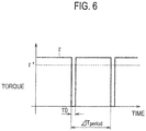
- the current command converter 6 of the microcomputer 5 generates the current command values Id*, Iq* (Idl*, Iql*; Idr*, Iqr*) relative to the electric motors 1, 2 such that the time average of the torque ⁇ actually outputted by the electric motors 1, 2 is allowed to match with the torque command value ⁇ * (i.e., time average of torque ⁇ is allowed to follow the torque command value ⁇ *) as shown in Fig. 6 while a period T0 in which the winding wire currents Id, Iq (Idl, Iql; Idr, Iqr) of the electric motors 1, 2 are each 0 is formed.
- a period ⁇ Tperiod for providing the period T0 in which the winding wire currents Id, Iq (Idl, Iql; Idr, Iqr) of the electric motors 1, 2 are each 0 is set, for example, per 1 second, to thereby synchronize this operation with the interruption processing by the magnet temperature anomaly detector 30.
- a timing at which the winding wire currents Id, Iq (Idl, Iql; Idr, Iqr) of the electric motors 1, 2 are each 0 can be generated in accordance with the processing of the magnet temperature anomaly detector 30, and the scene which makes it possible to implement the anomaly determination of the magnet temperature by using the ratio Vqr/Vql of the q-axis voltages of the electric motors 1, 2 can be increased.
- the current command converter 6 of the microcomputer 5 generates the current command values Id*, Iq* (Idl*, Iql*; Idr*, Iqr*) relative to the electric motors 1, 2 such that the time average of the torque ⁇ actually outputted by the electric motors 1, 2 is allowed to follow the torque command value ⁇ * while the period T0 in which the winding wire currents Id, Iq (Idl, Iql; Idr, Iqr) of the electric motors 1, 2 are each 0 is formed.
- the effect by the second embodiment can be exerted to a maximum extent without causing any inconvenience such as an inadvertent fluctuation of the output torque of the electric motors 1, 2.
- the difference of the q-axis voltage command values relative to the permanent magnet synchronous motors is used for determining whether or not an anomaly of the magnet temperature is caused to at least any one of the permanent magnet synchronous motors.
Landscapes
- Engineering & Computer Science (AREA)
- Power Engineering (AREA)
- Life Sciences & Earth Sciences (AREA)
- Sustainable Development (AREA)
- Sustainable Energy (AREA)
- Transportation (AREA)
- Mechanical Engineering (AREA)
- Control Of Ac Motors In General (AREA)
- Electric Propulsion And Braking For Vehicles (AREA)
- Control Of Motors That Do Not Use Commutators (AREA)
- Control Of Multiple Motors (AREA)
Claims (14)
- Eine Störungserkennungsvorrichtung für einen Permanentmagnet-Synchronelektromotor (1, 2), umfassend:eine Vielzahl von Permanentmagnet-Synchronelektromotoren (1, 2)einen Strombefehlswertrechner (6), der konfiguriert ist, um Strombefehlswerte relativ zu der Vielzahl der Permanentmagnet-Synchronelektromotoren (1, 2) zu berechnen; undq-Achsen-Spannungsbefehlswertberechner (18, 28), die so konfiguriert sind, dass sie jeden der q-Achsen-Spannungsbefehlswerte relativ zu den mehreren Permanentmagnet-Synchronelektromotoren (1, 2) basierend auf den Strombefehlswerten berechnen, die jeweils durch den Strombefehlswertrechner (6) berechnet werden; charakterisiert durch:
einen Magnettemperaturanomalie-Bestimmer (30), der konfiguriert ist, um zu bestimmen, ob eine Anomalie einer Magnettemperatur an mindestens einem der Permanentmagnet- Synchronelektromotoren (1, 2) verursacht wird oder nicht, und konfiguriert ist, eine Differenz zu nutzen zwischen:einem q-Achsen-Spannungsbefehlswert (Vqr*), der von einem der q-Achsen-Spannungsbefehlswertberechner (18, 28) berechnet wird und relativ zu einem Permanentmagnet-Synchronelektromotor (1, 2) der Vielzahl von Permanentmagnet-Synchronelektromotoren (1, 2) ist, undeinem q-Achsen-Spannungsbefehlswert (Vql*), der von einem anderen der q-Achsen-Spannungsbefehlswertberechner (28, 18) berechnet wird und relativ zu einem anderen Permanentmagnet-Synchronelektromotor (2, 1) der Vielzahl von Permanentmagnet-Synchronelektromotoren (1, 2) ist. - Die Störungserkennungsvorrichtung für einen Permanentmagnet-Synchronelektromotor (1, 2) gemäß Anspruch 1, wobei
wenn die Differenz zwischen dem q-Achsen-Spannungsbefehlswert relativ zu dem einen Permanentmagnet- Synchronelektromotor (1, 2) der Vielzahl der Permanentmagnet-Synchronelektromotoren (1, 2) und dem q-Achsen-Spannungsbefehlswert der relativ zu dem anderen Permanentmagnet-Synchronelektromotor (2, 1) der Vielzahl der Permanentmagnet-Synchronelektromotoren (1, 2) höher als ein vorbestimmter Schwellenwert ist, der im Voraus eingestellt wird, bestimmt der Magnettemperaturanomalie-Bestimmer (30), dass die Anomalie der Magnettemperatur durch mindestens einen der Permanentmagnet-Synchronelektromotoren (1, 2) bewirkt wird. - Die Störungserkennungsvorrichtung für einen Permanentmagnet-Synchronelektromotor (1, 2) gemäß Anspruch 1, wobei
der Magnettemperaturanomalie-Bestimmer (30) ein Änderungsverhältnis einer zeitlichen Änderung der Differenz zwischen dem q-Achsen-Spannungsbefehlswert relativ zu dem einen Permanentmagnet-Synchronelektromotor (1, 2) der Vielzahl der Permanentmagnet-Synchronelektromotoren (1, 2) und dem q-Achsen-Spannungsbefehlswert relativ zu dem anderen Permanentmagnet-Synchronelektromotor (2, 1) der Vielzahl der Permanentmagnet-Synchronelektromotoren (1, 2) berechnet und
wenn das Änderungsverhältnis größer als ein vorher festgelegter Schwellenwert ist, bestimmt der Magnettemperaturanomalie-Bestimmer (30), dass die Anomalie der Magnettemperatur durch mindestens einen der Permanentmagnet-Synchronelektromotoren (1, 2) verursacht wird. - Die Störungserkennungsvorrichtung für einen Permanentmagnet-Synchronelektromotor (1, 2) gemäß Anspruch 2 oder 3, wobei
wenn in der Vielzahl der Permanentmagnet-Synchronelektromotoren (1, 2) die zugehörigen Rotordrehzahlen im Wesentlichen gleich sind, die zugehörigen Wicklungsdrahtströme im Wesentlichen gleich sind und die zugehörigen Wicklungsdrahtinduktivitäten im Wesentlichen gleich sind, führt der Magnettemperaturanomalie-Bestimmer (30) die Bestimmung der Anomalie der Magnettemperatur aus. - Die Störungserkennungsvorrichtung für einen Permanentmagnet-Synchronelektromotor (1, 2) gemäß Anspruch 1, wobei
der Magnettemperaturanomalie-Bestimmer (30) verwendet:die Differenz zwischen dem q-Achsen-Spannungsbefehlswert relativ zu dem einen Permanentmagnet-Synchronelektromotor (1, 2) der Vielzahl der Permanentmagnet-Synchronelektromotoren (1, 2) und dem q-Achsen-Spannungsbefehlswert relativ zu dem anderer Permanentmagnet- Synchronelektromotor (2, 1) der Vielzahl der Permanentmagnet-Synchronelektromotoren (1, 2),Rotordrehzahlen der Permanentmagnet-Synchronelektromotoren (1, 2) undWickeldrahtströme der Permanentmagnet-Synchronelektromotoren (1, 2),um dadurch eine Differenz der Verkettungsmagnetflüsse der Permanentmagnet-Synchronelektromotoren (1, 2) zu berechnen, undwenn die Differenz der Verkettungsmagnetflüsse größer als ein vorbestimmter Schwellenwert, der im Voraus eingestellt wurde, ist bestimmt der Magnettemperaturanomalie-Bestimmer (30), dass die Anomalie der Magnettemperatur an mindestens einem der Permanentmagnet-Synchronelektromotoren (1, 2) verursacht wird. - Die Störungserkennungsvorrichtung für einen Permanentmagnet-Synchronelektromotor (1, 2) gemäß Anspruch 1, wobei
der Magnettemperaturanomalie-Bestimmer (30) verwendet:die Differenz zwischen dem q-Achsen-Spannungsbefehlswert relativ zu dem einen Permanentmagnet-Synchronelektromotor (1, 2) der Vielzahl der Permanentmagnet-Synchronelektromotoren (1, 2) und dem q-Achsen-Spannungsbefehlswert relativ zu dem anderer Permanentmagnet- Synchronelektromotor (2, 1) der Vielzahl der Permanentmagnet-Synchronelektromotoren (1, 2),die Rotordrehzahlen der Permanentmagnet-Synchronelektromotoren (1, 2) unddie Wickeldrahtströme der Permanentmagnet-Synchronelektromotoren (1, 2),um dadurch eine Differenz der Verkettungsmagnetflüsse der Permanentmagnet-Synchronelektromotoren (1, 2) zu berechnen, undder Magnettemperaturanomalie-Bestimmer (30) ein Änderungsverhältnis einer zeitlichen Änderung der Differenz der Verkettungsmagnetflüsse berechnet, undwenn das Änderungsverhältnis größer als ein vorbestimmter Schwellenwert ist, bestimmt der Magnettemperaturanomalie-Bestimmer (30), dass die Anomalie der Magnettemperatur an mindestens einem der Permanentmagnet-Synchronelektromotoren (1, 2) verursacht wird. - Die Störungserkennungsvorrichtung für einen Permanentmagnet-Synchronelektromotor (1, 2) gemäß Anspruch 5 oder 6, wobei
wenn in der Vielzahl der Permanentmagnet-Synchronelektromotoren (1, 2) die zugehörigen Rotordrehzahlen im Wesentlichen gleich sind, die zugehörigen Wicklungsdrahtströme im Wesentlichen gleich sind und die zugehörigen Wicklungsdrahtinduktivitäten im Wesentlichen gleich sind, führt der Magnettemperaturanomalie-Bestimmer (30) die Bestimmung der Anomalie der Magnettemperatur aus. - Die Störungserkennungsvorrichtung für einen Permanentmagnet-Synchronelektromotor (1, 2) gemäß Anspruch 5 oder 6, des weiteren umfassend:einen Speicher (6) zum Speichern einer Karte, die eine Beziehung zwischen einem d-Achsenstrom und einer Wicklungsdrahtinduktivität und eine Beziehung zwischen einem q-Achsenstrom und der Wicklungsdrahtinduktivität zeigt, wobeider Magnettemperaturanomalie-Bestimmer (30) die Wicklungsdrahtinduktivitäten der Vielzahl der Permanentmagnet-Synchronelektromotoren (1, 2) aus den Strombefehlswerten, die von dem Strombefehlswertrechner (6) berechnet werden, und aus der Karte, die in dem Speicher (6) gespeichert ist, berechnet,der Magnettemperaturanomalie-Bestimmer (30) verwendet:die Differenz zwischen dem q-Achsen-Spannungsbefehlswert relativ zu dem einen Permanentmagnet-Synchronelektromotor (1, 2) der Vielzahl der Permanentmagnet-Synchronelektromotoren (1, 2) und dem q-Achsen-Spannungsbefehlswert relativ zu dem anderer Permanentmagnet- Synchronelektromotor (2, 1) der Vielzahl der Permanentmagnet-Synchronelektromotoren (1, 2),die Rotordrehzahlen der Permanentmagnet-Synchronelektromotoren (1, 2) unddie Wickeldrahtströme der Permanentmagnet-Synchronelektromotoren (1, 2),die Wickeldrahtinduktivitäten der Permanentmagnet-Synchronelektromotoren (1, 2),um dadurch die Differenz der Verkettungsmagnetflüsse der permanentmagnetischen Synchronmotoren (1, 2) zu berechnen.
- Die Störungserkennungsvorrichtung für einen Permanentmagnet-Synchronelektromotor (1, 2) gemäß Anspruch 1, wobei
der Magnettemperaturanomalie-Bestimmer (30) verwendet die Differenz und ein Verhältnis zwischen dem q-Achsen-Spannungsbefehlswert, der von einem der q-Achsen-Spannungsbefehlswertberechner (18, 28) berechnet wird, und relativ ist zu dem einen Permanentmagnet-Synchronelektromotor (1, 2) der Vielzahl der Permanentmagnet-Synchronelektromotoren (1, 2) und des q-Achsen-Spannungsbefehlswerts, der von dem anderen der q-Achsen-Spannungsbefehlswertberechner (28, 18) berechnet wird und relativ ist zu dem anderen Permanentmagnet-Synchronelektromotor (2, 1) der Vielzahl der Permanentmagnet-Synchronelektromotoren (1, 2), um dadurch zu bestimmen, ob die Anomalie der Magnettemperatur an mindestens einen der Permanentmagnet-Synchronelektromotoren (1, 2) verursacht wird, oder nicht. - Die Störungserkennungsvorrichtung für einen Permanentmagnet-Synchronelektromotor (1, 2) gemäß Anspruch 9, wobei
wenn alle der q-Achsen-Spannungsbefehlswerte relativ zu der Vielzahl der Permanentmagnet-Synchronelektromotoren (1, 2) größer oder gleich einer vorbestimmten unteren Grenze sind, die im Voraus eingestellt wurde, verwendet der Magnettemperaturanomalie-Bestimmer (30) das Verhältnis zwischen dem q-Achsen-Spannungsbefehlswert, der von dem einen der q-Achsen-Spannungsbefehlswertberechner (18, 28) berechnet wird, und relativ ist zu dem einen Permanentmagnet-Synchronelektromotor (1, 2) der Vielzahl der ist Permanentmagnet-Synchronelektromotoren (1, 2) und dem q-Achsen-Spannungsbefehlswert, der von dem anderen der q-Achsen-Spannungsbefehlswertberechner (28, 18) berechnet wird und relativ ist zu dem anderen Permanentmagnet-Synchronelektromotor (2, 1) der Vielzahl der Permanentmagnet-Synchronelektromotoren (1, 2), um dadurch zu bestimmen, ob die Anomalie der Magnettemperatur an mindestens einen der Permanentmagnet-Synchronelektromotoren (1, 2) verursacht wird oder nicht, und
wenn zumindest einer der q-Achsen-Spannungsbefehlswerte relativ zu der Vielzahl der Permanentmagnet-Synchronelektromotoren (1, 2) niedriger als die vorbestimmte untere Grenze ist, verwendet der Magnettemperaturanomalie-Bestimmer (30) die Differenz zwischen dem q-Achsen-Spannungsbefehlswert, der von dem einen der q-Achsen-Spannungsbefehlswertberechner (18, 28) berechnet wird, und relativ ist zu dem einen Permanentmagnet-Synchronelektromotor (1, 2) der Vielzahl der ist Permanentmagnet-Synchronelektromotoren (1, 2) und dem q-Achsen-Spannungsbefehlswert, der von dem anderen der q-Achsen-Spannungsbefehlswertberechner (28, 18) berechnet wird und relativ ist zu dem anderen Permanentmagnet-Synchronelektromotor (2, 1) der Vielzahl der Permanentmagnet-Synchronelektromotoren (1, 2), um dadurch zu bestimmen, ob die Anomalie der Magnettemperatur an mindestens einen der Permanentmagnet-Synchronelektromotoren (1, 2) verursacht wird, oder nicht. - Die Störungserkennungsvorrichtung für einen Permanentmagnet-Synchronelektromotor (1, 2) gemäß Anspruch 9, wobei
zu einem Zeitpunkt, zu dem Wicklungsdrahtströme der Vielzahl der Permanentmagnet-Synchronelektromotoren (1, 2) jeweils Null sind, führt der Magnettemperaturanomalie-Bestimmer (30) die Bestimmung der Anomalie der Magnettemperatur unter Verwendung des Verhältnisses der q-Achsen-Spannungsbefehlswerte aus. - Die Störungserkennungsvorrichtung für einen Permanentmagnet-Synchronelektromotor (1, 2) gemäß Anspruch 11, wobei
der Strombefehlswertrechner (6) berechnet die Strombefehlswerte relativ zu der Vielzahl der Permanentmagnet-Synchronelektromotoren (1, 2) derart, dass ein zeitlicher Mittelwert eines von der Vielzahl der Permanentmagnet-Synchronelektromotoren (1) ausgegebenen Drehmoments, einem Drehmomentbefehlswert folgen darf, während der Zeitpunkt, zu dem die Wicklungsdrahtströme der Vielzahl der Permanentmagnet-Synchronelektromotoren (1, 2) jeweils Null sind, gebildet wird. - Die Störungserkennungsvorrichtung für einen Permanentmagnet-Synchronelektromotor (1, 2) gemäß einem der Ansprüche 9 bis 12, des weiteren umfassend
einen Verkettungsmagnetflussrechner zum Berechnen eines Wertes eines Verkettungsmagnetflusses jedes der Permanentmagnet-Synchronelektromotoren (1, 2) basierend auf der Differenz und dem Verhältnis der q-Achsen-Spannungsbefehlswerte, die durch die q-Achsen-Spannungsbefehlswertberechner (18, 28) berechnet werden und relativ zu der Vielzahl der Permanentmagnet-Synchronelektromotoren (1, 2) sind, wobei
basierend auf Drehmomentbefehlswerten relativ zu der Vielzahl der Permanentmagnet-Synchronelektromotoren (1, 2) und auf den Werten der Verkettungsmagnetflüsse der Vielzahl der Permanentmagnet-Synchronelektromotoren (1, 2) der Strombefehlswertrechner (6) die Strombefehlswerte relativ zu der Vielzahl der Permanentmagnet-Synchronelektromotoren (1, 2) berechnet. - Ein Störungserkennungsverfahren für einen Permanentmagnet-Synchronelektromotor (1, 2), umfassend:Berechnen von Strombefehlswerten relativ zu der Vielzahl der Permanentmagnet-Synchronelektromotoren (1, 2); undBerechnen jedes der q-Achsen-Spannungsbefehlswerte relativ zu der Vielzahl der Permanentmagnet-Synchronelektromotoren (1, 2) basierend auf den Strombefehlswerten, die jeweils durch den Strombefehlswertberechnungsvorgang berechnet werden; gekennzeichnet durchBestimmen, ob eine Anomalie einer Magnettemperatur an mindestens einem der Permanentmagnet-Synchronelektromotoren (1, 2) verursacht wird oder nicht, wobei der Bestimmungsvorgang implementiert ist eine Differenz zu verwenden zwischen:einem q-Achsen-Spannungsbefehlswert (Vqr*), der von einem der q-Achsen-Spannungsbefehlswertberechnungsvorgängen berechnet wird und relativ zu einem Permanentmagnet-Synchronelektromotor (1, 2) der Vielzahl von Permanentmagnet-Synchronelektromotoren (1, 2) ist, undeinem q-Achsen-Spannungsbefehlswert (Vql*), der von einem anderen der q-Achsen- Spannungsbefehlswertberechnungsvorgängen berechnet wird und relativ zu einem anderen Permanentmagnet-Synchronelektromotor (2, 1) der Vielzahl von Permanentmagnet- Synchronelektromotoren (1, 2) ist.
Applications Claiming Priority (2)
| Application Number | Priority Date | Filing Date | Title |
|---|---|---|---|
| JP2009198041 | 2009-08-28 | ||
| PCT/JP2010/064554 WO2011024935A1 (ja) | 2009-08-28 | 2010-08-27 | 永久磁石型同期電動機の異常検出装置 |
Publications (3)
| Publication Number | Publication Date |
|---|---|
| EP2472716A1 EP2472716A1 (de) | 2012-07-04 |
| EP2472716A4 EP2472716A4 (de) | 2017-05-24 |
| EP2472716B1 true EP2472716B1 (de) | 2019-07-10 |
Family
ID=43628034
Family Applications (1)
| Application Number | Title | Priority Date | Filing Date |
|---|---|---|---|
| EP10811984.3A Active EP2472716B1 (de) | 2009-08-28 | 2010-08-27 | Störungserkennungsvorrichtung für einen synchronen permanentmagnetelektromotor |
Country Status (5)
| Country | Link |
|---|---|
| US (1) | US8791716B2 (de) |
| EP (1) | EP2472716B1 (de) |
| JP (1) | JP5331208B2 (de) |
| CN (1) | CN102484438B (de) |
| WO (1) | WO2011024935A1 (de) |
Families Citing this family (33)
| Publication number | Priority date | Publication date | Assignee | Title |
|---|---|---|---|---|
| EP2571158B1 (de) * | 2010-05-14 | 2018-08-01 | Mitsubishi Electric Corporation | Bürstenloser antrieb |
| TWI416151B (zh) * | 2011-07-04 | 2013-11-21 | Delta Electronics Inc | 退磁偵測裝置及其退磁偵測方法 |
| JP5149431B2 (ja) * | 2011-07-29 | 2013-02-20 | ファナック株式会社 | 電動機の可動子の温度を検出する温度検出装置 |
| JP5243651B2 (ja) * | 2011-10-12 | 2013-07-24 | ファナック株式会社 | 永久磁石同期電動機のd軸電流を制御するモータ制御装置 |
| JP5886008B2 (ja) * | 2011-11-18 | 2016-03-16 | Ntn株式会社 | 電気自動車のモータ制御装置 |
| JP5420006B2 (ja) * | 2012-03-22 | 2014-02-19 | 三菱電機株式会社 | 同期機制御装置 |
| US9484791B2 (en) * | 2012-08-08 | 2016-11-01 | Infineon Technologies Ag | Remote rotor parameter sensor for electric drives |
| CN102841314A (zh) * | 2012-09-21 | 2012-12-26 | 南车株洲电力机车研究所有限公司 | 一种电励磁同步电机的温升试验方法与系统 |
| JP5823055B2 (ja) * | 2012-10-11 | 2015-11-25 | 三菱電機株式会社 | モータ制御装置およびモータ制御方法 |
| JP5695013B2 (ja) * | 2012-11-02 | 2015-04-01 | 本田技研工業株式会社 | 回転電機の磁石温度推定装置及び磁石温度推定方法 |
| JP2014113977A (ja) * | 2012-12-12 | 2014-06-26 | Toyota Motor Corp | 電動車両の制御装置 |
| JP5742879B2 (ja) * | 2013-05-21 | 2015-07-01 | トヨタ自動車株式会社 | 車両用の回転電機の制御装置 |
| FR3006125B1 (fr) * | 2013-05-21 | 2015-05-15 | Ifp Energies Now | Procede et systeme de determination de temperatures internes d'une machine electrique synchrone au moyens d'observateurs d'etat |
| CN103439657B (zh) * | 2013-07-23 | 2016-05-11 | 南京康尼机电股份有限公司 | 交流伺服电机传动参数检测方法及其在故障检测中的应用 |
| JP6211353B2 (ja) | 2013-09-03 | 2017-10-11 | Ntn株式会社 | 電気自動車の制御装置 |
| JP6245472B2 (ja) * | 2013-12-26 | 2017-12-13 | 東海旅客鉄道株式会社 | 電気車制御装置 |
| CN104852356B (zh) * | 2014-02-17 | 2018-09-21 | 伊顿公司 | 电动机的控制保护装置 |
| EP2919026B1 (de) * | 2014-03-11 | 2021-10-27 | ABB Schweiz AG | Verfahren und System zur Bestimmung einer Synchronmaschinenstörung |
| CN103956954B (zh) * | 2014-03-27 | 2017-03-29 | 广东美的制冷设备有限公司 | 永磁同步电机转子退磁的检测方法和检测装置 |
| DE102014220208A1 (de) * | 2014-10-07 | 2016-05-25 | Robert Bosch Gmbh | Steuervorrichtung für eine elektromaschine, fahrzeug und verfahren |
| KR102480750B1 (ko) * | 2015-01-08 | 2022-12-27 | 삼성전자주식회사 | 모터 구동 장치 및 그 제어 방법 |
| CN104700979B (zh) * | 2015-03-30 | 2017-07-11 | 广东美芝制冷设备有限公司 | 压缩机电机的退磁电流检测方法、装置 |
| CN106642516B (zh) * | 2016-09-08 | 2019-07-16 | 四川长虹电器股份有限公司 | 一种检测电机温度的方法及空调设备 |
| EP3382863B1 (de) * | 2017-03-30 | 2021-08-11 | ABB Schweiz AG | Verfahren zur erkennung eines rotorstabfehlers |
| JP6420405B1 (ja) | 2017-05-02 | 2018-11-07 | ファナック株式会社 | 異常診断装置および異常診断方法 |
| KR101988333B1 (ko) * | 2017-12-05 | 2019-06-12 | 장남철 | 단일제어기가 구비되는 듀얼 bldc 모터 |
| CN108173462B (zh) * | 2017-12-13 | 2020-06-26 | 天津津航计算技术研究所 | 一种两电机转矩平衡控制方法 |
| WO2019239657A1 (ja) * | 2018-06-12 | 2019-12-19 | 株式会社日立製作所 | 永久磁石同期電動機の駆動装置、駆動システムおよび駆動方法 |
| RU186188U1 (ru) * | 2018-09-17 | 2019-01-11 | Федеральное государственное бюджетное образовательное учреждение высшего образования "Омский государственный университет путей сообщения" | Стенд для испытания асинхронных машин |
| JP7312065B2 (ja) * | 2019-09-11 | 2023-07-20 | 日立Astemo株式会社 | モータ制御装置、機電一体ユニット、発電機システム、モータ駆動装置および電動車両システム |
| CN112994575B (zh) * | 2019-12-17 | 2023-01-31 | 青岛海尔空调电子有限公司 | 三相压缩机的绕组温度确定方法、启动方法以及空调器 |
| CN115298559A (zh) * | 2020-03-20 | 2022-11-04 | 麦格纳国际公司 | 用于永磁同步马达的永磁磁链确定 |
| CN114859223A (zh) * | 2021-02-03 | 2022-08-05 | 台达电子工业股份有限公司 | 马达退磁检测方法与马达退磁检测装置 |
Family Cites Families (13)
| Publication number | Priority date | Publication date | Assignee | Title |
|---|---|---|---|---|
| JP3496518B2 (ja) * | 1998-06-10 | 2004-02-16 | 日産自動車株式会社 | 回転電機の制御装置 |
| JP4548886B2 (ja) * | 1999-12-27 | 2010-09-22 | 東洋電機製造株式会社 | 永久磁石型同期電動機の制御装置 |
| JP2002095300A (ja) | 2000-09-19 | 2002-03-29 | Meidensha Corp | 永久磁石同期電動機の制御方法 |
| DE10212751A1 (de) * | 2002-03-22 | 2003-10-02 | Bosch Gmbh Robert | Verfahren und Vorrichtung zur Ermittlung der Rotortemperatur bei einer PM-Synchronmaschine |
| JP4023249B2 (ja) * | 2002-07-25 | 2007-12-19 | ダイキン工業株式会社 | 圧縮機内部状態推定装置及び空気調和装置 |
| JP3818237B2 (ja) * | 2002-08-08 | 2006-09-06 | 日産自動車株式会社 | 同期電動機の制御装置 |
| JP4716680B2 (ja) * | 2004-06-29 | 2011-07-06 | 東洋電機製造株式会社 | 永久磁石型同期電動機の制御装置 |
| DE102005062588A1 (de) * | 2005-12-27 | 2007-06-28 | Robert Bosch Gmbh | Verfahren zum Bestimmen der Magnettemperatur bei Synchronmaschinen |
| JP2007274779A (ja) * | 2006-03-30 | 2007-10-18 | Aisin Aw Co Ltd | 電動駆動制御装置及び電動駆動制御方法 |
| US7595600B2 (en) * | 2007-06-07 | 2009-09-29 | Gm Global Technology Operations, Inc. | Method and system for torque control in permanent magnet machines |
| JP2009072049A (ja) * | 2007-09-18 | 2009-04-02 | Toshiba Corp | 電気車制御装置 |
| JP2009198041A (ja) | 2008-02-20 | 2009-09-03 | Panasonic Corp | 空気調和機 |
| US8421255B2 (en) * | 2009-10-28 | 2013-04-16 | General Electric Company | System and method for determining the temperature of a permanent magnet in a machine |
-
2010
- 2010-08-27 EP EP10811984.3A patent/EP2472716B1/de active Active
- 2010-08-27 CN CN201080038456.7A patent/CN102484438B/zh active Active
- 2010-08-27 WO PCT/JP2010/064554 patent/WO2011024935A1/ja active Application Filing
- 2010-08-27 JP JP2011528860A patent/JP5331208B2/ja active Active
- 2010-08-27 US US13/391,860 patent/US8791716B2/en active Active
Non-Patent Citations (1)
| Title |
|---|
| None * |
Also Published As
| Publication number | Publication date |
|---|---|
| US20120146683A1 (en) | 2012-06-14 |
| CN102484438A (zh) | 2012-05-30 |
| JP5331208B2 (ja) | 2013-10-30 |
| JPWO2011024935A1 (ja) | 2013-01-31 |
| WO2011024935A1 (ja) | 2011-03-03 |
| EP2472716A4 (de) | 2017-05-24 |
| EP2472716A1 (de) | 2012-07-04 |
| CN102484438B (zh) | 2015-04-01 |
| US8791716B2 (en) | 2014-07-29 |
Similar Documents
| Publication | Publication Date | Title |
|---|---|---|
| EP2472716B1 (de) | Störungserkennungsvorrichtung für einen synchronen permanentmagnetelektromotor | |
| JP5130031B2 (ja) | 永久磁石モータの位置センサレス制御装置 | |
| US6788024B2 (en) | Position-sensorless motor control method and apparatus | |
| US7528568B2 (en) | Vector controller for permanent magnet synchronous motor | |
| US9054630B2 (en) | Synchronous machine controller | |
| US10418929B2 (en) | Synchronous machine control device and permanent magnet temperature estimation method for synchronous machine | |
| JP5198332B2 (ja) | 永久磁石同期電動機のトルク制御装置 | |
| US20090322262A1 (en) | Controller For Permanent Magnet Synchronous Motor and Motor Control System | |
| EP2622733B1 (de) | Motorsteuerungsvorrichtung | |
| EP1796260A1 (de) | Vektorsteuerung eines induktionsmotors | |
| EP3537601B1 (de) | Motorsteuerungsverfahren | |
| US20150222216A1 (en) | Motor control device, and motor control method | |
| KR101619567B1 (ko) | 유도전동기의 파라미터 추정장치 | |
| US10756601B2 (en) | Control method and control system of motor rotation speed | |
| JP2009089552A (ja) | モータ駆動制御装置及びモータ駆動制御装置を使用した電動パワーステアリング装置 | |
| EP2704311A2 (de) | Vorrichtung zur Schätzung der Parameter in Induktionsmotor | |
| JP2010200515A (ja) | 電動機の磁石温度推定装置 | |
| EP3950403A1 (de) | Antriebsvorrichtung für eine dauermagnet-synchronmaschine, drehmomentkompensationsverfahren für eine dauermagnet-synchronmaschine und elektrisches fahrzeug | |
| KR100921115B1 (ko) | 영구자석 동기 모터 제어시스템 및 제어방법 | |
| JP2009278760A (ja) | モータ制御装置及びモータ制御方法 | |
| US11177753B2 (en) | Electric machine control system and control method thereof | |
| EP2169820B1 (de) | Wechselstrommotor-Steuerungsvorrichtung | |
| JP3692929B2 (ja) | モータ制御装置 | |
| JP5332301B2 (ja) | 永久磁石形同期電動機の制御装置 | |
| WO2021240883A1 (ja) | モータ制御装置およびモータ制御方法 |
Legal Events
| Date | Code | Title | Description |
|---|---|---|---|
| PUAI | Public reference made under article 153(3) epc to a published international application that has entered the european phase |
Free format text: ORIGINAL CODE: 0009012 |
|
| 17P | Request for examination filed |
Effective date: 20120227 |
|
| AK | Designated contracting states |
Kind code of ref document: A1 Designated state(s): AL AT BE BG CH CY CZ DE DK EE ES FI FR GB GR HR HU IE IS IT LI LT LU LV MC MK MT NL NO PL PT RO SE SI SK SM TR |
|
| DAX | Request for extension of the european patent (deleted) | ||
| RA4 | Supplementary search report drawn up and despatched (corrected) |
Effective date: 20170424 |
|
| RIC1 | Information provided on ipc code assigned before grant |
Ipc: B60L 3/00 20060101ALI20170418BHEP Ipc: H02P 21/00 20160101ALI20170418BHEP Ipc: H02P 29/66 20160101ALI20170418BHEP Ipc: H02P 21/14 20160101ALI20170418BHEP Ipc: H02P 5/74 20060101AFI20170418BHEP Ipc: H02P 5/50 20160101ALI20170418BHEP Ipc: H02P 6/04 20160101ALI20170418BHEP Ipc: H02P 27/04 20160101ALI20170418BHEP |
|
| GRAP | Despatch of communication of intention to grant a patent |
Free format text: ORIGINAL CODE: EPIDOSNIGR1 |
|
| STAA | Information on the status of an ep patent application or granted ep patent |
Free format text: STATUS: GRANT OF PATENT IS INTENDED |
|
| INTG | Intention to grant announced |
Effective date: 20190322 |
|
| RIN1 | Information on inventor provided before grant (corrected) |
Inventor name: NAKANO, YOSHINORI Inventor name: IMAZU, TOMOYA Inventor name: TANIMOTO, TSUTOMU |
|
| RAP1 | Party data changed (applicant data changed or rights of an application transferred) |
Owner name: NISSAN MOTOR CO., LTD. Owner name: MEIDENSHA CORPORATION |
|
| RIN1 | Information on inventor provided before grant (corrected) |
Inventor name: TANIMOTO, TSUTOMU Inventor name: NAKANO, YOSHINORI Inventor name: IMAZU, TOMOYA |
|
| GRAS | Grant fee paid |
Free format text: ORIGINAL CODE: EPIDOSNIGR3 |
|
| GRAA | (expected) grant |
Free format text: ORIGINAL CODE: 0009210 |
|
| STAA | Information on the status of an ep patent application or granted ep patent |
Free format text: STATUS: THE PATENT HAS BEEN GRANTED |
|
| AK | Designated contracting states |
Kind code of ref document: B1 Designated state(s): AL AT BE BG CH CY CZ DE DK EE ES FI FR GB GR HR HU IE IS IT LI LT LU LV MC MK MT NL NO PL PT RO SE SI SK SM TR |
|
| REG | Reference to a national code |
Ref country code: GB Ref legal event code: FG4D |
|
| RIN1 | Information on inventor provided before grant (corrected) |
Inventor name: NAKANO, YOSHINORI Inventor name: TANIMOTO, TSUTOMU Inventor name: IMAZU, TOMOYA |
|
| REG | Reference to a national code |
Ref country code: CH Ref legal event code: EP Ref country code: AT Ref legal event code: REF Ref document number: 1154557 Country of ref document: AT Kind code of ref document: T Effective date: 20190715 |
|
| REG | Reference to a national code |
Ref country code: DE Ref legal event code: R096 Ref document number: 602010059975 Country of ref document: DE |
|
| REG | Reference to a national code |
Ref country code: IE Ref legal event code: FG4D |
|
| REG | Reference to a national code |
Ref country code: NL Ref legal event code: MP Effective date: 20190710 |
|
| REG | Reference to a national code |
Ref country code: LT Ref legal event code: MG4D |
|
| REG | Reference to a national code |
Ref country code: AT Ref legal event code: MK05 Ref document number: 1154557 Country of ref document: AT Kind code of ref document: T Effective date: 20190710 |
|
| PG25 | Lapsed in a contracting state [announced via postgrant information from national office to epo] |
Ref country code: PT Free format text: LAPSE BECAUSE OF FAILURE TO SUBMIT A TRANSLATION OF THE DESCRIPTION OR TO PAY THE FEE WITHIN THE PRESCRIBED TIME-LIMIT Effective date: 20191111 Ref country code: HR Free format text: LAPSE BECAUSE OF FAILURE TO SUBMIT A TRANSLATION OF THE DESCRIPTION OR TO PAY THE FEE WITHIN THE PRESCRIBED TIME-LIMIT Effective date: 20190710 Ref country code: NL Free format text: LAPSE BECAUSE OF FAILURE TO SUBMIT A TRANSLATION OF THE DESCRIPTION OR TO PAY THE FEE WITHIN THE PRESCRIBED TIME-LIMIT Effective date: 20190710 Ref country code: SE Free format text: LAPSE BECAUSE OF FAILURE TO SUBMIT A TRANSLATION OF THE DESCRIPTION OR TO PAY THE FEE WITHIN THE PRESCRIBED TIME-LIMIT Effective date: 20190710 Ref country code: AT Free format text: LAPSE BECAUSE OF FAILURE TO SUBMIT A TRANSLATION OF THE DESCRIPTION OR TO PAY THE FEE WITHIN THE PRESCRIBED TIME-LIMIT Effective date: 20190710 Ref country code: BG Free format text: LAPSE BECAUSE OF FAILURE TO SUBMIT A TRANSLATION OF THE DESCRIPTION OR TO PAY THE FEE WITHIN THE PRESCRIBED TIME-LIMIT Effective date: 20191010 Ref country code: LT Free format text: LAPSE BECAUSE OF FAILURE TO SUBMIT A TRANSLATION OF THE DESCRIPTION OR TO PAY THE FEE WITHIN THE PRESCRIBED TIME-LIMIT Effective date: 20190710 Ref country code: NO Free format text: LAPSE BECAUSE OF FAILURE TO SUBMIT A TRANSLATION OF THE DESCRIPTION OR TO PAY THE FEE WITHIN THE PRESCRIBED TIME-LIMIT Effective date: 20191010 Ref country code: FI Free format text: LAPSE BECAUSE OF FAILURE TO SUBMIT A TRANSLATION OF THE DESCRIPTION OR TO PAY THE FEE WITHIN THE PRESCRIBED TIME-LIMIT Effective date: 20190710 |
|
| PG25 | Lapsed in a contracting state [announced via postgrant information from national office to epo] |
Ref country code: IS Free format text: LAPSE BECAUSE OF FAILURE TO SUBMIT A TRANSLATION OF THE DESCRIPTION OR TO PAY THE FEE WITHIN THE PRESCRIBED TIME-LIMIT Effective date: 20191110 Ref country code: GR Free format text: LAPSE BECAUSE OF FAILURE TO SUBMIT A TRANSLATION OF THE DESCRIPTION OR TO PAY THE FEE WITHIN THE PRESCRIBED TIME-LIMIT Effective date: 20191011 Ref country code: ES Free format text: LAPSE BECAUSE OF FAILURE TO SUBMIT A TRANSLATION OF THE DESCRIPTION OR TO PAY THE FEE WITHIN THE PRESCRIBED TIME-LIMIT Effective date: 20190710 Ref country code: AL Free format text: LAPSE BECAUSE OF FAILURE TO SUBMIT A TRANSLATION OF THE DESCRIPTION OR TO PAY THE FEE WITHIN THE PRESCRIBED TIME-LIMIT Effective date: 20190710 Ref country code: LV Free format text: LAPSE BECAUSE OF FAILURE TO SUBMIT A TRANSLATION OF THE DESCRIPTION OR TO PAY THE FEE WITHIN THE PRESCRIBED TIME-LIMIT Effective date: 20190710 |
|
| PG25 | Lapsed in a contracting state [announced via postgrant information from national office to epo] |
Ref country code: TR Free format text: LAPSE BECAUSE OF FAILURE TO SUBMIT A TRANSLATION OF THE DESCRIPTION OR TO PAY THE FEE WITHIN THE PRESCRIBED TIME-LIMIT Effective date: 20190710 |
|
| PG25 | Lapsed in a contracting state [announced via postgrant information from national office to epo] |
Ref country code: EE Free format text: LAPSE BECAUSE OF FAILURE TO SUBMIT A TRANSLATION OF THE DESCRIPTION OR TO PAY THE FEE WITHIN THE PRESCRIBED TIME-LIMIT Effective date: 20190710 Ref country code: DK Free format text: LAPSE BECAUSE OF FAILURE TO SUBMIT A TRANSLATION OF THE DESCRIPTION OR TO PAY THE FEE WITHIN THE PRESCRIBED TIME-LIMIT Effective date: 20190710 Ref country code: IT Free format text: LAPSE BECAUSE OF FAILURE TO SUBMIT A TRANSLATION OF THE DESCRIPTION OR TO PAY THE FEE WITHIN THE PRESCRIBED TIME-LIMIT Effective date: 20190710 Ref country code: RO Free format text: LAPSE BECAUSE OF FAILURE TO SUBMIT A TRANSLATION OF THE DESCRIPTION OR TO PAY THE FEE WITHIN THE PRESCRIBED TIME-LIMIT Effective date: 20190710 Ref country code: PL Free format text: LAPSE BECAUSE OF FAILURE TO SUBMIT A TRANSLATION OF THE DESCRIPTION OR TO PAY THE FEE WITHIN THE PRESCRIBED TIME-LIMIT Effective date: 20190710 |
|
| PG25 | Lapsed in a contracting state [announced via postgrant information from national office to epo] |
Ref country code: IS Free format text: LAPSE BECAUSE OF FAILURE TO SUBMIT A TRANSLATION OF THE DESCRIPTION OR TO PAY THE FEE WITHIN THE PRESCRIBED TIME-LIMIT Effective date: 20200224 Ref country code: LU Free format text: LAPSE BECAUSE OF NON-PAYMENT OF DUE FEES Effective date: 20190827 Ref country code: SM Free format text: LAPSE BECAUSE OF FAILURE TO SUBMIT A TRANSLATION OF THE DESCRIPTION OR TO PAY THE FEE WITHIN THE PRESCRIBED TIME-LIMIT Effective date: 20190710 Ref country code: SK Free format text: LAPSE BECAUSE OF FAILURE TO SUBMIT A TRANSLATION OF THE DESCRIPTION OR TO PAY THE FEE WITHIN THE PRESCRIBED TIME-LIMIT Effective date: 20190710 Ref country code: MC Free format text: LAPSE BECAUSE OF FAILURE TO SUBMIT A TRANSLATION OF THE DESCRIPTION OR TO PAY THE FEE WITHIN THE PRESCRIBED TIME-LIMIT Effective date: 20190710 Ref country code: CH Free format text: LAPSE BECAUSE OF NON-PAYMENT OF DUE FEES Effective date: 20190831 Ref country code: CZ Free format text: LAPSE BECAUSE OF FAILURE TO SUBMIT A TRANSLATION OF THE DESCRIPTION OR TO PAY THE FEE WITHIN THE PRESCRIBED TIME-LIMIT Effective date: 20190710 Ref country code: LI Free format text: LAPSE BECAUSE OF NON-PAYMENT OF DUE FEES Effective date: 20190831 |
|
| REG | Reference to a national code |
Ref country code: BE Ref legal event code: MM Effective date: 20190831 |
|
| REG | Reference to a national code |
Ref country code: DE Ref legal event code: R097 Ref document number: 602010059975 Country of ref document: DE |
|
| PLBE | No opposition filed within time limit |
Free format text: ORIGINAL CODE: 0009261 |
|
| STAA | Information on the status of an ep patent application or granted ep patent |
Free format text: STATUS: NO OPPOSITION FILED WITHIN TIME LIMIT |
|
| PG2D | Information on lapse in contracting state deleted |
Ref country code: IS |
|
| PG25 | Lapsed in a contracting state [announced via postgrant information from national office to epo] |
Ref country code: IE Free format text: LAPSE BECAUSE OF NON-PAYMENT OF DUE FEES Effective date: 20190827 |
|
| 26N | No opposition filed |
Effective date: 20200603 |
|
| PG25 | Lapsed in a contracting state [announced via postgrant information from national office to epo] |
Ref country code: SI Free format text: LAPSE BECAUSE OF FAILURE TO SUBMIT A TRANSLATION OF THE DESCRIPTION OR TO PAY THE FEE WITHIN THE PRESCRIBED TIME-LIMIT Effective date: 20190710 Ref country code: BE Free format text: LAPSE BECAUSE OF NON-PAYMENT OF DUE FEES Effective date: 20190831 |
|
| PG25 | Lapsed in a contracting state [announced via postgrant information from national office to epo] |
Ref country code: CY Free format text: LAPSE BECAUSE OF FAILURE TO SUBMIT A TRANSLATION OF THE DESCRIPTION OR TO PAY THE FEE WITHIN THE PRESCRIBED TIME-LIMIT Effective date: 20190710 |
|
| PG25 | Lapsed in a contracting state [announced via postgrant information from national office to epo] |
Ref country code: MT Free format text: LAPSE BECAUSE OF FAILURE TO SUBMIT A TRANSLATION OF THE DESCRIPTION OR TO PAY THE FEE WITHIN THE PRESCRIBED TIME-LIMIT Effective date: 20190710 Ref country code: HU Free format text: LAPSE BECAUSE OF FAILURE TO SUBMIT A TRANSLATION OF THE DESCRIPTION OR TO PAY THE FEE WITHIN THE PRESCRIBED TIME-LIMIT; INVALID AB INITIO Effective date: 20100827 |
|
| PG25 | Lapsed in a contracting state [announced via postgrant information from national office to epo] |
Ref country code: MK Free format text: LAPSE BECAUSE OF FAILURE TO SUBMIT A TRANSLATION OF THE DESCRIPTION OR TO PAY THE FEE WITHIN THE PRESCRIBED TIME-LIMIT Effective date: 20190710 |
|
| PGFP | Annual fee paid to national office [announced via postgrant information from national office to epo] |
Ref country code: GB Payment date: 20230720 Year of fee payment: 14 |
|
| PGFP | Annual fee paid to national office [announced via postgrant information from national office to epo] |
Ref country code: FR Payment date: 20230720 Year of fee payment: 14 Ref country code: DE Payment date: 20230720 Year of fee payment: 14 |