EP2471682B1 - Vehicle - Google Patents
Vehicle Download PDFInfo
- Publication number
- EP2471682B1 EP2471682B1 EP10851748.3A EP10851748A EP2471682B1 EP 2471682 B1 EP2471682 B1 EP 2471682B1 EP 10851748 A EP10851748 A EP 10851748A EP 2471682 B1 EP2471682 B1 EP 2471682B1
- Authority
- EP
- European Patent Office
- Prior art keywords
- voltage
- inverter
- storage device
- temperature
- power storage
- Prior art date
- Legal status (The legal status is an assumption and is not a legal conclusion. Google has not performed a legal analysis and makes no representation as to the accuracy of the status listed.)
- Active
Links
Images


Classifications
-
- B—PERFORMING OPERATIONS; TRANSPORTING
- B60—VEHICLES IN GENERAL
- B60L—PROPULSION OF ELECTRICALLY-PROPELLED VEHICLES; SUPPLYING ELECTRIC POWER FOR AUXILIARY EQUIPMENT OF ELECTRICALLY-PROPELLED VEHICLES; ELECTRODYNAMIC BRAKE SYSTEMS FOR VEHICLES IN GENERAL; MAGNETIC SUSPENSION OR LEVITATION FOR VEHICLES; MONITORING OPERATING VARIABLES OF ELECTRICALLY-PROPELLED VEHICLES; ELECTRIC SAFETY DEVICES FOR ELECTRICALLY-PROPELLED VEHICLES
- B60L3/00—Electric devices on electrically-propelled vehicles for safety purposes; Monitoring operating variables, e.g. speed, deceleration or energy consumption
- B60L3/0023—Detecting, eliminating, remedying or compensating for drive train abnormalities, e.g. failures within the drive train
- B60L3/003—Detecting, eliminating, remedying or compensating for drive train abnormalities, e.g. failures within the drive train relating to inverters
-
- B—PERFORMING OPERATIONS; TRANSPORTING
- B60—VEHICLES IN GENERAL
- B60L—PROPULSION OF ELECTRICALLY-PROPELLED VEHICLES; SUPPLYING ELECTRIC POWER FOR AUXILIARY EQUIPMENT OF ELECTRICALLY-PROPELLED VEHICLES; ELECTRODYNAMIC BRAKE SYSTEMS FOR VEHICLES IN GENERAL; MAGNETIC SUSPENSION OR LEVITATION FOR VEHICLES; MONITORING OPERATING VARIABLES OF ELECTRICALLY-PROPELLED VEHICLES; ELECTRIC SAFETY DEVICES FOR ELECTRICALLY-PROPELLED VEHICLES
- B60L15/00—Methods, circuits, or devices for controlling the traction-motor speed of electrically-propelled vehicles
- B60L15/20—Methods, circuits, or devices for controlling the traction-motor speed of electrically-propelled vehicles for control of the vehicle or its driving motor to achieve a desired performance, e.g. speed, torque, programmed variation of speed
- B60L15/2009—Methods, circuits, or devices for controlling the traction-motor speed of electrically-propelled vehicles for control of the vehicle or its driving motor to achieve a desired performance, e.g. speed, torque, programmed variation of speed for braking
-
- B—PERFORMING OPERATIONS; TRANSPORTING
- B60—VEHICLES IN GENERAL
- B60L—PROPULSION OF ELECTRICALLY-PROPELLED VEHICLES; SUPPLYING ELECTRIC POWER FOR AUXILIARY EQUIPMENT OF ELECTRICALLY-PROPELLED VEHICLES; ELECTRODYNAMIC BRAKE SYSTEMS FOR VEHICLES IN GENERAL; MAGNETIC SUSPENSION OR LEVITATION FOR VEHICLES; MONITORING OPERATING VARIABLES OF ELECTRICALLY-PROPELLED VEHICLES; ELECTRIC SAFETY DEVICES FOR ELECTRICALLY-PROPELLED VEHICLES
- B60L3/00—Electric devices on electrically-propelled vehicles for safety purposes; Monitoring operating variables, e.g. speed, deceleration or energy consumption
- B60L3/0023—Detecting, eliminating, remedying or compensating for drive train abnormalities, e.g. failures within the drive train
- B60L3/0046—Detecting, eliminating, remedying or compensating for drive train abnormalities, e.g. failures within the drive train relating to electric energy storage systems, e.g. batteries or capacitors
-
- B—PERFORMING OPERATIONS; TRANSPORTING
- B60—VEHICLES IN GENERAL
- B60L—PROPULSION OF ELECTRICALLY-PROPELLED VEHICLES; SUPPLYING ELECTRIC POWER FOR AUXILIARY EQUIPMENT OF ELECTRICALLY-PROPELLED VEHICLES; ELECTRODYNAMIC BRAKE SYSTEMS FOR VEHICLES IN GENERAL; MAGNETIC SUSPENSION OR LEVITATION FOR VEHICLES; MONITORING OPERATING VARIABLES OF ELECTRICALLY-PROPELLED VEHICLES; ELECTRIC SAFETY DEVICES FOR ELECTRICALLY-PROPELLED VEHICLES
- B60L3/00—Electric devices on electrically-propelled vehicles for safety purposes; Monitoring operating variables, e.g. speed, deceleration or energy consumption
- B60L3/04—Cutting off the power supply under fault conditions
-
- B—PERFORMING OPERATIONS; TRANSPORTING
- B60—VEHICLES IN GENERAL
- B60L—PROPULSION OF ELECTRICALLY-PROPELLED VEHICLES; SUPPLYING ELECTRIC POWER FOR AUXILIARY EQUIPMENT OF ELECTRICALLY-PROPELLED VEHICLES; ELECTRODYNAMIC BRAKE SYSTEMS FOR VEHICLES IN GENERAL; MAGNETIC SUSPENSION OR LEVITATION FOR VEHICLES; MONITORING OPERATING VARIABLES OF ELECTRICALLY-PROPELLED VEHICLES; ELECTRIC SAFETY DEVICES FOR ELECTRICALLY-PROPELLED VEHICLES
- B60L3/00—Electric devices on electrically-propelled vehicles for safety purposes; Monitoring operating variables, e.g. speed, deceleration or energy consumption
- B60L3/12—Recording operating variables ; Monitoring of operating variables
-
- B—PERFORMING OPERATIONS; TRANSPORTING
- B60—VEHICLES IN GENERAL
- B60L—PROPULSION OF ELECTRICALLY-PROPELLED VEHICLES; SUPPLYING ELECTRIC POWER FOR AUXILIARY EQUIPMENT OF ELECTRICALLY-PROPELLED VEHICLES; ELECTRODYNAMIC BRAKE SYSTEMS FOR VEHICLES IN GENERAL; MAGNETIC SUSPENSION OR LEVITATION FOR VEHICLES; MONITORING OPERATING VARIABLES OF ELECTRICALLY-PROPELLED VEHICLES; ELECTRIC SAFETY DEVICES FOR ELECTRICALLY-PROPELLED VEHICLES
- B60L50/00—Electric propulsion with power supplied within the vehicle
- B60L50/10—Electric propulsion with power supplied within the vehicle using propulsion power supplied by engine-driven generators, e.g. generators driven by combustion engines
- B60L50/16—Electric propulsion with power supplied within the vehicle using propulsion power supplied by engine-driven generators, e.g. generators driven by combustion engines with provision for separate direct mechanical propulsion
-
- B—PERFORMING OPERATIONS; TRANSPORTING
- B60—VEHICLES IN GENERAL
- B60L—PROPULSION OF ELECTRICALLY-PROPELLED VEHICLES; SUPPLYING ELECTRIC POWER FOR AUXILIARY EQUIPMENT OF ELECTRICALLY-PROPELLED VEHICLES; ELECTRODYNAMIC BRAKE SYSTEMS FOR VEHICLES IN GENERAL; MAGNETIC SUSPENSION OR LEVITATION FOR VEHICLES; MONITORING OPERATING VARIABLES OF ELECTRICALLY-PROPELLED VEHICLES; ELECTRIC SAFETY DEVICES FOR ELECTRICALLY-PROPELLED VEHICLES
- B60L50/00—Electric propulsion with power supplied within the vehicle
- B60L50/40—Electric propulsion with power supplied within the vehicle using propulsion power supplied by capacitors
-
- B—PERFORMING OPERATIONS; TRANSPORTING
- B60—VEHICLES IN GENERAL
- B60L—PROPULSION OF ELECTRICALLY-PROPELLED VEHICLES; SUPPLYING ELECTRIC POWER FOR AUXILIARY EQUIPMENT OF ELECTRICALLY-PROPELLED VEHICLES; ELECTRODYNAMIC BRAKE SYSTEMS FOR VEHICLES IN GENERAL; MAGNETIC SUSPENSION OR LEVITATION FOR VEHICLES; MONITORING OPERATING VARIABLES OF ELECTRICALLY-PROPELLED VEHICLES; ELECTRIC SAFETY DEVICES FOR ELECTRICALLY-PROPELLED VEHICLES
- B60L50/00—Electric propulsion with power supplied within the vehicle
- B60L50/50—Electric propulsion with power supplied within the vehicle using propulsion power supplied by batteries or fuel cells
- B60L50/60—Electric propulsion with power supplied within the vehicle using propulsion power supplied by batteries or fuel cells using power supplied by batteries
- B60L50/61—Electric propulsion with power supplied within the vehicle using propulsion power supplied by batteries or fuel cells using power supplied by batteries by batteries charged by engine-driven generators, e.g. series hybrid electric vehicles
-
- B—PERFORMING OPERATIONS; TRANSPORTING
- B60—VEHICLES IN GENERAL
- B60L—PROPULSION OF ELECTRICALLY-PROPELLED VEHICLES; SUPPLYING ELECTRIC POWER FOR AUXILIARY EQUIPMENT OF ELECTRICALLY-PROPELLED VEHICLES; ELECTRODYNAMIC BRAKE SYSTEMS FOR VEHICLES IN GENERAL; MAGNETIC SUSPENSION OR LEVITATION FOR VEHICLES; MONITORING OPERATING VARIABLES OF ELECTRICALLY-PROPELLED VEHICLES; ELECTRIC SAFETY DEVICES FOR ELECTRICALLY-PROPELLED VEHICLES
- B60L58/00—Methods or circuit arrangements for monitoring or controlling batteries or fuel cells, specially adapted for electric vehicles
- B60L58/10—Methods or circuit arrangements for monitoring or controlling batteries or fuel cells, specially adapted for electric vehicles for monitoring or controlling batteries
- B60L58/12—Methods or circuit arrangements for monitoring or controlling batteries or fuel cells, specially adapted for electric vehicles for monitoring or controlling batteries responding to state of charge [SoC]
- B60L58/14—Preventing excessive discharging
-
- B—PERFORMING OPERATIONS; TRANSPORTING
- B60—VEHICLES IN GENERAL
- B60L—PROPULSION OF ELECTRICALLY-PROPELLED VEHICLES; SUPPLYING ELECTRIC POWER FOR AUXILIARY EQUIPMENT OF ELECTRICALLY-PROPELLED VEHICLES; ELECTRODYNAMIC BRAKE SYSTEMS FOR VEHICLES IN GENERAL; MAGNETIC SUSPENSION OR LEVITATION FOR VEHICLES; MONITORING OPERATING VARIABLES OF ELECTRICALLY-PROPELLED VEHICLES; ELECTRIC SAFETY DEVICES FOR ELECTRICALLY-PROPELLED VEHICLES
- B60L58/00—Methods or circuit arrangements for monitoring or controlling batteries or fuel cells, specially adapted for electric vehicles
- B60L58/10—Methods or circuit arrangements for monitoring or controlling batteries or fuel cells, specially adapted for electric vehicles for monitoring or controlling batteries
- B60L58/24—Methods or circuit arrangements for monitoring or controlling batteries or fuel cells, specially adapted for electric vehicles for monitoring or controlling batteries for controlling the temperature of batteries
- B60L58/25—Methods or circuit arrangements for monitoring or controlling batteries or fuel cells, specially adapted for electric vehicles for monitoring or controlling batteries for controlling the temperature of batteries by controlling the electric load
-
- B—PERFORMING OPERATIONS; TRANSPORTING
- B60—VEHICLES IN GENERAL
- B60L—PROPULSION OF ELECTRICALLY-PROPELLED VEHICLES; SUPPLYING ELECTRIC POWER FOR AUXILIARY EQUIPMENT OF ELECTRICALLY-PROPELLED VEHICLES; ELECTRODYNAMIC BRAKE SYSTEMS FOR VEHICLES IN GENERAL; MAGNETIC SUSPENSION OR LEVITATION FOR VEHICLES; MONITORING OPERATING VARIABLES OF ELECTRICALLY-PROPELLED VEHICLES; ELECTRIC SAFETY DEVICES FOR ELECTRICALLY-PROPELLED VEHICLES
- B60L7/00—Electrodynamic brake systems for vehicles in general
- B60L7/02—Dynamic electric resistor braking
- B60L7/06—Dynamic electric resistor braking for vehicles propelled by ac motors
-
- H—ELECTRICITY
- H02—GENERATION; CONVERSION OR DISTRIBUTION OF ELECTRIC POWER
- H02M—APPARATUS FOR CONVERSION BETWEEN AC AND AC, BETWEEN AC AND DC, OR BETWEEN DC AND DC, AND FOR USE WITH MAINS OR SIMILAR POWER SUPPLY SYSTEMS; CONVERSION OF DC OR AC INPUT POWER INTO SURGE OUTPUT POWER; CONTROL OR REGULATION THEREOF
- H02M1/00—Details of apparatus for conversion
- H02M1/32—Means for protecting converters other than automatic disconnection
-
- H—ELECTRICITY
- H02—GENERATION; CONVERSION OR DISTRIBUTION OF ELECTRIC POWER
- H02M—APPARATUS FOR CONVERSION BETWEEN AC AND AC, BETWEEN AC AND DC, OR BETWEEN DC AND DC, AND FOR USE WITH MAINS OR SIMILAR POWER SUPPLY SYSTEMS; CONVERSION OF DC OR AC INPUT POWER INTO SURGE OUTPUT POWER; CONTROL OR REGULATION THEREOF
- H02M7/00—Conversion of ac power input into dc power output; Conversion of dc power input into ac power output
- H02M7/02—Conversion of ac power input into dc power output without possibility of reversal
- H02M7/04—Conversion of ac power input into dc power output without possibility of reversal by static converters
- H02M7/12—Conversion of ac power input into dc power output without possibility of reversal by static converters using discharge tubes with control electrode or semiconductor devices with control electrode
- H02M7/21—Conversion of ac power input into dc power output without possibility of reversal by static converters using discharge tubes with control electrode or semiconductor devices with control electrode using devices of a triode or transistor type requiring continuous application of a control signal
- H02M7/217—Conversion of ac power input into dc power output without possibility of reversal by static converters using discharge tubes with control electrode or semiconductor devices with control electrode using devices of a triode or transistor type requiring continuous application of a control signal using semiconductor devices only
- H02M7/219—Conversion of ac power input into dc power output without possibility of reversal by static converters using discharge tubes with control electrode or semiconductor devices with control electrode using devices of a triode or transistor type requiring continuous application of a control signal using semiconductor devices only in a bridge configuration
-
- H—ELECTRICITY
- H02—GENERATION; CONVERSION OR DISTRIBUTION OF ELECTRIC POWER
- H02P—CONTROL OR REGULATION OF ELECTRIC MOTORS, ELECTRIC GENERATORS OR DYNAMO-ELECTRIC CONVERTERS; CONTROLLING TRANSFORMERS, REACTORS OR CHOKE COILS
- H02P29/00—Arrangements for regulating or controlling electric motors, appropriate for both AC and DC motors
- H02P29/02—Providing protection against overload without automatic interruption of supply
-
- H—ELECTRICITY
- H02—GENERATION; CONVERSION OR DISTRIBUTION OF ELECTRIC POWER
- H02P—CONTROL OR REGULATION OF ELECTRIC MOTORS, ELECTRIC GENERATORS OR DYNAMO-ELECTRIC CONVERTERS; CONTROLLING TRANSFORMERS, REACTORS OR CHOKE COILS
- H02P29/00—Arrangements for regulating or controlling electric motors, appropriate for both AC and DC motors
- H02P29/60—Controlling or determining the temperature of the motor or of the drive
- H02P29/68—Controlling or determining the temperature of the motor or of the drive based on the temperature of a drive component or a semiconductor component
-
- B—PERFORMING OPERATIONS; TRANSPORTING
- B60—VEHICLES IN GENERAL
- B60L—PROPULSION OF ELECTRICALLY-PROPELLED VEHICLES; SUPPLYING ELECTRIC POWER FOR AUXILIARY EQUIPMENT OF ELECTRICALLY-PROPELLED VEHICLES; ELECTRODYNAMIC BRAKE SYSTEMS FOR VEHICLES IN GENERAL; MAGNETIC SUSPENSION OR LEVITATION FOR VEHICLES; MONITORING OPERATING VARIABLES OF ELECTRICALLY-PROPELLED VEHICLES; ELECTRIC SAFETY DEVICES FOR ELECTRICALLY-PROPELLED VEHICLES
- B60L2210/00—Converter types
- B60L2210/10—DC to DC converters
-
- B—PERFORMING OPERATIONS; TRANSPORTING
- B60—VEHICLES IN GENERAL
- B60L—PROPULSION OF ELECTRICALLY-PROPELLED VEHICLES; SUPPLYING ELECTRIC POWER FOR AUXILIARY EQUIPMENT OF ELECTRICALLY-PROPELLED VEHICLES; ELECTRODYNAMIC BRAKE SYSTEMS FOR VEHICLES IN GENERAL; MAGNETIC SUSPENSION OR LEVITATION FOR VEHICLES; MONITORING OPERATING VARIABLES OF ELECTRICALLY-PROPELLED VEHICLES; ELECTRIC SAFETY DEVICES FOR ELECTRICALLY-PROPELLED VEHICLES
- B60L2210/00—Converter types
- B60L2210/40—DC to AC converters
-
- B—PERFORMING OPERATIONS; TRANSPORTING
- B60—VEHICLES IN GENERAL
- B60L—PROPULSION OF ELECTRICALLY-PROPELLED VEHICLES; SUPPLYING ELECTRIC POWER FOR AUXILIARY EQUIPMENT OF ELECTRICALLY-PROPELLED VEHICLES; ELECTRODYNAMIC BRAKE SYSTEMS FOR VEHICLES IN GENERAL; MAGNETIC SUSPENSION OR LEVITATION FOR VEHICLES; MONITORING OPERATING VARIABLES OF ELECTRICALLY-PROPELLED VEHICLES; ELECTRIC SAFETY DEVICES FOR ELECTRICALLY-PROPELLED VEHICLES
- B60L2240/00—Control parameters of input or output; Target parameters
- B60L2240/10—Vehicle control parameters
- B60L2240/36—Temperature of vehicle components or parts
-
- B—PERFORMING OPERATIONS; TRANSPORTING
- B60—VEHICLES IN GENERAL
- B60L—PROPULSION OF ELECTRICALLY-PROPELLED VEHICLES; SUPPLYING ELECTRIC POWER FOR AUXILIARY EQUIPMENT OF ELECTRICALLY-PROPELLED VEHICLES; ELECTRODYNAMIC BRAKE SYSTEMS FOR VEHICLES IN GENERAL; MAGNETIC SUSPENSION OR LEVITATION FOR VEHICLES; MONITORING OPERATING VARIABLES OF ELECTRICALLY-PROPELLED VEHICLES; ELECTRIC SAFETY DEVICES FOR ELECTRICALLY-PROPELLED VEHICLES
- B60L2240/00—Control parameters of input or output; Target parameters
- B60L2240/40—Drive Train control parameters
- B60L2240/42—Drive Train control parameters related to electric machines
- B60L2240/421—Speed
-
- B—PERFORMING OPERATIONS; TRANSPORTING
- B60—VEHICLES IN GENERAL
- B60L—PROPULSION OF ELECTRICALLY-PROPELLED VEHICLES; SUPPLYING ELECTRIC POWER FOR AUXILIARY EQUIPMENT OF ELECTRICALLY-PROPELLED VEHICLES; ELECTRODYNAMIC BRAKE SYSTEMS FOR VEHICLES IN GENERAL; MAGNETIC SUSPENSION OR LEVITATION FOR VEHICLES; MONITORING OPERATING VARIABLES OF ELECTRICALLY-PROPELLED VEHICLES; ELECTRIC SAFETY DEVICES FOR ELECTRICALLY-PROPELLED VEHICLES
- B60L2240/00—Control parameters of input or output; Target parameters
- B60L2240/40—Drive Train control parameters
- B60L2240/42—Drive Train control parameters related to electric machines
- B60L2240/423—Torque
-
- B—PERFORMING OPERATIONS; TRANSPORTING
- B60—VEHICLES IN GENERAL
- B60L—PROPULSION OF ELECTRICALLY-PROPELLED VEHICLES; SUPPLYING ELECTRIC POWER FOR AUXILIARY EQUIPMENT OF ELECTRICALLY-PROPELLED VEHICLES; ELECTRODYNAMIC BRAKE SYSTEMS FOR VEHICLES IN GENERAL; MAGNETIC SUSPENSION OR LEVITATION FOR VEHICLES; MONITORING OPERATING VARIABLES OF ELECTRICALLY-PROPELLED VEHICLES; ELECTRIC SAFETY DEVICES FOR ELECTRICALLY-PROPELLED VEHICLES
- B60L2240/00—Control parameters of input or output; Target parameters
- B60L2240/40—Drive Train control parameters
- B60L2240/52—Drive Train control parameters related to converters
- B60L2240/529—Current
-
- B—PERFORMING OPERATIONS; TRANSPORTING
- B60—VEHICLES IN GENERAL
- B60L—PROPULSION OF ELECTRICALLY-PROPELLED VEHICLES; SUPPLYING ELECTRIC POWER FOR AUXILIARY EQUIPMENT OF ELECTRICALLY-PROPELLED VEHICLES; ELECTRODYNAMIC BRAKE SYSTEMS FOR VEHICLES IN GENERAL; MAGNETIC SUSPENSION OR LEVITATION FOR VEHICLES; MONITORING OPERATING VARIABLES OF ELECTRICALLY-PROPELLED VEHICLES; ELECTRIC SAFETY DEVICES FOR ELECTRICALLY-PROPELLED VEHICLES
- B60L2240/00—Control parameters of input or output; Target parameters
- B60L2240/40—Drive Train control parameters
- B60L2240/54—Drive Train control parameters related to batteries
- B60L2240/545—Temperature
-
- H—ELECTRICITY
- H02—GENERATION; CONVERSION OR DISTRIBUTION OF ELECTRIC POWER
- H02M—APPARATUS FOR CONVERSION BETWEEN AC AND AC, BETWEEN AC AND DC, OR BETWEEN DC AND DC, AND FOR USE WITH MAINS OR SIMILAR POWER SUPPLY SYSTEMS; CONVERSION OF DC OR AC INPUT POWER INTO SURGE OUTPUT POWER; CONTROL OR REGULATION THEREOF
- H02M1/00—Details of apparatus for conversion
- H02M1/0067—Converter structures employing plural converter units, other than for parallel operation of the units on a single load
- H02M1/007—Plural converter units in cascade
-
- Y—GENERAL TAGGING OF NEW TECHNOLOGICAL DEVELOPMENTS; GENERAL TAGGING OF CROSS-SECTIONAL TECHNOLOGIES SPANNING OVER SEVERAL SECTIONS OF THE IPC; TECHNICAL SUBJECTS COVERED BY FORMER USPC CROSS-REFERENCE ART COLLECTIONS [XRACs] AND DIGESTS
- Y02—TECHNOLOGIES OR APPLICATIONS FOR MITIGATION OR ADAPTATION AGAINST CLIMATE CHANGE
- Y02T—CLIMATE CHANGE MITIGATION TECHNOLOGIES RELATED TO TRANSPORTATION
- Y02T10/00—Road transport of goods or passengers
- Y02T10/60—Other road transportation technologies with climate change mitigation effect
- Y02T10/62—Hybrid vehicles
-
- Y—GENERAL TAGGING OF NEW TECHNOLOGICAL DEVELOPMENTS; GENERAL TAGGING OF CROSS-SECTIONAL TECHNOLOGIES SPANNING OVER SEVERAL SECTIONS OF THE IPC; TECHNICAL SUBJECTS COVERED BY FORMER USPC CROSS-REFERENCE ART COLLECTIONS [XRACs] AND DIGESTS
- Y02—TECHNOLOGIES OR APPLICATIONS FOR MITIGATION OR ADAPTATION AGAINST CLIMATE CHANGE
- Y02T—CLIMATE CHANGE MITIGATION TECHNOLOGIES RELATED TO TRANSPORTATION
- Y02T10/00—Road transport of goods or passengers
- Y02T10/60—Other road transportation technologies with climate change mitigation effect
- Y02T10/64—Electric machine technologies in electromobility
-
- Y—GENERAL TAGGING OF NEW TECHNOLOGICAL DEVELOPMENTS; GENERAL TAGGING OF CROSS-SECTIONAL TECHNOLOGIES SPANNING OVER SEVERAL SECTIONS OF THE IPC; TECHNICAL SUBJECTS COVERED BY FORMER USPC CROSS-REFERENCE ART COLLECTIONS [XRACs] AND DIGESTS
- Y02—TECHNOLOGIES OR APPLICATIONS FOR MITIGATION OR ADAPTATION AGAINST CLIMATE CHANGE
- Y02T—CLIMATE CHANGE MITIGATION TECHNOLOGIES RELATED TO TRANSPORTATION
- Y02T10/00—Road transport of goods or passengers
- Y02T10/60—Other road transportation technologies with climate change mitigation effect
- Y02T10/70—Energy storage systems for electromobility, e.g. batteries
-
- Y—GENERAL TAGGING OF NEW TECHNOLOGICAL DEVELOPMENTS; GENERAL TAGGING OF CROSS-SECTIONAL TECHNOLOGIES SPANNING OVER SEVERAL SECTIONS OF THE IPC; TECHNICAL SUBJECTS COVERED BY FORMER USPC CROSS-REFERENCE ART COLLECTIONS [XRACs] AND DIGESTS
- Y02—TECHNOLOGIES OR APPLICATIONS FOR MITIGATION OR ADAPTATION AGAINST CLIMATE CHANGE
- Y02T—CLIMATE CHANGE MITIGATION TECHNOLOGIES RELATED TO TRANSPORTATION
- Y02T10/00—Road transport of goods or passengers
- Y02T10/60—Other road transportation technologies with climate change mitigation effect
- Y02T10/7072—Electromobility specific charging systems or methods for batteries, ultracapacitors, supercapacitors or double-layer capacitors
-
- Y—GENERAL TAGGING OF NEW TECHNOLOGICAL DEVELOPMENTS; GENERAL TAGGING OF CROSS-SECTIONAL TECHNOLOGIES SPANNING OVER SEVERAL SECTIONS OF THE IPC; TECHNICAL SUBJECTS COVERED BY FORMER USPC CROSS-REFERENCE ART COLLECTIONS [XRACs] AND DIGESTS
- Y02—TECHNOLOGIES OR APPLICATIONS FOR MITIGATION OR ADAPTATION AGAINST CLIMATE CHANGE
- Y02T—CLIMATE CHANGE MITIGATION TECHNOLOGIES RELATED TO TRANSPORTATION
- Y02T10/00—Road transport of goods or passengers
- Y02T10/60—Other road transportation technologies with climate change mitigation effect
- Y02T10/72—Electric energy management in electromobility
Definitions
- the present invention relates to vehicles, and more particularly to motor drive control for a vehicle capable of generating a drive force by a motor using electric power from a power storage device.
- Vehicles of recent interest as environmentally-friendly vehicles are those equipped with a power storage device (such as secondary battery or capacitor for example) and caused to travel by a drive force that is generated by a motor using electric power stored in the power storage device.
- a power storage device such as secondary battery or capacitor for example
- Such vehicles include for example electric vehicles, hybrid vehicles, fuel cell vehicles, and the like.
- electric power conversion devices such as converter and inverter may be used for driving the motor.
- Japanese Patent Laying-Open No. 2006-149064 discloses a configuration of a vehicle drive system driven by an inverter. Specifically, a torque command value for a rotating electric machine is restricted in the case where the temperature of a coolant for cooling the inverter is close to the temperature of the inverter.
- the vehicle drive system disclosed in Japanese Patent Laying-Open No. 2006-149064 (PTL1) can provide a vehicle having improved compatibility of system protection at high temperatures with power performance or fuel efficiency.
- switching elements included in the power conversion device have a characteristic that their temperature decrease is accompanied by deterioration of their withstand voltage. Therefore, in the case where such a power conversion device is driven under a condition that the temperature is extremely low like cold districts, it may be necessary to restrict the voltage applied to the switching elements, in order to prevent damage to the switching elements.
- the present invention has been made to solve this problem, and an object of the present invention is, for a vehicle capable of generating a drive force by a motor using electric power from a power storage device, to suppress deterioration of the power performance while protecting the parts under low-temperature conditions.
- a vehicle includes a power storage device, a rotating electric machine, a converter for stepping up an output voltage from the power storage device, an inverter, and a control device.
- the inverter includes a switching element for converting the stepped-up voltage from the converter to drive the rotating electric machine.
- the control device sets the stepped-up voltage.
- the switching element has a characteristic that a withstand voltage of the switching element decreases as a temperature of the inverter decreases.
- the control device sets the stepped-up voltage, based on a temperature characteristic of the power storage device and a temperature characteristic of the inverter, so that the stepped-up voltage is increased within a range in which the stepped-up voltage does not exceed the withstand voltage.
- control device sets the stepped-up voltage, based on a temperature of the power storage device, a temperature of the inverter, a target torque command value for the rotating electric machine, and a maximum rotational speed of the rotating electric machine.
- control device sets the stepped-up voltage, based on the temperature of the power storage device and the temperature of the inverter, by further restricting an upper limit of charge and discharge electric power of the power storage device, so that the maximum rotational speed is achieved for the target torque command value.
- the control device calculates chargeable and dischargeable electric power of the power storage device, based on a maximum current allowed to flow in the inverter at a temperature of the inverter.
- a maximum electric power that can be input and output to and from the power storage device at a temperature of the power storage device is larger than the chargeable and dischargeable electric power
- the control device sets the chargeable and dischargeable electric power to the upper limit of charge and discharge electric power and, when the maximum electric power is smaller than the chargeable and dischargeable electric power, the control device sets the maximum electric power to the upper limit of charge and discharge electric power.
- control device sets the stepped-up voltage based on a maximum current that can be input and output to and from the power storage device at a temperature of the power storage device and a temperature of the inverter.
- the present invention relates more specifically to the vehicle defined by claim 1.
- control device sets the stepped-up voltage to a maximum stepped-up voltage that enables an inverter current corresponding to a maximum current that can be input and output to and from said power storage device to flow at a temperature of the inverter .
- control device sets the stepped-up voltage based on a temperature of the power storage device, a temperature of the inverter, and a target electric power required by the rotating electric machine.
- the control device compares the target electric power with a maximum electric power that can be input and output to and from the power storage device at a temperature of the power storage device.
- the control device sets the stepped-up voltage based on a maximum current that can be input and output to and from the power storage device when the maximum electric power is input and output to and from the power storage device and based on a temperature of the inverter and, when the target electric power is smaller than the maximum electric power, the control device sets the stepped-up voltage based on the target electric power and a temperature of the inverter.
- the control device sets the stepped-up voltage to a maximum stepped-up voltage that enables an inverter current corresponding to the maximum current to flow at a temperature of the inverter and, when the target electric power is smaller than the maximum electric power, the control device sets the stepped-up voltage to a maximum stepped-up voltage that enables current, which flows in the inverter when the target electric power is input or output at a temperature of the inverter, to flow.
- the temperature characteristic of the power storage device includes a characteristic that a maximum current that the power storage device can output decreases as the temperature of the power storage device decreases.
- the temperature characteristic of the inverter includes a characteristic that current allowed to flow in the inverter is larger as the temperature of the inverter is higher and is smaller as the stepped-up voltage is larger.
- the present invention can suppress deterioration of the power performance while protecting the parts under low-temperature conditions.
- Fig. 1 is an entire configuration diagram of a vehicle 100 mounted with a motor drive control system according to an embodiment.
- a hybrid vehicle mounted with an engine and motor generators will be described as vehicle 100 by way of example.
- the configuration of vehicle 100 is not limited to this, and the embodiment is applicable to any vehicle as long as the vehicle is capable of traveling using electric power from a power storage device.
- Vehicle 100 includes vehicles such as electric vehicle and fuel cell vehicle besides the hybrid vehicle.
- vehicle 100 includes a DC voltage generation unit 20, a load device 30, a capacitor C2, and a control device (hereinafter also referred to as ECU (Electronic Control Unit)) 300.
- ECU Electronic Control Unit
- DC voltage generation unit 20 includes a power storage device 110, system relays SR1, SR2, a capacitor C1, and a converter 120.
- Power storage device 110 is typically configured to include a secondary battery such as nickel-metal hydride battery or lithium ion battery, or a power storage device such as electric double layer capacitor. Voltage VB, current IB, and temperature TB of power storage device 110 are detected by a voltage sensor 10, a current sensor 12, and a temperature sensor 11, respectively. Detected voltage VB, current IB, and temperature TB are output to ECU 300.
- a secondary battery such as nickel-metal hydride battery or lithium ion battery
- a power storage device such as electric double layer capacitor.
- Voltage VB, current IB, and temperature TB of power storage device 110 are detected by a voltage sensor 10, a current sensor 12, and a temperature sensor 11, respectively. Detected voltage VB, current IB, and temperature TB are output to ECU 300.
- System relay SR1 has one end connected to a positive terminal of power storage device 110 and the other end connected to an electric power line PL1.
- System relay SR2 has one end connected to a negative terminal of power storage device 110 and the other end connected to a ground line NL.
- System relays SR1, SR2 are controlled by a signal SE from ECU 300, and switch supply to cut-off or cut-off to supply of electric power between power storage device 110 and converter 120.
- Converter 120 includes a reactor L1, switching elements Q1, Q2, and diodes D1, D2.
- Switching elements Q1 and Q2 are connected in series between an electric power line PL2 and ground line NL which connect converter 120 and inverter 130 to each other. Switching elements Q1 and Q2 are controlled by a control signal PWC from ECU 300.
- IGBT Insulated Gate Bipolar Transistor
- MOS Metal Oxide Semiconductor
- power bipolar transistor or the like may be used as the switching element.
- Reactor L1 is connected between a connection node which connects switching elements Q1 and Q2, and electric power line PL1.
- Capacitor C2 is connected between electric power line PL2 and ground line NL.
- Converter 120 is basically controlled so that switching elements Q1 and Q2 are complementarily and alternately rendered ON and OFF in each switching period.
- converter 120 steps up voltage VB supplied from power storage device 110 to a voltage VH (this DC voltage corresponding to an input voltage to an inverter 131 will also be referred to as "system voltage” hereinafter).
- This voltage step-up operation is carried out by supplying an electromagnetic energy accumulated at reactor L1 in an ON period of switching element Q2 to electric power line PL2 via switching element Q1 and antiparallel diode D1.
- converter 120 When converter 120 performs a voltage step-down operation, it steps down voltage VH to voltage VB.
- This voltage step-down operation is carried out by supplying an electromagnetic energy accumulated at reactor L1 in an ON period of switching element Q1 to ground line NL via switching element Q2 and antiparallel diode D2.
- the voltage conversion ratio (ratio between VH and VB) of these voltage step-up operation and voltage step-down operation is controlled by the ON period ratio (duty cycle) of switching elements Q1, Q2 to the above-described switching period.
- Capacitor C2 smoothes the DC voltage from converter 120 and supplies the smoothed DC voltage to inverter 130.
- a voltage sensor 13 detects the voltage across capacitor C2, namely system voltage VH, and outputs the detected value to ECU 300.
- Load device 30 includes inverter 130, a power split device 140, an engine 150, drive wheels 160, and motor generators MG1, MG2.
- Inverter 130 includes inverter 13 1 for driving motor generator MG1 and an inverter 135 for driving motor generator MG2. While Fig. 1 shows an example where vehicle 100 includes two sets of inverters and motor generators, it may also be configured to include for example only one of a a set of inverter 131 and motor generator MG1 and a set of inverter 135 and motor generator MG2.
- Motor generators MG1, MG2 receive AC power supplied from inverter 130 to generate a rotational drive force for causing vehicle 100 to travel. Motor generators MG1, MG2 also receive an externally supplied rotational force to generate AC power in response to a regenerative torque command from ECU 300, and generate a regenerative brake force.
- motor generators MG1, MG2 are also connected to engine 150 via power split device 140. Motor generators MG1, MG2 and engine 150 are controlled so that an optimum ratio is achieved between the drive force generated by engine 150 and the drive force generated by motor generators MG1, MG2.
- one of motor generators MG1, MG2 may be configured to function solely as an electric motor, and the other motor generator may be configured to function solely as an electric generator.
- motor generator MG1 is configured to function as an electric generator driven by engine 150
- motor generator MG2 is configured to function as an electric motor for driving drive wheels 160.
- Power split device 140 is configured to include a planetary gear train (planetary gears) for example for distributing the motive power of engine 150 to both drive wheels 160 and motor generator MG1.
- planetary gear train planetary gears
- Inverter 131 receives a stepped-up voltage from converter 120 and drives motor generator MG1 in order to, for example, start engine 150. Inverter 131 also converts regenerative electric power which is generated by motor generator MG1 from mechanical power transmitted from engine 150, and outputs the converted power to converter 120. At this time, converter 120 is controlled by ECU 300 so that the converter operates as a voltage step-down circuit.
- Inverter 131 is configured to include a U phase upper-lower arm 132, a V phase upper-lower arm 133, and a W phase upper-lower arm 134 that are provided in parallel between electric power line PL2 and ground line NL.
- the upper-lower arm of each phase is configured to include switching elements connected in series between electric power line PL2 and ground line NL.
- U phase upper-lower arm 132 is configured to include switching elements Q3, Q4
- V phase upper-lower arm 133 is configured to include switching elements Q5, Q6, and W phase upper-lower arm 134 is configured to include switching elements Q7, Q8.
- diodes D3 to D8 are connected in antiparallel, respectively. Switching elements Q3 to Q8 are controlled by a control signal PWI1 from ECU 300.
- motor generator MG1 is a three-phase permanent-magnet synchronous motor.
- Each of the three coils of U, V, and W phases has one end connected commonly to a neutral point. Further, each phase coil has the other end connected to a connection node between the switching elements of a corresponding one of upper-lower arms 132 to 134 of respective phases.
- Inverter 135 is connected to converter 120 in parallel with inverter 131. Inverter 135 converts a DC voltage which is output from converter 120 into a three-phase AC, and outputs the resultant AC to motor generator MG2 which drives drive wheels 160. Inverter 135 also outputs to converter 120 regenerative electric power which is generated by motor generator MG2 through regenerative braking.
- the internal configuration (not shown) of inverter 135 is similar to that of inverter 131, and the detailed description thereof will not be repeated.
- inverter 131 converts the DC voltage into an AC voltage by means of switching operations of switching elements Q3 to Q8 in response to control signal PWI1 from ECU 300 to drive motor generator MG1 so that the motor generator outputs a positive torque.
- inverter 131 drives motor generator MG1 so that the output torque is zero, by means of the switching operations in response to control signal PWI1. In this way, motor generator MG1 is driven to generate zero or positive torque specified by torque command value TR1.
- torque command value TR1 for motor generator MG1 is set to a negative value (TR1 ⁇ 0).
- inverter 131 converts an AC voltage generated by motor generator MG1 into a DC voltage by the switching operations in response to control signal PWI1, and supplies the DC voltage (system voltage) generated by the conversion to converter 120 via capacitor C2.
- Regenerative braking herein includes braking which is effected in response to manipulation of a foot brake by a driver who drives the electrically powered vehicle and by which electric power is regeneratively generated, as well as deceleration (or stoppage of acceleration) of the vehicle which is effected by release of the accelerator pedal without manipulation of the foot brake while the vehicle is traveling and by which electric power is regeneratively generated.
- Inverter 131 is provided with a temperature sensor 28 for detecting the temperature state of inverter 131. Temperature sensor 28 outputs the detected value of temperature TW1 of inverter 131 to ECU 300. Temperature sensor 28 is placed at a position where the temperature state of inverter 131 can appropriately be detected. For example, temperature sensor 28 may be placed so that it contacts the housing of inverter 131, or placed in the vicinity of the internal switching elements. Alternatively, in the case where a cooling device (not shown) for cooling inverter 131 is provided, the temperature of a cooling medium such as coolant may be detected.
- a cooling medium such as coolant
- inverter 135 receives from ECU 300 a control signal PWI2 in accordance with a torque command value TR2 for motor generator MG2, and performs a switching operation in response to control signal PWI2 to convert a DC voltage into an AC voltage and drive motor generator MG2 so that a predetermined torque is generated.
- inverter 135 is also provided with a temperature sensor 29. Temperature sensor 29 detects temperature TW2 of inverter 135 and outputs the detected value to ECU 300.
- Current sensors 24, 25 detect motor currents MCRT1, MCRT2 flowing in motor generators MG1, MG2 respectively, and output respective detected motor currents to ECU 300. Since the sum of respective instantaneous values of the U phase current, the V phase current, and the W phase current is zero, it is sufficient that current sensors 24, 25 are arranged to detect motor currents of two phases as shown in Fig. 1 .
- Rotational angle sensors (resolvers) 26, 27 detect rotational angles ⁇ 1, ⁇ 2 of motor generators MG1, MG2, and output respective detected rotational angles ⁇ 1, ⁇ 2 to ECU 300. Based on rotational angles ⁇ 1, ⁇ 2, ECU 300 can calculate rotational speeds MRN1, MRN2 and angular velocities ⁇ 1, ⁇ 2 (rad/s) of motor generators MG1, MG2. Rotational angle sensors 26, 27 may not be arranged. Namely, ECU 300 may directly calculate rotational angles ⁇ 1, ⁇ 2 from the motor voltage or current.
- ECU 300 includes a CPU (Central Processing Unit), a storage device, and an input/output buffer (they are not shown), and controls each of the devices of vehicle 100. Control of them is not limited to processing by software and may be carried out by dedicated hardware (electronic circuitry).
- ECU 300 controls the operations of converter 120 and inverter 130 so that motor generators MG1, MG2 output respective torques in accordance with torque command values TR1, TR2. Specifically, ECU 300 generates control signals PWC, PWI1, PWI2 for controlling converter 120 and inverter 130 in the above-described manner, and outputs PWC to converter 120 and PWI1, PWI2 to inverter 130.
- ECU 300 When converter 120 performs a voltage step-up operation, ECU 300 performs feedback control on system voltage VH, and generates control signal PWC so that system voltage VH is equal to a voltage command value.
- ECU 300 When vehicle 100 operates in a regenerative braking mode, ECU 300 generates control signals PWI1, PWI2 and outputs them to inverter 130 so that an AC voltage generated by motor generators MG1, MG2 is converted into a DC voltage.
- inverter 130 converts the AC voltage generated by motor generators MG1, MG2 into a DC voltage and supplies it to converter 120.
- ECU 300 when vehicle 100 operates in the regenerative braking mode, ECU 300 also generates control signal PWC and outputs it to converter 120 so that the DC voltage supplied from inverter 130 is stepped down. In this way, the AC voltage generated by motor generators MG1, MG2 is converted into a DC voltage and further stepped down to be supplied to power storage device 110.
- ECU 300 receives intake air temperature TAIR detected by a temperature sensor 23 provided for engine 150. ECU 300 also receives detected value PAIR of the atmospheric pressure detected by an atmospheric pressure sensor 22. In consideration of the information about them, ECU 300 generates torque command values TR1, TR2.
- Fig. 2 is a diagram showing a relation between the output torque and the rotational speed of a motor generator.
- the electric power and current of the motor generator and inverter in a power-running mode are expressed by positive values
- the electric power and current of the motor generator and inverter in a regenerative braking mode are expressed by negative values.
- the discharge electric power and current are expressed by positive values
- the charge electric power and current are expressed by negative values.
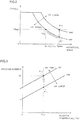
- Fig. 3 is a diagram for illustrating a relation between inverter temperature TW and the current allowed to flow in the inverter. Referring to Fig. 3 , when system voltage VH is constant, generally the current allowed to flow in the inverter increases as inverter temperature TW increases.
- inverter temperature TW When inverter temperature TW is constant, the current allowed to flow in the inverter increases as system voltage VH decreases, since a smaller system voltage causes a smaller surge component of the current that is generated due to a voltage variation.
- system voltage VH1 for changing the state of a point P15 in Fig. 3 to the state of a point P16 in Fig. 3 is determined depending on how much current is to be allowed to flow in the inverter.
- the magnitude of the current flowing in the inverter has a value that is substantially proportional to the magnitude of the current fed from the power storage device.
- system voltage VH1 is determined depending on the magnitude of the current fed from the power storage device.
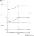
- Fig. 4 is a diagram showing an example of the temperature characteristics of a common power storage device.
- an upper limit Wout of the discharge power is set as shown in Fig. 4 for preventing overdischarge.
- this upper limit Wout of the discharge power as temperature TB of the power storage device becomes smaller than a certain threshold value TB1 and accordingly the internal resistance of the cells in the power storage device increases, the electric power that can be output from the power storage device decreases from a maximum value WoutO.
- a lower limit VBmin of the voltage that is output from each cell in the power storage device generally this lower limit does not depend on the temperature for the sake of preventing degradation of the cells, but is set to a constant value VB0 for example. Therefore, a maximum current IBmax that can be output from the power storage device has a value proportional to upper limit Wout of the discharge power.
- the system voltage is set to the reduced system voltage VH1 without giving consideration to temperature TB of the power storage device.
- the system voltage is set to VH1 under the precondition that maximum current IBmax that can be output from the power storage device has a maximum value IB0 regardless of temperature TB of the power storage device, namely the upper limit of the discharge power is WoutO.
- voltage-setting control is performed at low temperatures in such a manner that system voltage VH is set in consideration of the temperature of the power storage device in addition to the temperature of the inverter. In this way, excessive restriction of system voltage VH can be avoided and thus improved power performance can be expected while the switching elements are protected.
- the system voltage when system voltage VH is to be restricted, the system voltage is set to a smaller system voltage under the precondition that, when a maximum current that can be output by the power storage device flows, the inverter allows the current to flow therein that is supplied to the inverter according to the maximum current.
- upper limit Wout of the discharge power of the power storage device is proportional to maximum current IBmax that can be output by the power storage device. Therefore, in the case where the required electric power output that is calculated from the required torque command and rotational speed at a temperature TB of the power storage device is smaller than upper limit Wout of the discharge power, the output current from the power storage device is smaller than IB0. Thus, the electric power that can be discharged from the power storage device can be restricted to thereby reduce the maximum current that can be output from the power storage device.
- the discharge power of the power storage device can be restricted to thereby reduce the decrease of system voltage VH. Consequently, the rotational speed can be prevented from being limited and therefore deterioration of the power performance can be expected to be suppressed.
- current IAx is calculated that is allowed to flow in the inverter when the current inverter temperature is TA2 and the system voltage is VHx.
- this inverter current IAx is smaller than current IA2 when the system voltage is reduced to VH1.
- Fig. 7 it is determined whether or not output current IBx of the power storage device that corresponds to inverter current IAx calculated in Fig. 6 , when the temperature of the power storage device is TB2, is smaller than maximum current IBmax that can be output at this temperature TB2.
- output current IBx of the power storage device is located at a point P28 in Fig. 7 when the temperature of the power storage device is TB2
- the output current of the power storage device is smaller than maximum current IB0. Therefore, discharge power Woutx corresponding to this current IBx is also smaller than upper limit WoutO of the discharge power at this temperature TB2 (point P29 in Fig. 7 ).
- inverter temperature TW as well as temperature TB of the power storage device at this time are taken into consideration to restrict the electric power that can be output from the power storage device to Woutx when electric power Woutx that is output from the power storage device is smaller than upper limit Wout of the discharge power. In this way, the power performance can be ensured while the switching elements are protected.
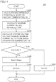
- Fig. 8 is a flowchart for illustrating details of a voltage-setting control process performed by ECU 300 in the first embodiment.
- Each step in the flowchart shown in Fig. 8 and the flowcharts shown in Figs. 14 and 17 and described later herein is implemented by calling a program, which is stored in advance, from a main routine into ECU 300 and executing the program in predetermined cycles. Instead, regarding some of the steps, dedicated hardware (electronic circuitry) may be constructed to implement the steps.
- step S 100 ECU 300 obtains target torques TR1, TR2 of motor generators MG1, MG2 that are calculated based on driver's operation of the accelerator pedal, intake air temperature TAIR of engine 150, and atmospheric pressure PAIR for example.
- ECU 300 uses a map or the like that is stored in advance like the one shown in Fig. 5 to calculate system voltage VHx that enables the obtained target torques TR1, TR2 to be achieved with the maximum rotational speed, for each of motor generators MG1, MG2.
- ECU 300 in S120 calculates, based on a map like the one shown in Fig. 6 , maximum current IAx that is allowed to flow in inverters 131, 135 when the calculated system voltage is VHx at inverter temperatures TW1, TW2. ECU 300 also calculates in S120 current IBx flowing in power storage device 110 that corresponds to current IAx.
- ECU 300 in S130 calculates discharge power Woutx from power storage device 110, based on current IBx and lower limit VB0 of the voltage of power storage device 110.
- ECU 300 determines whether or not discharge power Woutx calculated in S130 based on the map shown in Fig. 7 is smaller than upper limit Wout of the discharge power at temperature TB of power storage device 110.
- Control is thus performed following the above-described process. Therefore, even at low temperatures, when the electric power that is necessary to output a required torque command value with the maximum rotational speed is smaller than the upper limit of the discharge power of the power storage device, the discharge power from the power storage device can be restricted based on respective temperatures of the inverter and the power storage device, to thereby reduce the decrease of system voltage VH. Accordingly, system voltage VH can be reduced without limiting the rotational speed, and therefore, deterioration of the vehicle's power performance can be suppressed while the switching elements are protected.
- system voltage VH may also be set using a multidimensional map including the characteristics of Figs. 5 to 7 and using, as parameters, respective temperatures of the inverter and the power storage device, the required torque command value, and the maximum rotational speed.
- motor generator MG1 functions as an electric generator driven by engine 150 to generate electric power.
- Power split device 140 including the planetary gear train adjusts the torques generated by engine 150 and motor generators MG1, MG2 so that they are balanced.
- Fig. 9 is a nomographic chart showing a relation between respective torques generated by engine 150 and motor generators MG1, MG2.
- the vertical axis of the nomographic chart represents the rotational speed.
- motor generator MG1 is connected to the sun gear of the planetary gear train included in power split device 140, engine 150 is connected to the carrier thereof, and motor generator MG2 is connected to the ring gear thereof.
- adjustments are made based on a ratio m (0 ⁇ m ⁇ 1) defining the reduction ratio, so that torque Te that is output by engine 150 and torque Tg2 that is output by motor generator MG2 are balanced with torque Mg1 generated by motor generator MG1 (line W50 in Fig. 9 ).
- the above-described voltage-setting control can be applied to protect the switching elements and also suppress deterioration of the vehicle's power performance.
- the determination is made using an upper limit of the charge power instead of the above-described upper limit of the discharge power.
- the electric power that is output from power storage device 110 is equal to a difference determined by subtracting the electric power generated by motor generator MG1 from the electric power that is required for generating the drive force by motor generator MG2. It should therefore be noted that, regarding the comparison with upper limit Wout of the discharge power of power storage device 110 in Figs. 7 and 8 , the comparison is made based on the electric power determined by subtracting the electric power generated by motor generator MG1 from the electric power that is necessary for generating a drive force by motor generator MG2.
- the temperature of the power storage device Under low-temperature conditions in which the temperature of the inverter decreases for example, the temperature of the power storage device also decreases in most cases. Therefore, under the condition where the electric power that can be output from the power storage device (upper limit of the discharge power) is restricted like the case where the temperature of the power storage device is lower than threshold value TB1 in Fig. 4 , the maximum current that can be output from the power storage device is also restricted. Accordingly, the current flowing in the inverter is also decreased. In this case, therefore, restriction of system voltage VH may possibly be relaxed, as compared with the case where it is assumed that the maximum current that can be output from the power storage device is IB0 regardless of the temperature of the power storage device.
- Figs. 11 to 13 are diagrams for illustrating voltage-setting control in the second embodiment.
- upper limit Wout of the discharge power of the power storage device at temperature TB of the power storage device is calculated.
- a point P39 at which the value of upper limit Wout of the discharge power is Wouty is calculated.
- maximum current IBmax (IBy) (point P38 in Fig. 11 ) that can be output from the power storage device at this time is calculated from Wouty and lower limit voltage VB0 of the power storage device.
- system voltage VHy* calculated accordingly is smaller than VH1 (point P37 in Fig. 12 ).
- system voltage VH is restricted to more than a required extent. In such a case, the system voltage is therefore set to VH1.
- the voltage-setting control in the second embodiment is effective in the case where upper limit Wout of the discharge power of the power storage device is set smaller than maximum value WoutO as seen from Fig. 11 .
- Fig. 14 is a flowchart for illustrating details of a voltage-setting control process executed by ECU 300.
- ECU 300 calculates maximum current IBy that can be output from power storage device 110, based on discharge power's upper limit Wouty calculated in S200 and lower limit voltage VB0 of power storage device 110. ECU 300 also calculates inverter current IAy corresponding to this maximum current IBy.
- ECU 300 calculates maximum system voltage VHy that enables inverter current IAy calculated as described above to flow, using a map as shown in Fig. 12 . ECU 300 then determines in S230 whether or not calculated system voltage VHy is larger than system voltage VH1 corresponding to the case where the value of discharge power's upper limit Wout of power storage device 110 is maximum value WoutO.
- ECU 300 keeps the value of discharge power's upper limit Wout.
- a multidimensional map including the characteristics in Figs. 11 to 13 may also be used to set system voltage VH.
- Control is thus carried out following the above-described process and therefore, in the case where the discharge power's upper limit of the power storage device is restricted by the temperature of the power storage device, the inverter current is accordingly restricted. This control can therefore be performed to reduce the decrease of the system voltage. In this way, deterioration of the power performance of the vehicle can be suppressed while the switching elements are protected.
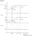
- Figs. 15 and 16 are each a diagram for illustrating voltage-setting control in the third embodiment.
- temperature TB of the power storage device is TB4 for example and the required electric power is PBR (point P49 in Fig. 15 ).
- required electric power PBR is smaller than discharge power's upper limit WoutO at temperature TB4.
- Maximum current IBR that can be output from the power storage device at this time is also smaller than maximum value IB0 at this temperature TB4 (point P48 in Fig. 15 ).
- required electric power PBR when required electric power PBR is smaller than discharge power's upper limit Wout, required electric power PBR is used to restrict the discharge power as done in the first embodiment, so that the decrease of the system voltage can be reduced.
- required electric power PBR when required electric power PBR is larger than discharge power's upper limit Wout, the discharge power can be restricted using the discharge power's upper limit as done in the second embodiment, to thereby reduce the decrease of the system voltage while avoiding overdischarge.
- Fig. 17 is a flowchart for illustrating details of a voltage-setting control process executed by ECU 300.
- ECU 300 in S300 calculates target electric power PBR, based on torque command value TR and target rotational speed NgR.
- ECU 300 in S310 determines whether or not the calculated target electric power PBR is larger than discharge power's upper limit Wout at temperature TB of the power storage device.
- ECU 300 in S360 calculates system voltage VHR that enables above-described current IAR to flow at temperature TW of the inverter. After this, the process returns to the main routine in which target electric power PBR and system voltage VHR are used to generate control signals PWC, PWI1, PWI2 for converter 120 and inverters 131, 135.
- ECU 300 calculates discharge power's upper limit Woutz at temperature TB of power storage device 110, using a map like the one shown in Fig. 15 .
- ECU 300 in S330 calculates maximum current IBz of power storage device 110, from dischargeable power Woutz and voltage's lower limit VB0 of power storage device 110. ECU 300 also calculates inverter current IAz corresponding to this current IBz.
- the required electric power, the temperature of the power storage device, and the temperature of the inverter may be used as parameters and a multidimensional map including the characteristics in Figs. 15 and 16 may be used to set system voltage VH.
- the control can be carried out following the above-described process to set the system voltage based on the actual required electric power, in consideration of respective temperatures of the power storage device and the inverter. In this way, deterioration of the vehicle's power performance can be suppressed while the switching elements are protected.
- the above-described voltage-setting control processes may be applied to power storage device 110 in the charging state.
Landscapes
- Engineering & Computer Science (AREA)
- Power Engineering (AREA)
- Transportation (AREA)
- Mechanical Engineering (AREA)
- Life Sciences & Earth Sciences (AREA)
- Sustainable Development (AREA)
- Sustainable Energy (AREA)
- Electric Propulsion And Braking For Vehicles (AREA)
- Dc-Dc Converters (AREA)
Applications Claiming Priority (1)
| Application Number | Priority Date | Filing Date | Title |
|---|---|---|---|
| PCT/JP2010/058424 WO2011145184A1 (ja) | 2010-05-19 | 2010-05-19 | 車両 |
Publications (3)
| Publication Number | Publication Date |
|---|---|
| EP2471682A1 EP2471682A1 (en) | 2012-07-04 |
| EP2471682A4 EP2471682A4 (en) | 2017-10-25 |
| EP2471682B1 true EP2471682B1 (en) | 2019-12-18 |
Family
ID=44991308
Family Applications (1)
| Application Number | Title | Priority Date | Filing Date |
|---|---|---|---|
| EP10851748.3A Active EP2471682B1 (en) | 2010-05-19 | 2010-05-19 | Vehicle |
Country Status (5)
| Country | Link |
|---|---|
| US (1) | US8674637B2 (ja) |
| EP (1) | EP2471682B1 (ja) |
| JP (1) | JP5029793B2 (ja) |
| CN (1) | CN102892616B (ja) |
| WO (1) | WO2011145184A1 (ja) |
Families Citing this family (21)
| Publication number | Priority date | Publication date | Assignee | Title |
|---|---|---|---|---|
| EP2680434B1 (en) * | 2011-02-25 | 2020-09-30 | NTN Corporation | Electric automobile |
| DE102011084230A1 (de) * | 2011-10-10 | 2013-04-11 | Robert Bosch Gmbh | Verfahren zum Betreiben eines Umsetzers für einen Startermotor |
| CN103042927B (zh) * | 2012-12-17 | 2015-11-18 | 联合汽车电子有限公司 | 一种新能源汽车的拖车保护电路及其实现方法 |
| JP5742879B2 (ja) * | 2013-05-21 | 2015-07-01 | トヨタ自動車株式会社 | 車両用の回転電機の制御装置 |
| FR3007699B1 (fr) * | 2013-07-01 | 2018-06-29 | Renault Sas | Procede de commande d'un groupe motopropulseur electrique optimisant la phase d'utilisation a faible vitesse |
| JP6361559B2 (ja) * | 2014-06-20 | 2018-07-25 | トヨタ自動車株式会社 | 車両の制御装置 |
| US9878632B2 (en) * | 2014-08-19 | 2018-01-30 | General Electric Company | Vehicle propulsion system having an energy storage system and optimized method of controlling operation thereof |
| JP6484436B2 (ja) * | 2014-11-19 | 2019-03-13 | 日立オートモティブシステムズ株式会社 | インバータ制御装置 |
| JP6160601B2 (ja) * | 2014-12-02 | 2017-07-12 | トヨタ自動車株式会社 | 電源システム |
| GB201421791D0 (en) * | 2014-12-08 | 2015-01-21 | Trw Ltd | Method and apparatus for controlling and electric pump of a hydraulic braking circuit |
| JP6443253B2 (ja) * | 2015-07-24 | 2018-12-26 | 株式会社デンソー | 電力変換器制御装置 |
| US9768719B2 (en) * | 2015-09-18 | 2017-09-19 | Faraday&Future Inc. | Methods and apparatus for generating current commands for an interior permanent magnet (IPM) motor |
| US9762164B2 (en) * | 2015-09-18 | 2017-09-12 | Faraday & Future Inc. | Methods and apparatus for generating current commands for an interior permanent magnet (IPM) motor |
| WO2017099655A1 (en) * | 2015-12-08 | 2017-06-15 | Scania Cv Ab | A method and a system for controlling an output torque of an electric machine in a vehicle |
| JP6299738B2 (ja) * | 2015-12-24 | 2018-03-28 | トヨタ自動車株式会社 | 非接触送電装置及び電力伝送システム |
| JP6409027B2 (ja) * | 2016-07-07 | 2018-10-17 | 株式会社豊田中央研究所 | 電力変換装置 |
| EP3793083B1 (en) * | 2018-05-10 | 2023-02-15 | Nissan Motor Co., Ltd. | Control method for motor system, and control device for motor system |
| DE102018123206A1 (de) * | 2018-09-20 | 2020-03-26 | Valeo Siemens Eautomotive Germany Gmbh | Steuerungseinrichtung für einen Wechselrichter, Wechselrichter für eine Asynchronmaschine, Fahrzeug und Verfahren zum Betreiben eines Wechselrichters |
| EP4002664A1 (en) * | 2020-11-11 | 2022-05-25 | Valeo Siemens eAutomotive Germany GmbH | Inverter, method for configuring an inverter, method for controlling an inverter and corresponding computer program |
| DE102020130993A1 (de) * | 2020-11-24 | 2022-05-25 | Audi Aktiengesellschaft | Verfahren zum Ermitteln eines Maximalwerts für einen Parameterbereich eines Fahrbetriebsparameters eines Kraftfahrzeugs und Kraftfahrzeug |
| CN117246148A (zh) * | 2023-11-01 | 2023-12-19 | 采埃孚传动技术(嘉兴)有限公司 | 电驱动系统的控制方法、控制装置、电子设备和存储介质 |
Family Cites Families (18)
| Publication number | Priority date | Publication date | Assignee | Title |
|---|---|---|---|---|
| JP3415326B2 (ja) * | 1995-04-28 | 2003-06-09 | 株式会社デンソー | 車両用発電機の出力制御装置 |
| US5731689A (en) * | 1995-06-06 | 1998-03-24 | Nippondenso Co., Ltd. | Control system for A.C. generator |
| JP3328509B2 (ja) * | 1996-05-29 | 2002-09-24 | 株式会社日立製作所 | 電気車用駆動システム |
| JP2006025493A (ja) | 2004-07-06 | 2006-01-26 | Toyota Motor Corp | 電力変換装置およびその電流制限方法 |
| JP2006149064A (ja) | 2004-11-18 | 2006-06-08 | Toyota Motor Corp | 車両駆動システムおよびそれを備える車両 |
| JP4665809B2 (ja) * | 2006-03-24 | 2011-04-06 | トヨタ自動車株式会社 | 電動機駆動制御システム |
| JP4462243B2 (ja) * | 2006-07-10 | 2010-05-12 | トヨタ自動車株式会社 | 負荷駆動装置およびそれを備える車両 |
| JP4155321B2 (ja) * | 2006-09-25 | 2008-09-24 | トヨタ自動車株式会社 | ハイブリッド車両の表示装置、ハイブリッド車両、およびハイブリッド車両の表示方法 |
| JP4678374B2 (ja) * | 2007-01-04 | 2011-04-27 | トヨタ自動車株式会社 | 負荷装置の制御装置、および車両 |
| JP5067098B2 (ja) | 2007-09-26 | 2012-11-07 | 株式会社デンソー | 昇降圧コンバータの制御装置 |
| JP2009113706A (ja) * | 2007-11-08 | 2009-05-28 | Toyota Motor Corp | ハイブリッド車両 |
| JP4525765B2 (ja) * | 2008-02-08 | 2010-08-18 | 株式会社デンソー | 車両システム |
| JP5211743B2 (ja) | 2008-02-19 | 2013-06-12 | トヨタ自動車株式会社 | 電源装置、それを搭載する車両および電源装置の制御方法 |
| JP4670882B2 (ja) * | 2008-03-18 | 2011-04-13 | トヨタ自動車株式会社 | 電動機駆動制御装置、それを備えた車両および電動機駆動制御方法 |
| JP2009227080A (ja) | 2008-03-21 | 2009-10-08 | Toyota Motor Corp | 動力出力装置やこれを備える車両および駆動装置並びにこれらの制御方法 |
| JP2009240087A (ja) * | 2008-03-27 | 2009-10-15 | Hitachi Ltd | 回転電機の制御装置 |
| US8575897B2 (en) * | 2008-10-03 | 2013-11-05 | Denso Corporation | Battery temperature control system |
| JP5288170B2 (ja) * | 2008-10-03 | 2013-09-11 | 株式会社デンソー | バッテリの昇温制御装置 |
-
2010
- 2010-05-19 JP JP2012515670A patent/JP5029793B2/ja active Active
- 2010-05-19 CN CN201080066856.9A patent/CN102892616B/zh active Active
- 2010-05-19 WO PCT/JP2010/058424 patent/WO2011145184A1/ja active Application Filing
- 2010-05-19 EP EP10851748.3A patent/EP2471682B1/en active Active
- 2010-05-19 US US13/497,008 patent/US8674637B2/en active Active
Non-Patent Citations (1)
| Title |
|---|
| None * |
Also Published As
| Publication number | Publication date |
|---|---|
| EP2471682A4 (en) | 2017-10-25 |
| US20120175948A1 (en) | 2012-07-12 |
| CN102892616B (zh) | 2014-08-13 |
| US8674637B2 (en) | 2014-03-18 |
| JPWO2011145184A1 (ja) | 2013-07-22 |
| WO2011145184A1 (ja) | 2011-11-24 |
| EP2471682A1 (en) | 2012-07-04 |
| CN102892616A (zh) | 2013-01-23 |
| JP5029793B2 (ja) | 2012-09-19 |
Similar Documents
| Publication | Publication Date | Title |
|---|---|---|
| EP2471682B1 (en) | Vehicle | |
| CN101803147B (zh) | 蓄电装置的充电控制装置以及充电控制方法 | |
| JP4793237B2 (ja) | 二次電池の充放電制御装置、および、それを備える車両 | |
| US11097624B2 (en) | Driving system | |
| JP5024454B2 (ja) | 電動車両の電源システムおよびその制御方法 | |
| US8624426B2 (en) | Power supply system for electrically powered vehicle, electrically powered vehicle, and method for controlling power supply system of electrically powered vehicle | |
| CN101432175B (zh) | 内燃机的停止控制装置以及停止控制方法 | |
| CN102307746B (zh) | 电源系统以及具备该电源系统的电动车辆 | |
| US8538616B2 (en) | Power supply system for electrically powered vehicle, electrically powered vehicle, and method for controlling the same | |
| CN101535082B (zh) | 电动车辆及电压变换装置的控制方法 | |
| US8565953B2 (en) | Hybrid vehicle and method for controlling the same | |
| JP5660102B2 (ja) | 車両の電源装置 | |
| JP5716694B2 (ja) | 電動車両 | |
| WO2010143277A1 (ja) | 電動車両の電源システムおよびその制御方法 | |
| JP5228824B2 (ja) | 車両の電源システムおよび車両 | |
| JP2010098844A (ja) | 車両の電源システム | |
| JP2009027812A (ja) | 車両の電源装置 | |
| JP5227230B2 (ja) | 電動車両 | |
| JP2013192278A (ja) | 電動車両 | |
| JP2007274785A (ja) | 車両駆動用電源システム | |
| JP2010136553A (ja) | 電源システムおよびそれを搭載した電動車両 | |
| JP2009171766A (ja) | 車両駆動システムおよびそれを備える車両 | |
| JP5718660B2 (ja) | 車両および車両の制御方法 | |
| JP2010115050A (ja) | 車両の電源システム | |
| JP4948329B2 (ja) | モータ駆動装置およびモータ駆動装置の制御方法 |
Legal Events
| Date | Code | Title | Description |
|---|---|---|---|
| PUAI | Public reference made under article 153(3) epc to a published international application that has entered the european phase |
Free format text: ORIGINAL CODE: 0009012 |
|
| 17P | Request for examination filed |
Effective date: 20120328 |
|
| AK | Designated contracting states |
Kind code of ref document: A1 Designated state(s): AL AT BE BG CH CY CZ DE DK EE ES FI FR GB GR HR HU IE IS IT LI LT LU LV MC MK MT NL NO PL PT RO SE SI SK SM TR |
|
| RAP1 | Party data changed (applicant data changed or rights of an application transferred) |
Owner name: TOYOTA JIDOSHA KABUSHIKI KAISHA |
|
| DAX | Request for extension of the european patent (deleted) | ||
| RA4 | Supplementary search report drawn up and despatched (corrected) |
Effective date: 20170922 |
|
| RIC1 | Information provided on ipc code assigned before grant |
Ipc: B60L 3/12 20060101ALI20170918BHEP Ipc: H02P 29/68 20160101ALI20170918BHEP Ipc: H02P 29/02 20160101ALI20170918BHEP Ipc: H02M 3/155 20060101ALI20170918BHEP Ipc: B60L 11/18 20060101AFI20170918BHEP Ipc: H02M 1/32 20070101ALI20170918BHEP Ipc: H02M 7/48 20070101ALI20170918BHEP |
|
| STAA | Information on the status of an ep patent application or granted ep patent |
Free format text: STATUS: EXAMINATION IS IN PROGRESS |
|
| 17Q | First examination report despatched |
Effective date: 20181105 |
|
| RIC1 | Information provided on ipc code assigned before grant |
Ipc: H02P 29/02 20160101ALI20170918BHEP Ipc: H02M 3/155 20060101ALI20170918BHEP Ipc: B60L 3/12 20060101ALI20170918BHEP Ipc: H02P 29/68 20160101ALI20170918BHEP Ipc: H02M 7/48 20070101ALI20170918BHEP Ipc: H02M 1/32 20070101ALI20170918BHEP Ipc: B60L 11/18 20060101AFI20170918BHEP |
|
| REG | Reference to a national code |
Ref country code: DE Ref legal event code: R079 Ref document number: 602010062462 Country of ref document: DE Free format text: PREVIOUS MAIN CLASS: B60L0011180000 Ipc: B60L0050500000 |
|
| RIC1 | Information provided on ipc code assigned before grant |
Ipc: B60L 3/12 20060101ALI20190426BHEP Ipc: B60L 50/50 20190101AFI20190426BHEP Ipc: H02M 1/32 20070101ALI20190426BHEP Ipc: H02P 29/02 20160101ALI20190426BHEP Ipc: H02P 29/68 20160101ALI20190426BHEP Ipc: H02M 3/155 20060101ALI20190426BHEP Ipc: H02M 7/48 20070101ALI20190426BHEP |
|
| GRAJ | Information related to disapproval of communication of intention to grant by the applicant or resumption of examination proceedings by the epo deleted |
Free format text: ORIGINAL CODE: EPIDOSDIGR1 |
|
| STAA | Information on the status of an ep patent application or granted ep patent |
Free format text: STATUS: GRANT OF PATENT IS INTENDED |
|
| GRAP | Despatch of communication of intention to grant a patent |
Free format text: ORIGINAL CODE: EPIDOSNIGR1 |
|
| INTG | Intention to grant announced |
Effective date: 20190708 |
|
| RIN1 | Information on inventor provided before grant (corrected) |
Inventor name: KAMIJO, YUSUKE |
|
| GRAS | Grant fee paid |
Free format text: ORIGINAL CODE: EPIDOSNIGR3 |
|
| GRAA | (expected) grant |
Free format text: ORIGINAL CODE: 0009210 |
|
| STAA | Information on the status of an ep patent application or granted ep patent |
Free format text: STATUS: THE PATENT HAS BEEN GRANTED |
|
| AK | Designated contracting states |
Kind code of ref document: B1 Designated state(s): AL AT BE BG CH CY CZ DE DK EE ES FI FR GB GR HR HU IE IS IT LI LT LU LV MC MK MT NL NO PL PT RO SE SI SK SM TR |
|
| REG | Reference to a national code |
Ref country code: GB Ref legal event code: FG4D |
|
| REG | Reference to a national code |
Ref country code: CH Ref legal event code: EP |
|
| REG | Reference to a national code |
Ref country code: IE Ref legal event code: FG4D |
|
| REG | Reference to a national code |
Ref country code: DE Ref legal event code: R096 Ref document number: 602010062462 Country of ref document: DE |
|
| REG | Reference to a national code |
Ref country code: AT Ref legal event code: REF Ref document number: 1214214 Country of ref document: AT Kind code of ref document: T Effective date: 20200115 |
|
| REG | Reference to a national code |
Ref country code: NL Ref legal event code: MP Effective date: 20191218 |
|
| PG25 | Lapsed in a contracting state [announced via postgrant information from national office to epo] |
Ref country code: LV Free format text: LAPSE BECAUSE OF FAILURE TO SUBMIT A TRANSLATION OF THE DESCRIPTION OR TO PAY THE FEE WITHIN THE PRESCRIBED TIME-LIMIT Effective date: 20191218 Ref country code: SE Free format text: LAPSE BECAUSE OF FAILURE TO SUBMIT A TRANSLATION OF THE DESCRIPTION OR TO PAY THE FEE WITHIN THE PRESCRIBED TIME-LIMIT Effective date: 20191218 Ref country code: LT Free format text: LAPSE BECAUSE OF FAILURE TO SUBMIT A TRANSLATION OF THE DESCRIPTION OR TO PAY THE FEE WITHIN THE PRESCRIBED TIME-LIMIT Effective date: 20191218 Ref country code: GR Free format text: LAPSE BECAUSE OF FAILURE TO SUBMIT A TRANSLATION OF THE DESCRIPTION OR TO PAY THE FEE WITHIN THE PRESCRIBED TIME-LIMIT Effective date: 20200319 Ref country code: NO Free format text: LAPSE BECAUSE OF FAILURE TO SUBMIT A TRANSLATION OF THE DESCRIPTION OR TO PAY THE FEE WITHIN THE PRESCRIBED TIME-LIMIT Effective date: 20200318 Ref country code: FI Free format text: LAPSE BECAUSE OF FAILURE TO SUBMIT A TRANSLATION OF THE DESCRIPTION OR TO PAY THE FEE WITHIN THE PRESCRIBED TIME-LIMIT Effective date: 20191218 Ref country code: BG Free format text: LAPSE BECAUSE OF FAILURE TO SUBMIT A TRANSLATION OF THE DESCRIPTION OR TO PAY THE FEE WITHIN THE PRESCRIBED TIME-LIMIT Effective date: 20200318 |
|
| REG | Reference to a national code |
Ref country code: LT Ref legal event code: MG4D |
|
| PG25 | Lapsed in a contracting state [announced via postgrant information from national office to epo] |
Ref country code: HR Free format text: LAPSE BECAUSE OF FAILURE TO SUBMIT A TRANSLATION OF THE DESCRIPTION OR TO PAY THE FEE WITHIN THE PRESCRIBED TIME-LIMIT Effective date: 20191218 |
|
| PG25 | Lapsed in a contracting state [announced via postgrant information from national office to epo] |
Ref country code: AL Free format text: LAPSE BECAUSE OF FAILURE TO SUBMIT A TRANSLATION OF THE DESCRIPTION OR TO PAY THE FEE WITHIN THE PRESCRIBED TIME-LIMIT Effective date: 20191218 |
|
| PG25 | Lapsed in a contracting state [announced via postgrant information from national office to epo] |
Ref country code: NL Free format text: LAPSE BECAUSE OF FAILURE TO SUBMIT A TRANSLATION OF THE DESCRIPTION OR TO PAY THE FEE WITHIN THE PRESCRIBED TIME-LIMIT Effective date: 20191218 Ref country code: RO Free format text: LAPSE BECAUSE OF FAILURE TO SUBMIT A TRANSLATION OF THE DESCRIPTION OR TO PAY THE FEE WITHIN THE PRESCRIBED TIME-LIMIT Effective date: 20191218 Ref country code: EE Free format text: LAPSE BECAUSE OF FAILURE TO SUBMIT A TRANSLATION OF THE DESCRIPTION OR TO PAY THE FEE WITHIN THE PRESCRIBED TIME-LIMIT Effective date: 20191218 Ref country code: CZ Free format text: LAPSE BECAUSE OF FAILURE TO SUBMIT A TRANSLATION OF THE DESCRIPTION OR TO PAY THE FEE WITHIN THE PRESCRIBED TIME-LIMIT Effective date: 20191218 Ref country code: PT Free format text: LAPSE BECAUSE OF FAILURE TO SUBMIT A TRANSLATION OF THE DESCRIPTION OR TO PAY THE FEE WITHIN THE PRESCRIBED TIME-LIMIT Effective date: 20200513 |
|
| PG25 | Lapsed in a contracting state [announced via postgrant information from national office to epo] |
Ref country code: SM Free format text: LAPSE BECAUSE OF FAILURE TO SUBMIT A TRANSLATION OF THE DESCRIPTION OR TO PAY THE FEE WITHIN THE PRESCRIBED TIME-LIMIT Effective date: 20191218 Ref country code: SK Free format text: LAPSE BECAUSE OF FAILURE TO SUBMIT A TRANSLATION OF THE DESCRIPTION OR TO PAY THE FEE WITHIN THE PRESCRIBED TIME-LIMIT Effective date: 20191218 Ref country code: IS Free format text: LAPSE BECAUSE OF FAILURE TO SUBMIT A TRANSLATION OF THE DESCRIPTION OR TO PAY THE FEE WITHIN THE PRESCRIBED TIME-LIMIT Effective date: 20200418 |
|
| REG | Reference to a national code |
Ref country code: DE Ref legal event code: R097 Ref document number: 602010062462 Country of ref document: DE |
|
| REG | Reference to a national code |
Ref country code: AT Ref legal event code: MK05 Ref document number: 1214214 Country of ref document: AT Kind code of ref document: T Effective date: 20191218 |
|
| PLBE | No opposition filed within time limit |
Free format text: ORIGINAL CODE: 0009261 |
|
| STAA | Information on the status of an ep patent application or granted ep patent |
Free format text: STATUS: NO OPPOSITION FILED WITHIN TIME LIMIT |
|
| PG25 | Lapsed in a contracting state [announced via postgrant information from national office to epo] |
Ref country code: DK Free format text: LAPSE BECAUSE OF FAILURE TO SUBMIT A TRANSLATION OF THE DESCRIPTION OR TO PAY THE FEE WITHIN THE PRESCRIBED TIME-LIMIT Effective date: 20191218 Ref country code: ES Free format text: LAPSE BECAUSE OF FAILURE TO SUBMIT A TRANSLATION OF THE DESCRIPTION OR TO PAY THE FEE WITHIN THE PRESCRIBED TIME-LIMIT Effective date: 20191218 |
|
| 26N | No opposition filed |
Effective date: 20200921 |
|
| PG25 | Lapsed in a contracting state [announced via postgrant information from national office to epo] |
Ref country code: AT Free format text: LAPSE BECAUSE OF FAILURE TO SUBMIT A TRANSLATION OF THE DESCRIPTION OR TO PAY THE FEE WITHIN THE PRESCRIBED TIME-LIMIT Effective date: 20191218 Ref country code: SI Free format text: LAPSE BECAUSE OF FAILURE TO SUBMIT A TRANSLATION OF THE DESCRIPTION OR TO PAY THE FEE WITHIN THE PRESCRIBED TIME-LIMIT Effective date: 20191218 |
|
| PG25 | Lapsed in a contracting state [announced via postgrant information from national office to epo] |
Ref country code: CH Free format text: LAPSE BECAUSE OF NON-PAYMENT OF DUE FEES Effective date: 20200531 Ref country code: MC Free format text: LAPSE BECAUSE OF FAILURE TO SUBMIT A TRANSLATION OF THE DESCRIPTION OR TO PAY THE FEE WITHIN THE PRESCRIBED TIME-LIMIT Effective date: 20191218 Ref country code: IT Free format text: LAPSE BECAUSE OF FAILURE TO SUBMIT A TRANSLATION OF THE DESCRIPTION OR TO PAY THE FEE WITHIN THE PRESCRIBED TIME-LIMIT Effective date: 20191218 Ref country code: LI Free format text: LAPSE BECAUSE OF NON-PAYMENT OF DUE FEES Effective date: 20200531 |
|
| PG25 | Lapsed in a contracting state [announced via postgrant information from national office to epo] |
Ref country code: PL Free format text: LAPSE BECAUSE OF FAILURE TO SUBMIT A TRANSLATION OF THE DESCRIPTION OR TO PAY THE FEE WITHIN THE PRESCRIBED TIME-LIMIT Effective date: 20191218 |
|
| REG | Reference to a national code |
Ref country code: BE Ref legal event code: MM Effective date: 20200531 |
|
| PG25 | Lapsed in a contracting state [announced via postgrant information from national office to epo] |
Ref country code: LU Free format text: LAPSE BECAUSE OF NON-PAYMENT OF DUE FEES Effective date: 20200519 |
|
| PG25 | Lapsed in a contracting state [announced via postgrant information from national office to epo] |
Ref country code: IE Free format text: LAPSE BECAUSE OF NON-PAYMENT OF DUE FEES Effective date: 20200519 |
|
| PG25 | Lapsed in a contracting state [announced via postgrant information from national office to epo] |
Ref country code: BE Free format text: LAPSE BECAUSE OF NON-PAYMENT OF DUE FEES Effective date: 20200531 |
|
| PG25 | Lapsed in a contracting state [announced via postgrant information from national office to epo] |
Ref country code: TR Free format text: LAPSE BECAUSE OF FAILURE TO SUBMIT A TRANSLATION OF THE DESCRIPTION OR TO PAY THE FEE WITHIN THE PRESCRIBED TIME-LIMIT Effective date: 20191218 Ref country code: MT Free format text: LAPSE BECAUSE OF FAILURE TO SUBMIT A TRANSLATION OF THE DESCRIPTION OR TO PAY THE FEE WITHIN THE PRESCRIBED TIME-LIMIT Effective date: 20191218 Ref country code: CY Free format text: LAPSE BECAUSE OF FAILURE TO SUBMIT A TRANSLATION OF THE DESCRIPTION OR TO PAY THE FEE WITHIN THE PRESCRIBED TIME-LIMIT Effective date: 20191218 |
|
| PG25 | Lapsed in a contracting state [announced via postgrant information from national office to epo] |
Ref country code: MK Free format text: LAPSE BECAUSE OF FAILURE TO SUBMIT A TRANSLATION OF THE DESCRIPTION OR TO PAY THE FEE WITHIN THE PRESCRIBED TIME-LIMIT Effective date: 20191218 |
|
| REG | Reference to a national code |
Ref country code: FR Ref legal event code: PLFP Year of fee payment: 14 |
|
| PGFP | Annual fee paid to national office [announced via postgrant information from national office to epo] |
Ref country code: GB Payment date: 20230330 Year of fee payment: 14 |
|
| P01 | Opt-out of the competence of the unified patent court (upc) registered |
Effective date: 20230427 |
|
| REG | Reference to a national code |
Ref country code: DE Ref legal event code: R084 Ref document number: 602010062462 Country of ref document: DE |
|
| PGFP | Annual fee paid to national office [announced via postgrant information from national office to epo] |
Ref country code: FR Payment date: 20230411 Year of fee payment: 14 Ref country code: DE Payment date: 20230331 Year of fee payment: 14 |
|
| REG | Reference to a national code |
Ref country code: GB Ref legal event code: 746 Effective date: 20230815 |