EP2469296B1 - Capteur optoélectronique et procédé destiné à la détection et la détermination de l'éloignement d'objets - Google Patents
Capteur optoélectronique et procédé destiné à la détection et la détermination de l'éloignement d'objets Download PDFInfo
- Publication number
- EP2469296B1 EP2469296B1 EP11184192A EP11184192A EP2469296B1 EP 2469296 B1 EP2469296 B1 EP 2469296B1 EP 11184192 A EP11184192 A EP 11184192A EP 11184192 A EP11184192 A EP 11184192A EP 2469296 B1 EP2469296 B1 EP 2469296B1
- Authority
- EP
- European Patent Office
- Prior art keywords
- pulses
- histogram
- angular position
- sensor
- group
- Prior art date
- Legal status (The legal status is an assumption and is not a legal conclusion. Google has not performed a legal analysis and makes no representation as to the accuracy of the status listed.)
- Active
Links
- 238000000034 method Methods 0.000 title claims description 31
- 230000005693 optoelectronics Effects 0.000 title claims description 7
- 238000011156 evaluation Methods 0.000 claims description 75
- 238000005259 measurement Methods 0.000 claims description 48
- 238000001514 detection method Methods 0.000 claims description 22
- 230000005540 biological transmission Effects 0.000 claims description 20
- 238000012544 monitoring process Methods 0.000 claims description 20
- 230000011514 reflex Effects 0.000 claims description 5
- 230000000670 limiting effect Effects 0.000 claims description 4
- 238000012360 testing method Methods 0.000 claims description 2
- 230000000737 periodic effect Effects 0.000 claims 2
- 238000012935 Averaging Methods 0.000 description 11
- 230000001681 protective effect Effects 0.000 description 7
- 230000002123 temporal effect Effects 0.000 description 7
- 230000002829 reductive effect Effects 0.000 description 6
- 230000003287 optical effect Effects 0.000 description 5
- 230000036316 preload Effects 0.000 description 5
- 230000006870 function Effects 0.000 description 4
- 238000007781 pre-processing Methods 0.000 description 4
- 238000010972 statistical evaluation Methods 0.000 description 4
- 230000003044 adaptive effect Effects 0.000 description 3
- 230000003111 delayed effect Effects 0.000 description 3
- 230000001419 dependent effect Effects 0.000 description 3
- 238000005516 engineering process Methods 0.000 description 3
- 230000000694 effects Effects 0.000 description 2
- 230000007613 environmental effect Effects 0.000 description 2
- 238000012545 processing Methods 0.000 description 2
- 230000003068 static effect Effects 0.000 description 2
- 230000006978 adaptation Effects 0.000 description 1
- 230000004888 barrier function Effects 0.000 description 1
- 230000006399 behavior Effects 0.000 description 1
- 238000006243 chemical reaction Methods 0.000 description 1
- 238000011109 contamination Methods 0.000 description 1
- 230000003247 decreasing effect Effects 0.000 description 1
- 238000013461 design Methods 0.000 description 1
- 238000010586 diagram Methods 0.000 description 1
- 238000013213 extrapolation Methods 0.000 description 1
- 238000005286 illumination Methods 0.000 description 1
- 238000004519 manufacturing process Methods 0.000 description 1
- 238000000691 measurement method Methods 0.000 description 1
- 238000001208 nuclear magnetic resonance pulse sequence Methods 0.000 description 1
- 230000010355 oscillation Effects 0.000 description 1
- 230000010363 phase shift Effects 0.000 description 1
- 238000000053 physical method Methods 0.000 description 1
- 230000004044 response Effects 0.000 description 1
- 238000012552 review Methods 0.000 description 1
- 230000035945 sensitivity Effects 0.000 description 1
- 238000011895 specific detection Methods 0.000 description 1
- 230000001629 suppression Effects 0.000 description 1
- 238000012549 training Methods 0.000 description 1
- 238000011144 upstream manufacturing Methods 0.000 description 1
Images


Classifications
-
- G—PHYSICS
- G01—MEASURING; TESTING
- G01C—MEASURING DISTANCES, LEVELS OR BEARINGS; SURVEYING; NAVIGATION; GYROSCOPIC INSTRUMENTS; PHOTOGRAMMETRY OR VIDEOGRAMMETRY
- G01C3/00—Measuring distances in line of sight; Optical rangefinders
- G01C3/02—Details
- G01C3/06—Use of electric means to obtain final indication
- G01C3/08—Use of electric radiation detectors
-
- G—PHYSICS
- G01—MEASURING; TESTING
- G01S—RADIO DIRECTION-FINDING; RADIO NAVIGATION; DETERMINING DISTANCE OR VELOCITY BY USE OF RADIO WAVES; LOCATING OR PRESENCE-DETECTING BY USE OF THE REFLECTION OR RERADIATION OF RADIO WAVES; ANALOGOUS ARRANGEMENTS USING OTHER WAVES
- G01S7/00—Details of systems according to groups G01S13/00, G01S15/00, G01S17/00
- G01S7/48—Details of systems according to groups G01S13/00, G01S15/00, G01S17/00 of systems according to group G01S17/00
- G01S7/481—Constructional features, e.g. arrangements of optical elements
- G01S7/4817—Constructional features, e.g. arrangements of optical elements relating to scanning
-
- G—PHYSICS
- G01—MEASURING; TESTING
- G01S—RADIO DIRECTION-FINDING; RADIO NAVIGATION; DETERMINING DISTANCE OR VELOCITY BY USE OF RADIO WAVES; LOCATING OR PRESENCE-DETECTING BY USE OF THE REFLECTION OR RERADIATION OF RADIO WAVES; ANALOGOUS ARRANGEMENTS USING OTHER WAVES
- G01S17/00—Systems using the reflection or reradiation of electromagnetic waves other than radio waves, e.g. lidar systems
- G01S17/02—Systems using the reflection of electromagnetic waves other than radio waves
- G01S17/06—Systems determining position data of a target
- G01S17/42—Simultaneous measurement of distance and other co-ordinates
-
- G—PHYSICS
- G01—MEASURING; TESTING
- G01S—RADIO DIRECTION-FINDING; RADIO NAVIGATION; DETERMINING DISTANCE OR VELOCITY BY USE OF RADIO WAVES; LOCATING OR PRESENCE-DETECTING BY USE OF THE REFLECTION OR RERADIATION OF RADIO WAVES; ANALOGOUS ARRANGEMENTS USING OTHER WAVES
- G01S7/00—Details of systems according to groups G01S13/00, G01S15/00, G01S17/00
- G01S7/48—Details of systems according to groups G01S13/00, G01S15/00, G01S17/00 of systems according to group G01S17/00
- G01S7/483—Details of pulse systems
- G01S7/486—Receivers
- G01S7/4861—Circuits for detection, sampling, integration or read-out
-
- G—PHYSICS
- G01—MEASURING; TESTING
- G01S—RADIO DIRECTION-FINDING; RADIO NAVIGATION; DETERMINING DISTANCE OR VELOCITY BY USE OF RADIO WAVES; LOCATING OR PRESENCE-DETECTING BY USE OF THE REFLECTION OR RERADIATION OF RADIO WAVES; ANALOGOUS ARRANGEMENTS USING OTHER WAVES
- G01S7/00—Details of systems according to groups G01S13/00, G01S15/00, G01S17/00
- G01S7/48—Details of systems according to groups G01S13/00, G01S15/00, G01S17/00 of systems according to group G01S17/00
- G01S7/483—Details of pulse systems
- G01S7/486—Receivers
- G01S7/487—Extracting wanted echo signals, e.g. pulse detection
- G01S7/4876—Extracting wanted echo signals, e.g. pulse detection by removing unwanted signals
Definitions
- the invention relates to an optoelectronic sensor, in particular a laser scanner, and to a method for detecting and determining the distance of objects according to the preamble of claims 1 and 15, respectively.
- a laser scanner For distance measurements that require a large horizontal angle range of the measuring system, optoelectronic systems and especially laser scanners are suitable.
- a laser beam generated by a laser periodically sweeps over a monitoring area by means of a deflection unit. The light is remitted to objects in the surveillance area and evaluated in the scanner. From the angular position of the deflection is on the angular position of the object and from the light transit time using the speed of light in addition to the removal of the object from the laser scanner closed.
- the location of an object in the surveillance area is recorded in two-dimensional polar coordinates.
- the third spatial coordinate can also be detected by a relative movement in the transverse direction, for example by a further degree of freedom of movement of the deflection unit in the laser scanner or by the object being transported relative to the laser scanner.
- a relative movement in the transverse direction for example by a further degree of freedom of movement of the deflection unit in the laser scanner or by the object being transported relative to the laser scanner.
- laser scanners are also used in security technology to monitor a source of danger, such as a dangerous machine.
- a safety laser scanner is from the DE 43 40 756 A1 known.
- a protective field is monitored during operation The machine may not be entered by the operating personnel. If the laser scanner detects an inadmissible protective field intervention, for example a leg of an operator, it triggers an emergency stop of the machine. Other interference with the protective field, for example due to static machine parts, can be taught in advance as permissible.
- the protective fields are preceded by warning fields, where interventions initially only lead to a warning in order to prevent the interception of the protective field and thus the protection in good time, thus increasing the availability of the system.
- Safety laser scanners usually work pulse-based.
- Sensors used in safety technology must work extremely reliably and therefore meet high safety requirements, for example the EN13849 standard for machine safety and the EN61496 device standard for non-contact protective devices (ESPE).
- ESE non-contact protective devices
- a number of measures must be taken, such as secure electronic evaluation by redundant, diverse electronics, function monitoring or specially monitoring the contamination of optical components, in particular a windscreen, and / or providing individual test objectives with defined degrees of reflection, among the corresponding Scan angles must be detected.
- phase-based methods the continuous transmitted light is modulated and the phase shift of the received light compared to the transmitted light is evaluated.
- pulse-based methods or pulse transit time methods the transmitter operates in a single-pulse mode with relatively high pulse energies, and the laser scanner measures object distances based on the transit time between the transmission and reception of a single-light pulse.
- a disadvantage of a pulse transit time method is that, as a rule, a large transmission power and a very sensitive receiver must be available in order to achieve a significant measuring range.
- a phase-based method with modulation of a continuous wave or CW laser in turn has the disadvantage that it offers only a limited uniqueness range of typically a few meters.
- the optical output power of the transmitter is usually low in this method, so that especially with additional external influences a low Signal to noise ratio exists.
- the method has a low external light resistance and a severely limited dynamic range.
- the US 2004/0169840 A1 discloses a vehicle radar comprising a laser radar sensor with a rotating polygon mirror.
- a first detector circuit is provided which determines distances from individual pulses received again, as well as a second detector circuit in which a plurality of the individual pulses received again are integrated.
- One-dimensional range buttons are known to determine the light transit time by averaging a plurality of individual measurements. Such a method is described in EP 1 522 870 A1 described. Finally, the application is mentioned in a scanner, and it is pointed out in the context that by slower rotational movement, ie lower scanning frequency, a higher averaging depth can be achieved. Apart from this concluding remark, however, no information can be gathered from the document on how to determine an angle-resolved distance measurement from individual measurements.
- a particularly efficient and accurate averaging method for a one-dimensional range finder is used in the DE 10 2007 013 714 A1 presented.
- a large number of individual measurements are converted into a bipolar signal by analog preprocessing, then binarized and collected in a histogram. From the histogram, the light transit time is then determined.
- EP 2 189 804 and EP 2 189 814 Use this method and mention the applicability of a scanning system, but without going into the practical implementation.
- an optoelectronic sensor according to claim 1 or 2 and a method for detection and distance determination according to claim 13 or 14.
- the invention is based on the averaging method known from the prior art which, as a multi-pulse method, forms a third class of light transit time measurements in addition to single pulse transit time methods and phase-based methods.
- the basic idea of the invention then consists of a suitable Bundling multiple pulses to give a common histogram to achieve a quasi-continuous scan with the desired angular resolution. This assignment of several individual pulses to specific detection angles provides robustness against deliberate and caused by disturbance speed changes of the deflection.
- the invention has the advantage that a very cost-effective and small sensor with a large horizontal field of view or angular range is created, the measurement accuracy is particularly high under disturbed conditions.
- the multi-pulse method used according to the invention has a significantly greater uniqueness range and a significantly lower susceptibility to interference, because even the most accurate signal / noise ratio of the individual measurement makes accurate measurements possible by the statistical evaluation.
- advantages occur that are not relevant in a simple Einstrahltaster.
- a quasi-continuous, ie almost complete, scanning of the entire angular range is possible, and a number of adaptation possibilities are opened up.
- special measurement requirements can be met, or it can be responded to special disturbances, such as those in driverless transport systems or driving assistance caused by vibrations that lead to speed fluctuations.
- the angle measuring unit preferably provides angular position signals in a predetermined angular resolution.
- the angular resolution can directly correspond to the equidistant, uniform incremental coding of an angular scale embodiment. From such actually measured angular positions but also by interpolation or extrapolation another uniform or different detection directions different angular resolution can be calculated.
- the angular position signal which is physically determined in the angle measuring unit or calculated from its signals, is used in the simplest case as a kind of angular trigger, whereupon a desired number of subsequent receiving pulses forms the group. Alternatively, however, another assignment can also be made subsequently, in which, for example, the angular position signal lies at the end or at another position within the group of receiving pulses.
- the evaluation unit is preferably designed to select a predetermined number of reception pulses for a group for each angular position signal. In one embodiment, this number is the same for all angular position signals, so that a histogram with the same number of measurement repetitions is thus formed for each detection angle. It is not absolutely necessary that the reception pulses of a group follow each other directly; For example, receive pulses can be assigned alternately to two different groups. The can then be used to alternately emit single light pulses with high and low power. This provides a high power scan for low remission targets and a low power sweep reading for a highly remitting target such as a reflector that eliminates saturation or overshoot.
- the time interval between two individual light pulses is constant, the light emitter thus operates at a constant repetition frequency.
- the individual light pulses are provided with individual time offsets so that they only achieve a constant repetition rate on average.
- the number of individual pulses and the time interval between each two individual light pulses is preferably small enough to leave a time buffer between the last received pulse of a group and the subsequent angular position signal. Thus, therefore, only a smaller number of received pulses is evaluated than would be possible with optimal utilization of the time budget between two angular position signals. As a result, fluctuations in the rotational movement are captured and ensured that the group of receiving pulses is complete at the subsequent angular position signal.
- the evaluation unit is preferably designed to check whether a further angular position signal is present in the period in which the predetermined number of reception pulses is detected, and in this case to assign the measured value for the object distance determined from the histogram of the group to that angular position signal to which the Receive majority of reception pulses, in particular to which the added time intervals are the least to the receiving pulses of the group.
- no time buffer is kept, so that the maximum measurement information with a maximum number of individual measurements per revolution of the deflection unit is detected.
- the predetermined number of reception pulses is collected in a group, even if there is another angular position signal between them, which actually required the beginning of the detection of a new group for the next measured value.
- the measured value is then assigned to the angular position signal which best represents the position of the group.
- the time intervals between two angular position signals and the predetermined number are preferably matched to one another, so that this subsequent assignment is eliminated. Otherwise, by continuing to delay the collection of the predetermined number, it may also happen that a measured value is already assigned to the next but one angular position signal. For the thus omitted angular position signal, a measured value can then be interpolated.
- the evaluation unit preferably has at least two evaluation channels in order to collect received pulses in each of the evaluation channels in a separate histogram and in each case to determine from the histogram the light transit time from the sensor to an object and from this a measured value for the object distance. If no special assignment rules are provided between receive pulses, groups and angular position signals for the different channels, this results in a redundant measurement for detecting hardware errors. This is particularly relevant in safety engineering. At the same time, however, there is also the freedom to base the evaluation channels on different groupings. On the one hand, this can serve a diversitively redundant evaluation, which shows a higher degree of robustness than pure redundancy due to different measuring methods with the same evaluation target.
- a further embodiment evaluates individual light pulses of low transmission power in one evaluation channel and individual light pulses of high transmission power emitted alternately in the other evaluation channel.
- the evaluation channels are particularly preferably designed for an overlapping evaluation in which an evaluation channel alternately selects a predetermined number of reception pulses for a group which follow an angular position signal. This achieves seamless scanning and eliminates the need for it a time buffer or a subsequent assignment to angular position signals, which may possibly also lead to measurement gaps to be overcome by interpolation. If, in this embodiment, an evaluation channel has not yet collected the predetermined number of reception pulses when the next angular position signal arrives, this does not interfere because another evaluation channel already overlappingly starts a new group. This happens, for example, alternately with two evaluation channels or, if an even greater overlap of the groups is desired, cyclically with multiple evaluation channels. A stronger overlap could be useful, for example, if a fine angular resolution is to be achieved with long range and / or large fluctuations in the rotational speed.
- the evaluation channels are preferably designed for a parallel evaluation. This can be combined, in particular with additional evaluation channels, with an overlap. Particularly preferably, the criteria for the selection of receive pulses to a group in the parallel evaluation channels are different. For example, one evaluation channel can form many groups with a small number of reception pulses and the other evaluation channel can form a few groups with a large number of reception pulses. Thus, from the same physical measurement both measured values with a short range and high angular resolution as well as measured values with a long range and low angular resolution are available. This is just one example of different evaluations.
- evaluation channels may operate at a mutual offset, where groups are formed with an equal predetermined number of receive pulses, but one evaluation channel begins each group with the angular position signal and the other evaluation channels begin their groups at equal intervals between two angular position signals. This creates a kind of moving average, with a resolution multiplication corresponding to the number of evaluation channels.
- the evaluation unit is preferably designed to make the selection of reception pulses to a group delayed in time.
- a temporally slightly delayed quasi-real-time evaluation of the measurement is achieved, for example delayed by one or a half scan period.
- the received signals should be sorted for this purpose Wear time or angle stamp, so that in retrospect still an assignment of a received signal to an angular position remains possible.
- the evaluation unit is preferably designed to adapt the number of reception pulses in a group as a function of the detection angle and / or as a function of a previously determined object distance.
- Different group sizes have the practical effect of a different range and angular resolution.
- ranges are formed in this way with higher range at a lower angular resolution and vice versa, so that depending on the application, a higher flexibility is given.
- An adaptive dependency of the group assignment on the basis of a previously determined object distance serves, for example, initially to scan the empty surveillance area with high range and low angular resolution, but then reduce the range for already detected objects everywhere or in an angular environment from their coverage angle in order to obtain a larger angular resolution ,
- an analog preprocessor which has a filter for converting the received pulse into a bipolar preprocessed signal in each case and supplying the evaluation unit via an A / D converter.
- Light signals are always unipolar, because the incidence of light in the light receiver can only produce a positive signal.
- a downstream filter which is caused to oscillate by the incidence of light, for example a bandpass filter or a differentiator, produces a bipolar signal in which a reception time can be determined by digital signal processing after the A / D conversion based on a zero crossing. This is much more accurate than determining the location of a positive peak, for example, because the zero crossing does not depend on the signal strength and hence transmission and environmental parameters.
- the filter is preferably an amplifier, in particular transimpedance amplifier upstream or downstream.
- the analog pre-processor particularly preferably has a limiting amplifier for amplifying the positive or negative portion of the signal up to a saturation value, the A / D converter being a binarizer.
- a binary received signal is formed, which allows a particularly resource-saving statistical evaluation.
- the sensor preferably has a parameterization device in order to set a higher angular resolution with a shorter range of the sensor or vice versa.
- the Parametrier worn can be configured as a control panel on the sensor or as a connection for a data connection. Due to the additional parameterability, a higher flexibility for the needs of the concrete application arises.
- the setting is implemented by a modified group assignment, which collects receive pulses depending on the parameterization by increasing or decreasing the range over a smaller or larger angle range.
- the histogram is preferably pre-loaded with precharge values even before the collecting of the received pulses, wherein in particular the precharge values are dependent on the detection angle. This depicts an expectation that then modifies the measurement result.
- the preload values are preferably determined from a calibration measurement in a reference state of the monitored area. The expectation is thus obtained by an initial measurement. Precharging is then preferred, optionally after averaging over a larger number of calibration measurements or other pre-processing, not the reference values themselves, but their negation. A measurement then automatically compensates for the expectation before the measured values actually hit.
- An example is the pre-charging of a windscreen reflex. This is a proportion of the received signal, which already originates from a reflection of the individual light pulses on the windscreen inside the sensor and disturbs the measurement. The typical form of the windshield reflex can then be measured in advance and preloaded in the histograms so that the resulting histograms are free of this disturbance.
- Another example is the pre-loading of a reference scene. The sensor then registers only dynamic changes of a known object arrangement. In contrast to a preloading of the windscreen reflex, which generally affects all histograms in the same way, the histograms are precharged differently depending on the angle in
- inventive method can be configured in a similar manner by further features and shows similar advantages. Such further features are exemplary, but not exhaustive, in which subclaims following the independent claims are described.
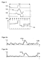
- Fig. 1 shows a schematic sectional view through an optoelectronic sensor according to the invention in an embodiment as a laser scanner 10.
- a light emitter 12 for example with a laser light source, generated by means of a transmitting optical system 14 a transmitted light beam 16.
- the transmitted light beam 16 is emitted by means of a deflection unit 18 in a monitoring area 20 and there from one, if necessary remitted to existing object.
- the remitted light 22 returns to the laser scanner 10 and is detected there via the deflection unit 18 by means of a receiving optical system 24 by a light receiver 26, for example a photodiode or for higher sensitivity of an avalanche photodiode (APD).
- APD avalanche photodiode
- the light emitter 12 and its transmitting optics 14 are located in a central opening of the receiving optics 24.
- the invention also includes alternative solutions, such as with its own mirror range for the transmitted light beam 16 or with divider mirrors.
- the deflection unit 18 is set by a motor 28 in a continuous rotational movement with a scanning frequency. As a result, the transmitted light beam 16 scans one plane during each scanning period, that is to say one complete revolution at the scanning frequency.
- an angle measuring unit 30 is arranged to detect the respective angular position of the deflection unit 18.
- the angle measuring unit 30 is formed here by way of example of a slab as WinkelrichverAvemung and a forked light barrier as a sample.
- An evaluation unit 32 is connected to the light emitter 12, the light receiver 26, the motor 28 and the angle measuring unit 30.
- the light transit time between emission of the transmitted light beam 16 and reception of remitted light 22 is measured to close using the speed of light on the removal of a touched object of the laser scanner 10.
- the respective angular position, below which the transmitted light beam 16 was emitted, is known to the evaluation unit of the angle measuring unit 30.
- the light transit times are negligible compared with the usual rotational frequencies of the deflection unit, so that the transmitted light beam 16 is emitted at practically the same angle as associated remitted light 22 is received.
- the interface 34 also serves as parameterization interface, via which the evaluation unit 32 data can be recorded.
- a separate parameterization interface can be provided.
- the interface 34 can be designed to be safe, in particular a safe output (OSSD, output signal switching device) for a safety-related shutdown signal upon detection of a protective field violation.
- the laser scanner 10 is accommodated in a housing 36, which has a circumferential windshield 38.
- the transit time measurement takes place in a multi-pulse method, which is now based on the Figures 2 and 3 is explained in more detail.
- the multi-pulse method is for the one-dimensional distance switch from the aforementioned DE 10 2007 013 714 and for further explanations reference is made to this.
- the evaluation unit 32 with, for example, two evaluation channels 32a-b here is implemented on a digital module 38, for example an FPGA (Field Programmable Gate Array).
- a digital module 38 for example an FPGA (Field Programmable Gate Array).
- the evaluation unit 32 which also acts as a control unit of the laser scanner 10, via a delay device 40 and a laser driver circuit 42, the light emitter 12 for emitting individual light pulses at well-defined times.
- the delay unit 40 may be implemented by registers, counters and the like of the FPGA.
- the remitted light 22 of a single light pulse is converted by the light receiver 26 into a received pulse and fed to the evaluation unit 22 via an analog preprocessor 44 with a preamplifier 46, a filter 48 and a limiter amplifier 50 and via an A / D converter 52.
- Preamplifier 46 and filter 48 may also be interchanged.
- the resulting signals in the various intermediate stages shows FIG. 3 ,
- the light transmitter 12 generates in each measurement period 100 each a single light pulse, which allows the determination of a precise time.
- a rectangular pulse is suitable for this, but other pulses are also conceivable, such as Gauss pulses.
- the individual light pulse is reflected or remitted in the monitoring area 20 and then converted into an electrical reception pulse 102 in the light receiver 26 and amplified in the transimpedance amplifier 46.
- the reception pulse 102 is idealized Under realistic conditions, noise and distortion would be added.
- the received pulse 102 is always a unipolar signal due to the nature of the light.
- the filter 48 for example a bandpass filter, it becomes a bipolar signal 104, of which only the first two oscillations are shown.
- gray rectangles symbolize a noise level.
- the bipolar signal 104 is amplified into saturation and cut off, so that the actual signal is stretched to a rectangular edge 106 and the noise level represented by gray rectangles in its amplitude over the entire dynamic range.
- the rectangular edge 106 is scanned in the A / D converter 52 designed in particular as a binarizer. Each sample of the sample is symbolized by an arrow 108. The resulting bit string is used in the evaluation unit 32 to form a histogram 110. For each bin an accumulator is provided, which is counted up only if an associated bit value "1". In the case of ideal, no-noise signals, only the bin above which the right flank 106 lies would be filled in this histogram. However, the noise level raised by the limiting amplifier 34 also fills the remaining bins because of the randomness of the noise in the expected value approximately every second measuring period 100.
- the bins are filled by the noise approximately with the value n / 2, with statistical fluctuations being added.
- This value n / 2 corresponds to the signal value zero due to the binarization. From this rises upwards the maximum formed by the positive part of the bipolar signal 104 and downwards the corresponding minimum.
- the intermediate zero crossing detects the evaluation unit 32 in order to determine the reception time independently of the signal level.
- FIG. 3 shows only a relevant section of the measurement period 100 around the reception time. To save memory, this time range can be searched in advance and the histogram 110 can only be formed for part of the measurement period 100.
- each individual light pulse is emitted and collected and evaluated by the evaluation unit 32 per measured value in a histogram 110. Due to the rotational movement of the deflection unit 18, each individual light pulse receives its own angular offset.
- the multi-pulse method supports an exchange relationship between scan frequency, angular resolution and range. These are related to one another via the statistics or averaging depth, that is to say the number of receive pulses 102, which are combined in a histogram 110 for a measured value.
- a fourth conceivable adjusting screw provides the repetition frequency of the individual light pulses, which, however, is assumed to be constant here.
- FIG. 4a shows a temporal intensity curve at low, FIG. 4b however, at higher averaging depth.
- a reception pulse 102b in the near range is well distinguishable from the noise level in both cases.
- a reception pulse 102b in the far range can be made only at the higher averaging depth FIG. 4b separate from the noise. The greater the statistical depth, the higher the range of the laser scanner 10 becomes.
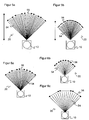
- FIGS. 5 and 6 each show the laser scanner 10 and individual light pulses 54 over a portion of the scanning period in plan view.
- those individual light pulses 54 whose associated receive pulses 102 are each combined in a histogram 110 are connected by an arrow 56.
- a much larger number of, for example, a few hundred or even more individual light pulses 54 would be emitted per degree.
- FIG. 5 explains the interchangeability of angular resolution and range.
- the individual light pulses 54 are each combined to form larger groups 56. Therefore, after the in FIG. 4 illustrated related objects also still in a relatively large range detectable. For this, each group 56 requires a relatively large angular range.
- the groups 56 like in FIG. 5b a finer angular resolution is achieved, the groups 56 become smaller, and the reduced averaging depth leads to a worse signal / noise ratio and thus a reduced range.
- FIG. 6a shows a comparison image at a certain scan frequency. If the scanning frequency is increased, less individual light pulses 54 drop over the same angular range. You can now either as in FIG. 6b shown maintaining the angular resolution. Then the range is reduced due to the lower statistical depth. Alternatively, as in FIG. 6c The range can be maintained, but then worsened the angular resolution, because for the same statistical depth individual light pulses 54 must be collected over a larger angular range. Of course, according to this principle, all intermediate stages are conceivable, in which therefore both range and angular resolution are reduced, but in each case to a lesser extent.
- this interchangeability is utilized and the range, scanning frequency and angular resolution can be configured in a parameterizable manner.
- the user specifies, for example, one or more of the sizes, and the laser scanner 10 adjusts the remaining sizes via the statistical depth.
- adaptive methods are conceivable in which range and angular resolution are variable.
- a temporal dependency is just as possible as a viewing angle dependency. It is then, for example, a certain angular range at low range and high angular resolution, the residual angle range recorded at high range and low angular resolution.
- Another example is a driverless transport vehicle, which first navigates at a coarse angular resolution and long range to then switch to an increasingly better angular resolution upon detection of an object while adjusting the range to the now known object distance. This can also be done angle dependent.
- the multi-pulse method operates quasi-continuously, because the light emitter 12 continuously emits individual light pulses 54, in each case a group 56 of the subsequently registered reception pulses 102 are combined and collected in a histogram 110 and the next group 56 is evaluated directly afterwards. This may create a break for the evaluation itself.
- a gapless scanning system which shows no scan angle at any scan angle.
- the laser scanner is 10 but exposed to more or less large speed fluctuations, for example, by shaking or shaking. Then it may happen that the evaluation for a new measured value would have to start with a new histogram 110 before the current measurement is completed.
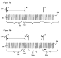
- FIG. 7 illustrates this situation.
- Figure 7a shows an ideal case without speed fluctuation.
- the angle measuring unit 30 supplies uniform, equidistant angular position signals 56, and the individual light pulses 54 or their associated receiving pulses 102 are combined into groups 56 without overlapping.
- the arrows 60 indicate a dead time interval needed for the evaluation of the histogram 110.
- FIG. 7b the time behavior gets mixed up due to a speed fluctuation.
- the group 56a at 4 ° still collects individual light pulses 54, which actually already belong to the group 56b at 5 °.
- a dynamic adjustment of the statistical depth is provided.
- each group is completed when a new angular position signal 58 arrives, regardless of the statistical depth achieved thereby. According to the exchange relationship explained above, this ultimately results in a range fluctuation as a function of the angle, which however is often more acceptable than a scan gap.
- a reserve buffer is then provided in a further embodiment. Between each two groups 56, an enlarged area similar to the dead zone 60 is maintained, in which, ideally Figure 7a no received pulses 102 are added to the histogram 110. If a speed fluctuation then occurs, then the reserve buffer is used to reach the predetermined number of receiving pulses 102 before the next angular position signal 58. Thus, the further the quasi-continuous evaluation, the larger the reserve buffer is selected.
- FIG. 8 shows a further embodiment of the invention, which is used to avoid the reserve buffer and / or to provide in the event that the reserve buffer is insufficient to absorb speed fluctuations.
- FIG. 7 is in the upper part of the FIG. 8 the temporal sequence of the individual light pulses 54 shown.
- the angle signals 58a generated by the angle measuring unit 30 are shown, from which the angular position signals 58 are derived by interpolation with the desired angular resolution.
- the angle measuring unit 30 may directly provide a desired angular grid of angular position signals 58.
- a time period 62 for collecting a predetermined number of receiving pulses 102 including the dead time 60 for the evaluation is less than the time interval between two angular position signals 58. Then, a measured value is generated and the next angular position signal 58 is waited for the next measured value.
- angular position signals 58 which do not trigger a new measurement because the previous measurement still consumes the entire available time budget. This is in the example of FIG. 8 at 5 ° and at 11 ° the case.
- angular position signals 58 initially no measured values are available. However, the measurements can be interpolated as needed by the adjacent angular position signals 58.
- the continuous and seamless monitoring remains ensured because individual light pulses 54 have flowed into the measurement at each intermediate angle. It has continued to take place, based on the real illumination with the transmitted light beam 16, a quasi-continuous scanning. However, the pulse sequence of the individual light pulses 54 with respect to the angle of rotation was applied more slowly than was necessary because of the sudden increase in rotational speed, so that effectively the angular resolution drops temporarily.
- the metrologically most precise evaluation is to provide a plurality of evaluation channels 32a-b. If necessary, one evaluation channel 32a continues its histogram generation also via a further angular position signal 58, while overlapping the other evaluation channel 32b already begins another measurement with the further angular position signal 58 as a start signal.
- the statistical depth and thus the range and the angular resolution then remain completely unaffected by speed fluctuations. Only the independence of the measured values is slightly influenced, because received pulses 102 in the overlap region after the further angular position signal 58 are incorporated twice into the earlier and the later measured value. However, this has no practical effect, because nevertheless all received pulses 102 originate from real measurements at the associated detection angle.
- Multiple evaluation channels 32a-b can additionally or alternatively also be used for subjecting the same measurement data in the form of the reception pulses 102 to a plurality of different evaluations in parallel. This is used for redundant or diversified redundant evaluation of a review of the reliability of the evaluation.
- different criteria can also be applied to the range and angular resolution in the parallel branches. Thus, for example, at the same time a measurement with high range and low angular resolution and a measurement with short range and high angular resolution is performed, and later the required measurement is selected or measurements are compared or offset against each other.
- the parallel evaluation channels 32a-b may also have a mutually different time offset from the angular position signals 58.
- angular scales offset from each other are ultimately scanned similar to a moving average, which are then superimposed on one another for improved angular resolution.
- a moving average there is no need to have memory available for the individual measurements to remove the respective receive pulses 102 from the histogram 110 as the window advances, since a histogram 110 is collected, evaluated, and then discarded.
- these disturbances are taught in calibration measurements with the later angular resolution ex works or at the place of use and then pre-loaded the preload values measured during operation with a negative sign in forming each new histogram in its bins.
- Scaling should be based on the statistics depth used during training and during operation. advantageously, For example, the preload values are already learned with the later statistics depth, but this is not always possible because of the adaptive elements of the invention.
- the learned known disturbance is compensated automatically and at a very early point in time in the measuring path on the basis of the precharging values.
Landscapes
- Engineering & Computer Science (AREA)
- Physics & Mathematics (AREA)
- General Physics & Mathematics (AREA)
- Radar, Positioning & Navigation (AREA)
- Remote Sensing (AREA)
- Computer Networks & Wireless Communication (AREA)
- Electromagnetism (AREA)
- Optical Radar Systems And Details Thereof (AREA)
- Measurement Of Optical Distance (AREA)
Claims (14)
- Capteur optoélectronique (10), en particulier scanneur à laser, pour la détection et la détermination de l'éloignement d'objets dans une zone de surveillance (20), comprenant un émetteur de lumière (12) pour émettre un rayon de lumière émise (16) avec une pluralité d'impulsions lumineuses individuelles successives (54), une unité de déflexion rotative (18) pour la déflexion périodique du rayon de lumière émise (16) vers la zone de surveillance (20), une unité de mesure angulaire (30) pour engendrer des signaux de position angulaire (58) en fonction d'une position angulaire de l'unité de déflexion (18), un récepteur de lumière (26) pour engendrer des impulsions de réception (102) à partir de la lumière émise qui a été réémise ou réfléchie par des objets dans la zone de surveillance (20), et une unité d'évaluation (32) qui est réalisée pour collecter une pluralité d'impulsions de réception (102) dans un histogramme temporel (110) et pour déterminer à partir de l'histogramme (110) le temps de parcours de la lumière depuis le capteur (10) jusqu'à un objet et déterminer à partir de celui-ci une valeur de mesure pour l'éloignement de l'objet,
dans lequel l'unité d'évaluation (32) est réalisée pour sélectionner, respectivement à l'aide du signal de position angulaire (58), un groupe (56) d'impulsions de réception (102) qui sont collectées dans un histogramme (110) et pour associer la valeur de mesure, déterminée à partir de l'histogramme (110) du groupe (56), pour l'éloignement de l'objet à un angle de détection désigné par le signal de position angulaire (58), et la sélection d'impulsions de réception (102) appartenant à un groupe (56) est effectuée de façon retardée dans le temps. - Capteur optoélectronique (10), en particulier scanneur à laser, pour la détection et la détermination d'éloignement d'objets dans une zone de surveillance (20), comprenant un émetteur de lumière (12) pour émettre un rayon de lumière émise (16) avec une pluralité d'impulsions de lumières individuelles successives (54), une unité de déflexion rotative (18) pour la déflexion périodique du rayon de lumière émise (16) vers la zone de surveillance (20), une unité de mesure angulaire (30) pour générer des signaux de position angulaire (58) en fonction d'une position angulaire de l'unité de déflexion (18), un récepteur de lumière (26) pour engendrer des impulsions de réception (102) à partir de la lumière émise réémise ou réfléchie depuis des objets dans la zone de surveillance (20), et une unité d'évaluation (32), qui est réalisée pour collecter une pluralité d'impulsions individuelles (102) dans un histogramme temporel (110) et pour déterminer à partir de l'histogramme (110) le temps de parcours de la lumière depuis le capteur (10) jusqu'à un objet et déterminer à partir de celui-ci une valeur de mesure pour l'éloignement de l'objet,
dans lequel l'unité d'évaluation (32) est réalisé pour sélectionner respectivement à l'aide du signal de position angulaire (58) un groupe (56) d'impulsions de réception (102) qui sont collectées dans un histogramme (110) et pour associer la valeur de mesure, déterminée à partir de l'histogramme (110) du groupe (56), pour l'éloignement de l'objet à un angle de détection désigné par le signal de position angulaire (58), dans lequel le nombre d'impulsions de réception (102) dans un groupe (56) est adapté en fonction de l'angle de détection et/ou en fonction d'un éloignement de l'objet auparavant déterminé. - Capteur (10) selon la revendication 1 ou 2,
dans lequel l'unité de mesure angulaire (30) prépare les signaux de position angulaire avec une résolution angulaire prédéterminée. - Capteur (10) selon l'une des revendications précédentes,
dans lequel le nombre des impulsions individuelles (54) ainsi que l'écart temporel entre deux impulsions lumineuses individuelles (54) sont suffisamment petits pour laisser un tampon temporel entre la dernière impulsion de réception respective d'un groupe (56) et le signal de position angulaire (58) successif. - Capteur (10) selon la revendication 3 ou 4,
dans lequel l'unité d'évaluation (32) est réalisée pour vérifier si, pendant la période dans laquelle le nombre prédéterminé d'impulsions de réception (102) sont détectées, un autre signal de position angulaire (58) se présente et, dans ce cas, pour associer la valeur de mesure, déterminée à partir de l'histogramme (110) du groupe (56), pour l'éloignement de l'objet, au signal de position angulaire (58) auquel appartiennent en majorité les impulsions de réception (102), en particulier à celui pour lequel les écarts temporels additionnés vis-à-vis des impulsions de réception (102) du groupe (56) sont les plus faibles. - Capteur (10) selon l'une des revendications précédentes,
dans lequel l'unité d'évaluation (32) comprend au moins deux canaux d'évaluation (32a-b), afin de collecter dans chacun des canaux d'évaluation des impulsions de réception dans un propre histogramme (110) et pour déterminer respectivement à partir de l'histogramme (110) le temps de parcours de la lumière depuis le capteur (10) jusqu'à un objet et pour déterminer à partir de celui-ci une valeur de mesure pour l'éloignement de l'objet. - Capteur (10) selon la revendication 6,
dans lequel les canaux d'évaluation (32a-b) sont réalisés pour une évaluation à chevauchement dans laquelle de manière respectivement alternée un canal d'évaluation (32a-b) sélectionne un nombre prédéterminé d'impulsions de réception (102) pour un groupe (56), qui suivent un signal de position angulaire. - Capteur (10) selon la revendication 6,
dans lequel les canaux d'évaluation (32a-b) sont réalisés pour une évaluation parallèle, en particulier avec différents critères pour la sélection des impulsions de réception (102) appartenant à un groupe (56). - Capteur (10) selon l'une des revendications précédentes,
dans lequel il est prévu une unité de prétraitement analogique (44) qui comprend un filtre (48) afin de convertir respectivement l'impulsion de réception (102) en un signal bipolaire prétraité (104) et l'admettre via un convertisseur analogique/numérique (52) à l'unité d'évaluation (32), dans lequel en particulier l'unité de prétraitement analogique (44) comprend un amplificateur-limiteur (50) pour amplifier la part positive ou négative du signal (104) jusqu'à une valeur de saturation, et le convertisseur analogique/numérique (52) est un convertisseur binaire. - Capteur (10) selon l'une des revendications précédentes,
qui comprend un dispositif de paramétrage (34) afin d'établir une résolution angulaire plus élevée avec une portée plus faible du capteur (10) ou inversement. - Capteur (10) selon l'une des revendications précédentes,
dans lequel l'histogramme (110) est préchargé avec des valeurs préalables déjà avant la collecte des impulsions de réception (102), dans lequel les valeurs préalables sont en particulier fonction de l'angle de détection. - Capteur (10) selon l'une des revendications précédentes,
dans lequel les valeurs préalables sont déterminées à partir d'une mesure de calibrage dans un état de référence de la zone de surveillance (20), en particulier afin de précharger une réflexion sur un pare-brise avant. - Procédé pour la détection et la détermination d'éloignement d'objets dans une zone de surveillance (20), dans lequel on émet un rayon de lumière émise (16) avec une pluralité d'impulsions de lumière individuelles successives (54), le rayon de lumière émise (16) balaie la zone de surveillance (20) par déflexion périodique et des impulsions de réception (102) sont engendrées à partir de la lumière émise qui est réémise ou réfléchie à partir d'objets dans la zone de surveillance (20), dans lequel l'angle de déflexion est fixé par un signal de position angulaire (58), on collecte une pluralité d'impulsions de réception (102) en un histogramme temporel (110) et on détermine à partir de l'histogramme (110) le temps de parcours de la lumière jusqu'à un objet et on détermine à partir de celui-ci une valeur de mesure pour l'éloignement de l'objet,
dans lequel on sélectionne respectivement à partir du signal de position angulaire (58) un groupe d'impulsions de réception (102) qui sont collectées dans un histogramme (110), on associe la valeur de mesure, déterminée à partir de l'histogramme (110) du groupe, pour l'éloignement d'un objet à un angle de détection désigné par le signal de position angulaire (58), et on effectue la sélection d'impulsions de réception (102) pour former un groupe (56) de manière retardée dans le temps. - Procédé pour la détection et la détermination d'éloignement d'objets dans une zone de surveillance (20), dans lequel on émet un rayon de lumière émise (16) avec une pluralité d'impulsions de lumière individuelles successives (54), le rayon de lumière émise (16) balaye la zone de surveillance (20) par déflexion périodique et des impulsions de réception sont engendrées à partir de la lumière émise qui est réémise ou réfléchie depuis des objets dans la zone de surveillance (20), dans lequel l'angle de déflexion est fixé par un signal de position angulaire (58), on collecte une pluralité d'impulsions de réception (102) dans un histogramme temporel (110) et on détermine à partir de l'histogramme (110) le temps de parcours de la lumière jusqu'à un objet et à partir de celui-ci on détermine une valeur de mesure pour l'éloignement de l'objet,
dans lequel on sélectionne respectivement à l'aide du signal de position angulaire (58) un groupe d'impulsions de réception (102) qui sont collectées dans un histogramme (110), on associe la valeur de mesure, déterminée à partir de l'histogramme (110) du groupe, pour l'éloignement de l'objet, à un angle de détection désigné par le signal de position angulaire (58), et on adapte le nombre d'impulsions de réception (102) dans un groupe (56) en fonction de l'angle de détection et/ou en fonction d'un éloignement préalablement déterminé de l'objet.
Applications Claiming Priority (1)
| Application Number | Priority Date | Filing Date | Title |
|---|---|---|---|
| DE102010061382.7A DE102010061382B4 (de) | 2010-12-21 | 2010-12-21 | Optoelektronischer Sensor und Verfahren zur Erfassung und Abstandsbestimmung von Objekten |
Publications (2)
| Publication Number | Publication Date |
|---|---|
| EP2469296A1 EP2469296A1 (fr) | 2012-06-27 |
| EP2469296B1 true EP2469296B1 (fr) | 2012-10-24 |
Family
ID=44720793
Family Applications (2)
| Application Number | Title | Priority Date | Filing Date |
|---|---|---|---|
| EP11184192A Active EP2469296B1 (fr) | 2010-12-21 | 2011-10-06 | Capteur optoélectronique et procédé destiné à la détection et la détermination de l'éloignement d'objets |
| EP11771194.5A Active EP2635918B1 (fr) | 2010-12-21 | 2011-10-21 | Capteur optoélectronique et procédé de détection d'objets et de détermination de leur distance |
Family Applications After (1)
| Application Number | Title | Priority Date | Filing Date |
|---|---|---|---|
| EP11771194.5A Active EP2635918B1 (fr) | 2010-12-21 | 2011-10-21 | Capteur optoélectronique et procédé de détection d'objets et de détermination de leur distance |
Country Status (6)
| Country | Link |
|---|---|
| US (2) | US9383200B2 (fr) |
| EP (2) | EP2469296B1 (fr) |
| JP (2) | JP2014503820A (fr) |
| DE (1) | DE102010061382B4 (fr) |
| DK (1) | DK2469296T3 (fr) |
| WO (1) | WO2012084298A1 (fr) |
Cited By (19)
| Publication number | Priority date | Publication date | Assignee | Title |
|---|---|---|---|---|
| EP2927711A1 (fr) | 2014-04-04 | 2015-10-07 | Sick Ag | Lecteur laser et procédé de saisie sécurisée d'objets |
| DE102015118258B3 (de) * | 2015-10-27 | 2016-08-04 | Sick Ag | Laserscanner und Verfahren zur Überprüfung von dessen Funktionsfähigkeit |
| EP3208636A1 (fr) | 2016-02-19 | 2017-08-23 | Sick Ag | Capteur optoélectronique et procédé destiné à la saisie d'objets |
| DE102017107667A1 (de) | 2017-04-10 | 2018-10-11 | Sick Ag | Laserscanner und Verfahren zur Überprüfung der Funktionsfähigkeit |
| DE102017117162A1 (de) | 2017-07-28 | 2019-01-31 | Sick Ag | Sensor und Verfahren zur Erfassung und Abstandsbestimmung von Objekten |
| DE102017117694A1 (de) | 2017-08-04 | 2019-02-07 | Sick Ag | Optoelektronischer Sensor und Verfahren zum Erfassen von Objekten in einem Überwachungsbereich |
| EP3470879A1 (fr) | 2017-10-16 | 2019-04-17 | Sick AG | Capteur optoélectronique et procédé de détection sécurisée d'objets |
| US10488550B2 (en) | 2016-06-24 | 2019-11-26 | Sick Ag | Optoelectronic detection of objects by measurement of angular position to determine relative movement of a deflection unit |
| DE102018124837B3 (de) | 2018-10-09 | 2019-12-24 | Sick Ag | Sicherheitslaserscanner und Verfahren zum Erhalt der Funktionsfähigkeit |
| DE202019100793U1 (de) | 2019-02-12 | 2020-05-15 | Sick Ag | Optoelektronischer Sensor zur Erfassung von Objekten |
| DE102019111852B3 (de) | 2019-05-07 | 2020-06-04 | Sick Ag | Sicherheitslaserscanner und Verfahren |
| EP3671264A1 (fr) | 2018-12-21 | 2020-06-24 | Sick Ag | Capteur et procédé de détection d'un objet |
| DE102017103791B4 (de) | 2017-02-23 | 2021-09-30 | Sick Ag | Optoelektronischer Sensor und Verfahren zur Erfassung von Objekten |
| EP3951427A1 (fr) | 2020-08-07 | 2022-02-09 | Sick Ag | Capteur optoélectronique et procédé de surveillance de par-brise |
| DE102020120908A1 (de) | 2020-08-07 | 2022-02-10 | Sick Ag | Optoelektronischer Sensor und Verfahren zur Frontscheibenüberwachung |
| EP4060374A1 (fr) | 2021-03-15 | 2022-09-21 | Sick Ag | Détection d'un objet dans une zone de surveillance |
| EP4086661A1 (fr) | 2021-05-04 | 2022-11-09 | Sick Ag | Capteur optoélectronique et procédé de surveillance d'une vitre avant |
| EP4109127A1 (fr) | 2021-06-21 | 2022-12-28 | Sick Ag | Capteur optoélectronique et procédé de détection des objets |
| EP4254001A1 (fr) | 2022-04-01 | 2023-10-04 | Sick Ag | Détection d'objets dans une zone de surveillance |
Families Citing this family (118)
| Publication number | Priority date | Publication date | Assignee | Title |
|---|---|---|---|---|
| DE102009010465B3 (de) | 2009-02-13 | 2010-05-27 | Faro Technologies, Inc., Lake Mary | Laserscanner |
| US9551575B2 (en) | 2009-03-25 | 2017-01-24 | Faro Technologies, Inc. | Laser scanner having a multi-color light source and real-time color receiver |
| DE102009015920B4 (de) | 2009-03-25 | 2014-11-20 | Faro Technologies, Inc. | Vorrichtung zum optischen Abtasten und Vermessen einer Umgebung |
| US9113023B2 (en) | 2009-11-20 | 2015-08-18 | Faro Technologies, Inc. | Three-dimensional scanner with spectroscopic energy detector |
| DE102009055988B3 (de) | 2009-11-20 | 2011-03-17 | Faro Technologies, Inc., Lake Mary | Vorrichtung zum optischen Abtasten und Vermessen einer Umgebung |
| US9210288B2 (en) | 2009-11-20 | 2015-12-08 | Faro Technologies, Inc. | Three-dimensional scanner with dichroic beam splitters to capture a variety of signals |
| DE102009055989B4 (de) | 2009-11-20 | 2017-02-16 | Faro Technologies, Inc. | Vorrichtung zum optischen Abtasten und Vermessen einer Umgebung |
| US9529083B2 (en) | 2009-11-20 | 2016-12-27 | Faro Technologies, Inc. | Three-dimensional scanner with enhanced spectroscopic energy detector |
| DE102009057101A1 (de) | 2009-11-20 | 2011-05-26 | Faro Technologies, Inc., Lake Mary | Vorrichtung zum optischen Abtasten und Vermessen einer Umgebung |
| US9607239B2 (en) | 2010-01-20 | 2017-03-28 | Faro Technologies, Inc. | Articulated arm coordinate measurement machine having a 2D camera and method of obtaining 3D representations |
| US9879976B2 (en) | 2010-01-20 | 2018-01-30 | Faro Technologies, Inc. | Articulated arm coordinate measurement machine that uses a 2D camera to determine 3D coordinates of smoothly continuous edge features |
| CN102713498B (zh) | 2010-01-20 | 2014-07-16 | 法罗技术股份有限公司 | 用于坐标测量机的安装装置 |
| US9163922B2 (en) | 2010-01-20 | 2015-10-20 | Faro Technologies, Inc. | Coordinate measurement machine with distance meter and camera to determine dimensions within camera images |
| US9628775B2 (en) | 2010-01-20 | 2017-04-18 | Faro Technologies, Inc. | Articulated arm coordinate measurement machine having a 2D camera and method of obtaining 3D representations |
| DE102010020925B4 (de) | 2010-05-10 | 2014-02-27 | Faro Technologies, Inc. | Verfahren zum optischen Abtasten und Vermessen einer Umgebung |
| DE102010032726B3 (de) | 2010-07-26 | 2011-11-24 | Faro Technologies, Inc. | Vorrichtung zum optischen Abtasten und Vermessen einer Umgebung |
| DE102010032725B4 (de) | 2010-07-26 | 2012-04-26 | Faro Technologies, Inc. | Vorrichtung zum optischen Abtasten und Vermessen einer Umgebung |
| DE102010032723B3 (de) | 2010-07-26 | 2011-11-24 | Faro Technologies, Inc. | Vorrichtung zum optischen Abtasten und Vermessen einer Umgebung |
| DE102010033561B3 (de) | 2010-07-29 | 2011-12-15 | Faro Technologies, Inc. | Vorrichtung zum optischen Abtasten und Vermessen einer Umgebung |
| US9168654B2 (en) | 2010-11-16 | 2015-10-27 | Faro Technologies, Inc. | Coordinate measuring machines with dual layer arm |
| DE102012100609A1 (de) | 2012-01-25 | 2013-07-25 | Faro Technologies, Inc. | Vorrichtung zum optischen Abtasten und Vermessen einer Umgebung |
| KR20130102400A (ko) * | 2012-03-07 | 2013-09-17 | 삼성전자주식회사 | 티오에프 센서 및 티오에프 카메라 |
| DE102012101909B3 (de) * | 2012-03-07 | 2013-01-03 | Sick Ag | Entfernungsmessender Sensor und Verfahren zur Synchronisierung |
| US8997362B2 (en) | 2012-07-17 | 2015-04-07 | Faro Technologies, Inc. | Portable articulated arm coordinate measuring machine with optical communications bus |
| DE102012107544B3 (de) * | 2012-08-17 | 2013-05-23 | Faro Technologies, Inc. | Vorrichtung zum optischen Abtasten und Vermessen einer Umgebung |
| DE102012109481A1 (de) | 2012-10-05 | 2014-04-10 | Faro Technologies, Inc. | Vorrichtung zum optischen Abtasten und Vermessen einer Umgebung |
| US9513107B2 (en) | 2012-10-05 | 2016-12-06 | Faro Technologies, Inc. | Registration calculation between three-dimensional (3D) scans based on two-dimensional (2D) scan data from a 3D scanner |
| US10067231B2 (en) | 2012-10-05 | 2018-09-04 | Faro Technologies, Inc. | Registration calculation of three-dimensional scanner data performed between scans based on measurements by two-dimensional scanner |
| AT513402B1 (de) * | 2012-10-05 | 2014-09-15 | Riegl Laser Measurement Sys | Verfahren zur Entfernungsmessung |
| EP2735887B1 (fr) | 2012-11-22 | 2015-06-03 | Sick Ag | Dispositif d'enregistrement optique |
| DE102012112615B3 (de) * | 2012-12-19 | 2014-06-26 | Sick Ag | Optoelektronischer Sensor und Verfahren zur Veränderung der Messrichtung eines optoelektronischen Sensors |
| DE202012105043U1 (de) | 2012-12-21 | 2014-03-31 | Sick Ag | Entfernungsmessender optoelektronischer Sensor zur Erfassung und Abstandsbestimmung von Objekten |
| DE202013100327U1 (de) | 2013-01-24 | 2014-04-29 | Sick Ag | Optoelektronischer Sensor zur Erfassung von Objekten in einem Überwachungsbereich |
| US9276031B2 (en) | 2013-03-04 | 2016-03-01 | Apple Inc. | Photodiode with different electric potential regions for image sensors |
| US9741754B2 (en) | 2013-03-06 | 2017-08-22 | Apple Inc. | Charge transfer circuit with storage nodes in image sensors |
| EP2824478B1 (fr) | 2013-07-11 | 2015-05-06 | Sick Ag | Capteur optoélectronique et procédé destiné à la détection d'objets et à la détermination de distance dans une zone de surveillance |
| DE102013219567A1 (de) * | 2013-09-27 | 2015-04-02 | Robert Bosch Gmbh | Verfahren zur Steuerung eines Mikrospiegelscanners und Mikrospiegelscanner |
| DE102014100696B3 (de) | 2014-01-22 | 2014-12-31 | Sick Ag | Entfernungsmessender Sensor und Verfahren zur Erfassung und Abstandsbestimmung von Objekten |
| US10285626B1 (en) | 2014-02-14 | 2019-05-14 | Apple Inc. | Activity identification using an optical heart rate monitor |
| JP6171975B2 (ja) * | 2014-02-21 | 2017-08-02 | 株式会社豊田中央研究所 | ヒストグラム作成装置及びレーザレーダ装置 |
| DE102014106465C5 (de) | 2014-05-08 | 2018-06-28 | Sick Ag | Entfernungsmessender Sensor und Verfahren zur Erfassung und Abstandsbestimmung von Objekten |
| DE102014106463A1 (de) | 2014-05-08 | 2015-11-12 | Sick Ag | Entfernungsmessender Sensor und Verfahren zur Erfassung und Abstandsbestimmung von Objekten |
| US9686485B2 (en) | 2014-05-30 | 2017-06-20 | Apple Inc. | Pixel binning in an image sensor |
| JP2017537309A (ja) | 2014-10-07 | 2017-12-14 | エックスワイゼッド・インタラクティヴ・テクノロジーズ・インコーポレーテッド | 向き付けおよび位置付けのための装置および方法 |
| DE102014115260B3 (de) * | 2014-10-20 | 2015-11-12 | Sick Ag | Sicherheitssystem zur Absicherung der Umgebung eines Objekts |
| EP3059608B1 (fr) | 2015-02-20 | 2016-11-30 | Sick Ag | Capteur optoélectronique et procédé destiné à la détection d'objets |
| JP6498513B2 (ja) * | 2015-04-30 | 2019-04-10 | 株式会社トプコン | 3次元測量装置及び3次元測量方法 |
| US10613225B2 (en) | 2015-09-21 | 2020-04-07 | Kabushiki Kaisha Toshiba | Distance measuring device |
| DE102015122844A1 (de) | 2015-12-27 | 2017-06-29 | Faro Technologies, Inc. | 3D-Messvorrichtung mit Batteriepack |
| EP3397986A4 (fr) * | 2015-12-28 | 2019-08-07 | Leddartech Inc. | Caractérisation et élimination de bruit statique intrinsèque |
| DE102016106417B3 (de) * | 2016-04-08 | 2017-05-11 | Sick Ag | Optoelektronischer Sensor mit einem Messdatenspeicher und Speichertestverfahren |
| EP3232224B1 (fr) | 2016-04-12 | 2018-06-13 | Sick Ag | Capteur telemetrique optoelectronique et procede de detection et de determination de distances entre des objets |
| US10048120B2 (en) | 2016-05-03 | 2018-08-14 | Datalogic IP Tech, S.r.l. | Laser scanner and optical system |
| US9964437B2 (en) | 2016-05-03 | 2018-05-08 | Datalogic IP Tech, S.r.l. | Laser scanner with reduced internal optical reflection comprising a light detector disposed between an interference filter and a collecting mirror |
| US11585905B2 (en) | 2016-05-03 | 2023-02-21 | Datalogic Ip Tech S.R.L. | Laser scanner |
| JP6741475B2 (ja) * | 2016-05-20 | 2020-08-19 | 株式会社日立国際電気 | 監視システム及び監視方法 |
| KR101840116B1 (ko) * | 2016-06-28 | 2018-03-19 | 인하대학교 산학협력단 | 고속 감지 회전형 라이더 센서 시스템 |
| US10061021B2 (en) | 2016-07-06 | 2018-08-28 | Datalogic IP Tech, S.r.l. | Clutter filter configuration for safety laser scanner |
| WO2018009981A1 (fr) | 2016-07-15 | 2018-01-18 | Fastbrick Ip Pty Ltd | Machine de pose de briques/blocs incorporée dans un véhicule |
| US10865578B2 (en) | 2016-07-15 | 2020-12-15 | Fastbrick Ip Pty Ltd | Boom for material transport |
| US10658419B2 (en) | 2016-09-23 | 2020-05-19 | Apple Inc. | Stacked backside illuminated SPAD array |
| DE102016118758A1 (de) * | 2016-10-04 | 2018-04-05 | Sick Ag | Optoelektronischer Sensor und Verfahren zur optischen Erfassung eines Überwachungsbereichs |
| US20180120439A1 (en) * | 2016-11-03 | 2018-05-03 | Honeywell International Inc. | Systems and methods for using dissimilar lidar technologies |
| EP3330741B1 (fr) | 2016-12-05 | 2019-02-13 | Sick Ag | Capteur optoélectronique et procédé de détection d'objets dans une zone de détection |
| US10942272B2 (en) * | 2016-12-13 | 2021-03-09 | Waymo Llc | Power modulation for a rotary light detection and ranging (LIDAR) device |
| IT201600132849A1 (it) | 2016-12-30 | 2018-06-30 | Datalogic IP Tech Srl | Sistema di sicurezza includente una pluralità di laser scanner e metodo di gestione di una pluralità di laser scanner |
| KR101923724B1 (ko) | 2017-01-02 | 2019-02-22 | 전자부품연구원 | 송수광 일체형 광학계 모듈 및 이를 구비하는 스캐닝 라이다 |
| CN110235024B (zh) | 2017-01-25 | 2022-10-28 | 苹果公司 | 具有调制灵敏度的spad检测器 |
| US10656251B1 (en) | 2017-01-25 | 2020-05-19 | Apple Inc. | Signal acquisition in a SPAD detector |
| US10962628B1 (en) | 2017-01-26 | 2021-03-30 | Apple Inc. | Spatial temporal weighting in a SPAD detector |
| US11105925B2 (en) | 2017-03-01 | 2021-08-31 | Ouster, Inc. | Accurate photo detector measurements for LIDAR |
| JP7134988B2 (ja) * | 2017-03-01 | 2022-09-12 | アウスター インコーポレイテッド | ライダーのための正確な光検出器測定 |
| DE102017204587A1 (de) * | 2017-03-20 | 2018-09-20 | Robert Bosch Gmbh | Verfahren und Vorrichtung zum Abtasten eines Raumwinkels |
| EP3388863A1 (fr) * | 2017-04-10 | 2018-10-17 | Bea S.A. | Capteur pour commander une porte automatique |
| DE102017207317B4 (de) * | 2017-05-02 | 2022-03-03 | Fraunhofer-Gesellschaft zur Förderung der angewandten Forschung e.V. | Vorrichtung zur Ermittlung eines Abstands zu einem Objekt sowie entsprechendes Verfahren |
| DE102017113674B4 (de) * | 2017-06-21 | 2019-03-28 | Sick Ag | Optoelektronischer Sensor und Verfahren zur Messung der Entfernung zu einem Objekt |
| WO2019006511A1 (fr) | 2017-07-05 | 2019-01-10 | Fastbrick Ip Pty Ltd | Dispositif de suivi de position et d'orientation en temps réel |
| US10622538B2 (en) | 2017-07-18 | 2020-04-14 | Apple Inc. | Techniques for providing a haptic output and sensing a haptic input using a piezoelectric body |
| KR101938984B1 (ko) * | 2017-08-09 | 2019-04-10 | 연세대학교 산학협력단 | Spad 거리측정 센서 기반의 2단계 트래킹을 이용한 거리 측정 장치 및 방법 |
| CN111226090B (zh) | 2017-08-17 | 2023-05-23 | 快砖知识产权私人有限公司 | 具有改进的横滚角测量的激光跟踪器 |
| EP3669242A4 (fr) | 2017-08-17 | 2021-07-21 | Fastbrick IP Pty Ltd | Système de communication pour un système d'interaction |
| FR3070498B1 (fr) * | 2017-08-28 | 2020-08-14 | Stmicroelectronics Rousset | Dispositif et procede de determination de la presence ou de l'absence et eventuellement du deplacement d'un objet contenu dans un logement |
| US10440301B2 (en) | 2017-09-08 | 2019-10-08 | Apple Inc. | Image capture device, pixel, and method providing improved phase detection auto-focus performance |
| EP3460509A1 (fr) * | 2017-09-22 | 2019-03-27 | ams AG | Procédé d'étalonnage d'un système de temps de vol et système de temps de vol |
| US11401115B2 (en) | 2017-10-11 | 2022-08-02 | Fastbrick Ip Pty Ltd | Machine for conveying objects and multi-bay carousel for use therewith |
| JP7069629B2 (ja) * | 2017-10-13 | 2022-05-18 | 株式会社リコー | 距離測定装置、移動体、距離測定方法およびプログラム |
| US11105898B2 (en) * | 2017-12-29 | 2021-08-31 | Symbol Technologies, Llc | Adaptive illumination system for 3D-time of flight sensor |
| JP7040042B2 (ja) * | 2018-01-24 | 2022-03-23 | 株式会社リコー | 時間測定装置、距離測定装置、移動体装置、時間測定方法及び距離測定方法 |
| US11079723B2 (en) | 2018-02-06 | 2021-08-03 | Integrated Device Technology, Inc. | Apparatus and methods for automatic time measurements |
| EP3525004B1 (fr) * | 2018-02-08 | 2020-10-14 | Cedes AG | Capteur tof pourvu d'émetteur de contrôle |
| DE102018203533A1 (de) * | 2018-03-08 | 2019-09-12 | Ibeo Automotive Systems GmbH | Empfangsanordnung zum Empfang von Lichtsignalen und Verfahren zum Empfangen von Lichtsignalen |
| DE102018203534A1 (de) * | 2018-03-08 | 2019-09-12 | Ibeo Automotive Systems GmbH | Empfängeranordnung zum Empfang von Lichtimpulsen, LiDAR-Modul und Verfahren zum Empfangen von Lichtimpulsen |
| US10497738B2 (en) * | 2018-04-20 | 2019-12-03 | Omnivision Technologies, Inc. | First photon correlated time-of-flight sensor |
| US11029397B2 (en) * | 2018-04-20 | 2021-06-08 | Omnivision Technologies, Inc. | Correlated time-of-flight sensor |
| JP7214363B2 (ja) * | 2018-04-27 | 2023-01-30 | ソニーセミコンダクタソリューションズ株式会社 | 測距処理装置、測距モジュール、測距処理方法、およびプログラム |
| EP3572971B1 (fr) * | 2018-05-22 | 2021-02-24 | Sick Ag | Protection d'une zone de surveillance à au moins une machine |
| DE102018113848A1 (de) | 2018-06-11 | 2019-12-12 | Sick Ag | Optoelektronischer Sensor und Verfahren zur Erfassung von dreidimensionalen Bilddaten |
| CN109061216B (zh) * | 2018-07-03 | 2020-01-24 | 河南森源重工有限公司 | 一种转速传感器及电机 |
| US10848693B2 (en) | 2018-07-18 | 2020-11-24 | Apple Inc. | Image flare detection using asymmetric pixels |
| US11019294B2 (en) | 2018-07-18 | 2021-05-25 | Apple Inc. | Seamless readout mode transitions in image sensors |
| DE102018117826A1 (de) * | 2018-07-24 | 2020-01-30 | Valeo Schalter Und Sensoren Gmbh | Verfahren zum Betreiben eines optoelektronischen Sensors zur Erfassung eines Objekts und optoelektronischer Sensor |
| US11536845B2 (en) * | 2018-10-31 | 2022-12-27 | Waymo Llc | LIDAR systems with multi-faceted mirrors |
| US11233966B1 (en) | 2018-11-29 | 2022-01-25 | Apple Inc. | Breakdown voltage monitoring for avalanche diodes |
| JP7339277B2 (ja) * | 2018-11-30 | 2023-09-05 | 株式会社小糸製作所 | 測距センサおよび車両用灯具、測距方法 |
| EP3663798B1 (fr) | 2018-12-07 | 2021-01-27 | Sick Ag | Détecteur optoélectronique et procédé de détection et de détermination de distance des objets |
| DE102019106411B4 (de) * | 2019-03-13 | 2021-06-10 | Jenoptik Optical Systems Gmbh | Laserscaneinrichtung und Verfahren zur dreidimensionalen Vermessung einer Szenerie in großer Entfernung |
| EP3712647B1 (fr) | 2019-03-18 | 2021-04-28 | Sick Ag | Capteur optoélectronique et procédé de détection d'objets |
| DE102019107681B4 (de) * | 2019-03-26 | 2022-12-01 | Sick Ag | Verfahren zum Betreiben eines abstandsmessenden Überwachungssensors und abstandsmessender Überwachungssensor |
| DE102019125684B4 (de) | 2019-09-24 | 2022-07-28 | Sick Ag | Optoelektronischer Sensor und Verfahren zur Erfassung von Objekten |
| US11668832B2 (en) | 2020-01-31 | 2023-06-06 | Denso Corporation | LIDAR device and method for calculating distance to object |
| CN115151139A (zh) | 2020-02-27 | 2022-10-04 | 大塚食品株式会社 | 含植物性蛋白食品 |
| US11476372B1 (en) | 2020-05-13 | 2022-10-18 | Apple Inc. | SPAD-based photon detectors with multi-phase sampling TDCs |
| FR3115888B1 (fr) | 2020-10-30 | 2023-04-14 | St Microelectronics Grenoble 2 | Procédé de détection d’une présence d’un objet dans un champ de vision d’un capteur temps de vol |
| DE202021102461U1 (de) | 2021-05-06 | 2022-08-11 | Leuze Electronic Gmbh + Co. Kg | Optischer Sensor |
| CN113759342B (zh) * | 2021-08-31 | 2023-10-24 | 柳州柳工叉车有限公司 | 一种激光雷达的扫描方法、装置、计算机设备和存储介质 |
| KR102645857B1 (ko) | 2021-11-11 | 2024-03-11 | 주식회사 오토닉스 | 레이저 스캐너 |
| DE202022103929U1 (de) * | 2022-07-13 | 2023-10-16 | Leuze Electronic Gmbh + Co. Kg | Optischer Sensor |
| WO2024034639A1 (fr) * | 2022-08-10 | 2024-02-15 | パナソニックIpマネジメント株式会社 | Appareil et procédé d'inspection de région, ainsi que programme |
Family Cites Families (22)
| Publication number | Priority date | Publication date | Assignee | Title |
|---|---|---|---|---|
| DE4340756C5 (de) | 1992-12-08 | 2006-08-10 | Sick Ag | Laserabstandsermittlungsvorrichtung |
| JPH06186335A (ja) * | 1992-12-18 | 1994-07-08 | Omron Corp | 距離計測装置 |
| DE10025258A1 (de) * | 2000-05-22 | 2001-12-06 | Adc Automotive Dist Control | Optisches System |
| JP3953908B2 (ja) * | 2002-07-25 | 2007-08-08 | 株式会社京三製作所 | 交通信号制御装置 |
| JP2004067035A (ja) * | 2002-08-09 | 2004-03-04 | East Japan Railway Co | 踏切障害物検知装置 |
| JP2004177350A (ja) * | 2002-11-28 | 2004-06-24 | Denso Corp | 車両用レーダ装置 |
| JP2004309230A (ja) * | 2003-04-03 | 2004-11-04 | Mitsubishi Electric Corp | 測距装置 |
| EP1522870B1 (fr) | 2003-10-06 | 2013-07-17 | Triple-IN Holding AG | Mesure de distance |
| US6970662B2 (en) * | 2003-12-22 | 2005-11-29 | Xerox Corporation | Systems and methods for in situ setting charge voltages in a dual recharge system |
| JP4069926B2 (ja) * | 2005-01-11 | 2008-04-02 | 株式会社Ihi | 物体検出装置 |
| US7260487B2 (en) * | 2005-11-29 | 2007-08-21 | International Business Machines Corporation | Histogram difference method and system for power/performance measurement and management |
| JP2007316016A (ja) * | 2006-05-29 | 2007-12-06 | Mitsubishi Electric Corp | レーダ装置 |
| DE102006048166A1 (de) * | 2006-08-02 | 2008-02-07 | Daimler Ag | Verfahren zur Beobachtung einer Person in einem industriellen Umfeld |
| JP2008096181A (ja) * | 2006-10-10 | 2008-04-24 | Nikon Vision Co Ltd | 距離測定装置 |
| DE102007013714A1 (de) | 2007-03-22 | 2008-10-02 | Sick Ag | Optoelektronischer Sensor und Verfahren zur Messung einer Entfernung oder einer Entfernungsänderung |
| JP5388045B2 (ja) * | 2007-07-24 | 2014-01-15 | 北陽電機株式会社 | 搬送台車及び光測距装置 |
| US8315473B1 (en) * | 2008-08-22 | 2012-11-20 | Adobe Systems Incorporated | Variably fast and continuous bilateral approximation filtering using histogram manipulations |
| EP2189814B1 (fr) | 2008-11-21 | 2010-07-21 | Sick Ag | Capteur optoélectronique et procédé destiné à la mesure d'éloignements selon le principe du temps de propagation de la lumière |
| ATE483993T1 (de) * | 2008-11-21 | 2010-10-15 | Sick Ag | Optoelektronischer sensor und verfahren zur messung von entfernungen nach dem lichtlaufzeitprinzip |
| ES2354113T3 (es) | 2008-11-21 | 2011-03-10 | Sick Ag | Sensor optoelectrónico y procedimiento para medir distancias según el principio del tiempo de propagacion de la luz. |
| JP5398306B2 (ja) * | 2009-03-04 | 2014-01-29 | 古野電気株式会社 | レーダ装置 |
| EP2315045B1 (fr) * | 2009-10-22 | 2012-08-01 | Sick Ag | Mesure des éloignements ou des modifications d'éloignement |
-
2010
- 2010-12-21 DE DE102010061382.7A patent/DE102010061382B4/de active Active
-
2011
- 2011-10-06 EP EP11184192A patent/EP2469296B1/fr active Active
- 2011-10-06 DK DK11184192.0T patent/DK2469296T3/da active
- 2011-10-21 WO PCT/EP2011/068446 patent/WO2012084298A1/fr active Application Filing
- 2011-10-21 US US13/996,238 patent/US9383200B2/en active Active
- 2011-10-21 JP JP2013545123A patent/JP2014503820A/ja active Pending
- 2011-10-21 EP EP11771194.5A patent/EP2635918B1/fr active Active
- 2011-12-19 US US13/330,169 patent/US8724096B2/en active Active
- 2011-12-20 JP JP2011278693A patent/JP5596011B2/ja active Active
Cited By (25)
| Publication number | Priority date | Publication date | Assignee | Title |
|---|---|---|---|---|
| EP2927711A1 (fr) | 2014-04-04 | 2015-10-07 | Sick Ag | Lecteur laser et procédé de saisie sécurisée d'objets |
| US9423499B2 (en) | 2014-04-04 | 2016-08-23 | Sick Ag | Laser scanner and method for a safe detection of objects |
| DE102015118258B3 (de) * | 2015-10-27 | 2016-08-04 | Sick Ag | Laserscanner und Verfahren zur Überprüfung von dessen Funktionsfähigkeit |
| EP3163322A1 (fr) | 2015-10-27 | 2017-05-03 | Sick Ag | Scanner laser et procédé de vérification de sa capacité de fonctionnement |
| EP3208636A1 (fr) | 2016-02-19 | 2017-08-23 | Sick Ag | Capteur optoélectronique et procédé destiné à la saisie d'objets |
| US10488550B2 (en) | 2016-06-24 | 2019-11-26 | Sick Ag | Optoelectronic detection of objects by measurement of angular position to determine relative movement of a deflection unit |
| DE102017103791B4 (de) | 2017-02-23 | 2021-09-30 | Sick Ag | Optoelektronischer Sensor und Verfahren zur Erfassung von Objekten |
| DE102017107667A1 (de) | 2017-04-10 | 2018-10-11 | Sick Ag | Laserscanner und Verfahren zur Überprüfung der Funktionsfähigkeit |
| DE102017117162A1 (de) | 2017-07-28 | 2019-01-31 | Sick Ag | Sensor und Verfahren zur Erfassung und Abstandsbestimmung von Objekten |
| DE102017117694A1 (de) | 2017-08-04 | 2019-02-07 | Sick Ag | Optoelektronischer Sensor und Verfahren zum Erfassen von Objekten in einem Überwachungsbereich |
| EP3470879A1 (fr) | 2017-10-16 | 2019-04-17 | Sick AG | Capteur optoélectronique et procédé de détection sécurisée d'objets |
| DE102018124837B3 (de) | 2018-10-09 | 2019-12-24 | Sick Ag | Sicherheitslaserscanner und Verfahren zum Erhalt der Funktionsfähigkeit |
| US11624823B2 (en) | 2018-10-09 | 2023-04-11 | Sick Ag | Safety laser scanner and method for maintaining operability |
| US11592552B2 (en) | 2018-12-21 | 2023-02-28 | Sick Ag | Sensor and method for detecting an object |
| EP3671264A1 (fr) | 2018-12-21 | 2020-06-24 | Sick Ag | Capteur et procédé de détection d'un objet |
| DE102018133281A1 (de) | 2018-12-21 | 2020-06-25 | Sick Ag | Sensor und Verfahren zur Erfassung eines Objekts |
| DE202019100793U1 (de) | 2019-02-12 | 2020-05-15 | Sick Ag | Optoelektronischer Sensor zur Erfassung von Objekten |
| DE102019111852B3 (de) | 2019-05-07 | 2020-06-04 | Sick Ag | Sicherheitslaserscanner und Verfahren |
| EP3736605A2 (fr) | 2019-05-07 | 2020-11-11 | Sick Ag | Balayeur laser de sécurité et procédé |
| DE102020120908A1 (de) | 2020-08-07 | 2022-02-10 | Sick Ag | Optoelektronischer Sensor und Verfahren zur Frontscheibenüberwachung |
| EP3951427A1 (fr) | 2020-08-07 | 2022-02-09 | Sick Ag | Capteur optoélectronique et procédé de surveillance de par-brise |
| EP4060374A1 (fr) | 2021-03-15 | 2022-09-21 | Sick Ag | Détection d'un objet dans une zone de surveillance |
| EP4086661A1 (fr) | 2021-05-04 | 2022-11-09 | Sick Ag | Capteur optoélectronique et procédé de surveillance d'une vitre avant |
| EP4109127A1 (fr) | 2021-06-21 | 2022-12-28 | Sick Ag | Capteur optoélectronique et procédé de détection des objets |
| EP4254001A1 (fr) | 2022-04-01 | 2023-10-04 | Sick Ag | Détection d'objets dans une zone de surveillance |
Also Published As
| Publication number | Publication date |
|---|---|
| US20120154786A1 (en) | 2012-06-21 |
| EP2469296A1 (fr) | 2012-06-27 |
| US20130301030A1 (en) | 2013-11-14 |
| JP2012132917A (ja) | 2012-07-12 |
| EP2635918B1 (fr) | 2015-03-11 |
| DE102010061382B4 (de) | 2019-02-14 |
| US8724096B2 (en) | 2014-05-13 |
| JP2014503820A (ja) | 2014-02-13 |
| EP2635918A1 (fr) | 2013-09-11 |
| DE102010061382A1 (de) | 2012-06-21 |
| US9383200B2 (en) | 2016-07-05 |
| DK2469296T3 (da) | 2012-12-10 |
| JP5596011B2 (ja) | 2014-09-24 |
| WO2012084298A1 (fr) | 2012-06-28 |
Similar Documents
| Publication | Publication Date | Title |
|---|---|---|
| EP2469296B1 (fr) | Capteur optoélectronique et procédé destiné à la détection et la détermination de l'éloignement d'objets | |
| EP2824478B1 (fr) | Capteur optoélectronique et procédé destiné à la détection d'objets et à la détermination de distance dans une zone de surveillance | |
| EP2541273B1 (fr) | Détection et détermination de distance d'objets | |
| EP2899565B1 (fr) | Capteur mesurant l'éloignement et procédé destiné à la détection et la détermination de l'éloignement d'objets | |
| EP2626722B1 (fr) | Capteur optoélectronique et procédé destiné à la détection et la détermination de l'éloignement d'objets | |
| EP3232224B1 (fr) | Capteur telemetrique optoelectronique et procede de detection et de determination de distances entre des objets | |
| DE102014106465C5 (de) | Entfernungsmessender Sensor und Verfahren zur Erfassung und Abstandsbestimmung von Objekten | |
| EP1972961B1 (fr) | Capteur optoélectronique et procédé de mesure de l'éloignement ou de la modification de l'éloignement | |
| EP3557286B1 (fr) | Capteur optoélectronique et procédé de détection et de détermination de distance d'un objet | |
| EP2942644B1 (fr) | Capteur télémétrique et procédé destiné à la détection et la détermination de l'éloignement d'objets | |
| EP2395368A1 (fr) | Scanner laser mesurant l'éloignement destiné à la détection d'objets dans une zone de surveillance | |
| EP3220164B1 (fr) | Procédé de fonctionnement d'un capteur écartométrique de surveillance et capteur écartométrique de surveillance | |
| EP3770633B1 (fr) | Capteur optoélectronique et procédé de détermination de distance | |
| DE102012101909B3 (de) | Entfernungsmessender Sensor und Verfahren zur Synchronisierung | |
| WO2018172258A1 (fr) | Système lidar à base de spad (photodiodes avalanche à photon unique) | |
| DE102010064682B3 (de) | Optoelektronischer Sensor und Verfahren zur Erfassung und Abstandsbestimmung von Objekten | |
| DE102014110203B3 (de) | Entfernungsmessender Sensor zur Erfassung und Abstandsbestimmung von Objekten | |
| EP3839556B1 (fr) | Capteur optoélectronique et procédé de détection d'un objet | |
| DE202014103348U1 (de) | Entfernungsmessender Sensor zur Erfassung und Abstandsbestimmung von Objekten | |
| DE202019100793U1 (de) | Optoelektronischer Sensor zur Erfassung von Objekten | |
| EP3663798B1 (fr) | Détecteur optoélectronique et procédé de détection et de détermination de distance des objets | |
| DE102007036632B4 (de) | Optischer Sensor und Verfahren zum Nachweis von Objekten in einem Überwachungsbereich | |
| EP2910972A1 (fr) | Capteur mesurant l'éloignement et procédé destiné à la détermination de distance d'objets dans une zone de surveillance | |
| WO2020182255A1 (fr) | Dispositif de balayage laser et procédé de mesure tridimensionnelle d'une scène à une distance élevée | |
| DE202012100807U1 (de) | Entfernungsmessender Sensor |
Legal Events
| Date | Code | Title | Description |
|---|---|---|---|
| 17P | Request for examination filed |
Effective date: 20120418 |
|
| AK | Designated contracting states |
Kind code of ref document: A1 Designated state(s): AL AT BE BG CH CY CZ DE DK EE ES FI FR GB GR HR HU IE IS IT LI LT LU LV MC MK MT NL NO PL PT RO RS SE SI SK SM TR |
|
| AX | Request for extension of the european patent |
Extension state: BA ME |
|
| PUAI | Public reference made under article 153(3) epc to a published international application that has entered the european phase |
Free format text: ORIGINAL CODE: 0009012 |
|
| GRAP | Despatch of communication of intention to grant a patent |
Free format text: ORIGINAL CODE: EPIDOSNIGR1 |
|
| RIC1 | Information provided on ipc code assigned before grant |
Ipc: G01S 17/42 20060101ALI20120704BHEP Ipc: G01S 7/487 20060101ALI20120704BHEP Ipc: G01S 7/483 20060101AFI20120704BHEP |
|
| GRAS | Grant fee paid |
Free format text: ORIGINAL CODE: EPIDOSNIGR3 |
|
| GRAA | (expected) grant |
Free format text: ORIGINAL CODE: 0009210 |
|
| AK | Designated contracting states |
Kind code of ref document: B1 Designated state(s): AL AT BE BG CH CY CZ DE DK EE ES FI FR GB GR HR HU IE IS IT LI LT LU LV MC MK MT NL NO PL PT RO RS SE SI SK SM TR |
|
| REG | Reference to a national code |
Ref country code: GB Ref legal event code: FG4D Free format text: NOT ENGLISH |
|
| REG | Reference to a national code |
Ref country code: CH Ref legal event code: EP |
|
| REG | Reference to a national code |
Ref country code: AT Ref legal event code: REF Ref document number: 581210 Country of ref document: AT Kind code of ref document: T Effective date: 20121115 |
|
| REG | Reference to a national code |
Ref country code: IE Ref legal event code: FG4D Free format text: LANGUAGE OF EP DOCUMENT: GERMAN |
|
| REG | Reference to a national code |
Ref country code: DK Ref legal event code: T3 |
|
| REG | Reference to a national code |
Ref country code: SE Ref legal event code: TRGR |
|
| REG | Reference to a national code |
Ref country code: DE Ref legal event code: R096 Ref document number: 502011000164 Country of ref document: DE Effective date: 20121220 |
|
| REG | Reference to a national code |
Ref country code: NL Ref legal event code: VDEP Effective date: 20121024 |
|
| PG25 | Lapsed in a contracting state [announced via postgrant information from national office to epo] |
Ref country code: HR Free format text: LAPSE BECAUSE OF FAILURE TO SUBMIT A TRANSLATION OF THE DESCRIPTION OR TO PAY THE FEE WITHIN THE PRESCRIBED TIME-LIMIT Effective date: 20121024 Ref country code: NO Free format text: LAPSE BECAUSE OF FAILURE TO SUBMIT A TRANSLATION OF THE DESCRIPTION OR TO PAY THE FEE WITHIN THE PRESCRIBED TIME-LIMIT Effective date: 20130124 Ref country code: FI Free format text: LAPSE BECAUSE OF FAILURE TO SUBMIT A TRANSLATION OF THE DESCRIPTION OR TO PAY THE FEE WITHIN THE PRESCRIBED TIME-LIMIT Effective date: 20121024 Ref country code: NL Free format text: LAPSE BECAUSE OF FAILURE TO SUBMIT A TRANSLATION OF THE DESCRIPTION OR TO PAY THE FEE WITHIN THE PRESCRIBED TIME-LIMIT Effective date: 20121024 Ref country code: IS Free format text: LAPSE BECAUSE OF FAILURE TO SUBMIT A TRANSLATION OF THE DESCRIPTION OR TO PAY THE FEE WITHIN THE PRESCRIBED TIME-LIMIT Effective date: 20130224 Ref country code: ES Free format text: LAPSE BECAUSE OF FAILURE TO SUBMIT A TRANSLATION OF THE DESCRIPTION OR TO PAY THE FEE WITHIN THE PRESCRIBED TIME-LIMIT Effective date: 20130204 |
|
| PG25 | Lapsed in a contracting state [announced via postgrant information from national office to epo] |
Ref country code: GR Free format text: LAPSE BECAUSE OF FAILURE TO SUBMIT A TRANSLATION OF THE DESCRIPTION OR TO PAY THE FEE WITHIN THE PRESCRIBED TIME-LIMIT Effective date: 20130125 Ref country code: SI Free format text: LAPSE BECAUSE OF FAILURE TO SUBMIT A TRANSLATION OF THE DESCRIPTION OR TO PAY THE FEE WITHIN THE PRESCRIBED TIME-LIMIT Effective date: 20121024 Ref country code: LV Free format text: LAPSE BECAUSE OF FAILURE TO SUBMIT A TRANSLATION OF THE DESCRIPTION OR TO PAY THE FEE WITHIN THE PRESCRIBED TIME-LIMIT Effective date: 20121024 Ref country code: PL Free format text: LAPSE BECAUSE OF FAILURE TO SUBMIT A TRANSLATION OF THE DESCRIPTION OR TO PAY THE FEE WITHIN THE PRESCRIBED TIME-LIMIT Effective date: 20121024 Ref country code: PT Free format text: LAPSE BECAUSE OF FAILURE TO SUBMIT A TRANSLATION OF THE DESCRIPTION OR TO PAY THE FEE WITHIN THE PRESCRIBED TIME-LIMIT Effective date: 20130225 |
|
| PG25 | Lapsed in a contracting state [announced via postgrant information from national office to epo] |
Ref country code: BG Free format text: LAPSE BECAUSE OF FAILURE TO SUBMIT A TRANSLATION OF THE DESCRIPTION OR TO PAY THE FEE WITHIN THE PRESCRIBED TIME-LIMIT Effective date: 20130124 Ref country code: EE Free format text: LAPSE BECAUSE OF FAILURE TO SUBMIT A TRANSLATION OF THE DESCRIPTION OR TO PAY THE FEE WITHIN THE PRESCRIBED TIME-LIMIT Effective date: 20121024 Ref country code: SK Free format text: LAPSE BECAUSE OF FAILURE TO SUBMIT A TRANSLATION OF THE DESCRIPTION OR TO PAY THE FEE WITHIN THE PRESCRIBED TIME-LIMIT Effective date: 20121024 Ref country code: RS Free format text: LAPSE BECAUSE OF FAILURE TO SUBMIT A TRANSLATION OF THE DESCRIPTION OR TO PAY THE FEE WITHIN THE PRESCRIBED TIME-LIMIT Effective date: 20121024 Ref country code: CZ Free format text: LAPSE BECAUSE OF FAILURE TO SUBMIT A TRANSLATION OF THE DESCRIPTION OR TO PAY THE FEE WITHIN THE PRESCRIBED TIME-LIMIT Effective date: 20121024 |
|
| PG25 | Lapsed in a contracting state [announced via postgrant information from national office to epo] |
Ref country code: RO Free format text: LAPSE BECAUSE OF FAILURE TO SUBMIT A TRANSLATION OF THE DESCRIPTION OR TO PAY THE FEE WITHIN THE PRESCRIBED TIME-LIMIT Effective date: 20121024 |
|
| PLBE | No opposition filed within time limit |
Free format text: ORIGINAL CODE: 0009261 |
|
| STAA | Information on the status of an ep patent application or granted ep patent |
Free format text: STATUS: NO OPPOSITION FILED WITHIN TIME LIMIT |
|
| 26N | No opposition filed |
Effective date: 20130725 |
|
| REG | Reference to a national code |
Ref country code: DE Ref legal event code: R097 Ref document number: 502011000164 Country of ref document: DE Effective date: 20130725 |
|
| PG25 | Lapsed in a contracting state [announced via postgrant information from national office to epo] |
Ref country code: CY Free format text: LAPSE BECAUSE OF FAILURE TO SUBMIT A TRANSLATION OF THE DESCRIPTION OR TO PAY THE FEE WITHIN THE PRESCRIBED TIME-LIMIT Effective date: 20121024 |
|
| BERE | Be: lapsed |
Owner name: SICK A.G. Effective date: 20131031 |
|
| PG25 | Lapsed in a contracting state [announced via postgrant information from national office to epo] |
Ref country code: MC Free format text: LAPSE BECAUSE OF FAILURE TO SUBMIT A TRANSLATION OF THE DESCRIPTION OR TO PAY THE FEE WITHIN THE PRESCRIBED TIME-LIMIT Effective date: 20121024 |
|
| REG | Reference to a national code |
Ref country code: IE Ref legal event code: MM4A |
|
| PG25 | Lapsed in a contracting state [announced via postgrant information from national office to epo] |
Ref country code: LT Free format text: LAPSE BECAUSE OF FAILURE TO SUBMIT A TRANSLATION OF THE DESCRIPTION OR TO PAY THE FEE WITHIN THE PRESCRIBED TIME-LIMIT Effective date: 20121024 |
|
| PG25 | Lapsed in a contracting state [announced via postgrant information from national office to epo] |
Ref country code: BE Free format text: LAPSE BECAUSE OF NON-PAYMENT OF DUE FEES Effective date: 20131031 |
|
| PG25 | Lapsed in a contracting state [announced via postgrant information from national office to epo] |
Ref country code: IE Free format text: LAPSE BECAUSE OF NON-PAYMENT OF DUE FEES Effective date: 20131006 |
|
| PG25 | Lapsed in a contracting state [announced via postgrant information from national office to epo] |
Ref country code: SM Free format text: LAPSE BECAUSE OF FAILURE TO SUBMIT A TRANSLATION OF THE DESCRIPTION OR TO PAY THE FEE WITHIN THE PRESCRIBED TIME-LIMIT Effective date: 20121024 |
|
| PG25 | Lapsed in a contracting state [announced via postgrant information from national office to epo] |
Ref country code: LU Free format text: LAPSE BECAUSE OF NON-PAYMENT OF DUE FEES Effective date: 20131006 Ref country code: HU Free format text: LAPSE BECAUSE OF FAILURE TO SUBMIT A TRANSLATION OF THE DESCRIPTION OR TO PAY THE FEE WITHIN THE PRESCRIBED TIME-LIMIT; INVALID AB INITIO Effective date: 20111006 Ref country code: MK Free format text: LAPSE BECAUSE OF FAILURE TO SUBMIT A TRANSLATION OF THE DESCRIPTION OR TO PAY THE FEE WITHIN THE PRESCRIBED TIME-LIMIT Effective date: 20121024 |
|
| PG25 | Lapsed in a contracting state [announced via postgrant information from national office to epo] |
Ref country code: MT Free format text: LAPSE BECAUSE OF FAILURE TO SUBMIT A TRANSLATION OF THE DESCRIPTION OR TO PAY THE FEE WITHIN THE PRESCRIBED TIME-LIMIT Effective date: 20121024 |
|
| REG | Reference to a national code |
Ref country code: FR Ref legal event code: PLFP Year of fee payment: 5 |
|
| GBPC | Gb: european patent ceased through non-payment of renewal fee |
Effective date: 20151006 |
|
| PG25 | Lapsed in a contracting state [announced via postgrant information from national office to epo] |
Ref country code: GB Free format text: LAPSE BECAUSE OF NON-PAYMENT OF DUE FEES Effective date: 20151006 Ref country code: TR Free format text: LAPSE BECAUSE OF FAILURE TO SUBMIT A TRANSLATION OF THE DESCRIPTION OR TO PAY THE FEE WITHIN THE PRESCRIBED TIME-LIMIT Effective date: 20121024 |
|
| REG | Reference to a national code |
Ref country code: FR Ref legal event code: PLFP Year of fee payment: 6 |
|
| REG | Reference to a national code |
Ref country code: FR Ref legal event code: PLFP Year of fee payment: 7 |
|
| REG | Reference to a national code |
Ref country code: FR Ref legal event code: PLFP Year of fee payment: 8 |
|
| PG25 | Lapsed in a contracting state [announced via postgrant information from national office to epo] |
Ref country code: AL Free format text: LAPSE BECAUSE OF FAILURE TO SUBMIT A TRANSLATION OF THE DESCRIPTION OR TO PAY THE FEE WITHIN THE PRESCRIBED TIME-LIMIT Effective date: 20121024 |
|
| PGFP | Annual fee paid to national office [announced via postgrant information from national office to epo] |
Ref country code: SE Payment date: 20191023 Year of fee payment: 9 |
|
| PGFP | Annual fee paid to national office [announced via postgrant information from national office to epo] |
Ref country code: DK Payment date: 20191022 Year of fee payment: 9 |
|
| PGFP | Annual fee paid to national office [announced via postgrant information from national office to epo] |
Ref country code: AT Payment date: 20191018 Year of fee payment: 9 |
|
| REG | Reference to a national code |
Ref country code: DK Ref legal event code: EBP Effective date: 20201031 |
|
| REG | Reference to a national code |
Ref country code: SE Ref legal event code: EUG |
|
| REG | Reference to a national code |
Ref country code: AT Ref legal event code: MM01 Ref document number: 581210 Country of ref document: AT Kind code of ref document: T Effective date: 20201006 |
|
| PG25 | Lapsed in a contracting state [announced via postgrant information from national office to epo] |
Ref country code: SE Free format text: LAPSE BECAUSE OF NON-PAYMENT OF DUE FEES Effective date: 20201007 Ref country code: AT Free format text: LAPSE BECAUSE OF NON-PAYMENT OF DUE FEES Effective date: 20201006 |
|
| PG25 | Lapsed in a contracting state [announced via postgrant information from national office to epo] |
Ref country code: DK Free format text: LAPSE BECAUSE OF NON-PAYMENT OF DUE FEES Effective date: 20201031 |
|
| PGFP | Annual fee paid to national office [announced via postgrant information from national office to epo] |
Ref country code: FR Payment date: 20211021 Year of fee payment: 11 Ref country code: CH Payment date: 20211022 Year of fee payment: 11 |
|
| REG | Reference to a national code |
Ref country code: CH Ref legal event code: PL |
|
| PG25 | Lapsed in a contracting state [announced via postgrant information from national office to epo] |
Ref country code: LI Free format text: LAPSE BECAUSE OF NON-PAYMENT OF DUE FEES Effective date: 20221031 Ref country code: FR Free format text: LAPSE BECAUSE OF NON-PAYMENT OF DUE FEES Effective date: 20221031 Ref country code: CH Free format text: LAPSE BECAUSE OF NON-PAYMENT OF DUE FEES Effective date: 20221031 |
|
| PGFP | Annual fee paid to national office [announced via postgrant information from national office to epo] |
Ref country code: IT Payment date: 20231031 Year of fee payment: 13 Ref country code: DE Payment date: 20231018 Year of fee payment: 13 |