EP3951427A1 - Capteur optoélectronique et procédé de surveillance de par-brise - Google Patents
Capteur optoélectronique et procédé de surveillance de par-brise Download PDFInfo
- Publication number
- EP3951427A1 EP3951427A1 EP21186170.3A EP21186170A EP3951427A1 EP 3951427 A1 EP3951427 A1 EP 3951427A1 EP 21186170 A EP21186170 A EP 21186170A EP 3951427 A1 EP3951427 A1 EP 3951427A1
- Authority
- EP
- European Patent Office
- Prior art keywords
- windscreen
- monitoring
- sensor
- designed
- evaluation unit
- Prior art date
- Legal status (The legal status is an assumption and is not a legal conclusion. Google has not performed a legal analysis and makes no representation as to the accuracy of the status listed.)
- Withdrawn
Links
Images
Classifications
-
- G—PHYSICS
- G01—MEASURING; TESTING
- G01S—RADIO DIRECTION-FINDING; RADIO NAVIGATION; DETERMINING DISTANCE OR VELOCITY BY USE OF RADIO WAVES; LOCATING OR PRESENCE-DETECTING BY USE OF THE REFLECTION OR RERADIATION OF RADIO WAVES; ANALOGOUS ARRANGEMENTS USING OTHER WAVES
- G01S7/00—Details of systems according to groups G01S13/00, G01S15/00, G01S17/00
- G01S7/48—Details of systems according to groups G01S13/00, G01S15/00, G01S17/00 of systems according to group G01S17/00
- G01S7/497—Means for monitoring or calibrating
-
- G—PHYSICS
- G01—MEASURING; TESTING
- G01S—RADIO DIRECTION-FINDING; RADIO NAVIGATION; DETERMINING DISTANCE OR VELOCITY BY USE OF RADIO WAVES; LOCATING OR PRESENCE-DETECTING BY USE OF THE REFLECTION OR RERADIATION OF RADIO WAVES; ANALOGOUS ARRANGEMENTS USING OTHER WAVES
- G01S17/00—Systems using the reflection or reradiation of electromagnetic waves other than radio waves, e.g. lidar systems
- G01S17/02—Systems using the reflection of electromagnetic waves other than radio waves
- G01S17/06—Systems determining position data of a target
- G01S17/42—Simultaneous measurement of distance and other co-ordinates
-
- G—PHYSICS
- G01—MEASURING; TESTING
- G01S—RADIO DIRECTION-FINDING; RADIO NAVIGATION; DETERMINING DISTANCE OR VELOCITY BY USE OF RADIO WAVES; LOCATING OR PRESENCE-DETECTING BY USE OF THE REFLECTION OR RERADIATION OF RADIO WAVES; ANALOGOUS ARRANGEMENTS USING OTHER WAVES
- G01S7/00—Details of systems according to groups G01S13/00, G01S15/00, G01S17/00
- G01S7/48—Details of systems according to groups G01S13/00, G01S15/00, G01S17/00 of systems according to group G01S17/00
- G01S7/483—Details of pulse systems
- G01S7/486—Receivers
- G01S7/4868—Controlling received signal intensity or exposure of sensor
-
- G—PHYSICS
- G01—MEASURING; TESTING
- G01S—RADIO DIRECTION-FINDING; RADIO NAVIGATION; DETERMINING DISTANCE OR VELOCITY BY USE OF RADIO WAVES; LOCATING OR PRESENCE-DETECTING BY USE OF THE REFLECTION OR RERADIATION OF RADIO WAVES; ANALOGOUS ARRANGEMENTS USING OTHER WAVES
- G01S7/00—Details of systems according to groups G01S13/00, G01S15/00, G01S17/00
- G01S7/48—Details of systems according to groups G01S13/00, G01S15/00, G01S17/00 of systems according to group G01S17/00
- G01S7/497—Means for monitoring or calibrating
- G01S2007/4975—Means for monitoring or calibrating of sensor obstruction by, e.g. dirt- or ice-coating, e.g. by reflection measurement on front-screen
Definitions
- the invention relates to an optoelectronic sensor, in particular a laser scanner, and a method for windshield monitoring according to the preamble of claim 1 and 14, respectively.
- Laser scanners are often used for optical monitoring.
- a light beam generated by a laser periodically scans a monitoring area with the help of a deflection unit.
- the light is remitted to objects in the monitored area and evaluated in the laser scanner.
- the angular position of the object is determined from the angular position of the deflection unit, and the distance of the object from the laser scanner is also determined from the travel time of light using the speed of light.
- Two basic principles are known for determining the time of flight of light. With phase-based methods, the transmitted light is modulated and the phase shift of the received light compared to the transmitted light is evaluated.
- the transmitter works in single-pulse mode with relatively high pulse energies, and the laser scanner measures object distances using the propagation time between the transmission and reception of a single light pulse.
- the laser scanner measures object distances using the propagation time between the transmission and reception of a single light pulse.
- the EP 2 469 296 B1 known pulse averaging method a large number of individual pulses are sent for a measurement and the received pulses are statistically evaluated.
- the location of an object in the monitored area is recorded in two-dimensional polar coordinates with the angle and distance information. This allows the positions of objects to be determined or their contours to be determined.
- the third spatial coordinate can also be detected by a relative movement in the transverse direction, for example by a further degree of freedom of movement of the deflection unit, by the laser scanner or by the object being conveyed relative to the laser scanner. In this way, three-dimensional contours can also be measured.
- the rotating mirror of the laser scanner is sometimes replaced by rotating the entire measuring head, including the light emitter and light receiver.
- Such a scanner is in the DE 197 57 849 B4 disclosed.
- a rotatable transmitter/receiver unit is also provided. For example, according to the transformation principle, it is supplied with energy from the non-rotatable areas of the sensor, while the data is transmitted wirelessly by radio or optically.
- Laser scanners are not only used for general measuring tasks, but also in safety technology or personal protection to monitor a source of danger, such as a dangerous machine.
- a safety laser scanner is from DE 43 40 756 A1 known.
- a protective field is monitored, which the operating personnel may not enter while the machine is in operation. If the safety laser scanner detects an inadmissible intrusion into the protective field, such as an operator's leg, it triggers an emergency stop of the machine.
- Other interventions in the protective field for example through static machine parts, can be taught in as permissible in advance.
- the protective fields are often preceded by warning fields, where interventions initially only lead to a warning in order to prevent the protective field intervention and thus the protection in good time and thus increase the availability of the system.
- Safety laser scanners usually work based on pulses.
- the known safety laser scanners must work particularly reliably and therefore meet high safety requirements, for example the EN13849 standard for machine safety and the EN61496 device standard for electro-sensitive protective devices (ESPE).
- a number of measures must be taken to meet these safety standards, such as secure electronic evaluation using redundant, diverse electronics, function monitoring or monitoring of the contamination of optical components. This applies in particular to the detection of an impairment of the transmission of a front screen of the laser scanner, to which a reaction must be made with a safety-related shutdown if the detection capability is restricted.
- a laser scanner usually uses optical test channels that check different positions of the windscreen area by means of transmission.
- optical test channels that check different positions of the windscreen area by means of transmission.
- a large number of independent optical test channels are distributed over the entire angular range of the front pane, which radiate through different areas of the front pane as a test and thereby detect impaired transmission.
- a concave windscreen is often used for this purpose, which is difficult to clean.
- the distribution of the test channels must be dense enough to reliably detect the small dirt or tampering objects required by the standard everywhere, despite only spot detection.
- a large number of test channels naturally increases the manufacturing costs and the space required.
- the test channels are quite close to the outer contour of the laser scanner in order to avoid the rotating deflection unit. This makes them vulnerable to interference from extraneous light or other sensors, and nearby reflectors that are accidental or tampered with.
- the EP 2 237 065 A1 discloses a laser scanner in which the complete measuring unit with light source and detector rotates.
- a test light source and a test detector are also housed on the corresponding rotor, while outside the Housing a reflector element is arranged.
- the test light source and test detector scan the front pane in the course of the revolution with the help of the reflector element. Since the test light detector is inevitably directed outwards, it is relatively easily disturbed by extraneous light.
- test channels are passed through the front pane via a reflector that moves with the rotating mirror.
- the discussed DE 10 2015 105 264 A1 different concepts for testing the transmittance.
- one option cited is to divert part of the actual scanning beam.
- this approach is regarded as disadvantageous, since crosstalk into the actual measurement channel is to be feared.
- the EP 2 642 314 A1 spans test light paths through test light transmitters arranged around the outside of the windshield, whose test light is then received in the light receiver of the main measurement system after multiple deflection on the windshield and other reflectors. Although this saves on test light receivers, it is still the basic principle of the test channels distributed around the windscreen.
- test light transmitter From the EP 2 927 711 A1 is known to check the functionality of the measuring system with a test light transmitter.
- its test light path runs via a reflection on the front pane. It is mentioned that this could be used in a dual function to check the front window for contamination.
- the test light transmitter since the test light transmitter is only provided selectively at a single scan angle, it would not be possible to test the front screen in a meaningful way in this way, and in any case an additional test light transmitter would be required for each section of the front screen to be tested, so that the hardware outlay for the test channels would still be considerable.
- the still unpublished European patent application with the file number 20156075.2 arranges a light deflection element in the beam path of the directed windscreen reflex beam in order to guide it back to a different location on the windscreen and then into the light receiver. This is primarily used in an edge area in the transition between the scan angles of the measuring zone and a rear dead zone. The problem of interference between the windscreen reflex beam and the received light beam from close targets remains, and additional test channels are still provided.
- an optoelectronic sensor in particular a laser scanner, and a method for windshield monitoring according to claims 1 and 14, respectively.
- a light transmitter emits a scanning beam which periodically scans the monitored area with the aid of a movable deflection unit, and a light receiver generates a received signal from the scanning beam returning after remission or reflection on an object.
- These components are the core of a main measuring system of the laser scanner.
- a rotating mirror is preferably provided as the deflection unit, or the main measuring system is housed as a whole in a rotating measuring head.
- a control and evaluation unit evaluates the signal received from the light receiver in order to obtain information about the objects touched, in particular to measure their distances using a time-of-flight method.
- the control and evaluation unit also detects in a windshield monitor when the transparency of a windshield of the sensor is impaired. For this purpose, a windshield reflection generated by the windshield from the scanning beam is evaluated.
- the windshield monitoring for sufficient light transmission is therefore based on the light transmitter of the main measuring system.
- the windscreen reflection can occur in two ways, namely through directed reflection on the windscreen and secondly through scattering from dirt on the windscreen.
- the invention is based on the basic idea of increasing the sensitivity of the detection for windscreen monitoring.
- the sensitivity is thus adapted to the needs of windscreen monitoring.
- even weaker interference pulses caused by contamination of the front screen are still reliably detected.
- the requirements of object detection and windscreen monitoring are often contradictory.
- the sensitivity is preferably always reduced again in phases without windscreen monitoring and thus adapted to the needs of the actual measurement of objects in the monitored area.
- the invention has the advantage that the hitherto incompatible conditions of detection capability, particularly in the close range, and reliable windscreen monitoring are met at the same time.
- windscreen monitoring based on windscreen reflections is not used, among other things, because dark dust has not been detected with sufficient reliability up to now, but it can certainly cause a loss of detection.
- This problem is solved by increasing the detection sensitivity during windscreen monitoring. This enables windscreen monitoring that is based on the main measuring system and at the same time conforms to applicable standards. The effort for windscreen monitoring is thus significantly reduced.
- no or at least fewer test channels are required. Manufacturing costs, complexity and size are reduced.
- the control and evaluation unit is preferably designed to carry out the windshield monitoring cyclically, each time increasing the sensitivity of the detection. Thus, there is a regular check of the transmission capacity of the windscreen. In the measurement phases in between, the detection sensitivity remains adapted to the needs of object detection.
- the control and evaluation unit is preferably designed to carry out the windscreen monitoring over a periodic scan.
- a periodic sampling is also referred to as a scan.
- the windscreen monitoring therefore checks the entire relevant area of the windscreen over one or more scans.
- the control and evaluation unit is preferably designed to repeat the windshield check at time intervals of one second, a few seconds, five seconds, ten seconds or a few tens of seconds. These time intervals are preferably of the same length, so the windshield check is carried out cyclically. The duration of the time interval depends on how quickly contamination of the windscreen is required to be uncovered. The usual scan period of a laser scanner is well under one second, so that a windshield check is only carried out after a large number of measurement cycles.
- the control and evaluation unit is preferably designed not to obtain any information about the objects in the monitored area during windscreen monitoring or to discard such information or identify it as unreliable.
- the sensor is not optimally set for a measurement. Therefore, preferably no evaluations, in particular no time-of-flight measurement for objects in the monitored area, take place for that long, and the computing capacities that are released are available for an evaluation of the windscreen monitoring.
- the windscreen monitoring should preferably also take into account elements of the time-of-flight measurement or at least corresponding time windows, so that, for example, only very close echoes are interpreted as contamination according to the distance from the windscreen and not, for example, a distant, bright object. It is also conceivable to carry out the evaluation as a whole, but then to discard the results or, for example, to provide a flag that they were measured during windshield monitoring.
- the control and evaluation unit is preferably designed to increase the sensitivity of the detection by increasing the transmission power of the light transmitter, increasing the sensitivity of the light receiver and/or lowering a detection threshold for detecting objects.
- Adjusting the optical output power of the light transmitter is an adjustment on the transmission side. The limits of eye protection or the laser protection class should be observed.
- the sensitivity of the light receiver itself is changed, for example, via the voltage applied to an APD (avalanche photodiode) or SPAD (single-photon avalanche diode). Also, an amplification factor of an amplifier be adjusted, which is connected downstream of the light receiver.
- a further possibility for adaptation in the reception path is the lowering of a detection threshold, which is used, for example, to determine a reception time of a reception pulse.
- a detection threshold which is used, for example, to determine a reception time of a reception pulse.
- This can be a real threshold operation with one or more thresholds to localize a received pulse, be it with an analog threshold detector or in a digitized received signal, but also threshold criteria with which a digitized received signal is evaluated.
- the control and evaluation unit is preferably designed to increase the sensitivity of the detection for windscreen monitoring by a factor of two to ten or more.
- the sensitivity is thus increased very significantly. Overloading or inaccurate runtime measurements caused by reception pulses that are too wide are largely unproblematic during windscreen monitoring. It's all about reliable detection of contamination, and the benefits of very sensitive detection outweigh that.
- the control and evaluation unit is preferably designed to reduce the sensitivity of the detection in phases without windshield monitoring to such an extent that the windshield reflection remains too weak for windshield monitoring.
- the system is adjusted in such a way that the windscreen reflection remains small, so that the measurement is not disturbed and cannot be used for reliable windscreen monitoring. For example, measures have been taken to reduce the directed windscreen reflection, such as deflection through a tilted windscreen, coatings on the windscreen or light traps.
- the sensor is preferably designed as a safety sensor, in particular a safety laser scanner, in accordance with the EN 62998 standard.
- Previous safety laser scanners are designed for a permanent simultaneous detection capability and windscreen monitoring.
- EN 62998 allows the reliability of the sensor to be restricted. If, for example, only a few violations of the monitored area or the safety-relevant sub-areas are to be expected per day, then it is acceptable that the sensor does not guarantee its safety function at all or only to a limited extent for a few seconds per day. Cyclic windscreen monitoring, during which the actual measuring system is only available to a limited extent or not at all, is therefore permitted in a sensor, which is certified according to EN 62998. According to the invention, contamination that is relevant to safety is detected in good time, for example in no more than five seconds, by correspondingly frequent monitoring of the windshield, and in this case the device is brought into a safe state.
- the sensor preferably has a safety output for outputting a safety-related switch-off signal.
- the safety output in particular an OSSD (Output Signal Switching Device), is safe in the sense of relevant standards, for example designed with two channels, and is used to initiate a safety-related measure such as an emergency stop or, more generally, to create a safe state.
- the control and evaluation unit is preferably designed for a protective field evaluation, in which it is determined whether an object is located in at least one configured protective field within the monitored area. This means that a proven form of safety evaluation is already integrated in the sensor, which directly provides a safety-related switch-off signal for a machine or an interposed safety controller.
- the sensor is preferably designed as a multi-layer scanner with a plurality of scanning beams that are separated in elevation, with at least one of the scanning beams being used for monitoring the windscreen.
- a multi-level scanner uses not just one, but multiple scanning beams, and accordingly monitors a large number of monitoring levels. If the number or density of the scanning beams is sufficient, it is sufficient if the windscreen monitoring is based on one or a few of these scanning beams. If the monitoring gap in elevation is acceptable, even a dedicated scanning beam can be used only for windscreen monitoring. The sensitivity can then be permanently increased for this scanning beam.
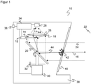
- a light transmitter 12 such as a laser in the form of an edge emitter or a VCSEL, emits a light signal that is periodically amplitude-modulated or preferably has at least one short light pulse.
- the transmitted light is collimated by transmitting optics 14 to form an emitted light beam 16, which is directed via a deflection mirror 18 and a movable deflection unit 20 into a monitoring area 22 and is remitted or reflected there by an object that may be present.
- the sensor 10 has a coaxial arrangement in which the emitted light beam 16 and the incident reflected light beam 24 travel on an optical axis. This is to be understood as an example; a biaxial arrangement is also conceivable, just as the transmission-side coupling onto the common optical axis can also be implemented differently than via the deflection mirror 18 .
- the deflection unit 20 can be designed as an oscillating mirror, but is usually a rotating mirror which rotates continuously by being driven by a motor 30 . Alternatively, no rotating mirror is provided, but the deflection unit 20 is designed as a rotating measuring head including a light transmitter 12 and a light receiver 28 .
- the respective angular position of the deflection unit 20 is detected via an encoder 32 .
- the light beam 16 or scanning beam generated by the light transmitter 12 thus sweeps over the monitoring area 22 generated by the movement. If the light receiver 28 receives a remitted light beam 24 from the monitoring area 22, the angular position of the deflection unit 20 can be adjusted using the encoder 32 to the Angular position of the object in the monitoring area 22 are closed.
- the light propagation time from the emission of the light beam 16 to the reception of the reflected light beam 24 after reflection on the object in the monitoring area 22 determined. All light-time-of-flight methods are conceivable for this purpose, in particular phase methods, pulse methods or pulse averaging methods, with pulse-based methods preferably being used in security applications.
- the distance of the object from the sensor 10 is inferred from the light propagation time using the speed of light. This evaluation takes place in an evaluation unit 34 which is connected to the light transmitter 12 , the light receiver 28 , the motor 30 and the encoder 32 for this purpose.
- Two-dimensional polar coordinates of all objects in the monitored area 22 are then available via the angle and the distance.
- Two-dimensional protective fields can thus be defined in the monitored area 22, for example, into which impermissible objects such as operators or their body parts must not reach.
- a safety-related switch-off signal is output via a safe output 36 (OSSD, Output Signal Switching Device), in order, for example, to stop a monitored dangerous machine or move it to a safe position.
- a safe output 36 (OSSD, Output Signal Switching Device)
- measurement data are output via the output 36, for example.
- a housing 38 which has a front pane 40 in the area where the light exits and enters.
- the front pane 40 is often, but not necessarily, in the form of a rotating body and does not necessarily have to extend over 360°, so that a certain angular range then remains as a dead zone. Deviating from figure 1 a curvature is also conceivable instead of a contour with a straight cross section.
- the front pane 40 is monitored for light transmission. If the transmission of light is so severely impaired that an object could be overlooked as a result, a safety-related reaction is triggered in the safety-related application of the sensor 10 .
- several test channels distributed over the circumference are provided for windscreen monitoring. This is also additionally conceivable according to the invention.
- the windscreen monitoring according to the invention which is actually to be explained, is not based on test channels but rather on an evaluation of windscreen reflections.
- a windscreen reflex can have at least two causes. On the one hand, when the emitted light beam 16 emerges, a certain proportion is reflected on the front pane 40 . This directed windscreen reflex is usually interpreted as an interference signal. That's why the windscreen is 40 in figure 1 also tilted, the directed windscreen reflex thus does not hit the light receiver 28. In other embodiments, however, the directed windscreen reflex can be guided directly, for example via a vertically positioned windscreen, or indirectly via one or more light deflectors into the light receiver 28 and used for windscreen monitoring.
- the emitted light beam 16 is scattered on the front pane 40 if there is contamination 42 there.
- the undirected scattering ensures a windshield reflection 44 which falls on the light receiver 28 via the reception path with the movable deflection unit 20 and the reception optics 26 .
- the signal from the windscreen reflex 44 is relatively weak. This is particularly true in the case of dark dust as contaminant 42. Under normal conditions, in which the sensor 10 is adjusted in its sensitivity for the detection of objects in the monitoring area 22, the front pane 40 can therefore not be reliably monitored using the front pane reflex 44.
- the sensitivity can be adjusted in various ways on the transmission or reception side, with combinations also being possible: changing the transmission power of the light transmitter 12, changing the sensitivity of the light receiver 28 in each case, in particular by changing the applied voltage, adjusting an amplification factor of an amplifier in the reception path after the light receiver 28 (VGA, Variable Gain Amplifier) or changing an analog threshold for signal sampling or a threshold in a digital signal evaluation in the control and evaluation unit 34.
- VGA Variable Gain Amplifier
- EN 62998 safety standard is designed for application-specific sensor solutions. It can be used if there is no explicitly applicable B standard, for example because it does not cover the place of use or the technology used for the solution. For certain applications, for example outdoors, EN 62998 can be fulfilled instead of IEC 61496-3.
- EN 62998 in turn allows the reliability of the sensor 10 to be limited depending on the requirement rate of the safety function. If, for example, only a few violations of the monitoring area 22 or the protective fields configured therein or other security-related violations are to be expected per day, then it is acceptable that the sensor 10 cannot perform its security function for a few seconds per day, or only to a limited extent.
- this is used to temporarily increase the sensitivity of the detection for windscreen monitoring.
- this can be done cyclically, for example by using a measurement with high sensitivity for windshield monitoring every five seconds.
- the sensitivity is preferably significantly increased, for example by a factor of two to ten or more, since the aim here is also to detect smaller effects of dark dusts or similar impurities 42 .
- the high sensitivity is retained for windscreen monitoring, for example for one or more scans or rotations of deflection unit 20, and then reset again for further measurements of objects in the monitored area.
- contamination of the front pane 40 is revealed and to this extent the requirement of IEC 61496-e is also met.
- the senor 10 also reacts very sensitively to interfering objects in the monitored area 22, such as dust particles. For this reason, no measurement results about objects are preferably generated during the windscreen monitoring obtained in the monitoring area 22, or they are discarded or marked as unreliable.
- a sensor 10 has been described with an emitted light beam 16 and thus, in the case of a laser scanner, only one monitoring plane.
- the windshield monitoring according to the invention can also be used with a multi-layer scanner.
- This is a laser scanner that has several scanning beams one above the other in elevation and thus monitors a spatial area through several levels, or more precisely with a structure similar to nested hourglasses.
- the multiple scanning beams are created by multiple light transmitters or beam splitting and are accordingly received in multiple light receivers or a light receiver with multiple receiving zones or pixels.
- a multi-layer scanner captures an object in its multiple planes, it is statistically less likely to lose detection due to local or homogeneous contamination. If additional test channels were required for the windshield monitoring with a single-layer laser scanner, fewer test channels are sufficient for a multi-layer scanner, or additional test channels can be dispensed with at the latest for a multi-layer scanner. Furthermore, it suffices to check the windshield 40 with only a portion of the multiple scanning beams.
- An advantageous special case is a dedicated scanning beam that constantly checks the front pane 40 with high sensitivity. Any measurement failures are compensated by the adjacent scanning beams, or the small measuring gap in elevation due to this dedicated scanning beam for windscreen monitoring is tolerated.
Applications Claiming Priority (1)
| Application Number | Priority Date | Filing Date | Title |
|---|---|---|---|
| DE202020120908 | 2020-08-07 |
Publications (1)
| Publication Number | Publication Date |
|---|---|
| EP3951427A1 true EP3951427A1 (fr) | 2022-02-09 |
Family
ID=76958847
Family Applications (1)
| Application Number | Title | Priority Date | Filing Date |
|---|---|---|---|
| EP21186170.3A Withdrawn EP3951427A1 (fr) | 2020-08-07 | 2021-07-16 | Capteur optoélectronique et procédé de surveillance de par-brise |
Country Status (1)
| Country | Link |
|---|---|
| EP (1) | EP3951427A1 (fr) |
Citations (12)
| Publication number | Priority date | Publication date | Assignee | Title |
|---|---|---|---|---|
| DE4340756A1 (de) | 1992-12-08 | 1994-06-09 | Sick Optik Elektronik Erwin | Laserabstandsermittlungsvorrichtung |
| DE4345446C2 (de) | 1992-12-08 | 1998-07-30 | Sick Ag | Laserabstandsermittlungsvorrichtung |
| DE19757849B4 (de) | 1997-12-24 | 2004-12-23 | Sick Ag | Scanner und Vorrichtung zur optischen Erfassung von Hindernissen, sowie deren Verwendung |
| EP2237065A1 (fr) | 2009-03-31 | 2010-10-06 | Pepperl + Fuchs GmbH | Capteur optique selon le principe de temps de vol |
| EP2388619A1 (fr) | 2010-05-20 | 2011-11-23 | Leuze electronic GmbH + Co. KG | Capteur optique |
| EP2469296B1 (fr) | 2010-12-21 | 2012-10-24 | Sick AG | Capteur optoélectronique et procédé destiné à la détection et la détermination de l'éloignement d'objets |
| EP2482094B1 (fr) | 2011-01-31 | 2013-06-12 | Sick AG | Capteur optoélectronique mesurant l'éloignement et procédé de détection d'objet |
| EP2642314A1 (fr) | 2012-03-21 | 2013-09-25 | Sick Ag | Capteur optoélectronique et procédé destiné à tester la perméabilité à la lumière d'une vitre frontale |
| DE202013102440U1 (de) | 2013-06-07 | 2014-09-08 | Sick Ag | Optische Erfassungsvorrichtung |
| EP2927711A1 (fr) | 2014-04-04 | 2015-10-07 | Sick Ag | Lecteur laser et procédé de saisie sécurisée d'objets |
| DE102015105264A1 (de) | 2015-04-08 | 2016-10-13 | Sick Ag | Optoelektronischer Sensor und Verfahren zur Transmissionsüberwachung einer Frontscheibe |
| DE102018126289A1 (de) * | 2018-10-23 | 2020-04-23 | Valeo Schalter Und Sensoren Gmbh | Verfahren zur Überprüfung der Lichtdurchlässigkeit wenigstens eines Fensters einer optischen Detektionsvorrichtung, optische Detektionsvorrichtung und Lichtdurchlässigkeitsüberprüfungseinrichtung |
-
2021
- 2021-07-16 EP EP21186170.3A patent/EP3951427A1/fr not_active Withdrawn
Patent Citations (12)
| Publication number | Priority date | Publication date | Assignee | Title |
|---|---|---|---|---|
| DE4340756A1 (de) | 1992-12-08 | 1994-06-09 | Sick Optik Elektronik Erwin | Laserabstandsermittlungsvorrichtung |
| DE4345446C2 (de) | 1992-12-08 | 1998-07-30 | Sick Ag | Laserabstandsermittlungsvorrichtung |
| DE19757849B4 (de) | 1997-12-24 | 2004-12-23 | Sick Ag | Scanner und Vorrichtung zur optischen Erfassung von Hindernissen, sowie deren Verwendung |
| EP2237065A1 (fr) | 2009-03-31 | 2010-10-06 | Pepperl + Fuchs GmbH | Capteur optique selon le principe de temps de vol |
| EP2388619A1 (fr) | 2010-05-20 | 2011-11-23 | Leuze electronic GmbH + Co. KG | Capteur optique |
| EP2469296B1 (fr) | 2010-12-21 | 2012-10-24 | Sick AG | Capteur optoélectronique et procédé destiné à la détection et la détermination de l'éloignement d'objets |
| EP2482094B1 (fr) | 2011-01-31 | 2013-06-12 | Sick AG | Capteur optoélectronique mesurant l'éloignement et procédé de détection d'objet |
| EP2642314A1 (fr) | 2012-03-21 | 2013-09-25 | Sick Ag | Capteur optoélectronique et procédé destiné à tester la perméabilité à la lumière d'une vitre frontale |
| DE202013102440U1 (de) | 2013-06-07 | 2014-09-08 | Sick Ag | Optische Erfassungsvorrichtung |
| EP2927711A1 (fr) | 2014-04-04 | 2015-10-07 | Sick Ag | Lecteur laser et procédé de saisie sécurisée d'objets |
| DE102015105264A1 (de) | 2015-04-08 | 2016-10-13 | Sick Ag | Optoelektronischer Sensor und Verfahren zur Transmissionsüberwachung einer Frontscheibe |
| DE102018126289A1 (de) * | 2018-10-23 | 2020-04-23 | Valeo Schalter Und Sensoren Gmbh | Verfahren zur Überprüfung der Lichtdurchlässigkeit wenigstens eines Fensters einer optischen Detektionsvorrichtung, optische Detektionsvorrichtung und Lichtdurchlässigkeitsüberprüfungseinrichtung |
Similar Documents
| Publication | Publication Date | Title |
|---|---|---|
| EP2927711B1 (fr) | Lecteur laser et procédé de saisie sécurisée d'objets | |
| EP3078985B1 (fr) | Capteur optoelectronique et procede de surveillance de transmission d'un disque frontal | |
| EP3355076A1 (fr) | Capteur optoélectronique et procédé de détection de l'élimination d'un objet dans une zone de surveillance | |
| DE4345446C2 (de) | Laserabstandsermittlungsvorrichtung | |
| DE102012112987B3 (de) | Optoelektronischer Sensor und Verfahren zur Erfassung und Abstandsbestimmung von Objekten | |
| DE19621120C1 (de) | Optoelektronische Vorrichtung | |
| EP3163322B1 (fr) | Scanner laser et procédé de vérification de sa capacité de fonctionnement | |
| EP2482094B1 (fr) | Capteur optoélectronique mesurant l'éloignement et procédé de détection d'objet | |
| EP1378763A1 (fr) | Appareil de balayage laser avec surveillance de fonctions | |
| EP2381268B1 (fr) | Scanner laser de sécurité | |
| EP2645125B1 (fr) | Laser scanner et procédé destiné à la détection d'objets dans une zone de surveillance | |
| DE19732776C1 (de) | Optoelektronische Vorrichtung | |
| EP3388857B1 (fr) | Dispositif de balayage laser et procédé de vérification de la capacité de fonctionnement | |
| EP3862780B1 (fr) | Balayeur laser de sécurité et procédé de surveillance de vitre frontale | |
| EP2698649B1 (fr) | Capteur de surveillance doté d'un contrôle automatique | |
| EP3699638B1 (fr) | Capteur optoélectronique et procédé de détection d'un objet | |
| EP2093731A1 (fr) | Détecteur de fumée optique linéaire doté de plusieurs rayons partiels | |
| EP2703837B1 (fr) | Scanner laser de sécurité | |
| EP3415951B1 (fr) | Capteur optique | |
| EP3951427A1 (fr) | Capteur optoélectronique et procédé de surveillance de par-brise | |
| DE102020120908A1 (de) | Optoelektronischer Sensor und Verfahren zur Frontscheibenüberwachung | |
| EP4071503B1 (fr) | Capteur optoélectronique et procédé de détection des objets | |
| DE202012105044U1 (de) | Optoelektronischer Sensor zur Erfassung und Abstandsbestimmung von Objekten | |
| EP3367129B1 (fr) | Capteur optoélectronique et procédé de détection d'objets | |
| DE202012103344U1 (de) | Sicherheits-Lichtscanner |
Legal Events
| Date | Code | Title | Description |
|---|---|---|---|
| PUAI | Public reference made under article 153(3) epc to a published international application that has entered the european phase |
Free format text: ORIGINAL CODE: 0009012 |
|
| STAA | Information on the status of an ep patent application or granted ep patent |
Free format text: STATUS: THE APPLICATION HAS BEEN PUBLISHED |
|
| AK | Designated contracting states |
Kind code of ref document: A1 Designated state(s): AL AT BE BG CH CY CZ DE DK EE ES FI FR GB GR HR HU IE IS IT LI LT LU LV MC MK MT NL NO PL PT RO RS SE SI SK SM TR |
|
| STAA | Information on the status of an ep patent application or granted ep patent |
Free format text: STATUS: REQUEST FOR EXAMINATION WAS MADE |
|
| 17P | Request for examination filed |
Effective date: 20220809 |
|
| RBV | Designated contracting states (corrected) |
Designated state(s): AL AT BE BG CH CY CZ DE DK EE ES FI FR GB GR HR HU IE IS IT LI LT LU LV MC MK MT NL NO PL PT RO RS SE SI SK SM TR |
|
| STAA | Information on the status of an ep patent application or granted ep patent |
Free format text: STATUS: THE APPLICATION IS DEEMED TO BE WITHDRAWN |
|
| 18D | Application deemed to be withdrawn |
Effective date: 20220810 |