EP2703837B1 - Scanner laser de sécurité - Google Patents
Scanner laser de sécurité Download PDFInfo
- Publication number
- EP2703837B1 EP2703837B1 EP12182737.2A EP12182737A EP2703837B1 EP 2703837 B1 EP2703837 B1 EP 2703837B1 EP 12182737 A EP12182737 A EP 12182737A EP 2703837 B1 EP2703837 B1 EP 2703837B1
- Authority
- EP
- European Patent Office
- Prior art keywords
- light
- unit
- laser scanner
- wavelengths
- safety
- Prior art date
- Legal status (The legal status is an assumption and is not a legal conclusion. Google has not performed a legal analysis and makes no representation as to the accuracy of the status listed.)
- Active
Links
- 238000001514 detection method Methods 0.000 claims description 22
- 238000011156 evaluation Methods 0.000 claims description 19
- 230000005540 biological transmission Effects 0.000 claims description 8
- 238000000034 method Methods 0.000 claims description 5
- 238000005070 sampling Methods 0.000 claims description 3
- 238000012935 Averaging Methods 0.000 claims description 2
- 238000006243 chemical reaction Methods 0.000 claims 1
- 230000000737 periodic effect Effects 0.000 claims 1
- 238000012544 monitoring process Methods 0.000 description 13
- 230000000007 visual effect Effects 0.000 description 9
- 230000001681 protective effect Effects 0.000 description 6
- 230000002123 temporal effect Effects 0.000 description 6
- 239000000428 dust Substances 0.000 description 4
- 230000003287 optical effect Effects 0.000 description 4
- 238000012360 testing method Methods 0.000 description 4
- XLYOFNOQVPJJNP-UHFFFAOYSA-N water Substances O XLYOFNOQVPJJNP-UHFFFAOYSA-N 0.000 description 4
- 238000003915 air pollution Methods 0.000 description 2
- 230000001419 dependent effect Effects 0.000 description 2
- 239000003595 mist Substances 0.000 description 2
- 230000005855 radiation Effects 0.000 description 2
- 241000196324 Embryophyta Species 0.000 description 1
- 241000183024 Populus tremula Species 0.000 description 1
- 206010047571 Visual impairment Diseases 0.000 description 1
- 230000002238 attenuated effect Effects 0.000 description 1
- 230000003750 conditioning effect Effects 0.000 description 1
- 238000011109 contamination Methods 0.000 description 1
- 239000013078 crystal Substances 0.000 description 1
- 238000011161 development Methods 0.000 description 1
- 230000006870 function Effects 0.000 description 1
- 239000007789 gas Substances 0.000 description 1
- 230000002452 interceptive effect Effects 0.000 description 1
- 238000005259 measurement Methods 0.000 description 1
- 239000002245 particle Substances 0.000 description 1
- 230000035515 penetration Effects 0.000 description 1
- 238000012545 processing Methods 0.000 description 1
- 230000004044 response Effects 0.000 description 1
- 238000012552 review Methods 0.000 description 1
- 239000002689 soil Substances 0.000 description 1
- 239000007787 solid Substances 0.000 description 1
Images

Classifications
-
- G—PHYSICS
- G01—MEASURING; TESTING
- G01S—RADIO DIRECTION-FINDING; RADIO NAVIGATION; DETERMINING DISTANCE OR VELOCITY BY USE OF RADIO WAVES; LOCATING OR PRESENCE-DETECTING BY USE OF THE REFLECTION OR RERADIATION OF RADIO WAVES; ANALOGOUS ARRANGEMENTS USING OTHER WAVES
- G01S7/00—Details of systems according to groups G01S13/00, G01S15/00, G01S17/00
- G01S7/48—Details of systems according to groups G01S13/00, G01S15/00, G01S17/00 of systems according to group G01S17/00
- G01S7/481—Constructional features, e.g. arrangements of optical elements
- G01S7/4814—Constructional features, e.g. arrangements of optical elements of transmitters alone
- G01S7/4815—Constructional features, e.g. arrangements of optical elements of transmitters alone using multiple transmitters
-
- G—PHYSICS
- G01—MEASURING; TESTING
- G01S—RADIO DIRECTION-FINDING; RADIO NAVIGATION; DETERMINING DISTANCE OR VELOCITY BY USE OF RADIO WAVES; LOCATING OR PRESENCE-DETECTING BY USE OF THE REFLECTION OR RERADIATION OF RADIO WAVES; ANALOGOUS ARRANGEMENTS USING OTHER WAVES
- G01S17/00—Systems using the reflection or reradiation of electromagnetic waves other than radio waves, e.g. lidar systems
- G01S17/02—Systems using the reflection of electromagnetic waves other than radio waves
- G01S17/06—Systems determining position data of a target
- G01S17/42—Simultaneous measurement of distance and other co-ordinates
-
- G—PHYSICS
- G01—MEASURING; TESTING
- G01S—RADIO DIRECTION-FINDING; RADIO NAVIGATION; DETERMINING DISTANCE OR VELOCITY BY USE OF RADIO WAVES; LOCATING OR PRESENCE-DETECTING BY USE OF THE REFLECTION OR RERADIATION OF RADIO WAVES; ANALOGOUS ARRANGEMENTS USING OTHER WAVES
- G01S7/00—Details of systems according to groups G01S13/00, G01S15/00, G01S17/00
- G01S7/48—Details of systems according to groups G01S13/00, G01S15/00, G01S17/00 of systems according to group G01S17/00
- G01S7/497—Means for monitoring or calibrating
-
- G—PHYSICS
- G01—MEASURING; TESTING
- G01S—RADIO DIRECTION-FINDING; RADIO NAVIGATION; DETERMINING DISTANCE OR VELOCITY BY USE OF RADIO WAVES; LOCATING OR PRESENCE-DETECTING BY USE OF THE REFLECTION OR RERADIATION OF RADIO WAVES; ANALOGOUS ARRANGEMENTS USING OTHER WAVES
- G01S17/00—Systems using the reflection or reradiation of electromagnetic waves other than radio waves, e.g. lidar systems
- G01S17/88—Lidar systems specially adapted for specific applications
- G01S17/95—Lidar systems specially adapted for specific applications for meteorological use
-
- G—PHYSICS
- G01—MEASURING; TESTING
- G01S—RADIO DIRECTION-FINDING; RADIO NAVIGATION; DETERMINING DISTANCE OR VELOCITY BY USE OF RADIO WAVES; LOCATING OR PRESENCE-DETECTING BY USE OF THE REFLECTION OR RERADIATION OF RADIO WAVES; ANALOGOUS ARRANGEMENTS USING OTHER WAVES
- G01S7/00—Details of systems according to groups G01S13/00, G01S15/00, G01S17/00
- G01S7/48—Details of systems according to groups G01S13/00, G01S15/00, G01S17/00 of systems according to group G01S17/00
- G01S7/481—Constructional features, e.g. arrangements of optical elements
- G01S7/4817—Constructional features, e.g. arrangements of optical elements relating to scanning
-
- Y—GENERAL TAGGING OF NEW TECHNOLOGICAL DEVELOPMENTS; GENERAL TAGGING OF CROSS-SECTIONAL TECHNOLOGIES SPANNING OVER SEVERAL SECTIONS OF THE IPC; TECHNICAL SUBJECTS COVERED BY FORMER USPC CROSS-REFERENCE ART COLLECTIONS [XRACs] AND DIGESTS
- Y02—TECHNOLOGIES OR APPLICATIONS FOR MITIGATION OR ADAPTATION AGAINST CLIMATE CHANGE
- Y02A—TECHNOLOGIES FOR ADAPTATION TO CLIMATE CHANGE
- Y02A90/00—Technologies having an indirect contribution to adaptation to climate change
- Y02A90/10—Information and communication technologies [ICT] supporting adaptation to climate change, e.g. for weather forecasting or climate simulation
Definitions
- the invention relates to a safety laser scanner according to the preamble of claim 1.
- a light beam generated by a laser is directed via a light deflection unit into a protected area and there remitted from an optionally present object. At least part of the remitted light passes back to the laser scanning unit and is detected there by a receiver.
- the light deflecting unit is designed to be pivotable or rotatable so that the light beam generated by the laser periodically sweeps over a protective field generated by the pivoting or rotational movement. If a light signal remitted by the object is received from the protected area, it is possible to deduce the angular position of the deflection unit from the angular position of the object in the protected area.
- the transit time of individual laser light pulses is monitored from the emission to the reception of a reflection at the object
- the angle and distance information can be used to determine the location of the object and to completely monitor the scan plane swept by the light beam. If an invalid object is located in the scan plane, a corresponding warning or stop signal can be output by the evaluation unit of the scanner.
- Such systems are used, for example, on machines in which a danger zone must be monitored, which must not be entered by an operator during operation of the machine. Is with the help of the laser scanner, the presence of an impermissible object - for example, a leg of an operator - in Danger area detected, an emergency stop of the machine is effected.
- Such scanning systems as safety sensors must work reliably and therefore have to meet high safety requirements, for example the standard EN13849 for machine safety and in particular the device standard EN61496 for non-contact protective devices (ESPE).
- Such safety laser scanners are also used on so-called FTS ("driverless transport systems") to prevent these transport systems with objects that cross their track, such. As people collide.
- FTS driverless transport systems
- external reference targets have been used in outdoor applications of laser scanners, which the laser scanner has to "see".
- the use of external targets is not only very time-consuming, because on the one hand the goals have to be provided and on the other hand the targets have to be programmed into the laser scanner. It is also hardly possible to use external targets in FTS applications, because after all, the AGV moves with the laser scanner, so that the external test targets are always seen at a different distance and direction from the laser scanner and therefore a meaningful evaluation is not possible.
- the review of an external test target is merely a "sample check" of the field of view. Other viewing angles may well be more affected in their detection capability than the direction of the external reference target.
- a laser scanner which emits light of different wavelengths in order to improve the detection quality in bad weather conditions, such as fog, snow, rain.
- bad weather conditions such as fog, snow, rain.
- a scanner operating at different wavelengths can better "detect” because fog's penetration is wavelength dependent, so the scanner has a greater "line of sight” with multiple wavelengths than with only one wavelength.
- one of the wavelengths will have a greater range than the other wavelengths.
- the US 2010/0277713 A1 describes an optical system, with the one hand, a lighting of a scene takes place and on the other hand with a further light source and other wavelength object detection with distance measurement, the objects can be a variety of things, namely vehicles, pedestrians or dust and gases.
- the DE 10 2009 028 990 A1 describes a scanner that emits light of two different wavelengths in order to better distinguish the soil of plants when scanning an agricultural area.
- hard objects is understood to mean typical objects, such as body parts, machine parts, walls, posts, or the like, which show scattering behavior for incident light, which can be approximately described using the theory of Lambertian scattering. Such objects are fundamentally safety-critical and must be recognized.
- soft Objects objects that show a scattering behavior that can best be described as the” Mie Theory.
- These soft objects are water droplets of fog, rain, or snow with diameters of the order of the wavelength of light
- Soft objects are basically uncritical, so there is no danger and the machine does not have to be stopped.
- This distinction is an essential core of the invention, because the starting point of the invention is based on the physically fundamentally different processes on which the backscattered received signals are based. While the scattering behavior of hard targets can be approximated by the theory of Lambertian scattering, the signals originating from soft targets consisting of small, spherical drops of water of diameters of the order of the wavelength used are based on Mie scattering. This results in significantly different dependencies of the temporal received signal waveform on the wavelength of the light used. While the time and also the amplitude of the received signal of a Lambertian scatterer are almost independent of the wavelength used, the Mie scattering is expected to have a significant dependence of the propagation time and the amplitude of the signal on the wavelength.
- the inventors have now recognized that, on the one hand, the presence of soft targets can thus be recognized at all and, in addition, the different scattering behavior at different wavelengths can be used to deduce the degree of visual clouding by the soft objects.
- the different scattering behavior on the soft objects on the one hand and the hard objects on the other hand can be recognized by the discriminating unit and thus a clear distinction between reflections on the "only" visual opacity (and interfering signals) causing soft objects and the reflections on the hard objects, the the scanner should actually be seen to be made.
- the scanner with the visibility detection unit can detect when the visibility cloudiness is so strong that safe object detection (hard objects) is no longer possible.
- a safety laser scanner enables active detection of visual cloudiness and improved recognition of hard objects and thus overall a substantial increase in safety in the determination of impermissible objects in the protected area. This is achieved without external test objectives, enabling mobile outdoor applications such as: FTS.
- the distinguishing unit detects different maxima and / or different edge slopes of the temporal received signal waveforms and evaluates them for reliable detection of the hard objects.
- the visibility detection unit may detect and compare maximums of the received waveforms at different wavelengths and / or detect and compare received signal levels at the same propagation time in the different received waveforms. This can be used to determine whether there is any visibility at all. It is in fact present when there are differences.
- the visibility detection unit can determine how severe the turbidity is. From this, they can determine a range of visibility and output when falling below a predetermined minimum visibility, the security signal, whereby the security is further increased.
- the different wavelengths can be generated in different ways.
- the light-emitting unit has only one light-emitting element, and the second wavelength is generated by frequency doubling.
- a second light receiver is provided and the two wavelengths are optically separated in the receiving path, for example by dichroic mirrors.
- the light-emitting unit has two light-emitting elements.
- the transmission elements are operated offset in time, so that the light pulses of the two light-emitting elements are emitted in time-division multiplex.
- the received signals are detected in a digital sampling stage so that the received signal waveforms can be stored and then evaluated.
- the invention can also be used in scanners that operate on the pulse averaging method, such. B. in the EP 2 479 586 described.
- a safety laser scanner described below serves, for example, for monitoring for unauthorized access of a monitoring area or for monitoring the area in front of an autonomously driving vehicle. If an impermissible object, for example the leg of an operator, is located in the monitoring area, this is detected by the described scanner and a safety signal, which can be a warning or a shutdown signal, is issued and appropriate measures are taken to prevent the danger, e.g. , B. the dangerous movement of the machine is stopped or at least slowed down.
- a safety signal which can be a warning or a shutdown signal
- invalid object is used in the present text for illegal objects in the protective field, which must be detected in order to avoid a hazard, eg. B. to prevent a collision. In particular, this may mean, for example, endangered body parts of operators.
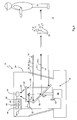
- Fig. 1 schematically shows the structure of an embodiment of a safety laser scanner 10.
- the generated by a light emitting unit 12 laser light beams 14, consisting of individual light pulses at least two different wavelengths are directed via a light deflection unit 16 in a monitoring area 18 enclosing field of view and there from a possibly existing object 19 remitted.
- the viewing area comprises the entire opening angle of the scanner 10.
- Remitted light 20 passes back to the laser scanner 10 and is detected there by the deflection unit 16 and by means of a receiving optics 22 by one (or more) light receiver 24.
- the light deflecting unit 16 is generally rotatable, with a motor 26 continuously rotating a rotating mirror 28. The respective angular position of the rotary mirror 28 is detected by an encoder 30.
- the light beams 14 generated by the light-emitting unit 12 thus cover the visual range generated by the rotational movement, in which the monitoring area 18 is located. If a received by the light receiver 24 reflected light signal 20 is received from the field of view 18, it can be concluded from the angular position of the deflection unit 30 to the angular position of the object in the field of view 18. In addition, the transit time of the individual laser light pulses of the transmitted light 14 from the emission to the reception of a reflection at the object, monitored and closed from the light transit time using the speed of light on the distance of the object from the laser scanner 10. This determines the position of the measured reflection in polar coordinates.
- This evaluation is carried out in an evaluation unit 32, which is connected to the light emitting unit 12, the light receiver 24, the motor 26 and encoder 30. With the angle and distance information, the location of the object 19 can be determined and in this way the monitoring area 18 can be completely monitored.
- the monitoring area 18 is defined in its dimensions by corresponding parameters which are stored in the evaluation unit 32 in a memory 54. If an inadmissible object 19 is located in the monitoring area 18, the evaluation unit 32 can output a corresponding object detection signal at an output of the laser scanner 10 via a line 33 and thus ultimately output a safety signal in order, for example, to bring about a stop to a dangerous machine.
- All said functional components are arranged in a housing 34 which has a front screen 36 at the front, ie in the region of the light exit and light entry.
- the front screen 36 is inclined to avoid direct reflections in the receiver, so that the angle between the light beam 14 and front screen 36 is not equal to 90 °.
- the previously described explains the basic principle and the basic structure of a laser scanner.
- the safety laser scanner according to the invention now comprises further features and properties that enable outdoor use.
- the light-emitting unit 12 is designed so that it can emit light pulses having two different wavelengths ⁇ 1 and ⁇ 2.
- two transmitting elements for example, two laser diodes have.
- the two wavelengths are indicated by different arrows, namely a wavelength ⁇ 1 as a dashed arrow 14-1 and another wavelength ⁇ 2 as a solid arrow 14-2.
- the received light 20 which is received by the light receiver 24 either as a received light 20-1 with the wavelength ⁇ 1 or as a received light 20-2 with the wavelength ⁇ 2.
- the light receiver 24 should have sufficient bandwidth to detect the light of both wavelengths.
- the receiver 24 could consist of one or two APDs (Avalanche Photo Diode).
- Fig. 2 shows two typical received signal waveforms 40-1 and 40-2 of light of different wavelengths ⁇ 1 and ⁇ 2 of an exemplary situation as in FIG Fig. 1 shown, in between the hard object to be detected 19 and the laser scanner 10 soft objects 50, z. As fog droplets, are present.
- the emitted laser pulse 14-1 with wavelength ⁇ 1 first penetrates the mist (approximately in the time interval 0 to T1) and a flat received signal 40-1 is obtained, which has a slight maximum somewhere in the interval (Mie scattering).
- T2 which corresponds to the reflection at the hard object 19
- a generally higher signal results, which in each case has steeper edges (Lambertian scattering).
- the maximum value of the reflection of the hard object can be compared with the maximum value of the fog reflection and a distinction between hard and soft reflections derived therefrom.
- a reflection usually always occurs at the end of a received signal waveform. This evaluation takes place in a discrimination unit 42 of the evaluation unit 32.
- the wavelengths ⁇ 1 and ⁇ 2 are chosen such that in the event of fog, a significant difference in the signal characteristics occurs at all. Since Mie scattering on soft objects, such as a variety of water droplets in a mist, is a very complicated and complex process (there are a variety of reflections and transmissions in each of the many and different sized droplets), it can not be determined analytically how the maxima are dependent on the wavelength. But they are usually separated and the difference in the wavelengths should be chosen so that the received signal waveforms 40-1 and 40-2 can be well distinguished.
- This detection and evaluation of the visual clouding takes place in a visual cloud determination unit 44 of the evaluation unit 32.
- the visibility determination unit 44 can output the safety signal at the output via the line 33 if it falls below a predetermined minimum visibility.
- the two transmitting elements of the light-emitting unit 12 could transmit the light pulses offset in time and receive the receiver 24 with a corresponding time offset.
- the signal conditioning then takes place via a common analog channel, the waveforms are sampled digitally in a sampling stage 46, and the digital signals of the two wavelengths compared with each other, as explained above.
- the signals of the two wavelengths can be measured separately from each other by a temporal offset and digitized, stored and subsequently processed via the same signal path.
- part of the emitted light of a single transmitter laser diode can be doubled in frequency by means of a nonlinear element.
- the two wavelengths would then be spectrally far apart (for example, 1550nm and 775nm) and the two optical signals could optically in the receive path, z. B. by dichroic mirror, separated and processed with a second adjacent to the first light receiver.
- This method has the advantage that the temporal correlation of the two signals could be used directly in the signal processing.
Claims (6)
- Scanner de sécurité à laser destiné à détecter de manière sûre et à déterminer la position d'objets (19) dans une zone de surveillance, comprenant- une unité émettrice de lumière (12), qui émet des impulsions de lumière (14-1, 14-2) avec deux longueurs d'onde différentes (λ1 et λ2),- une unité de déflexion (16) pour balayer périodiquement avec la lumière émise (14) une zone de vision du scanner (10) qui englobe la zone de surveillance (18) ;- un récepteur de lumière (24) pour préparer des signaux reçus correspondant aux impulsions de lumière émise diffusée sur les objets (50, 19) dans la zone de vision,- une unité d'évaluation (32) pour évaluer les signaux reçus et déterminer le temps de parcours de la lumière, de sorte qu'au moyen du temps de parcours de la lumière et de l'angle de rotation de l'unité de déflexion (16) il est possible de déterminer une position de la réflexion, et pour délivrer un signal de sécurité quand un objet inadmissible (19) est détecté dans la zone de surveillance (18),- et l'unité d'évaluation (32) inclut une unité de reconnaissance de voilage de vision (44) qui est réalisée pour détecter des évolutions temporelles différentes (40-1 et 40-2) et pour reconnaître un voilage de vision à partir d'une comparaison des évolutions,- et l'unité d'évaluation (32) inclut une unité de différenciation (42) qui différencie les signaux reçus provenant de réflexions sur des objets inadmissibles (19) et les signaux reçus provenant de diffusions sur les objets (50),
caractérisé en ce que- les impulsions de lumière sont émises par deux éléments émetteurs de lumière de manière décalée dans le temps,- deux récepteurs de lumière sont prévus dans le trajet de réception pour la détection des deux longueurs d'onde, et- les deux longueurs d'onde (λ1 et λ2) sont choisies de telle façon que pour un même angle de rotation de l'unité de déflexion (16), les signaux reçus correspondant aux deux longueurs d'onde présentent, en cas de diffusion sur des objets (50) provoquant un voilage de vision, des maxima différents et/ou des pentes de flanc différentes dans une évolution temporelle des signaux reçus (40-1 et 40-2). - Scanner de sécurité à laser selon l'une des revendications précédentes, caractérisé en ce que l'unité de reconnaissance de voilage de vision est capable de détecter et de comparer des évolutions différentes des signaux reçus, et/ou de détecter et de comparer des intensités des signaux reçus pour le même temps de parcours dans les différentes évolutions.
- Scanner de sécurité à laser selon l'une des revendications précédentes, caractérisé en ce que l'unité de reconnaissance de voilage de vision est capable de déterminer une distance de vision et de délivrer le signal de sécurité lors du passage au-dessous d'une distance de vision minimale prédéterminée.
- Scanner de sécurité à laser selon l'une des revendications précédentes, caractérisé en ce que l'unité émettrice de lumière comprend un seul élément émetteur de lumière, et la seconde longueur d'onde est préparée par conversion de fréquence, et les deux longueurs d'onde sont séparées dans le trajet de réception (par exemple miroir dichroïque).
- Scanner de sécurité à laser selon l'une des revendications précédentes, caractérisé en ce que les signaux reçus sont exploités dans un étage d'échantillonnage numérique.
- Scanner de sécurité à laser selon l'une des revendications précédentes, caractérisé en ce que le scanner fonctionne d'après le principe du moyennage d'impulsions.
Priority Applications (1)
| Application Number | Priority Date | Filing Date | Title |
|---|---|---|---|
| EP12182737.2A EP2703837B1 (fr) | 2012-09-03 | 2012-09-03 | Scanner laser de sécurité |
Applications Claiming Priority (1)
| Application Number | Priority Date | Filing Date | Title |
|---|---|---|---|
| EP12182737.2A EP2703837B1 (fr) | 2012-09-03 | 2012-09-03 | Scanner laser de sécurité |
Publications (2)
| Publication Number | Publication Date |
|---|---|
| EP2703837A1 EP2703837A1 (fr) | 2014-03-05 |
| EP2703837B1 true EP2703837B1 (fr) | 2014-07-16 |
Family
ID=46785295
Family Applications (1)
| Application Number | Title | Priority Date | Filing Date |
|---|---|---|---|
| EP12182737.2A Active EP2703837B1 (fr) | 2012-09-03 | 2012-09-03 | Scanner laser de sécurité |
Country Status (1)
| Country | Link |
|---|---|
| EP (1) | EP2703837B1 (fr) |
Cited By (2)
| Publication number | Priority date | Publication date | Assignee | Title |
|---|---|---|---|---|
| DE102016115201A1 (de) | 2016-08-16 | 2018-02-22 | Sick Ag | Verfahren zum Betreiben eines Überwachungssensors und Überwachungssensor |
| US11417111B2 (en) | 2017-12-22 | 2022-08-16 | Terra Scientia, Llc | Method, system and material for detecting objects of high interest with laser scanning systems |
Families Citing this family (2)
| Publication number | Priority date | Publication date | Assignee | Title |
|---|---|---|---|---|
| US11221399B2 (en) | 2018-12-12 | 2022-01-11 | Waymo Llc | Detecting spurious objects for autonomous vehicles |
| DE102021112709B4 (de) | 2021-05-17 | 2023-06-22 | Triple-In Holding Ag | LiDAR Laser-Scanner |
Citations (1)
| Publication number | Priority date | Publication date | Assignee | Title |
|---|---|---|---|---|
| DE102009028990A1 (de) * | 2009-04-03 | 2010-10-07 | Robert Bosch Gmbh | Verfahren und System für die Umfelderfassung |
Family Cites Families (5)
| Publication number | Priority date | Publication date | Assignee | Title |
|---|---|---|---|---|
| DE4340756C5 (de) | 1992-12-08 | 2006-08-10 | Sick Ag | Laserabstandsermittlungsvorrichtung |
| DE102005049471B4 (de) | 2005-10-13 | 2007-09-13 | Ingenieurbüro Spies GbR (vertretungsberechtigte Gesellschafter: Hans Spies, Martin Spies, 86558 Hohenwart) | Entfernungssensor mit Einzelflächenabtastung |
| CA2857826C (fr) * | 2007-12-21 | 2015-03-17 | Leddartech Inc. | Procedes et systemes de detection et de telemetrie |
| DE102009049809B4 (de) | 2008-04-18 | 2019-10-10 | Ingenieurbüro Spies GbR (vertretungsberechtigte Gesellschafter: Hans Spies, Martin Spies, 86558 Hohenwart) | Optischer Laufzeitsensor zur Raumabtastung |
| EP2479586B1 (fr) | 2011-01-19 | 2014-03-19 | Sick AG | Procédé destiné à l'évaluation d'un degré d'impureté d'un disque frontal d'un dispositif de saisie optique et dispositif de saisie optique |
-
2012
- 2012-09-03 EP EP12182737.2A patent/EP2703837B1/fr active Active
Patent Citations (1)
| Publication number | Priority date | Publication date | Assignee | Title |
|---|---|---|---|---|
| DE102009028990A1 (de) * | 2009-04-03 | 2010-10-07 | Robert Bosch Gmbh | Verfahren und System für die Umfelderfassung |
Cited By (2)
| Publication number | Priority date | Publication date | Assignee | Title |
|---|---|---|---|---|
| DE102016115201A1 (de) | 2016-08-16 | 2018-02-22 | Sick Ag | Verfahren zum Betreiben eines Überwachungssensors und Überwachungssensor |
| US11417111B2 (en) | 2017-12-22 | 2022-08-16 | Terra Scientia, Llc | Method, system and material for detecting objects of high interest with laser scanning systems |
Also Published As
| Publication number | Publication date |
|---|---|
| EP2703837A1 (fr) | 2014-03-05 |
Similar Documents
| Publication | Publication Date | Title |
|---|---|---|
| EP2722684B1 (fr) | Lecteur laser | |
| EP2824478B1 (fr) | Capteur optoélectronique et procédé destiné à la détection d'objets et à la détermination de distance dans une zone de surveillance | |
| EP2541273B1 (fr) | Détection et détermination de distance d'objets | |
| DE4340756C5 (de) | Laserabstandsermittlungsvorrichtung | |
| DE102009057104B4 (de) | Entfernungsmessender Laserscanner | |
| DE102012112987B3 (de) | Optoelektronischer Sensor und Verfahren zur Erfassung und Abstandsbestimmung von Objekten | |
| EP3435117B1 (fr) | Capteur et procédé de détection et de détermination des distances entre des objets | |
| DE4345446C2 (de) | Laserabstandsermittlungsvorrichtung | |
| EP3078985B1 (fr) | Capteur optoelectronique et procede de surveillance de transmission d'un disque frontal | |
| DE202012010014U1 (de) | Laserscanner | |
| EP3220164B1 (fr) | Procédé de fonctionnement d'un capteur écartométrique de surveillance et capteur écartométrique de surveillance | |
| EP2703837B1 (fr) | Scanner laser de sécurité | |
| EP2381268A1 (fr) | Scanner laser de sécurité | |
| EP3862780B1 (fr) | Balayeur laser de sécurité et procédé de surveillance de vitre frontale | |
| EP3287809B1 (fr) | Procédé de fonctionnement d'un dispositif de baleyage et dispositif de baleyage | |
| EP2093731A1 (fr) | Détecteur de fumée optique linéaire doté de plusieurs rayons partiels | |
| EP2682780A1 (fr) | Procédé de détection et de détermination de position sécurisée d'objets et dispositif de sécurité | |
| DE102017125587A1 (de) | Optischer Sensor zum Nachweis von Objekten in einem Erfassungsbereich | |
| EP3588139B1 (fr) | Capteur optoélectronique et procédé de détermination de la distance | |
| DE102018126592B4 (de) | Verfahren zur Erkennung von Durchlässigkeitsstörungen in Bezug auf Licht wenigstens eines Fensters eines Gehäuses einer optischen Detektionsvorrichtung und optische Detektionsvorrichtung | |
| DE202012103344U1 (de) | Sicherheits-Lichtscanner | |
| DE202012105044U1 (de) | Optoelektronischer Sensor zur Erfassung und Abstandsbestimmung von Objekten | |
| EP2515143A1 (fr) | Procédé de détection et de détermination de position sécurisée d'objets et dispositif de sécurité | |
| DE10313709B4 (de) | Optischer Sensor | |
| DE102013018800A1 (de) | Verfahren und Vorrichtung zum optischen Bestimmen von Abständen zu Objekten in einem Überwachungsbereich, insbesondere in einem Überwachungsbereich von automatischen Türen |
Legal Events
| Date | Code | Title | Description |
|---|---|---|---|
| 17P | Request for examination filed |
Effective date: 20130408 |
|
| AK | Designated contracting states |
Kind code of ref document: A1 Designated state(s): AL AT BE BG CH CY CZ DE DK EE ES FI FR GB GR HR HU IE IS IT LI LT LU LV MC MK MT NL NO PL PT RO RS SE SI SK SM TR |
|
| AX | Request for extension of the european patent |
Extension state: BA ME |
|
| PUAI | Public reference made under article 153(3) epc to a published international application that has entered the european phase |
Free format text: ORIGINAL CODE: 0009012 |
|
| GRAP | Despatch of communication of intention to grant a patent |
Free format text: ORIGINAL CODE: EPIDOSNIGR1 |
|
| INTG | Intention to grant announced |
Effective date: 20140424 |
|
| GRAS | Grant fee paid |
Free format text: ORIGINAL CODE: EPIDOSNIGR3 |
|
| GRAA | (expected) grant |
Free format text: ORIGINAL CODE: 0009210 |
|
| AK | Designated contracting states |
Kind code of ref document: B1 Designated state(s): AL AT BE BG CH CY CZ DE DK EE ES FI FR GB GR HR HU IE IS IT LI LT LU LV MC MK MT NL NO PL PT RO RS SE SI SK SM TR |
|
| REG | Reference to a national code |
Ref country code: GB Ref legal event code: FG4D Free format text: NOT ENGLISH |
|
| REG | Reference to a national code |
Ref country code: CH Ref legal event code: EP |
|
| REG | Reference to a national code |
Ref country code: IE Ref legal event code: FG4D Free format text: LANGUAGE OF EP DOCUMENT: GERMAN |
|
| REG | Reference to a national code |
Ref country code: AT Ref legal event code: REF Ref document number: 677959 Country of ref document: AT Kind code of ref document: T Effective date: 20140815 |
|
| REG | Reference to a national code |
Ref country code: DE Ref legal event code: R096 Ref document number: 502012001012 Country of ref document: DE Effective date: 20140828 |
|
| REG | Reference to a national code |
Ref country code: NL Ref legal event code: VDEP Effective date: 20140716 |
|
| REG | Reference to a national code |
Ref country code: LT Ref legal event code: MG4D |
|
| PG25 | Lapsed in a contracting state [announced via postgrant information from national office to epo] |
Ref country code: NO Free format text: LAPSE BECAUSE OF FAILURE TO SUBMIT A TRANSLATION OF THE DESCRIPTION OR TO PAY THE FEE WITHIN THE PRESCRIBED TIME-LIMIT Effective date: 20141016 Ref country code: PT Free format text: LAPSE BECAUSE OF FAILURE TO SUBMIT A TRANSLATION OF THE DESCRIPTION OR TO PAY THE FEE WITHIN THE PRESCRIBED TIME-LIMIT Effective date: 20141117 Ref country code: FI Free format text: LAPSE BECAUSE OF FAILURE TO SUBMIT A TRANSLATION OF THE DESCRIPTION OR TO PAY THE FEE WITHIN THE PRESCRIBED TIME-LIMIT Effective date: 20140716 Ref country code: BG Free format text: LAPSE BECAUSE OF FAILURE TO SUBMIT A TRANSLATION OF THE DESCRIPTION OR TO PAY THE FEE WITHIN THE PRESCRIBED TIME-LIMIT Effective date: 20141016 Ref country code: ES Free format text: LAPSE BECAUSE OF FAILURE TO SUBMIT A TRANSLATION OF THE DESCRIPTION OR TO PAY THE FEE WITHIN THE PRESCRIBED TIME-LIMIT Effective date: 20140716 Ref country code: GR Free format text: LAPSE BECAUSE OF FAILURE TO SUBMIT A TRANSLATION OF THE DESCRIPTION OR TO PAY THE FEE WITHIN THE PRESCRIBED TIME-LIMIT Effective date: 20141017 Ref country code: SE Free format text: LAPSE BECAUSE OF FAILURE TO SUBMIT A TRANSLATION OF THE DESCRIPTION OR TO PAY THE FEE WITHIN THE PRESCRIBED TIME-LIMIT Effective date: 20140716 Ref country code: LT Free format text: LAPSE BECAUSE OF FAILURE TO SUBMIT A TRANSLATION OF THE DESCRIPTION OR TO PAY THE FEE WITHIN THE PRESCRIBED TIME-LIMIT Effective date: 20140716 |
|
| PG25 | Lapsed in a contracting state [announced via postgrant information from national office to epo] |
Ref country code: NL Free format text: LAPSE BECAUSE OF FAILURE TO SUBMIT A TRANSLATION OF THE DESCRIPTION OR TO PAY THE FEE WITHIN THE PRESCRIBED TIME-LIMIT Effective date: 20140716 Ref country code: CY Free format text: LAPSE BECAUSE OF FAILURE TO SUBMIT A TRANSLATION OF THE DESCRIPTION OR TO PAY THE FEE WITHIN THE PRESCRIBED TIME-LIMIT Effective date: 20140716 Ref country code: LV Free format text: LAPSE BECAUSE OF FAILURE TO SUBMIT A TRANSLATION OF THE DESCRIPTION OR TO PAY THE FEE WITHIN THE PRESCRIBED TIME-LIMIT Effective date: 20140716 Ref country code: IS Free format text: LAPSE BECAUSE OF FAILURE TO SUBMIT A TRANSLATION OF THE DESCRIPTION OR TO PAY THE FEE WITHIN THE PRESCRIBED TIME-LIMIT Effective date: 20141116 Ref country code: RS Free format text: LAPSE BECAUSE OF FAILURE TO SUBMIT A TRANSLATION OF THE DESCRIPTION OR TO PAY THE FEE WITHIN THE PRESCRIBED TIME-LIMIT Effective date: 20140716 Ref country code: PL Free format text: LAPSE BECAUSE OF FAILURE TO SUBMIT A TRANSLATION OF THE DESCRIPTION OR TO PAY THE FEE WITHIN THE PRESCRIBED TIME-LIMIT Effective date: 20140716 |
|
| REG | Reference to a national code |
Ref country code: DE Ref legal event code: R097 Ref document number: 502012001012 Country of ref document: DE |
|
| PG25 | Lapsed in a contracting state [announced via postgrant information from national office to epo] |
Ref country code: RO Free format text: LAPSE BECAUSE OF FAILURE TO SUBMIT A TRANSLATION OF THE DESCRIPTION OR TO PAY THE FEE WITHIN THE PRESCRIBED TIME-LIMIT Effective date: 20140716 Ref country code: IT Free format text: LAPSE BECAUSE OF FAILURE TO SUBMIT A TRANSLATION OF THE DESCRIPTION OR TO PAY THE FEE WITHIN THE PRESCRIBED TIME-LIMIT Effective date: 20140716 Ref country code: EE Free format text: LAPSE BECAUSE OF FAILURE TO SUBMIT A TRANSLATION OF THE DESCRIPTION OR TO PAY THE FEE WITHIN THE PRESCRIBED TIME-LIMIT Effective date: 20140716 Ref country code: DK Free format text: LAPSE BECAUSE OF FAILURE TO SUBMIT A TRANSLATION OF THE DESCRIPTION OR TO PAY THE FEE WITHIN THE PRESCRIBED TIME-LIMIT Effective date: 20140716 Ref country code: CZ Free format text: LAPSE BECAUSE OF FAILURE TO SUBMIT A TRANSLATION OF THE DESCRIPTION OR TO PAY THE FEE WITHIN THE PRESCRIBED TIME-LIMIT Effective date: 20140716 Ref country code: LU Free format text: LAPSE BECAUSE OF FAILURE TO SUBMIT A TRANSLATION OF THE DESCRIPTION OR TO PAY THE FEE WITHIN THE PRESCRIBED TIME-LIMIT Effective date: 20140903 Ref country code: SK Free format text: LAPSE BECAUSE OF FAILURE TO SUBMIT A TRANSLATION OF THE DESCRIPTION OR TO PAY THE FEE WITHIN THE PRESCRIBED TIME-LIMIT Effective date: 20140716 Ref country code: MC Free format text: LAPSE BECAUSE OF FAILURE TO SUBMIT A TRANSLATION OF THE DESCRIPTION OR TO PAY THE FEE WITHIN THE PRESCRIBED TIME-LIMIT Effective date: 20140716 |
|
| PLBE | No opposition filed within time limit |
Free format text: ORIGINAL CODE: 0009261 |
|
| STAA | Information on the status of an ep patent application or granted ep patent |
Free format text: STATUS: NO OPPOSITION FILED WITHIN TIME LIMIT |
|
| REG | Reference to a national code |
Ref country code: IE Ref legal event code: MM4A |
|
| 26N | No opposition filed |
Effective date: 20150417 |
|
| PG25 | Lapsed in a contracting state [announced via postgrant information from national office to epo] |
Ref country code: BE Free format text: LAPSE BECAUSE OF NON-PAYMENT OF DUE FEES Effective date: 20140930 |
|
| PG25 | Lapsed in a contracting state [announced via postgrant information from national office to epo] |
Ref country code: IE Free format text: LAPSE BECAUSE OF NON-PAYMENT OF DUE FEES Effective date: 20140903 |
|
| PG25 | Lapsed in a contracting state [announced via postgrant information from national office to epo] |
Ref country code: SI Free format text: LAPSE BECAUSE OF FAILURE TO SUBMIT A TRANSLATION OF THE DESCRIPTION OR TO PAY THE FEE WITHIN THE PRESCRIBED TIME-LIMIT Effective date: 20140716 |
|
| PG25 | Lapsed in a contracting state [announced via postgrant information from national office to epo] |
Ref country code: SM Free format text: LAPSE BECAUSE OF FAILURE TO SUBMIT A TRANSLATION OF THE DESCRIPTION OR TO PAY THE FEE WITHIN THE PRESCRIBED TIME-LIMIT Effective date: 20140716 |
|
| PG25 | Lapsed in a contracting state [announced via postgrant information from national office to epo] |
Ref country code: MT Free format text: LAPSE BECAUSE OF FAILURE TO SUBMIT A TRANSLATION OF THE DESCRIPTION OR TO PAY THE FEE WITHIN THE PRESCRIBED TIME-LIMIT Effective date: 20140716 |
|
| PG25 | Lapsed in a contracting state [announced via postgrant information from national office to epo] |
Ref country code: HR Free format text: LAPSE BECAUSE OF FAILURE TO SUBMIT A TRANSLATION OF THE DESCRIPTION OR TO PAY THE FEE WITHIN THE PRESCRIBED TIME-LIMIT Effective date: 20140716 Ref country code: HU Free format text: LAPSE BECAUSE OF FAILURE TO SUBMIT A TRANSLATION OF THE DESCRIPTION OR TO PAY THE FEE WITHIN THE PRESCRIBED TIME-LIMIT; INVALID AB INITIO Effective date: 20120903 |
|
| REG | Reference to a national code |
Ref country code: FR Ref legal event code: PLFP Year of fee payment: 5 |
|
| PG25 | Lapsed in a contracting state [announced via postgrant information from national office to epo] |
Ref country code: TR Free format text: LAPSE BECAUSE OF FAILURE TO SUBMIT A TRANSLATION OF THE DESCRIPTION OR TO PAY THE FEE WITHIN THE PRESCRIBED TIME-LIMIT Effective date: 20140716 |
|
| REG | Reference to a national code |
Ref country code: FR Ref legal event code: PLFP Year of fee payment: 6 |
|
| PG25 | Lapsed in a contracting state [announced via postgrant information from national office to epo] |
Ref country code: MK Free format text: LAPSE BECAUSE OF FAILURE TO SUBMIT A TRANSLATION OF THE DESCRIPTION OR TO PAY THE FEE WITHIN THE PRESCRIBED TIME-LIMIT Effective date: 20140716 |
|
| REG | Reference to a national code |
Ref country code: FR Ref legal event code: PLFP Year of fee payment: 7 |
|
| PG25 | Lapsed in a contracting state [announced via postgrant information from national office to epo] |
Ref country code: AL Free format text: LAPSE BECAUSE OF FAILURE TO SUBMIT A TRANSLATION OF THE DESCRIPTION OR TO PAY THE FEE WITHIN THE PRESCRIBED TIME-LIMIT Effective date: 20140716 |
|
| REG | Reference to a national code |
Ref country code: AT Ref legal event code: MM01 Ref document number: 677959 Country of ref document: AT Kind code of ref document: T Effective date: 20170903 |
|
| PG25 | Lapsed in a contracting state [announced via postgrant information from national office to epo] |
Ref country code: AT Free format text: LAPSE BECAUSE OF NON-PAYMENT OF DUE FEES Effective date: 20170903 |
|
| PGFP | Annual fee paid to national office [announced via postgrant information from national office to epo] |
Ref country code: CH Payment date: 20190924 Year of fee payment: 8 |
|
| REG | Reference to a national code |
Ref country code: CH Ref legal event code: PL |
|
| PG25 | Lapsed in a contracting state [announced via postgrant information from national office to epo] |
Ref country code: LI Free format text: LAPSE BECAUSE OF NON-PAYMENT OF DUE FEES Effective date: 20200930 Ref country code: CH Free format text: LAPSE BECAUSE OF NON-PAYMENT OF DUE FEES Effective date: 20200930 |
|
| PGFP | Annual fee paid to national office [announced via postgrant information from national office to epo] |
Ref country code: GB Payment date: 20230921 Year of fee payment: 12 |
|
| PGFP | Annual fee paid to national office [announced via postgrant information from national office to epo] |
Ref country code: FR Payment date: 20230919 Year of fee payment: 12 Ref country code: DE Payment date: 20230919 Year of fee payment: 12 |