EP3059608B1 - Capteur optoélectronique et procédé destiné à la détection d'objets - Google Patents
Capteur optoélectronique et procédé destiné à la détection d'objets Download PDFInfo
- Publication number
- EP3059608B1 EP3059608B1 EP15155879.8A EP15155879A EP3059608B1 EP 3059608 B1 EP3059608 B1 EP 3059608B1 EP 15155879 A EP15155879 A EP 15155879A EP 3059608 B1 EP3059608 B1 EP 3059608B1
- Authority
- EP
- European Patent Office
- Prior art keywords
- light
- signal
- reception
- reception level
- sensor
- Prior art date
- Legal status (The legal status is an assumption and is not a legal conclusion. Google has not performed a legal analysis and makes no representation as to the accuracy of the status listed.)
- Active
Links
- 238000000034 method Methods 0.000 title claims description 32
- 230000005693 optoelectronics Effects 0.000 title claims description 6
- 238000011156 evaluation Methods 0.000 claims description 39
- 238000005259 measurement Methods 0.000 claims description 30
- 238000012937 correction Methods 0.000 claims description 11
- 238000012544 monitoring process Methods 0.000 claims description 10
- 238000001514 detection method Methods 0.000 claims description 9
- 238000012360 testing method Methods 0.000 claims description 9
- 239000003990 capacitor Substances 0.000 claims description 2
- 238000001914 filtration Methods 0.000 claims description 2
- 238000002366 time-of-flight method Methods 0.000 claims 4
- 238000012935 Averaging Methods 0.000 description 11
- 238000005516 engineering process Methods 0.000 description 6
- 230000003287 optical effect Effects 0.000 description 6
- 238000007781 pre-processing Methods 0.000 description 6
- 230000008901 benefit Effects 0.000 description 5
- 230000008859 change Effects 0.000 description 3
- 230000001681 protective effect Effects 0.000 description 3
- 230000002123 temporal effect Effects 0.000 description 3
- 238000010586 diagram Methods 0.000 description 2
- 230000008569 process Effects 0.000 description 2
- 238000005070 sampling Methods 0.000 description 2
- 241000183024 Populus tremula Species 0.000 description 1
- 230000004913 activation Effects 0.000 description 1
- 230000003321 amplification Effects 0.000 description 1
- 238000013459 approach Methods 0.000 description 1
- 230000004888 barrier function Effects 0.000 description 1
- 230000005540 biological transmission Effects 0.000 description 1
- 238000004891 communication Methods 0.000 description 1
- 230000000295 complement effect Effects 0.000 description 1
- 238000011109 contamination Methods 0.000 description 1
- 238000012986 modification Methods 0.000 description 1
- 230000004048 modification Effects 0.000 description 1
- 238000003199 nucleic acid amplification method Methods 0.000 description 1
- 230000010355 oscillation Effects 0.000 description 1
- 230000010363 phase shift Effects 0.000 description 1
- 238000012545 processing Methods 0.000 description 1
- 230000035945 sensitivity Effects 0.000 description 1
- 230000007704 transition Effects 0.000 description 1
Images

Classifications
-
- G—PHYSICS
- G01—MEASURING; TESTING
- G01S—RADIO DIRECTION-FINDING; RADIO NAVIGATION; DETERMINING DISTANCE OR VELOCITY BY USE OF RADIO WAVES; LOCATING OR PRESENCE-DETECTING BY USE OF THE REFLECTION OR RERADIATION OF RADIO WAVES; ANALOGOUS ARRANGEMENTS USING OTHER WAVES
- G01S7/00—Details of systems according to groups G01S13/00, G01S15/00, G01S17/00
- G01S7/48—Details of systems according to groups G01S13/00, G01S15/00, G01S17/00 of systems according to group G01S17/00
- G01S7/483—Details of pulse systems
- G01S7/484—Transmitters
-
- G—PHYSICS
- G01—MEASURING; TESTING
- G01S—RADIO DIRECTION-FINDING; RADIO NAVIGATION; DETERMINING DISTANCE OR VELOCITY BY USE OF RADIO WAVES; LOCATING OR PRESENCE-DETECTING BY USE OF THE REFLECTION OR RERADIATION OF RADIO WAVES; ANALOGOUS ARRANGEMENTS USING OTHER WAVES
- G01S17/00—Systems using the reflection or reradiation of electromagnetic waves other than radio waves, e.g. lidar systems
- G01S17/02—Systems using the reflection of electromagnetic waves other than radio waves
- G01S17/06—Systems determining position data of a target
- G01S17/08—Systems determining position data of a target for measuring distance only
- G01S17/10—Systems determining position data of a target for measuring distance only using transmission of interrupted, pulse-modulated waves
-
- G—PHYSICS
- G01—MEASURING; TESTING
- G01S—RADIO DIRECTION-FINDING; RADIO NAVIGATION; DETERMINING DISTANCE OR VELOCITY BY USE OF RADIO WAVES; LOCATING OR PRESENCE-DETECTING BY USE OF THE REFLECTION OR RERADIATION OF RADIO WAVES; ANALOGOUS ARRANGEMENTS USING OTHER WAVES
- G01S17/00—Systems using the reflection or reradiation of electromagnetic waves other than radio waves, e.g. lidar systems
- G01S17/02—Systems using the reflection of electromagnetic waves other than radio waves
- G01S17/06—Systems determining position data of a target
- G01S17/42—Simultaneous measurement of distance and other co-ordinates
-
- G—PHYSICS
- G01—MEASURING; TESTING
- G01S—RADIO DIRECTION-FINDING; RADIO NAVIGATION; DETERMINING DISTANCE OR VELOCITY BY USE OF RADIO WAVES; LOCATING OR PRESENCE-DETECTING BY USE OF THE REFLECTION OR RERADIATION OF RADIO WAVES; ANALOGOUS ARRANGEMENTS USING OTHER WAVES
- G01S7/00—Details of systems according to groups G01S13/00, G01S15/00, G01S17/00
- G01S7/48—Details of systems according to groups G01S13/00, G01S15/00, G01S17/00 of systems according to group G01S17/00
- G01S7/483—Details of pulse systems
- G01S7/486—Receivers
- G01S7/4861—Circuits for detection, sampling, integration or read-out
-
- G—PHYSICS
- G01—MEASURING; TESTING
- G01S—RADIO DIRECTION-FINDING; RADIO NAVIGATION; DETERMINING DISTANCE OR VELOCITY BY USE OF RADIO WAVES; LOCATING OR PRESENCE-DETECTING BY USE OF THE REFLECTION OR RERADIATION OF RADIO WAVES; ANALOGOUS ARRANGEMENTS USING OTHER WAVES
- G01S7/00—Details of systems according to groups G01S13/00, G01S15/00, G01S17/00
- G01S7/48—Details of systems according to groups G01S13/00, G01S15/00, G01S17/00 of systems according to group G01S17/00
- G01S7/483—Details of pulse systems
- G01S7/486—Receivers
- G01S7/4865—Time delay measurement, e.g. time-of-flight measurement, time of arrival measurement or determining the exact position of a peak
-
- G—PHYSICS
- G01—MEASURING; TESTING
- G01S—RADIO DIRECTION-FINDING; RADIO NAVIGATION; DETERMINING DISTANCE OR VELOCITY BY USE OF RADIO WAVES; LOCATING OR PRESENCE-DETECTING BY USE OF THE REFLECTION OR RERADIATION OF RADIO WAVES; ANALOGOUS ARRANGEMENTS USING OTHER WAVES
- G01S7/00—Details of systems according to groups G01S13/00, G01S15/00, G01S17/00
- G01S7/48—Details of systems according to groups G01S13/00, G01S15/00, G01S17/00 of systems according to group G01S17/00
- G01S7/497—Means for monitoring or calibrating
-
- G—PHYSICS
- G01—MEASURING; TESTING
- G01S—RADIO DIRECTION-FINDING; RADIO NAVIGATION; DETERMINING DISTANCE OR VELOCITY BY USE OF RADIO WAVES; LOCATING OR PRESENCE-DETECTING BY USE OF THE REFLECTION OR RERADIATION OF RADIO WAVES; ANALOGOUS ARRANGEMENTS USING OTHER WAVES
- G01S7/00—Details of systems according to groups G01S13/00, G01S15/00, G01S17/00
- G01S7/48—Details of systems according to groups G01S13/00, G01S15/00, G01S17/00 of systems according to group G01S17/00
- G01S7/4802—Details of systems according to groups G01S13/00, G01S15/00, G01S17/00 of systems according to group G01S17/00 using analysis of echo signal for target characterisation; Target signature; Target cross-section
Definitions
- the invention relates to an optoelectronic sensor and a method for detecting objects in a surveillance area according to the preamble of claim 1 or 10.
- a common task in the detection of objects with an optoelectronic sensor is the distance determination.
- have long been known light transit time method in which light signals are emitted and the time is measured to receive the remitted or reflected on objects light signals. Due to the constant propagation speed of the signal, the signal transit time can be converted directly into a distance.
- Precondition for an accurate signal propagation time measurement is the precise determination of the reception time.
- various methods are known.
- a phase method a periodically modulated signal is transmitted and the phase shift between transmitted and received signals is determined.
- a pulse method uses a signal that allows accurate timing. The detection takes place in the simplest case by comparator thresholds, in more complex processes, the entire received signal is sampled and evaluated digitally to locate the received pulse.
- a pulse averaging method transmits a plurality of transmit pulses and statistically evaluates the subsequently received pulses.
- a particularly efficient and accurate averaging method for a one-dimensional range finder is used in the DE 10 2007 013 714 A1 presented.
- the WO 2012 084 298 A1 deals with a corresponding laser scanner.
- the reception level fluctuates mainly because of two influencing factors considerably, namely the remission degree of the touched object and the object distance.
- the remission level can be in the range of a few percent for a black target, or even over one hundred percent for a retro-reflector.
- the reception level drops quadratically over the distance in the case of a Lambertian target. This results in a dynamic range that spans many orders of magnitude.
- a color or level correction of the measured distance is usually made as a function of the actual reflectance of a detected object, but which presupposes that the reception level is known.
- a corresponding level measurement would require a sampling of the received signal at least with a plurality of thresholds or an A / D converter with sufficient bit depth, but in contrast to conventional simple threshold methods or to the binarization-based pulse averaging method according to FIG DE 10 2007 013 714 A1 are technically complex.
- the dynamic range is divided into several receive channels with complementary gain ranges.
- it means a significant increase in hardware costs, if at least two receiving channels with high temporal resolution must be scanned.
- an optoelectronic sensor and a method for detecting objects in a surveillance area according to claim 1 or 10.
- the sensor emits a light signal in the usual way, converts the returning light signal in a light receiver, in particular an APD (avalanche photo diode), into an electrical received signal and evaluates it.
- APD avalanche photo diode
- the invention is based on the basic idea, while also determining the reception level, specifically not from the received signal of the light receiver. Instead, a measurement information in a regularly provided anyway additional circuit for the operation of the light receiver is used to determine the reception level.
- the invention has the advantage that the dynamic range is extended in a particularly cost-effective manner. It is possible in the additional circuit with very simple means to obtain measurement information from which the reception level can be determined. The actual measurement in the receiving channel based on the signal of the light receiver remains completely unaffected, but can of course be corrected on the basis of the reception level and thus improved in their accuracy.
- the additional circuit preferably has a voltage supply of the light receiver.
- a voltage supply of the light receiver in particular, in the case of an APD as a light receiver is a high voltage power supply.
- the stress of this voltage supply is then preferably obtained during the reception of light signals.
- the additional circuit preferably has a capacitor for providing charge for pulse responses of the light receiver.
- This parallel capacitance thus provides the necessary energy for pulse responses in a single pulse method or a pulse averaging method.
- the charge flowing out during the reception of light signals or the corresponding current is preferably measured as measurement information.
- the evaluation unit is preferably designed to compare the reception level with an expected reception level of a reflector. That can for example be done by a threshold comparison with a threshold that is set or learned using a typical reflector signal. It is then conceivable to determine the reception level only in a binary manner, namely whether the object being touched is a reflector or not. Incidentally, this can also be valuable object information on its own, which is output or otherwise used, for example if reflectors are used as markers.
- a current measuring unit is preferably connected to the additional circuit.
- the measurement information from which the reception level is obtained is then the current that flows while the light receiver receives the light signal.
- a particularly cost-effective and reliable way of measuring current is possible with a shunt resistor.
- the evaluation unit is preferably designed to determine a reception time of the light signal with the aid of the reception signal and thus a distance of the object by means of the light transit time method.
- the distance is the object information to be determined or at least one of the object information to be determined.
- the invention is particularly suitable in connection with a pulse method and in particular a pulse averaging method.
- the evaluation unit is preferably designed to make a correction based on the reception level when determining the distance.
- the evaluation unit is aware of a relationship between reception levels and distance corrections, for example in the form of a table. It is also conceivable to use only a fixed correction value for the detection of reflectors.
- the evaluation unit is preferably designed to select the evaluation algorithm for the light transit time method as a function of the reception level.
- the reception level is then not just a correction parameter, but a change of the evaluation algorithm takes place. For example, a switch is made between an evaluation algorithm for reflective and non-reflective objects.
- the reception time for non-reflecting objects can be fixed to a different characteristic than for reflecting objects, for example on an edge instead of at a zero point.
- the evaluation unit is preferably designed to emit a multiplicity of light pulses and to average the subsequently generated received signals.
- a pulse averaging method is used, in particular with special analog pre-processing and only binary detection of the received signals, such as in the DE 10 2007 013 714 A1 or the WO 2012 084 298 A1 described.
- a low pass is connected to the additional circuit, with the help of which the measurement information is detected averaged.
- the evaluation method is a pulse averaging method, since the reception level then only has to be measured comparatively slowly over a relatively long period of time and a plurality of individual pulses.
- the time constant of the low-pass filter is advantageously to be adapted to the measurement period, ie the period within which a distance measurement value is determined, and not to the shorter period of the individual pulses contributing to a pulse averaging. As a result, no high-time-resolved acquisition of the measurement information for the receive level is necessary, it is sufficient a much cheaper sampling per measurement period
- a test circuit which feeds an artificial test signal in the additional circuit or the current measuring unit, which corresponds to a high reception level.
- the test signal is in particular an artificial reflector signal. This allows the evaluation unit to check whether the determination of the reception level works reliably, which ensures the necessary reliability in applications of safety technology.
- a highly reflective reference target which is located in an angular range of the scan that is not used for evaluating the safety-relevant measured data.
- the sensor is preferably designed as a laser scanner with a deflection unit, by means of which the light beam periodically scans the surveillance area.
- Laser scanners are proven for surface surveillance, and because of the large surveillance area, the likelihood of encountering reflective or at least highly remissive objects is particularly high.
- the method according to the invention can be developed in a similar manner and shows similar advantages.
- the measurement information is preferably inexpensive and reliable via a current measurement by means of shunt resistor in the additional circuit and / or recovered after low-pass filtering.
- FIG. 1 shows a schematic sectional view through a laser scanner 10.
- a light emitter 12 for example with a laser light source, generated by means of a transmitting optical system 14 a transmitted light beam 16.
- the transmitted light beam 16 is emitted via a mirror 18a and a movable deflector 18 in a monitoring area 20 and there from a possibly existing object remitted.
- the remitted light 22 returns to the laser scanner 10 and is detected there via the deflection unit 18 by means of a receiving optical system 24 by a light receiver 26, for example a photodiode or for higher sensitivity of an avalanche photodiode (APD).
- APD avalanche photodiode
- the deflection unit 18 is set by a motor 28 in a continuous rotational movement with a scanning frequency. As a result, the transmitted light beam 16 scans one plane during each scanning period, that is to say one complete revolution at the scanning frequency.
- an angle measuring unit 30 is arranged in order to detect the respective angular position of the deflection unit 18.
- the angle measuring unit 30 is formed here by way of example of a slit disk as a WinkelrichverAvemung and a forked light barrier as a sample.
- An evaluation unit 32 is connected to the light emitter 12, the light receiver 26, the motor 28 and the angle measuring unit 30.
- the evaluation unit 32 measures the light transit time between emission of the transmitted light beam 16 and reception of remitted Light 22 to close the distance of a sensed object from the laser scanner 10 using the speed of light.
- the respective angular position, below which the transmitted light beam 16 was emitted, is known to the evaluation unit of the angle measuring unit 30. In this case, the light transit times compared to the usual rotational frequencies of the deflection unit 18 are negligible, so that the transmitted light beam 16 is emitted at practically the same angle as associated remitted light 22 is received.
- the object positions or object contours are known and can be transmitted via an interface 33 or displayed on the laser scanner 10.
- the interface 33 can also serve as a parameterization interface, via which the evaluation unit 32 data can be recorded.
- a separate parameterization interface can be provided.
- the laser scanner 10 is housed in a housing which has a circumferential windshield.
- laser scanner 10 which are constructed differently than in FIG. 1 shown.
- a laser scanner is only one example of an optoelectronic sensor according to the invention.
- the laser scanner 10 can be used in particular in safety technology for monitoring a source of danger, as it represents, for example, a dangerous machine.
- a protective field is monitored, which must not be entered by the operating personnel during operation of the machine. If the laser scanner detects an inadmissible protective field intervention, for example a leg of an operator, it triggers an emergency stop of the machine.
- the interface 33 can be designed to be safe, in particular a safe output (OSSD, output signal switching device) for a safety-related shutdown signal upon detection of a protective field violation.
- OSSD safe output signal switching device
- Sensors used in safety technology must work extremely reliably and therefore meet high safety requirements, for example EN13849 for machine safety and IEC61496 or EN61496 for non-contact safety devices (ESPE).
- ESE non-contact safety devices
- a number of measures must be taken, such as safe electronic Evaluation by redundant, diverse electronics, function monitoring or specially monitoring the contamination of optical components, in particular the windshield 38, and / or providing individual test objectives with defined degrees of reflection, which must be detected at the corresponding scan angles.
- FIG. 2 shows a block diagram of the receive path of the laser scanner 10, of which in FIG. 1
- the actual evaluation unit 32 is implemented digitally, for example on an FPGA (Field Programmable Gate Array) or a comparable module.
- the evaluation unit may also include an analog preprocessing path 34 and a reception level determination unit 36. In principle, a simple analog evaluation, for example, by threshold comparison is alternatively possible.
- a power supply 38 supplies the light receiver 26 and is an example of an additional circuit for the operation of the light receiver 26. To the power supply and the reception level determination unit 36 is connected. The reception level determination unit 36 therefore does not work with the reception signal of the light receiver 26.
- the light transit time can be measured in the evaluation unit 32 by any known method.
- a pulse averaging method is preferred in which received signals are collected and added to a multiplicity of emitted individual pulses. This ensures an improved signal-to-noise ratio.
- FIG. 2 shows, as an example, the receive path for a particular pulse averaging procedure similar to that described in US Pat DE 10 2007 013 714 A1 or the WO 2012 084 298 A1 and reference is hereby made to supplementary explanations.
- the analog preprocessing path 34 can be omitted or replaced by a simple amplification.
- the analogue preprocessing path 34 comprises a preamplifier 40, a filter 42 and a limiting amplifier 44 and, as a transition to the digital evaluation unit 32, an A / D converter 46.
- Preamplifier 40 and filter 42 may also be interchanged.
- Each individual pulse of the pulse averaging process is always unipolar as a light signal.
- the corresponding unipolar receive signal of the light receiver 26 is converted by the filter 42, for example, a bandpass filter, into a bipolar oscillation signal, which is then amplified by the limiting amplifier 44 into saturation and cut off.
- an A / D converter 46 designed as a binarizer which can be implemented by simple comparators, in particular in the inputs of an FPGA of the digital evaluation unit 32, is sufficient for digitization.
- the result is a bit sequence corresponding to the amplitude of the received signal. By adding up repeated measures this becomes a digital averaged receive signal.
- This adding up of the bit strings can also be expressed as accumulating events in a histogram, which in the course of the repetitions discretely reproduces the averaged received signal.
- the advantage of this implementation of the light propagation time method is that extremely low-cost components are used and the averaged receive signal even allows a robust detection of the reception time, even if a single receive pulse has no apparent difference between useful signal and noise.
- the reception level determination unit 36 measures in FIG. 2 illustrated in the power supply 38, the average current flowing while the light receiver 26 receives the remitted light 22. Depending on the transmission power, this current is just one to two orders of magnitude higher than the values which cause indirect extraneous light, especially for reflector targets, and therefore makes it easy to distinguish between them. In principle, another variable can be determined, which is related to the reception level.
- a current measuring unit 48 for the power supply 38 is provided, which can be implemented particularly cost-effectively as a voltage measurement on a low-impedance measuring resistor (shunt resistor).
- the signal of the current measuring unit 48 is averaged over a low-pass filter 50. Its time constant is preferably adjusted so that the current is averaged over a measuring period, ie the period in which each individual pulse is emitted, received again and collected in a histogram in order to determine a distance value.
- While the received signal for the time of flight measurement in the A / D converter 46 is sampled in the GHz range, a comparatively slow A / D converter 52, for example, of 10-50 kHz, is sufficient in the reception level determination unit 36, since the reception level need only be averaged over the individual pulses.
- a test generator circuit 54 which generates an artificial test signal corresponding to an activation, which corresponds in its level to an object with specific reflection properties, such as a reflector. This must be recognized as a reflector signal for the proof of a perfect function.
- the reception level determination unit 36 thus provides the evaluation unit 32 with the reception level in addition to the actual reception signal from the light receiver 26 or the preprocessing path 34.
- This evaluation level is used by the evaluation unit 36 for a color or level correction of the distance value.
- a relationship between the received level as a measure of the remission degree of the touched object and a distance correction is stored in the evaluation unit 36.
- accurate level information from the receive level determination unit 36 is not necessary for this, but only one reflector recognition should take place. If a reflector is detected, in particular a retroreflector, then the distance is corrected accordingly and not otherwise. The detection of the reflector can be done by comparison with an expected reception level of a reflector, which is already set as Binarleitersschwelle in the then designed as a comparator A / D converter 52.
- the receive level can additionally or alternatively also be used for other modifications of the distance measurement than merely a level correction.
- the evaluation algorithm it is conceivable to select the evaluation algorithm as a function of the measured reception level. For example, then light lumens to reflectors are evaluated differently than to other objects.
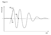
- FIG. 3 shows a purely exemplary temporal course of the received signal, which receives the evaluation unit 32 from the analog preprocessing path 34. Due to the vibration generated by the filter 42, the shape of the received signal is not simply a distorted repetition of the transmit pulse, but roughly forms a sine signal of decaying amplitude.
- the receive signal offers a variety of characteristics such as zeros, extremes or Turning points where the time of reception can be determined clearly. For example, the zero point 56 could be used for a small and moderate reception level.
- the evaluation unit 32 already knows from the reception level without concrete knowledge of this signal that a reflector is detected, it may be useful to change this criterion, for example in order to search for a characteristic of the reception signal that is level-independent.
- the receive level here in binary form as information about whether a reflector is touched, thus serves not only as a correction parameter, but as a switch between completely different procedure in the evaluation.
- the invention has been explained using the example of the power supply 38 as an additional circuit.
- the additional circuit can also contain other elements.
- an APD as a light receiver 26 is generally operated with a parallel capacitance which is grounded and provides the necessary energy for pulse responses.
- In the base point towards the mass can also be a current measurement in particular by means of shunt resistor.
- the current is determined, in particular by using a low-pass filter, the average current, the pulses during the light transit time measurement.
Claims (12)
- Détecteur optoélectronique (10) destiné à détecter des objets dans une zone à surveiller (20), qui comprend un émetteur de lumière (12) pour émettre un signal lumineux dans la zone à surveiller (20), un récepteur de lumière (26) pour transformer le signal lumineux (22) réfléchi ou réémis par un objet en un signal électrique de réception, un circuit supplémentaire (38) pour le fonctionnement du récepteur de lumière (26) et une unité d'évaluation (32) conçue pour déterminer un instant de réception du signal lumineux à l'aide du signal de réception et ainsi une distance de l'objet par un procédé de temps de parcours de la lumière, caractérisé en ce que l'unité d'évaluation (32) est conçue pour déterminer un niveau de réception du signal de réception à partir des informations de mesure dans le circuit supplémentaire (36,38) et pour effectuer une correction lors de la détermination de la distance à partir du niveau de réception ou bien pour choisir l'algorithme d'évaluation pour le procédé de temps de parcours de la lumière en fonction du niveau de réception.
- Détecteur (10) selon la revendication 1,
dans lequel le circuit supplémentaire (38) comprend une alimentation en tension du récepteur de lumière (26). - Détecteur (10) selon la revendication 1 ou 2,
dans lequel le circuit supplémentaire (38) comprend un condensateur pour mettre à disposition une charge pour des réponses impulsionnelles du récepteur de lumière (26). - Détecteur (10) selon l'une des revendications précédentes,
dans lequel l'unité d'évaluation (32, 52) est conçue pour comparer le niveau de réception à un niveau de réception attendu d'un réflecteur. - Détecteur (10) selon l'une des revendications précédentes,
dans lequel une unité de mesure de courant (48), en particulier pourvue d'une résistance shunt, est connectée au circuit supplémentaire (38). - Détecteur (10) selon l'une des revendications précédentes,
dans lequel l'unité d'évaluation (32) est conçue pour émettre une multitude d'impulsions de lumière et pour moyenner les signaux de réception qui en sont générés. - Détecteur (10) selon l'une des revendications précédentes,
dans lequel un filtre passe-bas (50) est connecté au circuit supplémentaire (38), à l'aide duquel les informations de mesure sont saisies de façon moyennée. - Détecteur (10) selon l'une des revendications précédentes,
dans lequel est prévu un circuit de test (54) qui injecte un signal de test artificiel dans le circuit supplémentaire (38), qui correspond à un niveau de réception élevé. - Détecteur (10) selon l'une des revendications précédentes,
qui est réalisé sous forme de scanneur laser pourvu d'une unité de déviation (18) au moyen de laquelle le rayon lumineux (16, 22) balaie périodiquement la zone à surveiller (20). - Procédé de détection d'objets dans une zone à surveiller (20), dans lequel un signal lumineux (16) est émis dans la zone à surveiller (20), un signal lumineux (22) réfléchi ou réémis par un objet est transformé en un signal électrique de réception dans un récepteur de lumière (26), le signal de réception étant évalué pour déterminer un instant de réception du signal lumineux et ainsi une distance de l'objet au moyen d'un procédé de temps de parcours de la lumière,
caractérisé en ce que
un niveau de réception du signal de réception est déterminé à partir des informations de mesure d'un circuit supplémentaire (36, 38) pour le fonctionnement du récepteur de lumière (26), et à partir du niveau de réception on effectue une correction lors de la détermination de la distance ou bien on choisit un algorithme d'évaluation pour le procédé de temps de parcours de la lumière en fonction du niveau de réception. - Procédé selon la revendication 10,
dans lequel on obtient les informations de mesure par une mesure du courant (48) au moyen d'une résistance shunt à partir du circuit supplémentaire (38). - Procédé selon la revendication 10 ou 11,
dans lequel on obtient les informations de mesure après un filtrage au filtre passe-bas (50).
Priority Applications (2)
| Application Number | Priority Date | Filing Date | Title |
|---|---|---|---|
| EP15155879.8A EP3059608B1 (fr) | 2015-02-20 | 2015-02-20 | Capteur optoélectronique et procédé destiné à la détection d'objets |
| US15/041,625 US20160245901A1 (en) | 2015-02-20 | 2016-02-11 | Optoelectronic sensor and method for the detection of objects |
Applications Claiming Priority (1)
| Application Number | Priority Date | Filing Date | Title |
|---|---|---|---|
| EP15155879.8A EP3059608B1 (fr) | 2015-02-20 | 2015-02-20 | Capteur optoélectronique et procédé destiné à la détection d'objets |
Publications (2)
| Publication Number | Publication Date |
|---|---|
| EP3059608A1 EP3059608A1 (fr) | 2016-08-24 |
| EP3059608B1 true EP3059608B1 (fr) | 2016-11-30 |
Family
ID=52807516
Family Applications (1)
| Application Number | Title | Priority Date | Filing Date |
|---|---|---|---|
| EP15155879.8A Active EP3059608B1 (fr) | 2015-02-20 | 2015-02-20 | Capteur optoélectronique et procédé destiné à la détection d'objets |
Country Status (2)
| Country | Link |
|---|---|
| US (1) | US20160245901A1 (fr) |
| EP (1) | EP3059608B1 (fr) |
Families Citing this family (5)
| Publication number | Priority date | Publication date | Assignee | Title |
|---|---|---|---|---|
| EP3663798B1 (fr) * | 2018-12-07 | 2021-01-27 | Sick Ag | Détecteur optoélectronique et procédé de détection et de détermination de distance des objets |
| EP4249948A1 (fr) | 2022-03-25 | 2023-09-27 | Sick Ag | Détection et détermination de la distance d'un objet |
| EP4249949B1 (fr) | 2022-03-25 | 2024-03-13 | Sick Ag | Détection et détermination de la distance d'un objet |
| EP4249950B1 (fr) | 2022-03-25 | 2024-03-13 | Sick Ag | Détection et détermination de la distance d'un objet |
| EP4254001B1 (fr) | 2022-04-01 | 2024-03-13 | Sick Ag | Détection d'objets dans une zone de surveillance |
Family Cites Families (14)
| Publication number | Priority date | Publication date | Assignee | Title |
|---|---|---|---|---|
| JPH11508359A (ja) * | 1995-06-22 | 1999-07-21 | 3ディブイ・システムズ・リミテッド | 改善された光学測距カメラ |
| DE10153270A1 (de) * | 2001-10-29 | 2003-05-08 | Sick Ag | Optoelektronische Entfernungsmesseinrichtung |
| US6919716B1 (en) * | 2002-08-28 | 2005-07-19 | Cisco Technology, Inc. | Precision avalanche photodiode current monitor |
| JP4379328B2 (ja) * | 2004-12-20 | 2009-12-09 | 住友電気工業株式会社 | 光受信器 |
| DE102007013714A1 (de) | 2007-03-22 | 2008-10-02 | Sick Ag | Optoelektronischer Sensor und Verfahren zur Messung einer Entfernung oder einer Entfernungsänderung |
| EP1990656A1 (fr) | 2007-05-07 | 2008-11-12 | Sick Ag | Atténuateur avec diodes PIN pour appareil de mesure de distances optique |
| JP2009134573A (ja) * | 2007-11-30 | 2009-06-18 | Nec Corp | マルチチップ半導体装置およびデータ転送方法 |
| US8311374B2 (en) * | 2008-07-29 | 2012-11-13 | University Of Washington | Beam generation and steering with integrated optical circuits for light detection and ranging |
| US8294881B2 (en) * | 2008-08-26 | 2012-10-23 | Honeywell International Inc. | Security system using LADAR-based sensors |
| EP2182377B1 (fr) | 2008-10-30 | 2012-09-19 | Sick Ag | Scanner laser mesurant l'éloignement |
| ATE483993T1 (de) * | 2008-11-21 | 2010-10-15 | Sick Ag | Optoelektronischer sensor und verfahren zur messung von entfernungen nach dem lichtlaufzeitprinzip |
| ES2348823T3 (es) * | 2008-11-21 | 2010-12-15 | Sick Ag | SENSOR OPTOELÉCTRONICO Y PROCEDIMIENTO PARA MEDIR DISTANCIAS SEGÚN EL PRINCIPIO DEL TIEMPO DE PROPAGACIÓN DE LA LUZ. |
| EP2189804B1 (fr) * | 2008-11-21 | 2010-10-06 | Sick Ag | Capteur optoélectronique et procédé destiné à la mesure de distance selon le principe du temps de propagation de la lumière |
| DE102010061382B4 (de) | 2010-12-21 | 2019-02-14 | Sick Ag | Optoelektronischer Sensor und Verfahren zur Erfassung und Abstandsbestimmung von Objekten |
-
2015
- 2015-02-20 EP EP15155879.8A patent/EP3059608B1/fr active Active
-
2016
- 2016-02-11 US US15/041,625 patent/US20160245901A1/en not_active Abandoned
Non-Patent Citations (1)
| Title |
|---|
| None * |
Also Published As
| Publication number | Publication date |
|---|---|
| EP3059608A1 (fr) | 2016-08-24 |
| US20160245901A1 (en) | 2016-08-25 |
Similar Documents
| Publication | Publication Date | Title |
|---|---|---|
| EP2899565B1 (fr) | Capteur mesurant l'éloignement et procédé destiné à la détection et la détermination de l'éloignement d'objets | |
| EP2541273B1 (fr) | Détection et détermination de distance d'objets | |
| EP2395368B1 (fr) | Scanner laser mesurant l'éloignement destiné à la détection d'objets dans une zone de surveillance | |
| EP3059608B1 (fr) | Capteur optoélectronique et procédé destiné à la détection d'objets | |
| EP2942644B1 (fr) | Capteur télémétrique et procédé destiné à la détection et la détermination de l'éloignement d'objets | |
| EP2824478B1 (fr) | Capteur optoélectronique et procédé destiné à la détection d'objets et à la détermination de distance dans une zone de surveillance | |
| EP2942645B1 (fr) | Capteur télémétrique et procédé destiné à la détection et la détermination de l'éloignement d'objets | |
| DE102013100696B3 (de) | Optoelektronischer Sensor und Verfahren zur Erfassung von Objekten in einem Überwachungsbereich | |
| EP2469296B1 (fr) | Capteur optoélectronique et procédé destiné à la détection et la détermination de l'éloignement d'objets | |
| EP1972961B1 (fr) | Capteur optoélectronique et procédé de mesure de l'éloignement ou de la modification de l'éloignement | |
| EP3557286B1 (fr) | Capteur optoélectronique et procédé de détection et de détermination de distance d'un objet | |
| EP3330741B1 (fr) | Capteur optoélectronique et procédé de détection d'objets dans une zone de détection | |
| EP2755048A1 (fr) | Capteur optoélectronique de mesure de distance et procédé de mesure de distance d'objets | |
| EP2735887A1 (fr) | Dispositif d'enregistrement optique | |
| EP3839556B1 (fr) | Capteur optoélectronique et procédé de détection d'un objet | |
| EP2910972B1 (fr) | Capteur mesurant l'éloignement et procédé destiné à la détermination de distance d'objets dans une zone de surveillance | |
| DE202019100793U1 (de) | Optoelektronischer Sensor zur Erfassung von Objekten | |
| EP4249950B1 (fr) | Détection et détermination de la distance d'un objet | |
| EP4249949B1 (fr) | Détection et détermination de la distance d'un objet | |
| EP3663798B1 (fr) | Détecteur optoélectronique et procédé de détection et de détermination de distance des objets | |
| EP3671264B1 (fr) | Capteur et procédé de détection d'un objet | |
| DE202014103348U1 (de) | Entfernungsmessender Sensor zur Erfassung und Abstandsbestimmung von Objekten | |
| EP4283331A1 (fr) | Détection optique et mesure de distance | |
| DE202013100327U1 (de) | Optoelektronischer Sensor zur Erfassung von Objekten in einem Überwachungsbereich | |
| EP4249948A1 (fr) | Détection et détermination de la distance d'un objet |
Legal Events
| Date | Code | Title | Description |
|---|---|---|---|
| PUAI | Public reference made under article 153(3) epc to a published international application that has entered the european phase |
Free format text: ORIGINAL CODE: 0009012 |
|
| 17P | Request for examination filed |
Effective date: 20150924 |
|
| AK | Designated contracting states |
Kind code of ref document: A1 Designated state(s): AL AT BE BG CH CY CZ DE DK EE ES FI FR GB GR HR HU IE IS IT LI LT LU LV MC MK MT NL NO PL PT RO RS SE SI SK SM TR |
|
| AX | Request for extension of the european patent |
Extension state: BA ME |
|
| GRAP | Despatch of communication of intention to grant a patent |
Free format text: ORIGINAL CODE: EPIDOSNIGR1 |
|
| INTG | Intention to grant announced |
Effective date: 20160914 |
|
| GRAS | Grant fee paid |
Free format text: ORIGINAL CODE: EPIDOSNIGR3 |
|
| GRAA | (expected) grant |
Free format text: ORIGINAL CODE: 0009210 |
|
| AK | Designated contracting states |
Kind code of ref document: B1 Designated state(s): AL AT BE BG CH CY CZ DE DK EE ES FI FR GB GR HR HU IE IS IT LI LT LU LV MC MK MT NL NO PL PT RO RS SE SI SK SM TR |
|
| REG | Reference to a national code |
Ref country code: CH Ref legal event code: EP Ref country code: GB Ref legal event code: FG4D Free format text: NOT ENGLISH |
|
| REG | Reference to a national code |
Ref country code: AT Ref legal event code: REF Ref document number: 850315 Country of ref document: AT Kind code of ref document: T Effective date: 20161215 |
|
| REG | Reference to a national code |
Ref country code: IE Ref legal event code: FG4D Free format text: LANGUAGE OF EP DOCUMENT: GERMAN |
|
| REG | Reference to a national code |
Ref country code: DE Ref legal event code: R096 Ref document number: 502015000339 Country of ref document: DE |
|
| REG | Reference to a national code |
Ref country code: FR Ref legal event code: PLFP Year of fee payment: 3 |
|
| PG25 | Lapsed in a contracting state [announced via postgrant information from national office to epo] |
Ref country code: LV Free format text: LAPSE BECAUSE OF FAILURE TO SUBMIT A TRANSLATION OF THE DESCRIPTION OR TO PAY THE FEE WITHIN THE PRESCRIBED TIME-LIMIT Effective date: 20161130 |
|
| REG | Reference to a national code |
Ref country code: LT Ref legal event code: MG4D |
|
| REG | Reference to a national code |
Ref country code: NL Ref legal event code: MP Effective date: 20161130 |
|
| PG25 | Lapsed in a contracting state [announced via postgrant information from national office to epo] |
Ref country code: SE Free format text: LAPSE BECAUSE OF FAILURE TO SUBMIT A TRANSLATION OF THE DESCRIPTION OR TO PAY THE FEE WITHIN THE PRESCRIBED TIME-LIMIT Effective date: 20161130 Ref country code: LT Free format text: LAPSE BECAUSE OF FAILURE TO SUBMIT A TRANSLATION OF THE DESCRIPTION OR TO PAY THE FEE WITHIN THE PRESCRIBED TIME-LIMIT Effective date: 20161130 Ref country code: GR Free format text: LAPSE BECAUSE OF FAILURE TO SUBMIT A TRANSLATION OF THE DESCRIPTION OR TO PAY THE FEE WITHIN THE PRESCRIBED TIME-LIMIT Effective date: 20170301 Ref country code: NO Free format text: LAPSE BECAUSE OF FAILURE TO SUBMIT A TRANSLATION OF THE DESCRIPTION OR TO PAY THE FEE WITHIN THE PRESCRIBED TIME-LIMIT Effective date: 20170228 |
|
| PG25 | Lapsed in a contracting state [announced via postgrant information from national office to epo] |
Ref country code: FI Free format text: LAPSE BECAUSE OF FAILURE TO SUBMIT A TRANSLATION OF THE DESCRIPTION OR TO PAY THE FEE WITHIN THE PRESCRIBED TIME-LIMIT Effective date: 20161130 Ref country code: PL Free format text: LAPSE BECAUSE OF FAILURE TO SUBMIT A TRANSLATION OF THE DESCRIPTION OR TO PAY THE FEE WITHIN THE PRESCRIBED TIME-LIMIT Effective date: 20161130 Ref country code: BE Free format text: LAPSE BECAUSE OF NON-PAYMENT OF DUE FEES Effective date: 20170228 Ref country code: PT Free format text: LAPSE BECAUSE OF FAILURE TO SUBMIT A TRANSLATION OF THE DESCRIPTION OR TO PAY THE FEE WITHIN THE PRESCRIBED TIME-LIMIT Effective date: 20170330 Ref country code: ES Free format text: LAPSE BECAUSE OF FAILURE TO SUBMIT A TRANSLATION OF THE DESCRIPTION OR TO PAY THE FEE WITHIN THE PRESCRIBED TIME-LIMIT Effective date: 20161130 Ref country code: RS Free format text: LAPSE BECAUSE OF FAILURE TO SUBMIT A TRANSLATION OF THE DESCRIPTION OR TO PAY THE FEE WITHIN THE PRESCRIBED TIME-LIMIT Effective date: 20161130 Ref country code: HR Free format text: LAPSE BECAUSE OF FAILURE TO SUBMIT A TRANSLATION OF THE DESCRIPTION OR TO PAY THE FEE WITHIN THE PRESCRIBED TIME-LIMIT Effective date: 20161130 |
|
| PG25 | Lapsed in a contracting state [announced via postgrant information from national office to epo] |
Ref country code: NL Free format text: LAPSE BECAUSE OF FAILURE TO SUBMIT A TRANSLATION OF THE DESCRIPTION OR TO PAY THE FEE WITHIN THE PRESCRIBED TIME-LIMIT Effective date: 20161130 |
|
| PG25 | Lapsed in a contracting state [announced via postgrant information from national office to epo] |
Ref country code: CZ Free format text: LAPSE BECAUSE OF FAILURE TO SUBMIT A TRANSLATION OF THE DESCRIPTION OR TO PAY THE FEE WITHIN THE PRESCRIBED TIME-LIMIT Effective date: 20161130 Ref country code: SK Free format text: LAPSE BECAUSE OF FAILURE TO SUBMIT A TRANSLATION OF THE DESCRIPTION OR TO PAY THE FEE WITHIN THE PRESCRIBED TIME-LIMIT Effective date: 20161130 Ref country code: DK Free format text: LAPSE BECAUSE OF FAILURE TO SUBMIT A TRANSLATION OF THE DESCRIPTION OR TO PAY THE FEE WITHIN THE PRESCRIBED TIME-LIMIT Effective date: 20161130 Ref country code: EE Free format text: LAPSE BECAUSE OF FAILURE TO SUBMIT A TRANSLATION OF THE DESCRIPTION OR TO PAY THE FEE WITHIN THE PRESCRIBED TIME-LIMIT Effective date: 20161130 Ref country code: RO Free format text: LAPSE BECAUSE OF FAILURE TO SUBMIT A TRANSLATION OF THE DESCRIPTION OR TO PAY THE FEE WITHIN THE PRESCRIBED TIME-LIMIT Effective date: 20161130 |
|
| PG25 | Lapsed in a contracting state [announced via postgrant information from national office to epo] |
Ref country code: SM Free format text: LAPSE BECAUSE OF FAILURE TO SUBMIT A TRANSLATION OF THE DESCRIPTION OR TO PAY THE FEE WITHIN THE PRESCRIBED TIME-LIMIT Effective date: 20161130 Ref country code: IT Free format text: LAPSE BECAUSE OF FAILURE TO SUBMIT A TRANSLATION OF THE DESCRIPTION OR TO PAY THE FEE WITHIN THE PRESCRIBED TIME-LIMIT Effective date: 20161130 Ref country code: BG Free format text: LAPSE BECAUSE OF FAILURE TO SUBMIT A TRANSLATION OF THE DESCRIPTION OR TO PAY THE FEE WITHIN THE PRESCRIBED TIME-LIMIT Effective date: 20170228 |
|
| REG | Reference to a national code |
Ref country code: DE Ref legal event code: R097 Ref document number: 502015000339 Country of ref document: DE |
|
| PG25 | Lapsed in a contracting state [announced via postgrant information from national office to epo] |
Ref country code: MC Free format text: LAPSE BECAUSE OF FAILURE TO SUBMIT A TRANSLATION OF THE DESCRIPTION OR TO PAY THE FEE WITHIN THE PRESCRIBED TIME-LIMIT Effective date: 20161130 |
|
| PLBE | No opposition filed within time limit |
Free format text: ORIGINAL CODE: 0009261 |
|
| STAA | Information on the status of an ep patent application or granted ep patent |
Free format text: STATUS: NO OPPOSITION FILED WITHIN TIME LIMIT |
|
| 26N | No opposition filed |
Effective date: 20170831 |
|
| REG | Reference to a national code |
Ref country code: IE Ref legal event code: MM4A |
|
| PG25 | Lapsed in a contracting state [announced via postgrant information from national office to epo] |
Ref country code: SI Free format text: LAPSE BECAUSE OF FAILURE TO SUBMIT A TRANSLATION OF THE DESCRIPTION OR TO PAY THE FEE WITHIN THE PRESCRIBED TIME-LIMIT Effective date: 20161130 |
|
| PG25 | Lapsed in a contracting state [announced via postgrant information from national office to epo] |
Ref country code: LU Free format text: LAPSE BECAUSE OF NON-PAYMENT OF DUE FEES Effective date: 20170220 |
|
| REG | Reference to a national code |
Ref country code: BE Ref legal event code: MM Effective date: 20170228 |
|
| REG | Reference to a national code |
Ref country code: FR Ref legal event code: PLFP Year of fee payment: 4 |
|
| PG25 | Lapsed in a contracting state [announced via postgrant information from national office to epo] |
Ref country code: IE Free format text: LAPSE BECAUSE OF NON-PAYMENT OF DUE FEES Effective date: 20170220 |
|
| PG25 | Lapsed in a contracting state [announced via postgrant information from national office to epo] |
Ref country code: MT Free format text: LAPSE BECAUSE OF FAILURE TO SUBMIT A TRANSLATION OF THE DESCRIPTION OR TO PAY THE FEE WITHIN THE PRESCRIBED TIME-LIMIT Effective date: 20161130 |
|
| PGFP | Annual fee paid to national office [announced via postgrant information from national office to epo] |
Ref country code: CH Payment date: 20190221 Year of fee payment: 5 |
|
| PG25 | Lapsed in a contracting state [announced via postgrant information from national office to epo] |
Ref country code: HU Free format text: LAPSE BECAUSE OF FAILURE TO SUBMIT A TRANSLATION OF THE DESCRIPTION OR TO PAY THE FEE WITHIN THE PRESCRIBED TIME-LIMIT; INVALID AB INITIO Effective date: 20150220 |
|
| PG25 | Lapsed in a contracting state [announced via postgrant information from national office to epo] |
Ref country code: CY Free format text: LAPSE BECAUSE OF FAILURE TO SUBMIT A TRANSLATION OF THE DESCRIPTION OR TO PAY THE FEE WITHIN THE PRESCRIBED TIME-LIMIT Effective date: 20161130 |
|
| PG25 | Lapsed in a contracting state [announced via postgrant information from national office to epo] |
Ref country code: MK Free format text: LAPSE BECAUSE OF FAILURE TO SUBMIT A TRANSLATION OF THE DESCRIPTION OR TO PAY THE FEE WITHIN THE PRESCRIBED TIME-LIMIT Effective date: 20161130 |
|
| PG25 | Lapsed in a contracting state [announced via postgrant information from national office to epo] |
Ref country code: TR Free format text: LAPSE BECAUSE OF FAILURE TO SUBMIT A TRANSLATION OF THE DESCRIPTION OR TO PAY THE FEE WITHIN THE PRESCRIBED TIME-LIMIT Effective date: 20161130 |
|
| PG25 | Lapsed in a contracting state [announced via postgrant information from national office to epo] |
Ref country code: AL Free format text: LAPSE BECAUSE OF FAILURE TO SUBMIT A TRANSLATION OF THE DESCRIPTION OR TO PAY THE FEE WITHIN THE PRESCRIBED TIME-LIMIT Effective date: 20161130 Ref country code: IS Free format text: LAPSE BECAUSE OF FAILURE TO SUBMIT A TRANSLATION OF THE DESCRIPTION OR TO PAY THE FEE WITHIN THE PRESCRIBED TIME-LIMIT Effective date: 20170330 |
|
| REG | Reference to a national code |
Ref country code: CH Ref legal event code: PL |
|
| PG25 | Lapsed in a contracting state [announced via postgrant information from national office to epo] |
Ref country code: CH Free format text: LAPSE BECAUSE OF NON-PAYMENT OF DUE FEES Effective date: 20200229 Ref country code: LI Free format text: LAPSE BECAUSE OF NON-PAYMENT OF DUE FEES Effective date: 20200229 |
|
| REG | Reference to a national code |
Ref country code: AT Ref legal event code: MM01 Ref document number: 850315 Country of ref document: AT Kind code of ref document: T Effective date: 20200220 |
|
| PG25 | Lapsed in a contracting state [announced via postgrant information from national office to epo] |
Ref country code: AT Free format text: LAPSE BECAUSE OF NON-PAYMENT OF DUE FEES Effective date: 20200220 |
|
| PGFP | Annual fee paid to national office [announced via postgrant information from national office to epo] |
Ref country code: FR Payment date: 20230217 Year of fee payment: 9 |
|
| PGFP | Annual fee paid to national office [announced via postgrant information from national office to epo] |
Ref country code: GB Payment date: 20230221 Year of fee payment: 9 Ref country code: DE Payment date: 20230216 Year of fee payment: 9 |
|
| PGFP | Annual fee paid to national office [announced via postgrant information from national office to epo] |
Ref country code: DE Payment date: 20240216 Year of fee payment: 10 Ref country code: GB Payment date: 20240222 Year of fee payment: 10 |