EP2910972B1 - Capteur mesurant l'éloignement et procédé destiné à la détermination de distance d'objets dans une zone de surveillance - Google Patents
Capteur mesurant l'éloignement et procédé destiné à la détermination de distance d'objets dans une zone de surveillance Download PDFInfo
- Publication number
- EP2910972B1 EP2910972B1 EP15151418.9A EP15151418A EP2910972B1 EP 2910972 B1 EP2910972 B1 EP 2910972B1 EP 15151418 A EP15151418 A EP 15151418A EP 2910972 B1 EP2910972 B1 EP 2910972B1
- Authority
- EP
- European Patent Office
- Prior art keywords
- signal
- sensor
- voltage
- unit
- distance
- Prior art date
- Legal status (The legal status is an assumption and is not a legal conclusion. Google has not performed a legal analysis and makes no representation as to the accuracy of the status listed.)
- Active
Links
- 238000000034 method Methods 0.000 title claims description 23
- 238000012544 monitoring process Methods 0.000 title claims description 9
- 238000011156 evaluation Methods 0.000 claims description 22
- 230000005540 biological transmission Effects 0.000 claims description 14
- 239000003990 capacitor Substances 0.000 claims description 9
- 230000005693 optoelectronics Effects 0.000 claims description 5
- 230000035945 sensitivity Effects 0.000 claims description 2
- 238000005259 measurement Methods 0.000 description 23
- 238000001514 detection method Methods 0.000 description 15
- 230000003287 optical effect Effects 0.000 description 7
- 238000010586 diagram Methods 0.000 description 6
- 230000008901 benefit Effects 0.000 description 5
- 230000000295 complement effect Effects 0.000 description 4
- 238000001914 filtration Methods 0.000 description 4
- 230000003321 amplification Effects 0.000 description 3
- 230000015556 catabolic process Effects 0.000 description 3
- 238000003199 nucleic acid amplification method Methods 0.000 description 3
- 230000008569 process Effects 0.000 description 3
- 238000002592 echocardiography Methods 0.000 description 2
- 238000012545 processing Methods 0.000 description 2
- 230000000630 rising effect Effects 0.000 description 2
- 238000002604 ultrasonography Methods 0.000 description 2
- 238000012935 Averaging Methods 0.000 description 1
- 238000013459 approach Methods 0.000 description 1
- 230000004888 barrier function Effects 0.000 description 1
- 239000000872 buffer Substances 0.000 description 1
- 230000008859 change Effects 0.000 description 1
- 238000006243 chemical reaction Methods 0.000 description 1
- 230000008878 coupling Effects 0.000 description 1
- 238000010168 coupling process Methods 0.000 description 1
- 238000005859 coupling reaction Methods 0.000 description 1
- 238000005516 engineering process Methods 0.000 description 1
- 238000005192 partition Methods 0.000 description 1
- 230000010363 phase shift Effects 0.000 description 1
- 230000036278 prepulse Effects 0.000 description 1
- 230000035484 reaction time Effects 0.000 description 1
- 238000001228 spectrum Methods 0.000 description 1
- 230000003068 static effect Effects 0.000 description 1
Images


Classifications
-
- G—PHYSICS
- G01—MEASURING; TESTING
- G01S—RADIO DIRECTION-FINDING; RADIO NAVIGATION; DETERMINING DISTANCE OR VELOCITY BY USE OF RADIO WAVES; LOCATING OR PRESENCE-DETECTING BY USE OF THE REFLECTION OR RERADIATION OF RADIO WAVES; ANALOGOUS ARRANGEMENTS USING OTHER WAVES
- G01S17/00—Systems using the reflection or reradiation of electromagnetic waves other than radio waves, e.g. lidar systems
- G01S17/02—Systems using the reflection of electromagnetic waves other than radio waves
- G01S17/06—Systems determining position data of a target
- G01S17/08—Systems determining position data of a target for measuring distance only
- G01S17/10—Systems determining position data of a target for measuring distance only using transmission of interrupted, pulse-modulated waves
-
- G—PHYSICS
- G01—MEASURING; TESTING
- G01S—RADIO DIRECTION-FINDING; RADIO NAVIGATION; DETERMINING DISTANCE OR VELOCITY BY USE OF RADIO WAVES; LOCATING OR PRESENCE-DETECTING BY USE OF THE REFLECTION OR RERADIATION OF RADIO WAVES; ANALOGOUS ARRANGEMENTS USING OTHER WAVES
- G01S7/00—Details of systems according to groups G01S13/00, G01S15/00, G01S17/00
- G01S7/48—Details of systems according to groups G01S13/00, G01S15/00, G01S17/00 of systems according to group G01S17/00
- G01S7/483—Details of pulse systems
- G01S7/486—Receivers
- G01S7/4861—Circuits for detection, sampling, integration or read-out
-
- G—PHYSICS
- G01—MEASURING; TESTING
- G01S—RADIO DIRECTION-FINDING; RADIO NAVIGATION; DETERMINING DISTANCE OR VELOCITY BY USE OF RADIO WAVES; LOCATING OR PRESENCE-DETECTING BY USE OF THE REFLECTION OR RERADIATION OF RADIO WAVES; ANALOGOUS ARRANGEMENTS USING OTHER WAVES
- G01S7/00—Details of systems according to groups G01S13/00, G01S15/00, G01S17/00
- G01S7/48—Details of systems according to groups G01S13/00, G01S15/00, G01S17/00 of systems according to group G01S17/00
- G01S7/483—Details of pulse systems
- G01S7/486—Receivers
- G01S7/4865—Time delay measurement, e.g. time-of-flight measurement, time of arrival measurement or determining the exact position of a peak
-
- G—PHYSICS
- G01—MEASURING; TESTING
- G01S—RADIO DIRECTION-FINDING; RADIO NAVIGATION; DETERMINING DISTANCE OR VELOCITY BY USE OF RADIO WAVES; LOCATING OR PRESENCE-DETECTING BY USE OF THE REFLECTION OR RERADIATION OF RADIO WAVES; ANALOGOUS ARRANGEMENTS USING OTHER WAVES
- G01S7/00—Details of systems according to groups G01S13/00, G01S15/00, G01S17/00
- G01S7/48—Details of systems according to groups G01S13/00, G01S15/00, G01S17/00 of systems according to group G01S17/00
- G01S7/497—Means for monitoring or calibrating
Definitions
- the invention relates to a distance-measuring sensor and a method for detecting and determining the distance of objects in a monitoring area according to the preamble of claims 1 and 10, respectively.
- Numerous sensors use a signal transit time principle in which the time interval between transmission and reception of a signal is converted into a distance over the signal propagation time. In this way, different frequency ranges of the electromagnetic spectrum such as microwaves and light and also other physical signals such as ultrasound are utilized.
- optoelectronic sensors according to the principle of the light transit time method light signals are emitted, and the time until reception of the light signals reflected or reflected on objects is measured. Due to the constant propagation speed of the signal, the signal transit time can be converted directly into a distance.
- Optoelectronic distance measurement can be required for example in vehicle safety, logistics or factory automation or safety technology. In most cases, the desired output size is the measured distance.
- a rangefinder according to the light transit time method can also operate switching by detecting a change in distance of a reflector expected at a specific distance or of a reflecting or remitting object.
- a special application is a reflection light barrier with monitoring of the distance to its reflector.
- the light transit time method is also the principle by which distance-measuring laser scanners operate, periodically scanning a surveillance plane or even a three-dimensional space area. If several distance detectors are combined next to each other, a time-of-flight camera is created takes three-dimensional image data. In this case, integrated image sensors can be formed, which make the distance measurement in their pixels.
- Precondition for an accurate signal propagation time measurement is the precise determination of the reception time.
- various methods are known.
- a phase method a periodically modulated signal is transmitted and the phase shift between transmitted and received signals is determined.
- a pulse method uses a signal that allows accurate timing. The detection takes place in the simplest case by comparator thresholds, in more complex processes, the entire received signal is sampled and evaluated digitally to locate the received pulse.
- a pulse averaging method transmits a plurality of transmit pulses and statistically evaluates the subsequently received pulses.
- the light signal is first converted into an electrical signal and amplified in an analog electronic circuit. Since a photodetector generates a photocurrent, a transimpedance amplifier is used as the first amplifier stage, so that subsequently voltage signals are available.
- the signal echo to be detected can come from objects with very different reflective or scattering properties and brightness, and also from short distances of a few centimeters or distances of many meters or even kilometers.
- the signal transit time method is very universal and can deal with this variety in itself.
- the different measurement conditions result in a very large dynamic range, which can for example be up to 120 dB and more for laser scanners.
- sensitive optical detectors such as PIN diodes or avalanche diodes (APDs) are capable of detecting even the smallest of optical signals, dynamic range is a major challenge for electronics.
- the EP 2 182 379 A1 here goes one step further and uses information from the measuring pulse itself to adjust the gain by the received signal for the actual evaluation is slowed down by a delay line, so that the gain can be adjusted in time.
- each of the amplifier in view of the shortness of the light pulses and the repeated measurements quickly and without delay adjust.
- the dynamic range is split into multiple paths with complementary gain ranges. From the above numbers of 30-40 dB per channel and a desired dynamic range of 120 dB results that at least three channels are required for this. Even more serious, however, is that the individual channels influence each other. The consequences are increased noise, increased susceptibility to interference and a reduced detection capability.
- the US 5,359,404 discloses a laser-based velocity measuring device that can perform range finding according to a pulse transit time method.
- a high voltage power supply provides the power to emit the laser pulses and biases the light receiver.
- the invention is based on the basic concept of developing additional measurement information independently of the actual received signal.
- a voltage dip of a bias unit of the receiver is measured and this signal for a light transit time measurement used.
- the reception time is therefore not or at least not exclusively determined from the actual received signal, but closed indirectly from the voltage dip on the reception time of the reflected signal on the receiver.
- the reception time need not be explicitly determined, since only the relative time interval is interested in a transmission time.
- the received signal is not affected by this evaluation of the voltage dip of the bias unit and is available without restriction for any further analog and digital evaluation steps.
- the invention has the advantage that, in addition to the amplified received signal itself, additional measurement information becomes available for the received signal. This can be used to extend the dynamic range.
- the evaluation unit is preferably designed to determine the light transit time in multiple channels on the basis of the received signal and the voltage dip signal.
- the received signal and the voltage dip signal are thus understood as two measuring channels. This can be used for a redundant or diversified measurement, or the results of the two measurement channels are compared or billed.
- the measuring channels are used to process different signal strengths in each case, so that the overall result is a significantly expanded dynamic range within which the time of reception and the amplitude of the remitted signal can be determined precisely and at least largely without amplification artifacts.
- a first amplifier is preferably provided in order to generate an amplified voltage signal from the received signal.
- this involves a transimpedance amplifier in order to generate the further voltage signal to be evaluated from a photocurrent of the receiver.
- the first amplifier is more preferably very sensitive to detect weak remitted signals. In this case, the strong remitted signals are complementarily detected via the voltage dip signal.
- the voltage measuring unit preferably has a second amplifier.
- the voltage drop signal in an adjustable specific portion of the dynamic range to be covered at least largely linearly detected.
- the first amplifier and the second amplifier preferably have matched gain factors so that the received signal and the voltage dip signal are detected in different sensitivity ranges.
- the voltage drop signal is weak or not amplified, so that the realized via the voltage drop of the bias unit additional measuring channel is responsible for the detection of strong remittierter signals.
- the actual received signal is amplified with a high amplification factor so that this measuring channel can process weakly remitted signals.
- This division has the advantage that because of the different detection principles, the strong signals detected by the voltage dip do not affect the evaluation of the weak signals.
- other settings of the amplification factors and thus other partitions of the measurement channels are also conceivable, including a little or even largely overlapping regions for a redundant data acquisition.
- the receiver is preferably an avalanche photodiode and the bias unit generates a high voltage.
- the avalanche photodiode is particularly suitable for optical detection over a wide dynamic range up to very weak signals. For this purpose, a high-voltage supply for biasing with a few hundred volts or more is needed, the break-in can be reliably detected upon detection of a signal as a voltage dip signal.
- the biasing unit preferably has a charging capacitor. Thereby, the voltage and also the high voltage of the bias unit after a detection, such as avalanche breakdown of an avalanche photodiode, restored.
- the biasing unit preferably has a resistance between the charging capacitor and ground, wherein the voltage measuring unit detects the voltage drop-in signal at the resistor.
- the tapped voltage drop signal is proportional to the current of the receiver, the waveforms of voltage dip signal and received signal thus correspond to each other without further filtering measures.
- the biasing unit preferably has a high-pass filter. This serves to filter out low-frequency components of the voltage breakdown signal, for example the comparatively slow charging of the charging capacitor.
- a suitable cutoff frequency which is adapted to the signal shape of the transmission signal results Then for the voltage drop signal a signal waveform comparable to the received signal, which simplifies the common or complementary evaluation in the two measurement channels.
- inventive method can be configured in a similar manner by further features and shows similar advantages. Such further features are exemplary, but not exhaustive, in which subclaims following the independent claims are described.
- FIG. 12 shows a block diagram of a distance-measuring sensor 10 in one embodiment as a one-dimensional opto-electronic distance sensor.
- a light transmitter 12 sends a light signal 16 via a transmission optical system 14 into a monitoring area 18.
- the light signal 16 when an object 20 is in the beam path, is reflected or remitted at this object 20 and returns to the sensor 10 as a remitted light signal 22.
- There it is guided by a receiving optical system 24 to a light receiver 26.
- the optical arrangement is to be understood purely by way of example, the invention also includes other arrangements, for example with divider mirrors or a light emitter in the cone of the light receiver.
- the explanation of a one-dimensional optoelectronic sensor is to be understood only as an example, as well as the sensor can be a multi-dimensional system, such as a laser scanner or a light runtime camera, or work with entirely different signals such as microwaves or ultrasound.
- the light receiver 26 is, for example, a PIN diode or an avalanche photodiode and biased by means of a biasing unit 28. If a remitted light signal 22 hits the photosensitive surface of the light receiver 26, a corresponding photocurrent is generated.
- the photocurrent is converted, for example with suitable transimpedance conversion in a voltage signal and fed to an evaluation unit 30, which is preferably at the same time responsible for the control tasks of the sensor 10. This can be an analog circuit, but usually the received signal is still digitized and the evaluation unit 30 is implemented on a digital evaluation module, such as a microprocessor or an FPGA (Field Programmable Gate Array).
- a short pulse generally at least one signal with a clearly identifiable time reference is transmitted. Accordingly, the echoes of objects 20 or interferers in the surveillance area 18 also have this waveform.
- the evaluation unit 30 determines the reception time from the reception signal by a threshold value method, by a search in the digitally present reception signal on the basis of the known transmission signal form or another method. It is also conceivable to emit a plurality of transmit pulses, which then collect received receive pulses and thus to determine a reception time by statistical means.
- the result of the evaluation is in each case the delay of the received signal relative to the transmission signal, that is to say the signal propagation time. With the help of the known propagation speed, in this case the speed of light, in other cases, for example, the speed of sound, the signal propagation time can be converted directly into a distance of the object 20.
- the transmit pulses are very short, or alternatively at least transmit signals with steep edges are used for the precise detection of a receive time, the photocurrent must be processed by an amplifier with sufficient bandwidth so as not to falsify the waveform.
- an amplitude range in the order of magnitude of 120 dB should also be detectable even with the least possible noise.
- the invention therefore has a circuit which utilizes the onset of photodiode high voltage, generally a voltage dip on the bias unit 28, for detection.
- a tension measuring unit 32 with the biasing unit 28 connected, which measures a voltage drop signal and passes to the evaluation unit 30.
- the voltage drop signal carries in principle the same information as the received signal, so that the evaluation unit 30 can perform the same evaluations thereon, in particular a distance measurement, but also a level determination and the like.
- the voltage dip signal and the received signal form the basis for two mutually complementary complementary receiving or measuring channels, so that overall a larger dynamic range is covered.
- the distance measurement takes place solely on the basis of the voltage breakdown signal. This can be useful, for example, if the received signal is needed for a completely different measurement and is therefore not available for a distance measurement.
- the measuring channels formed by the received signal or the voltage dip signal once more multi-channel, for example, to divide the total dynamic range to be covered in more than two sub-areas, or to provide an automatic gain control in these measurement channels.
- FIG. 2 shows a circuit diagram of an embodiment of the analog signal detection of the sensor 10.
- the photocurrent of the light receiver 26 is passed via a transimpedance amplifier 34 and possible further, not shown, amplifier stages as a received signal to the evaluation unit 30.
- the light receiver 26 is biased by means of the bias unit 28 and a charge capacitor 36 provided therein.
- the generation of the photocurrent leads to a collapse of the voltage in the biasing unit 28.
- This is detected by the voltage measuring unit 32 as a voltage drop signal and supplied accordingly as additional or alternative measurement information of the evaluation unit 30.
- a high-pass filter 38 is connected to suppress the low-frequency components of the voltage dip signal.
- the voltage drop signal can also be amplified by amplifier stages, not shown.
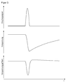
- FIG. 3 shows three purely exemplary signals of the analog signal detection according to FIG. 2 namely, from top to bottom, the photocurrent of the light receiver 26 as the actual received signal, the raw voltage drop signal to the charging capacitor 36 before filtering in the high-pass filter 38 and the voltage drop-in signal detected by the voltage measuring unit 32 after the filtering.
- FIG. 4 shows a circuit diagram of another embodiment of the analog signal detection of the sensor 10.
- the tap of the voltage dip signal is realized without additional AC coupling.
- an additional resistor 40 is connected between the charge capacitor 36 and ground, with the voltage measurement unit 32 measuring the voltage dip signal on this resistor 40. Since the voltage here is proportional to the photocurrent, the signal shape directly corresponds to that of the received signal of the light receiver 26.
- the desired gain of the voltage dip signal can be adjusted in this embodiment by a suitable choice of the resistor 40. Namely, the gain depends on the ratio of the resistor 40 to the resistance between the anode side of the light receiver 26 and ground.
- Another advantage of this embodiment is the direct measurement of the voltage measuring unit 30 to ground.
Landscapes
- Engineering & Computer Science (AREA)
- Physics & Mathematics (AREA)
- Computer Networks & Wireless Communication (AREA)
- General Physics & Mathematics (AREA)
- Radar, Positioning & Navigation (AREA)
- Remote Sensing (AREA)
- Electromagnetism (AREA)
- Optical Radar Systems And Details Thereof (AREA)
- Measurement Of Optical Distance (AREA)
Claims (10)
- Capteur destiné à la mesure d'éloignement (10), en particulier capteur optoélectronique, pour la détection et la détermination de distances d'objets (20) dans une zone de surveillance (18), ledit capteur (10) comprenant un émetteur (12) pour émettre un signal émis (16), un récepteur (26) pour engendrer un signal de réception à partir du signal émis (22) réémis dans la zone de surveillance (18), ainsi qu'une unité d'évaluation (30) qui est réalisée pour déterminer un temps de parcours du signal depuis le capteur (10) jusqu'à l'objet (20), dans lequel le récepteur (26) comprend une unité de mise sous tension (28), caractérisé en ce que
une unité de mesure de tension (32) est connectée avec l'unité de mise sous tension (28), afin d'engendrer un signal de chute de tension lors de la réception d'un signal émis réémis (22), et en ce que l'unité d'évaluation (30) est réalisée pour déterminer le temps de parcours du signal au moyen du signal de chute de tension. - Capteur (10) selon la revendication 1,
dans lequel l'unité d'évaluation (30) est réalisée pour déterminer le temps de parcours de la lumière sur plusieurs canaux au moyen du signal de réception et du signal de chute de tension. - Capteur (10) selon la revendication 1 ou 2,
dans lequel il est prévu un premier amplificateur (34) entre le récepteur (26) et l'unité d'évaluation (30), afin d'engendrer un signal de tension amplifié à partir du signal de réception. - Capteur (10) selon l'une des revendications précédentes,
dans lequel l'unité de mesure de tension (32) comprend un second amplificateur. - Capteur (10) selon la revendication 3 et 4,
dans lequel le premier amplificateur (34) et le second amplificateur présentent des facteurs d'amplification accordés l'un à l'autre, afin que le signal de réception et le signal de chute de tension soient détectés dans des plages de sensibilité différentes. - Capteur (10) selon l'une des revendications précédentes,
dans lequel le récepteur (26) est une photodiode à avalanche et l'unité de mise sous tension (28) engendre une haute tension. - Capteur (10) selon l'une des revendications précédentes,
dans lequel l'unité de mise sous tension (28) comprend un condensateur de charge (36). - Capteur (10) selon la revendication 7,
dans lequel l'unité de mise sous tension (28) comprend une résistance (40) entre le condensateur de charge (36) et la masse, et dans lequel l'unité de mesure de tension (32) détecte le signal de chute de tension au niveau de la résistance (40). - Capteur (10) selon l'une des revendications précédentes,
dans lequel l'unité de mise sous tension (28) comprend un filtre passe-haut (38). - Procédé pour la détection et la détermination de distances d'objets (20) dans une zone de surveillance (18), dans lequel on émet un signal émis (16), on reçoit un nouveau le signal émis réémis (22) hors de la zone de surveillance (18), et on détermine le temps de parcours du signal jusqu'à l'objet (20), dans lequel le signal émis réémis (22) est détecté par un récepteur (26) mis sous tension avec l'aide d'une unité de mise sous tension (28),
caractérisé en ce qu'on engendre au niveau de l'unité de mise sous tension (28), lors de la réception du signal émis réémis (22), un signal de chute de tension, et en ce que le temps de parcours du signal est déterminé au moyen du signal de chute de tension.
Applications Claiming Priority (1)
| Application Number | Priority Date | Filing Date | Title |
|---|---|---|---|
| DE102014102209.2A DE102014102209A1 (de) | 2014-02-20 | 2014-02-20 | Entfernungsmessender Sensor und Verfahren zur Abstandsbestimmung von Objekten in einem Ueberwachungsbereich |
Publications (2)
| Publication Number | Publication Date |
|---|---|
| EP2910972A1 EP2910972A1 (fr) | 2015-08-26 |
| EP2910972B1 true EP2910972B1 (fr) | 2016-05-25 |
Family
ID=52345118
Family Applications (1)
| Application Number | Title | Priority Date | Filing Date |
|---|---|---|---|
| EP15151418.9A Active EP2910972B1 (fr) | 2014-02-20 | 2015-01-16 | Capteur mesurant l'éloignement et procédé destiné à la détermination de distance d'objets dans une zone de surveillance |
Country Status (3)
| Country | Link |
|---|---|
| EP (1) | EP2910972B1 (fr) |
| JP (1) | JP2015155901A (fr) |
| DE (1) | DE102014102209A1 (fr) |
Families Citing this family (1)
| Publication number | Priority date | Publication date | Assignee | Title |
|---|---|---|---|---|
| EP3091271B1 (fr) | 2015-05-05 | 2018-07-11 | Sick Ag | Détecteur optique |
Family Cites Families (13)
| Publication number | Priority date | Publication date | Assignee | Title |
|---|---|---|---|---|
| US4464048A (en) * | 1981-03-25 | 1984-08-07 | Barr & Stroud Limited | Laser rangefinders |
| JPS62115902A (ja) * | 1985-11-14 | 1987-05-27 | Nec Corp | 光受信回路 |
| US5359404A (en) * | 1989-03-27 | 1994-10-25 | Laser Technology, Inc. | Laser-based speed measuring device |
| JPH05119147A (ja) * | 1991-10-25 | 1993-05-18 | Nissan Motor Co Ltd | 車両用レーザレーダ |
| US5946081A (en) * | 1997-12-08 | 1999-08-31 | Asia Optical Co., Inc. | Method and apparatus for reducing the noise in the receiver of a laser range finder |
| DE10153270A1 (de) * | 2001-10-29 | 2003-05-08 | Sick Ag | Optoelektronische Entfernungsmesseinrichtung |
| JP4979916B2 (ja) * | 2005-09-12 | 2012-07-18 | 株式会社トプコン | 測量装置及び測量方法 |
| JP5469793B2 (ja) * | 2006-09-20 | 2014-04-16 | 株式会社トプコン | 距離測定装置 |
| DE102006060108A1 (de) | 2006-12-20 | 2008-06-26 | Sick Ag | Laserscanner |
| EP2182379B1 (fr) | 2008-10-30 | 2012-09-19 | Sick Ag | Scanner laser mesurant l'éloignement |
| EP2182377B1 (fr) | 2008-10-30 | 2012-09-19 | Sick Ag | Scanner laser mesurant l'éloignement |
| JP5186546B2 (ja) * | 2010-11-12 | 2013-04-17 | アンリツ株式会社 | 光電変換回路 |
| US8976340B2 (en) * | 2011-04-15 | 2015-03-10 | Advanced Scientific Concepts, Inc. | Ladar sensor for landing, docking and approach |
-
2014
- 2014-02-20 DE DE102014102209.2A patent/DE102014102209A1/de not_active Withdrawn
-
2015
- 2015-01-16 EP EP15151418.9A patent/EP2910972B1/fr active Active
- 2015-02-16 JP JP2015027493A patent/JP2015155901A/ja active Pending
Also Published As
| Publication number | Publication date |
|---|---|
| EP2910972A1 (fr) | 2015-08-26 |
| DE102014102209A1 (de) | 2015-08-20 |
| JP2015155901A (ja) | 2015-08-27 |
Similar Documents
| Publication | Publication Date | Title |
|---|---|---|
| EP2899565B1 (fr) | Capteur mesurant l'éloignement et procédé destiné à la détection et la détermination de l'éloignement d'objets | |
| DE102014106465C5 (de) | Entfernungsmessender Sensor und Verfahren zur Erfassung und Abstandsbestimmung von Objekten | |
| EP2942644B1 (fr) | Capteur télémétrique et procédé destiné à la détection et la détermination de l'éloignement d'objets | |
| EP2469296B1 (fr) | Capteur optoélectronique et procédé destiné à la détection et la détermination de l'éloignement d'objets | |
| EP2910969B1 (fr) | Capteur optoélectronique et procédé de saisie d'objets dans une zone de surveillance | |
| EP2541273B1 (fr) | Détection et détermination de distance d'objets | |
| EP2824478B1 (fr) | Capteur optoélectronique et procédé destiné à la détection d'objets et à la détermination de distance dans une zone de surveillance | |
| DE60204659T2 (de) | Verfahren und vorrichtung zur hinderniserkennung und abstandmessung mittels infrarot | |
| EP3379293B1 (fr) | Capteur optoélectronique et procédé destiné à la saisie d'objets | |
| EP1936400B1 (fr) | Lecteur laser | |
| EP2395368B1 (fr) | Scanner laser mesurant l'éloignement destiné à la détection d'objets dans une zone de surveillance | |
| DE102013100696B3 (de) | Optoelektronischer Sensor und Verfahren zur Erfassung von Objekten in einem Überwachungsbereich | |
| EP3091369B1 (fr) | Lecteur laser | |
| EP3059608B1 (fr) | Capteur optoélectronique et procédé destiné à la détection d'objets | |
| EP3770633B1 (fr) | Capteur optoélectronique et procédé de détermination de distance | |
| EP2182379A1 (fr) | Scanner laser mesurant l'éloignement | |
| EP2910972B1 (fr) | Capteur mesurant l'éloignement et procédé destiné à la détermination de distance d'objets dans une zone de surveillance | |
| EP2977786B1 (fr) | Capteur telemetrique destine a la detection et la determination de l'eloignement d'objets | |
| DE10138531A1 (de) | Verfahren und Vorrichtung zur Aufnahme eines dreidimensionalen Abstandsbildes | |
| DE202014103348U1 (de) | Entfernungsmessender Sensor zur Erfassung und Abstandsbestimmung von Objekten | |
| EP3671276B1 (fr) | Capteur optoélectronique et procédé de détection d'un objet | |
| DE102010064682B3 (de) | Optoelektronischer Sensor und Verfahren zur Erfassung und Abstandsbestimmung von Objekten | |
| EP4249949B1 (fr) | Détection et détermination de la distance d'un objet | |
| EP3663798B1 (fr) | Détecteur optoélectronique et procédé de détection et de détermination de distance des objets | |
| EP4249950B1 (fr) | Détection et détermination de la distance d'un objet |
Legal Events
| Date | Code | Title | Description |
|---|---|---|---|
| PUAI | Public reference made under article 153(3) epc to a published international application that has entered the european phase |
Free format text: ORIGINAL CODE: 0009012 |
|
| AK | Designated contracting states |
Kind code of ref document: A1 Designated state(s): AL AT BE BG CH CY CZ DE DK EE ES FI FR GB GR HR HU IE IS IT LI LT LU LV MC MK MT NL NO PL PT RO RS SE SI SK SM TR |
|
| AX | Request for extension of the european patent |
Extension state: BA ME |
|
| 17P | Request for examination filed |
Effective date: 20151015 |
|
| RBV | Designated contracting states (corrected) |
Designated state(s): AL AT BE BG CH CY CZ DE DK EE ES FI FR GB GR HR HU IE IS IT LI LT LU LV MC MK MT NL NO PL PT RO RS SE SI SK SM TR |
|
| GRAP | Despatch of communication of intention to grant a patent |
Free format text: ORIGINAL CODE: EPIDOSNIGR1 |
|
| INTG | Intention to grant announced |
Effective date: 20160204 |
|
| GRAS | Grant fee paid |
Free format text: ORIGINAL CODE: EPIDOSNIGR3 |
|
| GRAA | (expected) grant |
Free format text: ORIGINAL CODE: 0009210 |
|
| AK | Designated contracting states |
Kind code of ref document: B1 Designated state(s): AL AT BE BG CH CY CZ DE DK EE ES FI FR GB GR HR HU IE IS IT LI LT LU LV MC MK MT NL NO PL PT RO RS SE SI SK SM TR |
|
| REG | Reference to a national code |
Ref country code: GB Ref legal event code: FG4D Free format text: NOT ENGLISH |
|
| REG | Reference to a national code |
Ref country code: CH Ref legal event code: EP |
|
| REG | Reference to a national code |
Ref country code: IE Ref legal event code: FG4D Free format text: LANGUAGE OF EP DOCUMENT: GERMAN Ref country code: AT Ref legal event code: REF Ref document number: 802748 Country of ref document: AT Kind code of ref document: T Effective date: 20160615 |
|
| REG | Reference to a national code |
Ref country code: DE Ref legal event code: R096 Ref document number: 502015000037 Country of ref document: DE |
|
| REG | Reference to a national code |
Ref country code: LT Ref legal event code: MG4D |
|
| REG | Reference to a national code |
Ref country code: NL Ref legal event code: MP Effective date: 20160525 |
|
| PG25 | Lapsed in a contracting state [announced via postgrant information from national office to epo] |
Ref country code: NL Free format text: LAPSE BECAUSE OF FAILURE TO SUBMIT A TRANSLATION OF THE DESCRIPTION OR TO PAY THE FEE WITHIN THE PRESCRIBED TIME-LIMIT Effective date: 20160525 Ref country code: LT Free format text: LAPSE BECAUSE OF FAILURE TO SUBMIT A TRANSLATION OF THE DESCRIPTION OR TO PAY THE FEE WITHIN THE PRESCRIBED TIME-LIMIT Effective date: 20160525 Ref country code: FI Free format text: LAPSE BECAUSE OF FAILURE TO SUBMIT A TRANSLATION OF THE DESCRIPTION OR TO PAY THE FEE WITHIN THE PRESCRIBED TIME-LIMIT Effective date: 20160525 Ref country code: NO Free format text: LAPSE BECAUSE OF FAILURE TO SUBMIT A TRANSLATION OF THE DESCRIPTION OR TO PAY THE FEE WITHIN THE PRESCRIBED TIME-LIMIT Effective date: 20160825 |
|
| PG25 | Lapsed in a contracting state [announced via postgrant information from national office to epo] |
Ref country code: RS Free format text: LAPSE BECAUSE OF FAILURE TO SUBMIT A TRANSLATION OF THE DESCRIPTION OR TO PAY THE FEE WITHIN THE PRESCRIBED TIME-LIMIT Effective date: 20160525 Ref country code: PT Free format text: LAPSE BECAUSE OF FAILURE TO SUBMIT A TRANSLATION OF THE DESCRIPTION OR TO PAY THE FEE WITHIN THE PRESCRIBED TIME-LIMIT Effective date: 20160926 Ref country code: LV Free format text: LAPSE BECAUSE OF FAILURE TO SUBMIT A TRANSLATION OF THE DESCRIPTION OR TO PAY THE FEE WITHIN THE PRESCRIBED TIME-LIMIT Effective date: 20160525 Ref country code: ES Free format text: LAPSE BECAUSE OF FAILURE TO SUBMIT A TRANSLATION OF THE DESCRIPTION OR TO PAY THE FEE WITHIN THE PRESCRIBED TIME-LIMIT Effective date: 20160525 Ref country code: GR Free format text: LAPSE BECAUSE OF FAILURE TO SUBMIT A TRANSLATION OF THE DESCRIPTION OR TO PAY THE FEE WITHIN THE PRESCRIBED TIME-LIMIT Effective date: 20160826 Ref country code: SE Free format text: LAPSE BECAUSE OF FAILURE TO SUBMIT A TRANSLATION OF THE DESCRIPTION OR TO PAY THE FEE WITHIN THE PRESCRIBED TIME-LIMIT Effective date: 20160525 |
|
| REG | Reference to a national code |
Ref country code: FR Ref legal event code: PLFP Year of fee payment: 3 |
|
| PG25 | Lapsed in a contracting state [announced via postgrant information from national office to epo] |
Ref country code: EE Free format text: LAPSE BECAUSE OF FAILURE TO SUBMIT A TRANSLATION OF THE DESCRIPTION OR TO PAY THE FEE WITHIN THE PRESCRIBED TIME-LIMIT Effective date: 20160525 Ref country code: CZ Free format text: LAPSE BECAUSE OF FAILURE TO SUBMIT A TRANSLATION OF THE DESCRIPTION OR TO PAY THE FEE WITHIN THE PRESCRIBED TIME-LIMIT Effective date: 20160525 Ref country code: SK Free format text: LAPSE BECAUSE OF FAILURE TO SUBMIT A TRANSLATION OF THE DESCRIPTION OR TO PAY THE FEE WITHIN THE PRESCRIBED TIME-LIMIT Effective date: 20160525 Ref country code: DK Free format text: LAPSE BECAUSE OF FAILURE TO SUBMIT A TRANSLATION OF THE DESCRIPTION OR TO PAY THE FEE WITHIN THE PRESCRIBED TIME-LIMIT Effective date: 20160525 Ref country code: RO Free format text: LAPSE BECAUSE OF FAILURE TO SUBMIT A TRANSLATION OF THE DESCRIPTION OR TO PAY THE FEE WITHIN THE PRESCRIBED TIME-LIMIT Effective date: 20160525 |
|
| PG25 | Lapsed in a contracting state [announced via postgrant information from national office to epo] |
Ref country code: PL Free format text: LAPSE BECAUSE OF FAILURE TO SUBMIT A TRANSLATION OF THE DESCRIPTION OR TO PAY THE FEE WITHIN THE PRESCRIBED TIME-LIMIT Effective date: 20160525 Ref country code: SM Free format text: LAPSE BECAUSE OF FAILURE TO SUBMIT A TRANSLATION OF THE DESCRIPTION OR TO PAY THE FEE WITHIN THE PRESCRIBED TIME-LIMIT Effective date: 20160525 |
|
| REG | Reference to a national code |
Ref country code: DE Ref legal event code: R097 Ref document number: 502015000037 Country of ref document: DE |
|
| PLBE | No opposition filed within time limit |
Free format text: ORIGINAL CODE: 0009261 |
|
| STAA | Information on the status of an ep patent application or granted ep patent |
Free format text: STATUS: NO OPPOSITION FILED WITHIN TIME LIMIT |
|
| 26N | No opposition filed |
Effective date: 20170228 |
|
| PG25 | Lapsed in a contracting state [announced via postgrant information from national office to epo] |
Ref country code: BE Free format text: LAPSE BECAUSE OF NON-PAYMENT OF DUE FEES Effective date: 20170131 Ref country code: SI Free format text: LAPSE BECAUSE OF FAILURE TO SUBMIT A TRANSLATION OF THE DESCRIPTION OR TO PAY THE FEE WITHIN THE PRESCRIBED TIME-LIMIT Effective date: 20160525 |
|
| PG25 | Lapsed in a contracting state [announced via postgrant information from national office to epo] |
Ref country code: MC Free format text: LAPSE BECAUSE OF FAILURE TO SUBMIT A TRANSLATION OF THE DESCRIPTION OR TO PAY THE FEE WITHIN THE PRESCRIBED TIME-LIMIT Effective date: 20160525 |
|
| REG | Reference to a national code |
Ref country code: IE Ref legal event code: MM4A |
|
| PG25 | Lapsed in a contracting state [announced via postgrant information from national office to epo] |
Ref country code: LU Free format text: LAPSE BECAUSE OF NON-PAYMENT OF DUE FEES Effective date: 20170116 |
|
| REG | Reference to a national code |
Ref country code: FR Ref legal event code: PLFP Year of fee payment: 4 |
|
| REG | Reference to a national code |
Ref country code: BE Ref legal event code: MM Effective date: 20170131 |
|
| PG25 | Lapsed in a contracting state [announced via postgrant information from national office to epo] |
Ref country code: IE Free format text: LAPSE BECAUSE OF NON-PAYMENT OF DUE FEES Effective date: 20170116 |
|
| REG | Reference to a national code |
Ref country code: CH Ref legal event code: PL |
|
| PG25 | Lapsed in a contracting state [announced via postgrant information from national office to epo] |
Ref country code: MT Free format text: LAPSE BECAUSE OF FAILURE TO SUBMIT A TRANSLATION OF THE DESCRIPTION OR TO PAY THE FEE WITHIN THE PRESCRIBED TIME-LIMIT Effective date: 20160525 |
|
| PG25 | Lapsed in a contracting state [announced via postgrant information from national office to epo] |
Ref country code: AL Free format text: LAPSE BECAUSE OF FAILURE TO SUBMIT A TRANSLATION OF THE DESCRIPTION OR TO PAY THE FEE WITHIN THE PRESCRIBED TIME-LIMIT Effective date: 20160525 |
|
| PG25 | Lapsed in a contracting state [announced via postgrant information from national office to epo] |
Ref country code: LI Free format text: LAPSE BECAUSE OF NON-PAYMENT OF DUE FEES Effective date: 20180131 Ref country code: CH Free format text: LAPSE BECAUSE OF NON-PAYMENT OF DUE FEES Effective date: 20180131 |
|
| PG25 | Lapsed in a contracting state [announced via postgrant information from national office to epo] |
Ref country code: HU Free format text: LAPSE BECAUSE OF FAILURE TO SUBMIT A TRANSLATION OF THE DESCRIPTION OR TO PAY THE FEE WITHIN THE PRESCRIBED TIME-LIMIT; INVALID AB INITIO Effective date: 20150116 |
|
| PG25 | Lapsed in a contracting state [announced via postgrant information from national office to epo] |
Ref country code: BG Free format text: LAPSE BECAUSE OF FAILURE TO SUBMIT A TRANSLATION OF THE DESCRIPTION OR TO PAY THE FEE WITHIN THE PRESCRIBED TIME-LIMIT Effective date: 20160525 |
|
| GBPC | Gb: european patent ceased through non-payment of renewal fee |
Effective date: 20190116 |
|
| PG25 | Lapsed in a contracting state [announced via postgrant information from national office to epo] |
Ref country code: CY Free format text: LAPSE BECAUSE OF FAILURE TO SUBMIT A TRANSLATION OF THE DESCRIPTION OR TO PAY THE FEE WITHIN THE PRESCRIBED TIME-LIMIT Effective date: 20160525 |
|
| PG25 | Lapsed in a contracting state [announced via postgrant information from national office to epo] |
Ref country code: MK Free format text: LAPSE BECAUSE OF FAILURE TO SUBMIT A TRANSLATION OF THE DESCRIPTION OR TO PAY THE FEE WITHIN THE PRESCRIBED TIME-LIMIT Effective date: 20160525 |
|
| PG25 | Lapsed in a contracting state [announced via postgrant information from national office to epo] |
Ref country code: GB Free format text: LAPSE BECAUSE OF NON-PAYMENT OF DUE FEES Effective date: 20190116 |
|
| PG25 | Lapsed in a contracting state [announced via postgrant information from national office to epo] |
Ref country code: TR Free format text: LAPSE BECAUSE OF FAILURE TO SUBMIT A TRANSLATION OF THE DESCRIPTION OR TO PAY THE FEE WITHIN THE PRESCRIBED TIME-LIMIT Effective date: 20160525 |
|
| PG25 | Lapsed in a contracting state [announced via postgrant information from national office to epo] |
Ref country code: HR Free format text: LAPSE BECAUSE OF FAILURE TO SUBMIT A TRANSLATION OF THE DESCRIPTION OR TO PAY THE FEE WITHIN THE PRESCRIBED TIME-LIMIT Effective date: 20160525 |
|
| PG25 | Lapsed in a contracting state [announced via postgrant information from national office to epo] |
Ref country code: IS Free format text: LAPSE BECAUSE OF FAILURE TO SUBMIT A TRANSLATION OF THE DESCRIPTION OR TO PAY THE FEE WITHIN THE PRESCRIBED TIME-LIMIT Effective date: 20160925 |
|
| REG | Reference to a national code |
Ref country code: AT Ref legal event code: MM01 Ref document number: 802748 Country of ref document: AT Kind code of ref document: T Effective date: 20200116 |
|
| PG25 | Lapsed in a contracting state [announced via postgrant information from national office to epo] |
Ref country code: AT Free format text: LAPSE BECAUSE OF NON-PAYMENT OF DUE FEES Effective date: 20200116 |
|
| PGFP | Annual fee paid to national office [announced via postgrant information from national office to epo] |
Ref country code: DE Payment date: 20240119 Year of fee payment: 10 |
|
| PGFP | Annual fee paid to national office [announced via postgrant information from national office to epo] |
Ref country code: IT Payment date: 20240131 Year of fee payment: 10 Ref country code: FR Payment date: 20240123 Year of fee payment: 10 |