EP2182379A1 - Scanner laser mesurant l'éloignement - Google Patents
Scanner laser mesurant l'éloignement Download PDFInfo
- Publication number
- EP2182379A1 EP2182379A1 EP08105703A EP08105703A EP2182379A1 EP 2182379 A1 EP2182379 A1 EP 2182379A1 EP 08105703 A EP08105703 A EP 08105703A EP 08105703 A EP08105703 A EP 08105703A EP 2182379 A1 EP2182379 A1 EP 2182379A1
- Authority
- EP
- European Patent Office
- Prior art keywords
- amplifier
- amplitude
- received signal
- laser scanner
- amplitude information
- Prior art date
- Legal status (The legal status is an assumption and is not a legal conclusion. Google has not performed a legal analysis and makes no representation as to the accuracy of the status listed.)
- Granted
Links
- 238000000034 method Methods 0.000 claims abstract description 26
- 238000011156 evaluation Methods 0.000 claims abstract description 12
- 230000003111 delayed effect Effects 0.000 claims description 9
- 230000003321 amplification Effects 0.000 claims description 7
- 238000003199 nucleic acid amplification method Methods 0.000 claims description 7
- 238000012545 processing Methods 0.000 claims description 7
- 238000005259 measurement Methods 0.000 description 11
- 238000012544 monitoring process Methods 0.000 description 6
- 230000005540 biological transmission Effects 0.000 description 4
- 230000036278 prepulse Effects 0.000 description 3
- 230000000630 rising effect Effects 0.000 description 3
- 230000001934 delay Effects 0.000 description 2
- 238000010586 diagram Methods 0.000 description 2
- 230000000694 effects Effects 0.000 description 2
- 239000011521 glass Substances 0.000 description 2
- 230000006978 adaptation Effects 0.000 description 1
- 238000013459 approach Methods 0.000 description 1
- 239000003990 capacitor Substances 0.000 description 1
- 238000013016 damping Methods 0.000 description 1
- 230000006735 deficit Effects 0.000 description 1
- 238000001514 detection method Methods 0.000 description 1
- 238000007599 discharging Methods 0.000 description 1
- 239000011159 matrix material Substances 0.000 description 1
- 230000003287 optical effect Effects 0.000 description 1
- 230000010363 phase shift Effects 0.000 description 1
- 230000001960 triggered effect Effects 0.000 description 1
Images


Classifications
-
- G—PHYSICS
- G01—MEASURING; TESTING
- G01S—RADIO DIRECTION-FINDING; RADIO NAVIGATION; DETERMINING DISTANCE OR VELOCITY BY USE OF RADIO WAVES; LOCATING OR PRESENCE-DETECTING BY USE OF THE REFLECTION OR RERADIATION OF RADIO WAVES; ANALOGOUS ARRANGEMENTS USING OTHER WAVES
- G01S7/00—Details of systems according to groups G01S13/00, G01S15/00, G01S17/00
- G01S7/48—Details of systems according to groups G01S13/00, G01S15/00, G01S17/00 of systems according to group G01S17/00
- G01S7/483—Details of pulse systems
- G01S7/486—Receivers
- G01S7/489—Gain of receiver varied automatically during pulse-recurrence period
-
- G—PHYSICS
- G01—MEASURING; TESTING
- G01S—RADIO DIRECTION-FINDING; RADIO NAVIGATION; DETERMINING DISTANCE OR VELOCITY BY USE OF RADIO WAVES; LOCATING OR PRESENCE-DETECTING BY USE OF THE REFLECTION OR RERADIATION OF RADIO WAVES; ANALOGOUS ARRANGEMENTS USING OTHER WAVES
- G01S7/00—Details of systems according to groups G01S13/00, G01S15/00, G01S17/00
- G01S7/48—Details of systems according to groups G01S13/00, G01S15/00, G01S17/00 of systems according to group G01S17/00
- G01S7/483—Details of pulse systems
- G01S7/486—Receivers
- G01S7/4861—Circuits for detection, sampling, integration or read-out
-
- G—PHYSICS
- G01—MEASURING; TESTING
- G01S—RADIO DIRECTION-FINDING; RADIO NAVIGATION; DETERMINING DISTANCE OR VELOCITY BY USE OF RADIO WAVES; LOCATING OR PRESENCE-DETECTING BY USE OF THE REFLECTION OR RERADIATION OF RADIO WAVES; ANALOGOUS ARRANGEMENTS USING OTHER WAVES
- G01S7/00—Details of systems according to groups G01S13/00, G01S15/00, G01S17/00
- G01S7/48—Details of systems according to groups G01S13/00, G01S15/00, G01S17/00 of systems according to group G01S17/00
- G01S7/483—Details of pulse systems
- G01S7/486—Receivers
- G01S7/4868—Controlling received signal intensity or exposure of sensor
-
- H—ELECTRICITY
- H03—ELECTRONIC CIRCUITRY
- H03G—CONTROL OF AMPLIFICATION
- H03G3/00—Gain control in amplifiers or frequency changers
- H03G3/20—Automatic control
- H03G3/30—Automatic control in amplifiers having semiconductor devices
- H03G3/3084—Automatic control in amplifiers having semiconductor devices in receivers or transmitters for electromagnetic waves other than radiowaves, e.g. lightwaves
-
- G—PHYSICS
- G01—MEASURING; TESTING
- G01S—RADIO DIRECTION-FINDING; RADIO NAVIGATION; DETERMINING DISTANCE OR VELOCITY BY USE OF RADIO WAVES; LOCATING OR PRESENCE-DETECTING BY USE OF THE REFLECTION OR RERADIATION OF RADIO WAVES; ANALOGOUS ARRANGEMENTS USING OTHER WAVES
- G01S17/00—Systems using the reflection or reradiation of electromagnetic waves other than radio waves, e.g. lidar systems
- G01S17/02—Systems using the reflection of electromagnetic waves other than radio waves
- G01S17/06—Systems determining position data of a target
- G01S17/42—Simultaneous measurement of distance and other co-ordinates
Definitions
- the invention relates to a distance-measuring laser scanner and a method for detecting distances by means of a laser scanner with a controllable gain of the received signal according to the preamble of claim 1 and 8, respectively.
- Laser scanners can be used to determine distances or distances in a surveillance area. For this purpose, the light transit time between emission and reception of a light signal is evaluated, which is remitted or reflected by a surface in the monitoring area.
- pulse transit time methods individual short light pulses are emitted and their transit time is determined on the basis of a characteristic of the pulse, for example its maximum.
- phase method the light is amplitude modulated and evaluated the phase shift of the emitted versus the received light. Phase methods initially have a uniqueness range limited by the related modulation frequency of the light, but this can be extended by additional measures. Both methods provide the distance value to the current scan point.
- a scanning movement which is often realized by means of movable deflection elements, for example a rotating mirror
- scanning lines and thus distance profiles can be determined.
- a movement in the transverse direction to the scan line such as by another deflection mechanism or a relative movement by attaching the scanner to a vehicle or on a conveyor belt or a road, three-dimensional elevation maps can be recorded.
- the dynamic range of the received signal power in which a laser scanner works is very high.
- One reason for this are the different surface properties and thus different remission behavior, which can vary between extremes such as black velvet on the one hand and a reflector on the other hand.
- Another cause lies in the square received signal loss with the distance, which can change very abruptly, for example, at object edges.
- the receiving system of the laser scanner must be designed so that an evaluation of the received signal can take place over this entire dynamic range.
- a transimpedance amplifier is often used after the light receiver, which is operated overdriven for large received signals.
- the following evaluation stages no longer have the signal information lost due to the overshoot, and this loss results in an increased measurement error.
- the waveform is heavily distorted and makes evaluation difficult or impossible. This is especially true in pulse methods, when receiving pulses follow each other very closely due to, for example, a edge hit.
- the reverse approach to avoid overdriving by adjusting the dynamic range to strong received signals, leads to poor detection of weak received signals and therefore brings even more serious disadvantages.
- actuators for damping or amplification of the received signal.
- these are not suitable for scanning rangefinders because the necessary amplitude information is available too late.
- the gain can be adjusted to the reception strength of a previous measurement point.
- an edge or a color change can override the amplifier set only on an adjacent point in the monitoring area or deliver a reception signal that is no longer resolvable.
- the actuators by no means ensure that the gain fits better than any preset. This is especially true for high-contrast, varied environments and fast scanning or relative movements.
- This object is achieved by a distance-measuring laser scanner with controllable amplifier according to claim 1 and a method for detecting distances by means of a laser scanner and a control of the gain according to claim 8.
- the solution according to the invention is based on the principle of evaluating the receiving channel without signal information loss. It is therefore ensured that each received signal can be amplified in an information loss-free, in particular linear range.
- the amplification is readjusted, on the basis of the actual received signal strength at the scan angle itself.
- the received signal itself is evaluated in terms of its amplitude, and this information is used to control the amplifier. This information is therefore available in good time to be able to set an example, electric actuator of the amplifier accordingly.
- the amplitude of the received signal is quickly evaluated and forwarded to the actuator, so that a gain adjustment can still take place for the same received signal.
- Phase-based laser scanners can be modulated because of the permanently transmitted Light can be dynamically readjusted dynamically.
- the invention also shows advantages for phase-based distance measurement, because the received signal strength can change very quickly and the conventional readjustment is too slow even with modulated cw light.
- the invention has the advantage that the signal receiving path can operate with a gain without loss of information and in practice preferably linear. This results in a higher accuracy of measurement and an improved evaluation of the signal shape, for example of closely successive pulses as in the case of Kant meetings. A pre-pulse or similar additional measures are not required.
- pulse-based methods often only one received pulse is expected and evaluated.
- it is also provided to evaluate multiple received pulses, which result from the same transmit pulse.
- Such multiple pulses can arise, for example, when the laser light must first pass through obstacles such as fog, raindrops or glass surfaces before it encounters the object surface actually to be evaluated.
- Multiple pulses can be evaluated for example by recording the received signal in an analog / digital converter.
- it is possible to optimally amplify each one of the multiple received pulses so as to record the sampled received signal as the basis of the evaluation with high precision, thus greatly increasing the measurement accuracy. It is thus possible to optimally amplify each individual peak of the received signal and thus to determine it particularly precisely in its position.
- the light receiving element is preferably connected to the amplifier via a delay element, wherein the connection to the delay element is designed to supply the received signal to the amplifier so far delayed that the amplifier is readjusted on the basis of the amplitude information before the received signal reaches the amplifier.
- the received signal reaches the amplifier so specifically only when it is properly readjusted. Due to fast electronic components for determining the amplitude information, only a minimum delay time is required. This delay time but also plays virtually no role, since the reception of the other signals is not blocked and the flow of the laser scanner can be continued without impairment. At most, it results a one-time offset of the output of the distance data by the laser scanner, namely on the order of the one-time processing time of the amplitude-determining element, but imperceptible in operation. Accordingly, the circuit can evaluate in real time in all practical scales, using an appropriate or, depending on the method, even the optimum amplitude information for the amplification.
- the delay element is particularly preferably designed as a delay line whose length is matched to the processing time of the amplitude-determining element and / or the processing time for the control of the amplifier. This is a particularly simple and cost-effective solution that delays the received signal without distortion.
- the amplitude determining element preferably determines the amplitude information based on one or more thresholds, or the amplitude determining element is a peak detector. Threshold determinations are easy to implement and allow, for example, to select the gain in the thresholds of corresponding classes, such as weak, medium and large gain. Alternatively, a peak detector may directly determine the maximum amplitude value, and the amplifier may be controlled with an optimum gain value so that the linear range of the amplifier is fully utilized. Since one knows the pulse form in the reason, one can evaluate other characteristics in place of the peak, for example the rising behavior.
- the amplitude determining element is preferably connected to an actuator of the amplifier and can transmit a control voltage, a control current or a digital amplification factor to the actuator. This creates a simple control, which ensures the right amplification.
- the amplitude-determining element advantageously has a reset input, wherein in particular the evaluation unit or a sub-component of the amplitude-determining element is designed to reset the amplitude-determining element via the reset input.
- This reset can be triggered, for example between two peaks or between two receiving pulses to delete the amplitude information. This is particularly suitable in the case of a peak detector, so that the maximum amplitude of an earlier received signal or received pulse can not have an effect.
- the amplitude-determining element preferably has a characteristic which can map a high dynamic, in particular a logarithmic characteristic, and the characteristic of the actuator is preferably adjusted so that received signals of any input intensity from the amplifier to amplified received signals at least approximately the same peak amplitude are mapped.
- the amplitude-determining element should be able to handle the high input signal dynamics, because otherwise due to insufficient amplitude information again areas would arise in which the amplifier overdrives or weakly amplified.
- the actuator is preferably controlled so that always the same, as far as possible entire linear range of the amplifier is utilized. Thus, the position of the received signals reliably and independently determined by the remission properties of the respective scan point and thus a high measurement accuracy can be achieved.
- the amplifier itself should preferably have a linear characteristic in order to be able to evaluate the received signals undistorted.
- inventive method can be configured in a similar manner by further features and shows similar advantages. Such further features are exemplary, but not exhaustive, in which subclaims following the device claim are described.
- FIG. 1 shows a very schematic simplification of a laser scanner 10, which emits a light pulse 12 in a monitoring area 14 with a laser light source.
- the light pulse 12 is reflected or remitted on a surface 16 in the monitoring area 14 and received as a receiving pulse 18 from the laser scanner 10. From the light transit time between emission and reception of the light pulse 12, 18, the laser scanner 10 determines the distance of the surface 16.
- a phase method can be used as an alternative to a pulse method.
- the invention will be described below with the example of pulses.
- the general functioning of a laser scanner 10 including its scanning mechanism, realized for example by a rotating mirror, optics in the transmitting and receiving channel and the like is known, for example from the DE 43 40 756 A1 or the introductory one already mentioned EP 1 936 400 A1 , and will not be explained here.
- the received pulse 18 has in contrast to the transmission pulse 12 on several peaks. These multiple peaks may be caused by partially transparent perturbations (not shown) in the optical path between the laser scanner 10 and the surface 16. Causes may be, for example, fog or raindrops or glass surfaces including a windshield of the laser scanner 10. According to the invention, it is provided in a preferred embodiment to evaluate the shape of the received pulse 18 as a whole, ie to decide within the evaluation which peak is the actual measurement receive pulse from the surface 16. For this purpose, the course of the received pulse 18 is sampled and evaluated.
- FIG. 2 shows in a block diagram the receiving channel of the laser scanner 10 according to an embodiment of the invention.
- the received pulse 18 is converted into an electrical signal or a photocurrent by a light receiving element 20, for example a photodiode, a PIN diode (positive intrinsic negative diode), an APD (avalanche photodiode).
- the light-receiving element 20 could alternatively also be formed as a multiplicity, for example as a matrix or line of photosensitive elements.
- the signal of the light receiving element 20 is then branched into two paths.
- a first path it is supplied to a delay element designed by way of example as a delay line 22, which delays the forwarding by a delay time of, for example, 10 ns.
- the received signal is amplified in a controllable amplifier 24.
- the amplifier 24 may be a voltage controlled amplifier.
- the amplifier 24 may, for example, also be current-controlled, digital or designed as a transimpedance amplifier.
- the thus amplified signal is then digitized in an analog / digital converter 26 and finally evaluated in an evaluation unit 28 of the laser scanner 30 by determining the pulse position, from which the light transit time and finally the proportional distance of the surface 16 is determined.
- the photocurrent is evaluated by the light receiving element 20 in terms of its amplitude.
- a peak detector 30 is provided in the illustrated embodiment, which thus determines the maximum amplitude of the received pulse and supplies this as a control voltage to an actuator of the voltage-controlled amplifier 24. Since the pulses are very short, for example 3 ns wide, and the peak detector 30 can determine the maximum amplitude very quickly, a control voltage corresponding to the maximum amplitude of the input pulse is already applied to the amplifier 24 when the delayed received signal arrives on the first path.
- the delay line 22 provides sufficient time for the gain adjustment, so takes into account both the pulse width and the running and processing time in the second path.
- the amplifier 24 therefore amplifies the input signal with a control that has already been adapted to the maximum amplitude in good time and thus makes optimum use of its linear range.
- the peak detector 30 should be able to process a high dynamic range, as can be achieved for example by a logarithmic characteristic.
- the evaluation unit 28, the peak detector 30 itself or another component of the laser scanner 10 can delete the peak information by means of a trigger via a reset input 32. This can also be done by discharging a charging capacitor. This ensures that in the case of several consecutive reception peaks for the same or successive transmission pulses 12, the optimum gain for the peak amplitude can be set in each case.
- At least one gain class can be selected, such as a weak, medium or strong gain factor.
- FIGS. 3 and 4 show the pulse history at different in the FIG. 2 designated locations within the receive path of the laser scanner 10.
- FIGS. 3 and 4 in each other, that in FIG. 3 a weaker photocurrent of 0.1 ⁇ A and in FIG. 4 a stronger photocurrent of 0.5 ⁇ A was chosen.
- the delay time of the delay line 22 is 10 ns in each case. All numerical values are exemplary and serve only to illustrate the principle.
- FIGS. 3A and 4A is the photocurrent of the light receiving element 20 at position A in FIG. 2 presented over time.
- a pulse with an exemplary width of 3ns, but clearly different maximum amplitude is shown.
- the Figures 3C and 4C show the delayed by means of the delay line 22 by 10 ns photocurrent at position C in FIG. 2 ,
- the peak detector has already reached its maximum at the rising edge of the delayed photocurrents.
- the output voltage of the peak detector 30 is applied as a control voltage to the actuator of the controllable amplifier 24, so that the amplifier 24 is already set to the amplitude of the received signal when the delayed peak reaches the amplifier 24.
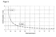
- the characteristic of the actuator is selected so that the maximum amplitude of the incoming received signal is mapped to a predetermined, the amplifier preferably as fully exploitable amplitude of the amplified received signal.
- FIG. 5 shows an example of a characteristic of the actuator of the amplifier 24. This characteristic is tuned so that at the output of the actuator for all input pulses at least an approximately constant and preferably maximum amplitude is given. With dashed lines are the gain factors or Gains for in the FIGS. 3 and 4 illustrated exemplary photocurrents of 0.1 uA and 0.5 uA illustrated.
Landscapes
- Engineering & Computer Science (AREA)
- Physics & Mathematics (AREA)
- Computer Networks & Wireless Communication (AREA)
- General Physics & Mathematics (AREA)
- Radar, Positioning & Navigation (AREA)
- Remote Sensing (AREA)
- Electromagnetism (AREA)
- Optical Radar Systems And Details Thereof (AREA)
Priority Applications (1)
| Application Number | Priority Date | Filing Date | Title |
|---|---|---|---|
| EP08105703A EP2182379B1 (fr) | 2008-10-30 | 2008-10-30 | Scanner laser mesurant l'éloignement |
Applications Claiming Priority (1)
| Application Number | Priority Date | Filing Date | Title |
|---|---|---|---|
| EP08105703A EP2182379B1 (fr) | 2008-10-30 | 2008-10-30 | Scanner laser mesurant l'éloignement |
Publications (2)
| Publication Number | Publication Date |
|---|---|
| EP2182379A1 true EP2182379A1 (fr) | 2010-05-05 |
| EP2182379B1 EP2182379B1 (fr) | 2012-09-19 |
Family
ID=40456737
Family Applications (1)
| Application Number | Title | Priority Date | Filing Date |
|---|---|---|---|
| EP08105703A Active EP2182379B1 (fr) | 2008-10-30 | 2008-10-30 | Scanner laser mesurant l'éloignement |
Country Status (1)
| Country | Link |
|---|---|
| EP (1) | EP2182379B1 (fr) |
Cited By (4)
| Publication number | Priority date | Publication date | Assignee | Title |
|---|---|---|---|---|
| EP2395368A1 (fr) | 2010-06-11 | 2011-12-14 | Sick AG | Scanner laser mesurant l'éloignement destiné à la détection d'objets dans une zone de surveillance |
| DE102014102209A1 (de) | 2014-02-20 | 2015-08-20 | Sick Ag | Entfernungsmessender Sensor und Verfahren zur Abstandsbestimmung von Objekten in einem Ueberwachungsbereich |
| WO2019040176A1 (fr) * | 2017-08-22 | 2019-02-28 | Microsoft Technology Licensing, Llc | Scanner de ligne mems et caméra de pixel fondée sur un photomultiplicateur au silicium pour imagerie de l'œil à faible plage dynamique de lumière |
| KR20190073988A (ko) * | 2017-12-19 | 2019-06-27 | 삼성전자주식회사 | 거리 측정 장치 및 그 방법 |
Families Citing this family (3)
| Publication number | Priority date | Publication date | Assignee | Title |
|---|---|---|---|---|
| CN107843903B (zh) * | 2017-10-27 | 2021-05-11 | 天津津航技术物理研究所 | 一种多阀值tdc高精度激光脉冲测距方法 |
| DE202019100793U1 (de) | 2019-02-12 | 2020-05-15 | Sick Ag | Optoelektronischer Sensor zur Erfassung von Objekten |
| DE102020211394A1 (de) | 2020-09-10 | 2022-03-10 | Volkswagen Aktiengesellschaft | Vorrichtung und Verfahren zur Positionsbestimmung eines Werkstücks |
Citations (6)
| Publication number | Priority date | Publication date | Assignee | Title |
|---|---|---|---|---|
| DE4340756A1 (de) | 1992-12-08 | 1994-06-09 | Sick Optik Elektronik Erwin | Laserabstandsermittlungsvorrichtung |
| EP0782007A2 (fr) * | 1995-12-27 | 1997-07-02 | Denso Corporation | Système et dispositif pour mesurer la distance |
| EP0848495A2 (fr) * | 1996-12-11 | 1998-06-17 | Fujitsu Limited | Circuit amplificateur de signaux |
| US6439460B1 (en) * | 2000-12-15 | 2002-08-27 | Yu-Chun Chang | Instant synchronous automatic gain control apparatus |
| EP1795913A2 (fr) * | 2005-12-08 | 2007-06-13 | Omron Corporation | Dispositif de scanner laser |
| EP1936400A1 (fr) | 2006-12-20 | 2008-06-25 | Sick Ag | Lecteur laser |
Family Cites Families (1)
| Publication number | Priority date | Publication date | Assignee | Title |
|---|---|---|---|---|
| WO2009039875A1 (fr) * | 2007-09-28 | 2009-04-02 | Trimble 3D Scanning | Instrument et procédé de mesure de distance |
-
2008
- 2008-10-30 EP EP08105703A patent/EP2182379B1/fr active Active
Patent Citations (6)
| Publication number | Priority date | Publication date | Assignee | Title |
|---|---|---|---|---|
| DE4340756A1 (de) | 1992-12-08 | 1994-06-09 | Sick Optik Elektronik Erwin | Laserabstandsermittlungsvorrichtung |
| EP0782007A2 (fr) * | 1995-12-27 | 1997-07-02 | Denso Corporation | Système et dispositif pour mesurer la distance |
| EP0848495A2 (fr) * | 1996-12-11 | 1998-06-17 | Fujitsu Limited | Circuit amplificateur de signaux |
| US6439460B1 (en) * | 2000-12-15 | 2002-08-27 | Yu-Chun Chang | Instant synchronous automatic gain control apparatus |
| EP1795913A2 (fr) * | 2005-12-08 | 2007-06-13 | Omron Corporation | Dispositif de scanner laser |
| EP1936400A1 (fr) | 2006-12-20 | 2008-06-25 | Sick Ag | Lecteur laser |
Cited By (7)
| Publication number | Priority date | Publication date | Assignee | Title |
|---|---|---|---|---|
| EP2395368A1 (fr) | 2010-06-11 | 2011-12-14 | Sick AG | Scanner laser mesurant l'éloignement destiné à la détection d'objets dans une zone de surveillance |
| DE102014102209A1 (de) | 2014-02-20 | 2015-08-20 | Sick Ag | Entfernungsmessender Sensor und Verfahren zur Abstandsbestimmung von Objekten in einem Ueberwachungsbereich |
| EP2910972A1 (fr) | 2014-02-20 | 2015-08-26 | Sick Ag | Capteur mesurant l'éloignement et procédé destiné à la détermination de distance d'objets dans une zone de surveillance |
| WO2019040176A1 (fr) * | 2017-08-22 | 2019-02-28 | Microsoft Technology Licensing, Llc | Scanner de ligne mems et caméra de pixel fondée sur un photomultiplicateur au silicium pour imagerie de l'œil à faible plage dynamique de lumière |
| US20190064922A1 (en) * | 2017-08-22 | 2019-02-28 | Microsoft Technology Licensing, Llc | Mems line scanner and silicon photomultiplier based pixel camera for low light large dynamic range eye imaging |
| US10635168B2 (en) | 2017-08-22 | 2020-04-28 | Microsoft Technology Licensing, Llc | MEMS line scanner and silicon photomultiplier based pixel camera for low light large dynamic range eye imaging |
| KR20190073988A (ko) * | 2017-12-19 | 2019-06-27 | 삼성전자주식회사 | 거리 측정 장치 및 그 방법 |
Also Published As
| Publication number | Publication date |
|---|---|
| EP2182379B1 (fr) | 2012-09-19 |
Similar Documents
| Publication | Publication Date | Title |
|---|---|---|
| EP2182377B1 (fr) | Scanner laser mesurant l'éloignement | |
| EP1936400B1 (fr) | Lecteur laser | |
| EP0793115B1 (fr) | Radar à laser à résolution millimétrique | |
| DE102014100696B3 (de) | Entfernungsmessender Sensor und Verfahren zur Erfassung und Abstandsbestimmung von Objekten | |
| EP2182379B1 (fr) | Scanner laser mesurant l'éloignement | |
| DE102011056963B3 (de) | Messung von Entfernungen nach dem Signallaufzeitprinzip | |
| EP2395368B1 (fr) | Scanner laser mesurant l'éloignement destiné à la détection d'objets dans une zone de surveillance | |
| DE2216765C3 (de) | Verfahren und Einrichtung zur Entfernungsmessung | |
| EP1308693B1 (fr) | Dispositif optoélectronique de mesure de distance | |
| EP2088453B1 (fr) | Capteur optoélectronique destiné à la mesure d'éloignement | |
| DE102007013714A1 (de) | Optoelektronischer Sensor und Verfahren zur Messung einer Entfernung oder einer Entfernungsänderung | |
| EP2182378A1 (fr) | Scanner laser mesurant l'éloignement | |
| DE102013100696B3 (de) | Optoelektronischer Sensor und Verfahren zur Erfassung von Objekten in einem Überwachungsbereich | |
| DE102009029364A1 (de) | Messvorrichtung zur Messung einer Entfernung zwischen der Messvorrichtung und einem Zielobjekt mit Hilfe optischer Messstrahlung | |
| DE102010061382A1 (de) | Optoelektronischer Sensor und Verfahren zur Erfassung und Abstandsbestimmung von Objekten | |
| EP3770633B1 (fr) | Capteur optoélectronique et procédé de détermination de distance | |
| WO2014060156A1 (fr) | Système de détection optoélectronique à consommation d'énergie réduite, véhicule à moteur et procédé correspondant | |
| DE102015100910A1 (de) | Vorrichtung und Verfahren zum Erfassen von Objekten für ein Kraftfahrzeug | |
| DE4108376C2 (de) | Verfahren und Schaltungsanordnung zur Erfassung und Auswertung von Signalen bei der Entfernungsmessung | |
| DE102019127667A1 (de) | Entfernungsmessender optoelektronischer Sensor und Verfahren zur Erfassung eines Zielobjekts | |
| DE10138531A1 (de) | Verfahren und Vorrichtung zur Aufnahme eines dreidimensionalen Abstandsbildes | |
| DE2659204C2 (de) | Verfahren und Vorrichtung zur Ortung eines Ziel-Objektes | |
| EP1843171B1 (fr) | Dispositif de mesure de distances | |
| EP2910972B1 (fr) | Capteur mesurant l'éloignement et procédé destiné à la détermination de distance d'objets dans une zone de surveillance | |
| EP3361282B1 (fr) | Capteur optique avec circuit limiteur |
Legal Events
| Date | Code | Title | Description |
|---|---|---|---|
| PUAI | Public reference made under article 153(3) epc to a published international application that has entered the european phase |
Free format text: ORIGINAL CODE: 0009012 |
|
| AK | Designated contracting states |
Kind code of ref document: A1 Designated state(s): AT BE BG CH CY CZ DE DK EE ES FI FR GB GR HR HU IE IS IT LI LT LU LV MC MT NL NO PL PT RO SE SI SK TR |
|
| AX | Request for extension of the european patent |
Extension state: AL BA MK RS |
|
| 17P | Request for examination filed |
Effective date: 20100621 |
|
| AKX | Designation fees paid |
Designated state(s): AT BE BG CH CY CZ DE DK EE ES FI FR GB GR HR HU IE IS IT LI LT LU LV MC MT NL NO PL PT RO SE SI SK TR |
|
| 17Q | First examination report despatched |
Effective date: 20120207 |
|
| GRAP | Despatch of communication of intention to grant a patent |
Free format text: ORIGINAL CODE: EPIDOSNIGR1 |
|
| RIC1 | Information provided on ipc code assigned before grant |
Ipc: G01S 7/489 20060101AFI20120404BHEP Ipc: H03G 3/30 20060101ALI20120404BHEP |
|
| GRAS | Grant fee paid |
Free format text: ORIGINAL CODE: EPIDOSNIGR3 |
|
| GRAA | (expected) grant |
Free format text: ORIGINAL CODE: 0009210 |
|
| AK | Designated contracting states |
Kind code of ref document: B1 Designated state(s): AT BE BG CH CY CZ DE DK EE ES FI FR GB GR HR HU IE IS IT LI LT LU LV MC MT NL NO PL PT RO SE SI SK TR |
|
| REG | Reference to a national code |
Ref country code: GB Ref legal event code: FG4D Free format text: NOT ENGLISH |
|
| REG | Reference to a national code |
Ref country code: CH Ref legal event code: EP |
|
| REG | Reference to a national code |
Ref country code: IE Ref legal event code: FG4D Free format text: LANGUAGE OF EP DOCUMENT: GERMAN |
|
| REG | Reference to a national code |
Ref country code: AT Ref legal event code: REF Ref document number: 576282 Country of ref document: AT Kind code of ref document: T Effective date: 20121015 |
|
| REG | Reference to a national code |
Ref country code: SE Ref legal event code: TRGR |
|
| REG | Reference to a national code |
Ref country code: DE Ref legal event code: R096 Ref document number: 502008008215 Country of ref document: DE Effective date: 20121108 |
|
| PG25 | Lapsed in a contracting state [announced via postgrant information from national office to epo] |
Ref country code: FI Free format text: LAPSE BECAUSE OF FAILURE TO SUBMIT A TRANSLATION OF THE DESCRIPTION OR TO PAY THE FEE WITHIN THE PRESCRIBED TIME-LIMIT Effective date: 20120919 Ref country code: LT Free format text: LAPSE BECAUSE OF FAILURE TO SUBMIT A TRANSLATION OF THE DESCRIPTION OR TO PAY THE FEE WITHIN THE PRESCRIBED TIME-LIMIT Effective date: 20120919 Ref country code: NO Free format text: LAPSE BECAUSE OF FAILURE TO SUBMIT A TRANSLATION OF THE DESCRIPTION OR TO PAY THE FEE WITHIN THE PRESCRIBED TIME-LIMIT Effective date: 20121219 Ref country code: HR Free format text: LAPSE BECAUSE OF FAILURE TO SUBMIT A TRANSLATION OF THE DESCRIPTION OR TO PAY THE FEE WITHIN THE PRESCRIBED TIME-LIMIT Effective date: 20120919 |
|
| REG | Reference to a national code |
Ref country code: NL Ref legal event code: VDEP Effective date: 20120919 |
|
| REG | Reference to a national code |
Ref country code: LT Ref legal event code: MG4D Effective date: 20120919 |
|
| PG25 | Lapsed in a contracting state [announced via postgrant information from national office to epo] |
Ref country code: SI Free format text: LAPSE BECAUSE OF FAILURE TO SUBMIT A TRANSLATION OF THE DESCRIPTION OR TO PAY THE FEE WITHIN THE PRESCRIBED TIME-LIMIT Effective date: 20120919 Ref country code: LV Free format text: LAPSE BECAUSE OF FAILURE TO SUBMIT A TRANSLATION OF THE DESCRIPTION OR TO PAY THE FEE WITHIN THE PRESCRIBED TIME-LIMIT Effective date: 20120919 Ref country code: GR Free format text: LAPSE BECAUSE OF FAILURE TO SUBMIT A TRANSLATION OF THE DESCRIPTION OR TO PAY THE FEE WITHIN THE PRESCRIBED TIME-LIMIT Effective date: 20121220 |
|
| BERE | Be: lapsed |
Owner name: SICK A.G. Effective date: 20121031 |
|
| PG25 | Lapsed in a contracting state [announced via postgrant information from national office to epo] |
Ref country code: RO Free format text: LAPSE BECAUSE OF FAILURE TO SUBMIT A TRANSLATION OF THE DESCRIPTION OR TO PAY THE FEE WITHIN THE PRESCRIBED TIME-LIMIT Effective date: 20120919 Ref country code: EE Free format text: LAPSE BECAUSE OF FAILURE TO SUBMIT A TRANSLATION OF THE DESCRIPTION OR TO PAY THE FEE WITHIN THE PRESCRIBED TIME-LIMIT Effective date: 20120919 Ref country code: ES Free format text: LAPSE BECAUSE OF FAILURE TO SUBMIT A TRANSLATION OF THE DESCRIPTION OR TO PAY THE FEE WITHIN THE PRESCRIBED TIME-LIMIT Effective date: 20121230 Ref country code: IS Free format text: LAPSE BECAUSE OF FAILURE TO SUBMIT A TRANSLATION OF THE DESCRIPTION OR TO PAY THE FEE WITHIN THE PRESCRIBED TIME-LIMIT Effective date: 20130119 Ref country code: CZ Free format text: LAPSE BECAUSE OF FAILURE TO SUBMIT A TRANSLATION OF THE DESCRIPTION OR TO PAY THE FEE WITHIN THE PRESCRIBED TIME-LIMIT Effective date: 20120919 Ref country code: NL Free format text: LAPSE BECAUSE OF FAILURE TO SUBMIT A TRANSLATION OF THE DESCRIPTION OR TO PAY THE FEE WITHIN THE PRESCRIBED TIME-LIMIT Effective date: 20120919 |
|
| PG25 | Lapsed in a contracting state [announced via postgrant information from national office to epo] |
Ref country code: PT Free format text: LAPSE BECAUSE OF FAILURE TO SUBMIT A TRANSLATION OF THE DESCRIPTION OR TO PAY THE FEE WITHIN THE PRESCRIBED TIME-LIMIT Effective date: 20130121 Ref country code: SK Free format text: LAPSE BECAUSE OF FAILURE TO SUBMIT A TRANSLATION OF THE DESCRIPTION OR TO PAY THE FEE WITHIN THE PRESCRIBED TIME-LIMIT Effective date: 20120919 Ref country code: MC Free format text: LAPSE BECAUSE OF NON-PAYMENT OF DUE FEES Effective date: 20121031 Ref country code: PL Free format text: LAPSE BECAUSE OF FAILURE TO SUBMIT A TRANSLATION OF THE DESCRIPTION OR TO PAY THE FEE WITHIN THE PRESCRIBED TIME-LIMIT Effective date: 20120919 |
|
| PLBE | No opposition filed within time limit |
Free format text: ORIGINAL CODE: 0009261 |
|
| STAA | Information on the status of an ep patent application or granted ep patent |
Free format text: STATUS: NO OPPOSITION FILED WITHIN TIME LIMIT |
|
| PG25 | Lapsed in a contracting state [announced via postgrant information from national office to epo] |
Ref country code: BG Free format text: LAPSE BECAUSE OF FAILURE TO SUBMIT A TRANSLATION OF THE DESCRIPTION OR TO PAY THE FEE WITHIN THE PRESCRIBED TIME-LIMIT Effective date: 20121219 Ref country code: BE Free format text: LAPSE BECAUSE OF NON-PAYMENT OF DUE FEES Effective date: 20121031 Ref country code: DK Free format text: LAPSE BECAUSE OF FAILURE TO SUBMIT A TRANSLATION OF THE DESCRIPTION OR TO PAY THE FEE WITHIN THE PRESCRIBED TIME-LIMIT Effective date: 20120919 |
|
| REG | Reference to a national code |
Ref country code: IE Ref legal event code: MM4A |
|
| 26N | No opposition filed |
Effective date: 20130620 |
|
| GBPC | Gb: european patent ceased through non-payment of renewal fee |
Effective date: 20121219 |
|
| REG | Reference to a national code |
Ref country code: DE Ref legal event code: R097 Ref document number: 502008008215 Country of ref document: DE Effective date: 20130620 |
|
| PG25 | Lapsed in a contracting state [announced via postgrant information from national office to epo] |
Ref country code: IE Free format text: LAPSE BECAUSE OF NON-PAYMENT OF DUE FEES Effective date: 20121030 |
|
| PG25 | Lapsed in a contracting state [announced via postgrant information from national office to epo] |
Ref country code: MT Free format text: LAPSE BECAUSE OF FAILURE TO SUBMIT A TRANSLATION OF THE DESCRIPTION OR TO PAY THE FEE WITHIN THE PRESCRIBED TIME-LIMIT Effective date: 20120919 Ref country code: CY Free format text: LAPSE BECAUSE OF FAILURE TO SUBMIT A TRANSLATION OF THE DESCRIPTION OR TO PAY THE FEE WITHIN THE PRESCRIBED TIME-LIMIT Effective date: 20120919 Ref country code: GB Free format text: LAPSE BECAUSE OF NON-PAYMENT OF DUE FEES Effective date: 20121219 |
|
| PGFP | Annual fee paid to national office [announced via postgrant information from national office to epo] |
Ref country code: SE Payment date: 20131022 Year of fee payment: 6 Ref country code: CH Payment date: 20131023 Year of fee payment: 6 Ref country code: AT Payment date: 20131021 Year of fee payment: 6 |
|
| PG25 | Lapsed in a contracting state [announced via postgrant information from national office to epo] |
Ref country code: TR Free format text: LAPSE BECAUSE OF FAILURE TO SUBMIT A TRANSLATION OF THE DESCRIPTION OR TO PAY THE FEE WITHIN THE PRESCRIBED TIME-LIMIT Effective date: 20120919 |
|
| PG25 | Lapsed in a contracting state [announced via postgrant information from national office to epo] |
Ref country code: LU Free format text: LAPSE BECAUSE OF NON-PAYMENT OF DUE FEES Effective date: 20121030 |
|
| PG25 | Lapsed in a contracting state [announced via postgrant information from national office to epo] |
Ref country code: HU Free format text: LAPSE BECAUSE OF FAILURE TO SUBMIT A TRANSLATION OF THE DESCRIPTION OR TO PAY THE FEE WITHIN THE PRESCRIBED TIME-LIMIT Effective date: 20081030 |
|
| REG | Reference to a national code |
Ref country code: CH Ref legal event code: PL |
|
| REG | Reference to a national code |
Ref country code: SE Ref legal event code: EUG |
|
| REG | Reference to a national code |
Ref country code: AT Ref legal event code: MM01 Ref document number: 576282 Country of ref document: AT Kind code of ref document: T Effective date: 20141030 |
|
| PG25 | Lapsed in a contracting state [announced via postgrant information from national office to epo] |
Ref country code: LI Free format text: LAPSE BECAUSE OF NON-PAYMENT OF DUE FEES Effective date: 20141031 Ref country code: CH Free format text: LAPSE BECAUSE OF NON-PAYMENT OF DUE FEES Effective date: 20141031 Ref country code: SE Free format text: LAPSE BECAUSE OF NON-PAYMENT OF DUE FEES Effective date: 20141031 |
|
| PG25 | Lapsed in a contracting state [announced via postgrant information from national office to epo] |
Ref country code: AT Free format text: LAPSE BECAUSE OF NON-PAYMENT OF DUE FEES Effective date: 20141030 |
|
| REG | Reference to a national code |
Ref country code: FR Ref legal event code: PLFP Year of fee payment: 8 |
|
| PGFP | Annual fee paid to national office [announced via postgrant information from national office to epo] |
Ref country code: FR Payment date: 20151026 Year of fee payment: 8 |
|
| REG | Reference to a national code |
Ref country code: FR Ref legal event code: ST Effective date: 20170630 |
|
| PG25 | Lapsed in a contracting state [announced via postgrant information from national office to epo] |
Ref country code: FR Free format text: LAPSE BECAUSE OF NON-PAYMENT OF DUE FEES Effective date: 20161102 |
|
| PGFP | Annual fee paid to national office [announced via postgrant information from national office to epo] |
Ref country code: IT Payment date: 20181022 Year of fee payment: 11 |
|
| PG25 | Lapsed in a contracting state [announced via postgrant information from national office to epo] |
Ref country code: IT Free format text: LAPSE BECAUSE OF NON-PAYMENT OF DUE FEES Effective date: 20191030 |
|
| PGFP | Annual fee paid to national office [announced via postgrant information from national office to epo] |
Ref country code: DE Payment date: 20231018 Year of fee payment: 16 |