EP2910972B1 - Distance measuring sensor and method for determing the distance from objects in a monitoring zone - Google Patents
Distance measuring sensor and method for determing the distance from objects in a monitoring zone Download PDFInfo
- Publication number
- EP2910972B1 EP2910972B1 EP15151418.9A EP15151418A EP2910972B1 EP 2910972 B1 EP2910972 B1 EP 2910972B1 EP 15151418 A EP15151418 A EP 15151418A EP 2910972 B1 EP2910972 B1 EP 2910972B1
- Authority
- EP
- European Patent Office
- Prior art keywords
- signal
- sensor
- voltage
- unit
- distance
- Prior art date
- Legal status (The legal status is an assumption and is not a legal conclusion. Google has not performed a legal analysis and makes no representation as to the accuracy of the status listed.)
- Active
Links
Images


Classifications
-
- G—PHYSICS
- G01—MEASURING; TESTING
- G01S—RADIO DIRECTION-FINDING; RADIO NAVIGATION; DETERMINING DISTANCE OR VELOCITY BY USE OF RADIO WAVES; LOCATING OR PRESENCE-DETECTING BY USE OF THE REFLECTION OR RERADIATION OF RADIO WAVES; ANALOGOUS ARRANGEMENTS USING OTHER WAVES
- G01S17/00—Systems using the reflection or reradiation of electromagnetic waves other than radio waves, e.g. lidar systems
- G01S17/02—Systems using the reflection of electromagnetic waves other than radio waves
- G01S17/06—Systems determining position data of a target
- G01S17/08—Systems determining position data of a target for measuring distance only
- G01S17/10—Systems determining position data of a target for measuring distance only using transmission of interrupted, pulse-modulated waves
-
- G—PHYSICS
- G01—MEASURING; TESTING
- G01S—RADIO DIRECTION-FINDING; RADIO NAVIGATION; DETERMINING DISTANCE OR VELOCITY BY USE OF RADIO WAVES; LOCATING OR PRESENCE-DETECTING BY USE OF THE REFLECTION OR RERADIATION OF RADIO WAVES; ANALOGOUS ARRANGEMENTS USING OTHER WAVES
- G01S7/00—Details of systems according to groups G01S13/00, G01S15/00, G01S17/00
- G01S7/48—Details of systems according to groups G01S13/00, G01S15/00, G01S17/00 of systems according to group G01S17/00
- G01S7/483—Details of pulse systems
- G01S7/486—Receivers
- G01S7/4861—Circuits for detection, sampling, integration or read-out
-
- G—PHYSICS
- G01—MEASURING; TESTING
- G01S—RADIO DIRECTION-FINDING; RADIO NAVIGATION; DETERMINING DISTANCE OR VELOCITY BY USE OF RADIO WAVES; LOCATING OR PRESENCE-DETECTING BY USE OF THE REFLECTION OR RERADIATION OF RADIO WAVES; ANALOGOUS ARRANGEMENTS USING OTHER WAVES
- G01S7/00—Details of systems according to groups G01S13/00, G01S15/00, G01S17/00
- G01S7/48—Details of systems according to groups G01S13/00, G01S15/00, G01S17/00 of systems according to group G01S17/00
- G01S7/483—Details of pulse systems
- G01S7/486—Receivers
- G01S7/4865—Time delay measurement, e.g. time-of-flight measurement, time of arrival measurement or determining the exact position of a peak
-
- G—PHYSICS
- G01—MEASURING; TESTING
- G01S—RADIO DIRECTION-FINDING; RADIO NAVIGATION; DETERMINING DISTANCE OR VELOCITY BY USE OF RADIO WAVES; LOCATING OR PRESENCE-DETECTING BY USE OF THE REFLECTION OR RERADIATION OF RADIO WAVES; ANALOGOUS ARRANGEMENTS USING OTHER WAVES
- G01S7/00—Details of systems according to groups G01S13/00, G01S15/00, G01S17/00
- G01S7/48—Details of systems according to groups G01S13/00, G01S15/00, G01S17/00 of systems according to group G01S17/00
- G01S7/497—Means for monitoring or calibrating
Definitions
- the invention relates to a distance-measuring sensor and a method for detecting and determining the distance of objects in a monitoring area according to the preamble of claims 1 and 10, respectively.
- Numerous sensors use a signal transit time principle in which the time interval between transmission and reception of a signal is converted into a distance over the signal propagation time. In this way, different frequency ranges of the electromagnetic spectrum such as microwaves and light and also other physical signals such as ultrasound are utilized.
- optoelectronic sensors according to the principle of the light transit time method light signals are emitted, and the time until reception of the light signals reflected or reflected on objects is measured. Due to the constant propagation speed of the signal, the signal transit time can be converted directly into a distance.
- Optoelectronic distance measurement can be required for example in vehicle safety, logistics or factory automation or safety technology. In most cases, the desired output size is the measured distance.
- a rangefinder according to the light transit time method can also operate switching by detecting a change in distance of a reflector expected at a specific distance or of a reflecting or remitting object.
- a special application is a reflection light barrier with monitoring of the distance to its reflector.
- the light transit time method is also the principle by which distance-measuring laser scanners operate, periodically scanning a surveillance plane or even a three-dimensional space area. If several distance detectors are combined next to each other, a time-of-flight camera is created takes three-dimensional image data. In this case, integrated image sensors can be formed, which make the distance measurement in their pixels.
- Precondition for an accurate signal propagation time measurement is the precise determination of the reception time.
- various methods are known.
- a phase method a periodically modulated signal is transmitted and the phase shift between transmitted and received signals is determined.
- a pulse method uses a signal that allows accurate timing. The detection takes place in the simplest case by comparator thresholds, in more complex processes, the entire received signal is sampled and evaluated digitally to locate the received pulse.
- a pulse averaging method transmits a plurality of transmit pulses and statistically evaluates the subsequently received pulses.
- the light signal is first converted into an electrical signal and amplified in an analog electronic circuit. Since a photodetector generates a photocurrent, a transimpedance amplifier is used as the first amplifier stage, so that subsequently voltage signals are available.
- the signal echo to be detected can come from objects with very different reflective or scattering properties and brightness, and also from short distances of a few centimeters or distances of many meters or even kilometers.
- the signal transit time method is very universal and can deal with this variety in itself.
- the different measurement conditions result in a very large dynamic range, which can for example be up to 120 dB and more for laser scanners.
- sensitive optical detectors such as PIN diodes or avalanche diodes (APDs) are capable of detecting even the smallest of optical signals, dynamic range is a major challenge for electronics.
- the EP 2 182 379 A1 here goes one step further and uses information from the measuring pulse itself to adjust the gain by the received signal for the actual evaluation is slowed down by a delay line, so that the gain can be adjusted in time.
- each of the amplifier in view of the shortness of the light pulses and the repeated measurements quickly and without delay adjust.
- the dynamic range is split into multiple paths with complementary gain ranges. From the above numbers of 30-40 dB per channel and a desired dynamic range of 120 dB results that at least three channels are required for this. Even more serious, however, is that the individual channels influence each other. The consequences are increased noise, increased susceptibility to interference and a reduced detection capability.
- the US 5,359,404 discloses a laser-based velocity measuring device that can perform range finding according to a pulse transit time method.
- a high voltage power supply provides the power to emit the laser pulses and biases the light receiver.
- the invention is based on the basic concept of developing additional measurement information independently of the actual received signal.
- a voltage dip of a bias unit of the receiver is measured and this signal for a light transit time measurement used.
- the reception time is therefore not or at least not exclusively determined from the actual received signal, but closed indirectly from the voltage dip on the reception time of the reflected signal on the receiver.
- the reception time need not be explicitly determined, since only the relative time interval is interested in a transmission time.
- the received signal is not affected by this evaluation of the voltage dip of the bias unit and is available without restriction for any further analog and digital evaluation steps.
- the invention has the advantage that, in addition to the amplified received signal itself, additional measurement information becomes available for the received signal. This can be used to extend the dynamic range.
- the evaluation unit is preferably designed to determine the light transit time in multiple channels on the basis of the received signal and the voltage dip signal.
- the received signal and the voltage dip signal are thus understood as two measuring channels. This can be used for a redundant or diversified measurement, or the results of the two measurement channels are compared or billed.
- the measuring channels are used to process different signal strengths in each case, so that the overall result is a significantly expanded dynamic range within which the time of reception and the amplitude of the remitted signal can be determined precisely and at least largely without amplification artifacts.
- a first amplifier is preferably provided in order to generate an amplified voltage signal from the received signal.
- this involves a transimpedance amplifier in order to generate the further voltage signal to be evaluated from a photocurrent of the receiver.
- the first amplifier is more preferably very sensitive to detect weak remitted signals. In this case, the strong remitted signals are complementarily detected via the voltage dip signal.
- the voltage measuring unit preferably has a second amplifier.
- the voltage drop signal in an adjustable specific portion of the dynamic range to be covered at least largely linearly detected.
- the first amplifier and the second amplifier preferably have matched gain factors so that the received signal and the voltage dip signal are detected in different sensitivity ranges.
- the voltage drop signal is weak or not amplified, so that the realized via the voltage drop of the bias unit additional measuring channel is responsible for the detection of strong remittierter signals.
- the actual received signal is amplified with a high amplification factor so that this measuring channel can process weakly remitted signals.
- This division has the advantage that because of the different detection principles, the strong signals detected by the voltage dip do not affect the evaluation of the weak signals.
- other settings of the amplification factors and thus other partitions of the measurement channels are also conceivable, including a little or even largely overlapping regions for a redundant data acquisition.
- the receiver is preferably an avalanche photodiode and the bias unit generates a high voltage.
- the avalanche photodiode is particularly suitable for optical detection over a wide dynamic range up to very weak signals. For this purpose, a high-voltage supply for biasing with a few hundred volts or more is needed, the break-in can be reliably detected upon detection of a signal as a voltage dip signal.
- the biasing unit preferably has a charging capacitor. Thereby, the voltage and also the high voltage of the bias unit after a detection, such as avalanche breakdown of an avalanche photodiode, restored.
- the biasing unit preferably has a resistance between the charging capacitor and ground, wherein the voltage measuring unit detects the voltage drop-in signal at the resistor.
- the tapped voltage drop signal is proportional to the current of the receiver, the waveforms of voltage dip signal and received signal thus correspond to each other without further filtering measures.
- the biasing unit preferably has a high-pass filter. This serves to filter out low-frequency components of the voltage breakdown signal, for example the comparatively slow charging of the charging capacitor.
- a suitable cutoff frequency which is adapted to the signal shape of the transmission signal results Then for the voltage drop signal a signal waveform comparable to the received signal, which simplifies the common or complementary evaluation in the two measurement channels.
- inventive method can be configured in a similar manner by further features and shows similar advantages. Such further features are exemplary, but not exhaustive, in which subclaims following the independent claims are described.
- FIG. 12 shows a block diagram of a distance-measuring sensor 10 in one embodiment as a one-dimensional opto-electronic distance sensor.
- a light transmitter 12 sends a light signal 16 via a transmission optical system 14 into a monitoring area 18.
- the light signal 16 when an object 20 is in the beam path, is reflected or remitted at this object 20 and returns to the sensor 10 as a remitted light signal 22.
- There it is guided by a receiving optical system 24 to a light receiver 26.
- the optical arrangement is to be understood purely by way of example, the invention also includes other arrangements, for example with divider mirrors or a light emitter in the cone of the light receiver.
- the explanation of a one-dimensional optoelectronic sensor is to be understood only as an example, as well as the sensor can be a multi-dimensional system, such as a laser scanner or a light runtime camera, or work with entirely different signals such as microwaves or ultrasound.
- the light receiver 26 is, for example, a PIN diode or an avalanche photodiode and biased by means of a biasing unit 28. If a remitted light signal 22 hits the photosensitive surface of the light receiver 26, a corresponding photocurrent is generated.
- the photocurrent is converted, for example with suitable transimpedance conversion in a voltage signal and fed to an evaluation unit 30, which is preferably at the same time responsible for the control tasks of the sensor 10. This can be an analog circuit, but usually the received signal is still digitized and the evaluation unit 30 is implemented on a digital evaluation module, such as a microprocessor or an FPGA (Field Programmable Gate Array).
- a short pulse generally at least one signal with a clearly identifiable time reference is transmitted. Accordingly, the echoes of objects 20 or interferers in the surveillance area 18 also have this waveform.
- the evaluation unit 30 determines the reception time from the reception signal by a threshold value method, by a search in the digitally present reception signal on the basis of the known transmission signal form or another method. It is also conceivable to emit a plurality of transmit pulses, which then collect received receive pulses and thus to determine a reception time by statistical means.
- the result of the evaluation is in each case the delay of the received signal relative to the transmission signal, that is to say the signal propagation time. With the help of the known propagation speed, in this case the speed of light, in other cases, for example, the speed of sound, the signal propagation time can be converted directly into a distance of the object 20.
- the transmit pulses are very short, or alternatively at least transmit signals with steep edges are used for the precise detection of a receive time, the photocurrent must be processed by an amplifier with sufficient bandwidth so as not to falsify the waveform.
- an amplitude range in the order of magnitude of 120 dB should also be detectable even with the least possible noise.
- the invention therefore has a circuit which utilizes the onset of photodiode high voltage, generally a voltage dip on the bias unit 28, for detection.
- a tension measuring unit 32 with the biasing unit 28 connected, which measures a voltage drop signal and passes to the evaluation unit 30.
- the voltage drop signal carries in principle the same information as the received signal, so that the evaluation unit 30 can perform the same evaluations thereon, in particular a distance measurement, but also a level determination and the like.
- the voltage dip signal and the received signal form the basis for two mutually complementary complementary receiving or measuring channels, so that overall a larger dynamic range is covered.
- the distance measurement takes place solely on the basis of the voltage breakdown signal. This can be useful, for example, if the received signal is needed for a completely different measurement and is therefore not available for a distance measurement.
- the measuring channels formed by the received signal or the voltage dip signal once more multi-channel, for example, to divide the total dynamic range to be covered in more than two sub-areas, or to provide an automatic gain control in these measurement channels.
- FIG. 2 shows a circuit diagram of an embodiment of the analog signal detection of the sensor 10.
- the photocurrent of the light receiver 26 is passed via a transimpedance amplifier 34 and possible further, not shown, amplifier stages as a received signal to the evaluation unit 30.
- the light receiver 26 is biased by means of the bias unit 28 and a charge capacitor 36 provided therein.
- the generation of the photocurrent leads to a collapse of the voltage in the biasing unit 28.
- This is detected by the voltage measuring unit 32 as a voltage drop signal and supplied accordingly as additional or alternative measurement information of the evaluation unit 30.
- a high-pass filter 38 is connected to suppress the low-frequency components of the voltage dip signal.
- the voltage drop signal can also be amplified by amplifier stages, not shown.
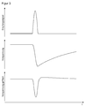
- FIG. 3 shows three purely exemplary signals of the analog signal detection according to FIG. 2 namely, from top to bottom, the photocurrent of the light receiver 26 as the actual received signal, the raw voltage drop signal to the charging capacitor 36 before filtering in the high-pass filter 38 and the voltage drop-in signal detected by the voltage measuring unit 32 after the filtering.
- FIG. 4 shows a circuit diagram of another embodiment of the analog signal detection of the sensor 10.
- the tap of the voltage dip signal is realized without additional AC coupling.
- an additional resistor 40 is connected between the charge capacitor 36 and ground, with the voltage measurement unit 32 measuring the voltage dip signal on this resistor 40. Since the voltage here is proportional to the photocurrent, the signal shape directly corresponds to that of the received signal of the light receiver 26.
- the desired gain of the voltage dip signal can be adjusted in this embodiment by a suitable choice of the resistor 40. Namely, the gain depends on the ratio of the resistor 40 to the resistance between the anode side of the light receiver 26 and ground.
- Another advantage of this embodiment is the direct measurement of the voltage measuring unit 30 to ground.
Description
Die Erfindung betrifft einen entfernungsmessenden Sensor und ein Verfahren zur Erfassung und Abstandsbestimmung von Objekten in einem Überwachungsbereich nach dem Oberbegriff von Anspruch 1 beziehungsweise 10.The invention relates to a distance-measuring sensor and a method for detecting and determining the distance of objects in a monitoring area according to the preamble of
Zahlreiche Sensoren nutzen ein Signallaufzeitprinzip, bei dem das Zeitintervall zwischen Senden und Empfang eines Signals über die Signallaufzeit in eine Entfernung umgerechnet wird. Dabei werden so verschiedene Frequenzbereiche des elektromagnetischen Spektrums wie Mikrowellen und Licht und auch andere physikalische Signale wie Ultraschall ausgenutzt. Bei optoelektronischen Sensoren nach dem Prinzip des Lichtlaufzeitverfahrens werden Lichtsignale ausgesandt, und die Zeit bis zum Empfang der an Objekten remittierten oder reflektierten Lichtsignalen wird gemessen. Aufgrund der konstanten Ausbreitungsgeschwindigkeit des Signals lässt sich die Signallaufzeit unmittelbar in eine Entfernung umrechnen.Numerous sensors use a signal transit time principle in which the time interval between transmission and reception of a signal is converted into a distance over the signal propagation time. In this way, different frequency ranges of the electromagnetic spectrum such as microwaves and light and also other physical signals such as ultrasound are utilized. In optoelectronic sensors according to the principle of the light transit time method, light signals are emitted, and the time until reception of the light signals reflected or reflected on objects is measured. Due to the constant propagation speed of the signal, the signal transit time can be converted directly into a distance.
Optoelektronische Entfernungsmessung kann beispielsweise in der Fahrzeugsicherheit, der Logistik- oder Fabrikautomatisierung oder der Sicherheitstechnik benötigt werden. Meist ist die gesuchte Ausgabegröße der gemessene Abstand. Alternativ kann ein Entfernungsmesser nach dem Lichtlaufzeitverfahren auch schaltend arbeiten, indem eine Entfernungsänderung eines in einem bestimmten Abstand erwarteten Reflektors oder eines reflektierenden oder remittierenden Objekts erkannt wird. Eine besondere Anwendung ist eine Reflexionslichtschranke mit Überwachung des Abstandes zu ihrem Reflektor. Das Lichtlaufzeitverfahren ist auch das Prinzip, nach dem entfernungsmessende Laserscanner arbeiten, die periodisch eine Überwachungsebene oder sogar einen dreidimensionalen Raumbereich abtasten. Fasst man mehrere Entfernungsdetektoren nebeneinander zusammen, so entsteht eine Lichtlaufzeitkamera, die dreidimensionale Bilddaten aufnimmt. Dabei können integrierte Bildsensoren gebildet werden, die in ihren Pixeln die Entfernungsmessung vornehmen.Optoelectronic distance measurement can be required for example in vehicle safety, logistics or factory automation or safety technology. In most cases, the desired output size is the measured distance. Alternatively, a rangefinder according to the light transit time method can also operate switching by detecting a change in distance of a reflector expected at a specific distance or of a reflecting or remitting object. A special application is a reflection light barrier with monitoring of the distance to its reflector. The light transit time method is also the principle by which distance-measuring laser scanners operate, periodically scanning a surveillance plane or even a three-dimensional space area. If several distance detectors are combined next to each other, a time-of-flight camera is created takes three-dimensional image data. In this case, integrated image sensors can be formed, which make the distance measurement in their pixels.
Voraussetzung für eine genaue Signallaufzeitmessung ist die präzise Bestimmung des Empfangszeitpunkts. Dazu sind verschiedene Verfahren bekannt. Bei einem Phasenverfahren wird ein periodisch moduliertes Signal ausgesandt und die Phasenverschiebung zwischen ausgesandtem und empfangenem Signal bestimmt. Ein Pulsverfahren verwendet ein Signal, das eine genaue zeitliche Zuordnung zulässt. Die Erfassung erfolgt hier im einfachsten Fall durch Komparatorschwellen, bei aufwändigeren Verfahren wird das gesamte Empfangssignal abgetastet und digital ausgewertet, um den Empfangspuls zu lokalisieren. Ein Pulsmittelungsverfahren sendet eine Vielzahl von Sendepulsen und wertet die daraufhin empfangenen Pulse statistisch aus.Precondition for an accurate signal propagation time measurement is the precise determination of the reception time. For this purpose, various methods are known. In a phase method, a periodically modulated signal is transmitted and the phase shift between transmitted and received signals is determined. A pulse method uses a signal that allows accurate timing. The detection takes place in the simplest case by comparator thresholds, in more complex processes, the entire received signal is sampled and evaluated digitally to locate the received pulse. A pulse averaging method transmits a plurality of transmit pulses and statistically evaluates the subsequently received pulses.
Unabhängig von der konkreten Auswertung wird zunächst das Lichtsignal in ein elektrisches Signal gewandelt und in einer analogen elektronischen Schaltung nachverstärkt. Da ein Photodetektor einen Photostrom erzeugt, wird als erste Verstärkerstufe ein Transimpedanzverstärker eingesetzt, so dass anschließend Spannungssignale zur Verfügung stehen.Regardless of the specific evaluation, the light signal is first converted into an electrical signal and amplified in an analog electronic circuit. Since a photodetector generates a photocurrent, a transimpedance amplifier is used as the first amplifier stage, so that subsequently voltage signals are available.
Nun kann das zu erfassende Signalecho von Objekten mit sehr unterschiedlichen reflektierenden oder streuenden Eigenschaften und Helligkeiten und zudem aus kurzen Entfernungen von wenigen Zentimetern oder Distanzen von vielen Metern oder sogar Kilometern stammen. Das Signallaufzeitverfahren ist sehr universell und kann mit dieser Vielfalt an sich umgehen. Allerdings resultiert aus den unterschiedlichen Messbedingungen ein sehr großer Dynamikbereich, der beispielsweise bei Laserscannern bis zu 120 dB und mehr umfassen kann. Empfindliche optische Detektoren, wie PIN-Dioden oder Avalanche-Dioden (APD), sind zwar in der Lage, auch kleinste optische Signale zu erfassen, aber für die Elektronik stellt der Dynamikbereich eine sehr große Herausforderung dar. Das gilt gleichermaßen dafür, einer digitalen Signalauswertung ein digitales Signal ausreichender Qualität bereitzustellen, als auch für einfachere Schwellenverfahren, wo die Schwellen ebenfalls über den gesamten Dynamikbereich verteilt werden müssen, um die diversen Mess- und Störechos zu unterscheiden. Bei Verwendung eines statischen Verstärkungsfaktors spiegelt die Signaldynamik den quadratischen Abfall des optischen Signals im Fernfeld wieder und limitiert dadurch die Reichweite des Lichtlaufzeitverfahrens. Ein handelsüblicher Transimpedanzverstärker mit ausreichender Bandbreite deckt ungefähr einen linearen Verstärkungsbereich von 30-40 dB ab und bleibt damit weit hinter den gewünschten 120 dB zurück.Now, the signal echo to be detected can come from objects with very different reflective or scattering properties and brightness, and also from short distances of a few centimeters or distances of many meters or even kilometers. The signal transit time method is very universal and can deal with this variety in itself. However, the different measurement conditions result in a very large dynamic range, which can for example be up to 120 dB and more for laser scanners. Although sensitive optical detectors, such as PIN diodes or avalanche diodes (APDs), are capable of detecting even the smallest of optical signals, dynamic range is a major challenge for electronics. This also applies to digital signal processing provide a digital signal of sufficient quality, as well as simpler threshold methods, where the thresholds must also be distributed over the entire dynamic range in order to distinguish the various measurement and false echoes. Using a static gain factor, the signal dynamics reflect the square decay of the optical signal in the far field, thereby limiting the range of the light transit time method. A commercially available transimpedance amplifier With sufficient bandwidth, it covers approximately a linear gain range of 30-40 dB, far below the desired 120 dB.
Im Stand der Technik sind verschiedene Ansätze bekannt, um mit dem großen Dynamikbereich umzugehen. Am einfachsten wäre die Verwendung nichtlinearer oder logarithmischer Verstärker, die aber für die geforderte Verarbeitung von Pulsen im Nanosekundenbereich mit ausreichender Bandbreite nicht zur Verfügung stehen. Eine andere Möglichkeit besteht darin, die Verstärkung dynamisch von Puls zu Puls anzupassen. In der
Die
In der
Die
Es ist daher Aufgabe der Erfindung, die Entfernungsmessung über einen großen Dynamikbereich zu ermöglichen.It is therefore an object of the invention to enable the distance measurement over a wide dynamic range.
Diese Aufgabe wird durch einen entfernungsmessenden Sensor und ein Verfahren zur Erfassung und Abstandsbestimmung von Objekten in einem Überwachungsbereich nach Anspruch 1 beziehungsweise 10 gelöst. Dabei geht die Erfindung von dem Grundgedanken aus, zusätzliche Messinformationen unabhängig von dem eigentlichen Empfangssignal zu erschließen. Dafür wird ein Spannungseinbruch einer Vorspanneinheit des Empfängers gemessen und dieses Signal für eine Lichtlaufzeitmessung genutzt. Der Empfangszeitpunkt wird also gar nicht oder zumindest nicht ausschließlich aus dem eigentlichen Empfangssignal bestimmt, sondern indirekt aus dem Spannungseinbruch auf den Empfangszeitpunkt des remittierten Signals auf dem Empfänger geschlossen. Dabei muss bei einem Signallaufzeitverfahren der Empfangszeitpunkt nicht explizit bestimmt werden, da nur der relative Zeitabstand zu einem Sendezeitpunkt interessiert. Das Empfangssignal wird von dieser Auswertung des Spannungseinbruchs der Vorspanneinheit nicht beeinflusst und steht ohne Einschränkung für beliebige weitere analoge und digitale Auswertungsschritte zur Verfügung.This object is achieved by a distance-measuring sensor and a method for detecting and determining the distance of objects in a monitoring area as claimed in
Die Erfindung hat den Vorteil, dass zu dem Empfangssignal außer dem verstärkten Empfangssignal selbst noch eine zusätzliche Messinformation verfügbar wird. Dies kann für eine Erweiterung des Dynamikbereichs genutzt werden.The invention has the advantage that, in addition to the amplified received signal itself, additional measurement information becomes available for the received signal. This can be used to extend the dynamic range.
Die Auswertungseinheit ist bevorzugt dafür ausgebildet, die Lichtlaufzeit mehrkanalig anhand des Empfangssignals und des Spannungseinbruchssignals zu bestimmen. Hierbei werden also Empfangssignal und Spannungseinbruchssignal als zwei Messkanäle aufgefasst. Das kann für eine redundante beziehungsweise diversitäre Messung genutzt werden, oder die Ergebnisse der beiden Messkanäle werden miteinander verglichen oder verrechnet. Besonders bevorzugt werden die Messkanäle genutzt, um jeweils unterschiedliche Signalstärken zu verarbeiten, so dass sich in Summe ein deutlich erweiterter Dynamikbereich ergibt, innerhalb dessen Empfangszeitpunkt und Amplitude des remittierten Signals präzise und zumindest weitgehend ohne Verstärkungsartefakte bestimmt werden können.The evaluation unit is preferably designed to determine the light transit time in multiple channels on the basis of the received signal and the voltage dip signal. In this case, the received signal and the voltage dip signal are thus understood as two measuring channels. This can be used for a redundant or diversified measurement, or the results of the two measurement channels are compared or billed. Particularly preferably, the measuring channels are used to process different signal strengths in each case, so that the overall result is a significantly expanded dynamic range within which the time of reception and the amplitude of the remitted signal can be determined precisely and at least largely without amplification artifacts.
Zwischen Empfänger und Auswertungseinheit ist bevorzugt ein erster Verstärker vorgesehen, um aus dem Empfangssignal ein verstärktes Spannungssignal zu erzeugen. Insbesondere handelt es sich dabei um einen Transimpedanzverstärker, um aus einem Photostrom des Empfängers das weiter auszuwertende Spannungssignal zu erzeugen. Der erste Verstärker ist noch bevorzugter sehr empfindlich eingestellt, um schwache remittierte Signale zu detektieren. In diesem Fall werden komplementär die starken remittierten Signale über das Spannungseinbruchssignal detektiert.Between the receiver and the evaluation unit, a first amplifier is preferably provided in order to generate an amplified voltage signal from the received signal. In particular, this involves a transimpedance amplifier in order to generate the further voltage signal to be evaluated from a photocurrent of the receiver. The first amplifier is more preferably very sensitive to detect weak remitted signals. In this case, the strong remitted signals are complementarily detected via the voltage dip signal.
Die Spannungsmesseinheit weist bevorzugt einen zweiten Verstärker auf. So wird auch das Spannungseinbruchssignal in einem einstellbaren bestimmten Teilbereich des abzudeckenden Dynamikbereichs zumindest weitgehend linear erfassbar.The voltage measuring unit preferably has a second amplifier. Thus, the voltage drop signal in an adjustable specific portion of the dynamic range to be covered at least largely linearly detected.
Erster Verstärker und zweiter Verstärker weisen bevorzugt aufeinander abgestimmte Verstärkungsfaktoren auf, damit Empfangssignal und Spannungseinbruchssignal in unterschiedlichen Empfindlichkeitsbereichen erfasst werden. So ergänzen sich die beiden Messkanäle. Vorzugsweise wird das Spannungseinbruchssignal schwach oder gar nicht verstärkt, so dass der über den Spannungsabfall der Vorspanneinheit realisierte zusätzliche Messkanal für die Detektion starker remittierter Signale zuständig ist. Komplementär wird das eigentliche Empfangssignal mit hohem Verstärkungsfaktor verstärkt, so dass dieser Messkanal schwache remittierte Signale verarbeiten kann. Diese Aufteilung hat den Vorteil, dass wegen der unterschiedlichen Erfassungsprinzipien die über den Spannungseinbruch erfassten starken Signale die Auswertung der schwachen Signale nicht beeinträchtigen. Es sind aber auch andere Einstellungen der Verstärkungsfaktoren und damit andere Aufteilungen der Messkanäle denkbar, einschließlich einander ein wenig oder sogar großteils überlappender Bereiche für eine redundante Messwerterfassung.The first amplifier and the second amplifier preferably have matched gain factors so that the received signal and the voltage dip signal are detected in different sensitivity ranges. This completes the two measuring channels. Preferably, the voltage drop signal is weak or not amplified, so that the realized via the voltage drop of the bias unit additional measuring channel is responsible for the detection of strong remittierter signals. Complementarily, the actual received signal is amplified with a high amplification factor so that this measuring channel can process weakly remitted signals. This division has the advantage that because of the different detection principles, the strong signals detected by the voltage dip do not affect the evaluation of the weak signals. However, other settings of the amplification factors and thus other partitions of the measurement channels are also conceivable, including a little or even largely overlapping regions for a redundant data acquisition.
Der Empfänger ist vorzugsweise eine Avalanche-Photodiode, und die Vorspanneinheit erzeugt eine Hochspannung. Die Avalanche-Photodiode eignet sich besonders für die optische Erfassung über einen großen Dynamikbereich bis hin zu sehr schwachen Signalen. Dazu wird eine Hochspannungsversorgung zum Vorspannen mit einigen hundert Volt oder mehr benötigt, deren Einbruch bei Detektion eines Signals als Spannungseinbruchssignal zuverlässig erfasst werden kann.The receiver is preferably an avalanche photodiode and the bias unit generates a high voltage. The avalanche photodiode is particularly suitable for optical detection over a wide dynamic range up to very weak signals. For this purpose, a high-voltage supply for biasing with a few hundred volts or more is needed, the break-in can be reliably detected upon detection of a signal as a voltage dip signal.
Die Vorspanneinheit weist bevorzugt einen Ladekondensator auf. Dadurch wird die Spannung und auch die Hochspannung der Vorspanneinheit nach einer Detektion, etwa einem Lawinendurchbruch einer Avalanche-Photodiode, wieder hergestellt.The biasing unit preferably has a charging capacitor. Thereby, the voltage and also the high voltage of the bias unit after a detection, such as avalanche breakdown of an avalanche photodiode, restored.
Die Vorspanneinheit weist bevorzugt einen Widerstand zwischen Ladekondensator und Masse auf, wobei die Spannungsmesseinheit das Spannungseinbruchssignal an dem Widerstand erfasst. Auf diese Weise ist das abgegriffene Spannungseinbruchssignal proportional zum Strom des Empfängers, die Signalformen von Spannungseinbruchssignal und Empfangssignal entsprechen einander also ohne weitere Filtermaßnahmen.The biasing unit preferably has a resistance between the charging capacitor and ground, wherein the voltage measuring unit detects the voltage drop-in signal at the resistor. In this way, the tapped voltage drop signal is proportional to the current of the receiver, the waveforms of voltage dip signal and received signal thus correspond to each other without further filtering measures.
Die Vorpanneinheit weist vorzugsweise einen Hochpassfilter auf. Dies dient dazu, niederfrequente Anteile des Spannungseinbruchssignals herauszufiltern, beispielsweise das vergleichsweise langsame Aufladen des Ladekondensators. Bei Wahl einer geeigneten Grenzfrequenz, die an die Signalform des Sendesignals angepasst ist, ergibt sich dann für das Spannungseinbruchssignal ein mit dem Empfangssignal vergleichbarer Signalverlauf, der die gemeinsame oder komplementäre Auswertung in den beiden Messkanälen vereinfacht.The biasing unit preferably has a high-pass filter. This serves to filter out low-frequency components of the voltage breakdown signal, for example the comparatively slow charging of the charging capacitor. When choosing a suitable cutoff frequency, which is adapted to the signal shape of the transmission signal results Then for the voltage drop signal a signal waveform comparable to the received signal, which simplifies the common or complementary evaluation in the two measurement channels.
Das erfindungsgemäße Verfahren kann auf ähnliche Weise durch weitere Merkmale ausgestaltet werden und zeigt dabei ähnliche Vorteile. Derartige weitere Merkmale sind beispielhaft, aber nicht abschließend, in den sich an die unabhängigen Ansprüche anschließenden Unteransprüchen beschrieben.The inventive method can be configured in a similar manner by further features and shows similar advantages. Such further features are exemplary, but not exhaustive, in which subclaims following the independent claims are described.
Die Erfindung wird nachstehend auch hinsichtlich weiterer Vorteile und Merkmale unter Bezugnahme auf die beigefügte Zeichnung anhand von Ausführungsbeispielen erläutert. Die Figuren der Zeichnung zeigen in:
- Fig. 1
- eine Blockdarstellung eines entfernungsmessenden Sensors;
- Fig. 2
- eine Schaltskizze einer Ausführungsform der analogen Signalerfassung eines entfernungsmessenden Sensors;
- Fig. 3
- ein beispielhafter zeitlicher Verlauf eines Empfangssignals eines Empfängers, eines dabei erfassten Spannungseinbruchssignals einer Vorspannung des Empfängers und des Spannungseinbruchssignals nach einer Hochpassfilterung; und
- Fig. 4
- eine Schaltskizze einer weiteren Ausführungsform der analogen Signalerfassung eines entfernungsmessenden Sensors.
- Fig. 1
- a block diagram of a distance-measuring sensor;
- Fig. 2
- a circuit diagram of an embodiment of the analog signal detection of a distance-measuring sensor;
- Fig. 3
- an exemplary time profile of a received signal of a receiver, thereby detected voltage dip signal of a bias voltage of the receiver and the voltage dip signal after a high-pass filtering; and
- Fig. 4
- a circuit diagram of another embodiment of the analog signal detection of a distance-measuring sensor.
Die optische Anordnung ist rein beispielhaft zu verstehen, die Erfindung umfasst ebenso andere Anordnungen, beispielsweise mit Teilerspiegeln oder einem Lichtsender im Kegel des Lichtempfängers. Auch die Erläuterung an einem eindimensionalen optoelektronischen Sensor ist nur exemplarisch zu verstehen, denn ebenso kann der Sensor ein mehrdimensionales System sein, wie ein Laserscanner oder eine Lichtlaufzeitkamera, oder mit gänzlich anderen Signalen wie Mikrowellen oder Ultraschall arbeiten.The optical arrangement is to be understood purely by way of example, the invention also includes other arrangements, for example with divider mirrors or a light emitter in the cone of the light receiver. Also, the explanation of a one-dimensional optoelectronic sensor is to be understood only as an example, as well as the sensor can be a multi-dimensional system, such as a laser scanner or a light runtime camera, or work with entirely different signals such as microwaves or ultrasound.
Der Lichtempfänger 26 ist beispielsweise eine PIN-Diode oder eine AvalanchePhotodiode und mit Hilfe einer Vorspanneinheit 28 vorgespannt. Trifft ein remittiertes Lichtsignal 22 auf die photoempfindliche Fläche des Lichtempfängers 26, so wird ein entsprechender Photostrom erzeugt. Der Photostrom wird beispielsweise mit geeigneter Transimpedanzwandlung in ein Spannungssignal überführt und so einer Auswertungseinheit 30 zugeführt, die vorzugsweise zugleich für die Steuerungsaufgaben des Sensors 10 zuständig ist. Dabei kann es sich um eine analoge Schaltung handeln, meist wird aber das Empfangssignal noch digitalisiert und die Auswertungseinheit 30 auf einem digitalen Auswertungsbaustein implementiert, etwa einem Mikroprozessor oder einem FPGA (Field Programmable Gate Array).The
Als Sendesignal wird ein kurzer Puls, allgemein zumindest ein Signal mit eindeutig identifizierbarem Zeitbezug ausgesandt. Dementsprechend haben auch die Echos von Objekten 20 oder Störern in dem Überwachungsbereich 18 diese Signalform. Die Auswertungseinheit 30 bestimmt den Empfangszeitpunkt aus dem Empfangssignal durch ein Schwellwertverfahren, durch eine Suche in dem digital vorliegenden Empfangssignal anhand der bekannten Sendesignalform oder ein sonstiges Verfahren. Denkbar ist auch, eine Vielzahl von Sendepulsen auszusenden, die daraufhin empfangenen Empfangspulse zu sammeln und so mit statistischen Mitteln einen Empfangszeitpunkt zu bestimmen. Das Ergebnis der Auswertung ist jeweils die Verzögerung des Empfangssignals gegenüber dem Sendesignal, also die Signallaufzeit. Mit Hilfe der bekannten Ausbreitungsgeschwindigkeit, hier also die Lichtgeschwindigkeit, in anderen Fällen beispielsweise auch die Schallgeschwindigkeit, kann die Signallaufzeit direkt in eine Entfernung des Objekts 20 umgerechnet werden.As the transmission signal, a short pulse, generally at least one signal with a clearly identifiable time reference is transmitted. Accordingly, the echoes of
Da die Sendepulse sehr kurz sind, oder alternativ zumindest Sendesignale mit steilen Flanken für die präzise Erfassung eines Empfangszeitpunkts verwendet werden, muss der Photostrom von einem Verstärker mit ausreichender Bandbreite verarbeitet werden, um die Signalform nicht zu verfälschen. Andererseits soll ein Amplitudenbereich in einer Größenordnung von 120 dB zudem noch bei möglichst geringem Rauschen erfassbar sein. Diese Anforderungen sind mit nur einem Verstärker nicht erfüllbar.Since the transmit pulses are very short, or alternatively at least transmit signals with steep edges are used for the precise detection of a receive time, the photocurrent must be processed by an amplifier with sufficient bandwidth so as not to falsify the waveform. On the other hand, an amplitude range in the order of magnitude of 120 dB should also be detectable even with the least possible noise. These requirements can not be met with just one amplifier.
Die Erfindung weist deshalb eine Beschaltung auf, die den Einbruch der Photodioden-Hochspannung, allgemein einen Spannungseinbruch an der Vorspanneinheit 28, zur Detektion nutzt. Dazu ist eine Spannungsmesseinheit 32 mit der Vorspanneinheit 28 verbunden, die ein Spannungseinbruchssignal misst und an die Auswertungseinheit 30 übergibt. Dadurch wird ein alternativer, weitgehend unabhängiger Empfangskanal realisiert.The invention therefore has a circuit which utilizes the onset of photodiode high voltage, generally a voltage dip on the
Das Spannungseinbruchssignal trägt im Prinzip die gleichen Informationen wie das Empfangssignal, so dass die Auswertungseinheit 30 daran die gleichen Auswertungen vornehmen kann, insbesondere eine Entfernungsmessung, aber auch eine Pegelbestimmung und dergleichen. Vorzugsweise bilden Spannungseinbruchssignal und Empfangssignal die Grundlage für zwei einander komplementär ergänzende Empfangsoder Messkanäle, so dass insgesamt ein größerer Dynamikbereich abgedeckt wird. Es ist aber prinzipiell auch denkbar, dass die Entfernungsmessung allein aufgrund des Spannungseinbruchssignals erfolgt. Das kann beispielsweise sinnvoll sein, wenn das Empfangssignal für eine ganz andere Messung benötigt wird und deshalb für eine Entfernungsmessung nicht zur Verfügung steht.The voltage drop signal carries in principle the same information as the received signal, so that the
Im Übrigen ist auch denkbar, die durch das Empfangssignal beziehungsweise das Spannungseinbruchssignal gebildeten Messkanäle in sich noch einmal mehrkanalig auszubilden, beispielsweise um den insgesamt abzudeckenden Dynamikbereich in mehr als zwei Teilbereiche zu unterteilen, oder in diesen Messkanälen eine automatische Verstärkungsregelung vorzusehen.Incidentally, it is also conceivable to form the measuring channels formed by the received signal or the voltage dip signal once more multi-channel, for example, to divide the total dynamic range to be covered in more than two sub-areas, or to provide an automatic gain control in these measurement channels.
Im Folgenden wird die Entstehung und Erfassung des Spannungseinbruchssignals anhand der
In dem Beispiel der
Claims (10)
- A distance-measuring sensor (10), in particular an optoelectronic sensor, for detecting objects (20) in a monitoring area (18) and determining their distance, wherein the sensor (10) comprises a transmitter (12) for transmitting a transmission signal (16), a receiver (26) for generating a reception signal from the remitted transmission signal (22) remitted in the monitoring area (18) as well as an evaluation unit (30) which is configured to determine a signal time of flight from the sensor (10) to the object (20), wherein the receiver (26) comprises a bias voltage unit (28),
characterized in that a voltage measuring unit (32) is connected to the bias voltage unit (28) in order to generate a voltage drop signal when receiving a remitted transmission signal (22), and in that the evaluation unit (30) is configured to determine the signal time of flight based on the voltage drop signal. - The sensor (10) according to claim 1,
wherein the evaluation unit (30) is configured to determine the light time of flight in multiple channels based on the reception signal and the voltage drop signal. - The sensor (10) according to claim 1 or 2,
wherein a first amplifier (34) is provided between receiver (26) and evaluation unit (30) in order to generate an amplified voltage signal from the reception signal. - The sensor (10) according to any of the preceding claims,
wherein the voltage measuring unit (32) comprises a second amplifier. - The sensor (10) according to claim 3 and 4,
wherein first amplifier (34) and second amplifier have coordinated gain factors so that reception signal and voltage drop signal are detected in different sensitivity ranges. - The sensor (10) according to any of the preceding claims,
wherein the receiver (26) is an avalanche photo diode and the bias voltage unit (28) generates a high voltage. - The sensor (10) according to any of the preceding claims,
wherein the bias voltage unit (28) comprises a reservoir capacitor (36). - The sensor (10) according to claim 7,
wherein the bias voltage unit (28) comprises a resistor (40) between reservoir capacitor (36) and ground, and wherein the voltage measuring unit (32) detects the voltage drop signal at the resistor (40). - The sensor (10) according to any of the preceding claims,
wherein the bias voltage unit (28) comprises a high pass filter (38). - A method for detecting objects (20) in a monitoring area (18) and for determining their distance, wherein a transmission signal (16) is transmitted, the remitted transmission signal (22) remitted from the monitoring area (18) is detected and the signal time of flight to the object (20) is determined, wherein the remitted transmission signal (22) is detected by a receiver (26) biased with a bias voltage unit (28),
characterized in that a voltage drop signal is generated at the bias voltage unit (28) when a remitted transmission signal (22) is detected, and in that the signal time of flight is determined based on the voltage drop signal.
Applications Claiming Priority (1)
| Application Number | Priority Date | Filing Date | Title |
|---|---|---|---|
| DE102014102209.2A DE102014102209A1 (en) | 2014-02-20 | 2014-02-20 | Distance measuring sensor and method for determining the distance of objects in a monitoring area |
Publications (2)
| Publication Number | Publication Date |
|---|---|
| EP2910972A1 EP2910972A1 (en) | 2015-08-26 |
| EP2910972B1 true EP2910972B1 (en) | 2016-05-25 |
Family
ID=52345118
Family Applications (1)
| Application Number | Title | Priority Date | Filing Date |
|---|---|---|---|
| EP15151418.9A Active EP2910972B1 (en) | 2014-02-20 | 2015-01-16 | Distance measuring sensor and method for determing the distance from objects in a monitoring zone |
Country Status (3)
| Country | Link |
|---|---|
| EP (1) | EP2910972B1 (en) |
| JP (1) | JP2015155901A (en) |
| DE (1) | DE102014102209A1 (en) |
Families Citing this family (1)
| Publication number | Priority date | Publication date | Assignee | Title |
|---|---|---|---|---|
| EP3091271B1 (en) * | 2015-05-05 | 2018-07-11 | Sick Ag | Light sensor |
Family Cites Families (13)
| Publication number | Priority date | Publication date | Assignee | Title |
|---|---|---|---|---|
| US4464048A (en) * | 1981-03-25 | 1984-08-07 | Barr & Stroud Limited | Laser rangefinders |
| JPS62115902A (en) * | 1985-11-14 | 1987-05-27 | Nec Corp | Optical receiving circuit |
| US5359404A (en) * | 1989-03-27 | 1994-10-25 | Laser Technology, Inc. | Laser-based speed measuring device |
| JPH05119147A (en) * | 1991-10-25 | 1993-05-18 | Nissan Motor Co Ltd | Laser radar for automobile |
| US5946081A (en) * | 1997-12-08 | 1999-08-31 | Asia Optical Co., Inc. | Method and apparatus for reducing the noise in the receiver of a laser range finder |
| DE10153270A1 (en) * | 2001-10-29 | 2003-05-08 | Sick Ag | Optoelectronic distance measuring device |
| JP4979916B2 (en) * | 2005-09-12 | 2012-07-18 | 株式会社トプコン | Surveying device and surveying method |
| JP5469793B2 (en) * | 2006-09-20 | 2014-04-16 | 株式会社トプコン | Distance measuring device |
| DE102006060108A1 (en) | 2006-12-20 | 2008-06-26 | Sick Ag | laser scanner |
| EP2182379B1 (en) | 2008-10-30 | 2012-09-19 | Sick Ag | Laser scanner to measure distance |
| EP2182377B1 (en) | 2008-10-30 | 2012-09-19 | Sick Ag | Laser scanner to measure distance |
| JP5186546B2 (en) * | 2010-11-12 | 2013-04-17 | アンリツ株式会社 | Photoelectric conversion circuit |
| US8976340B2 (en) * | 2011-04-15 | 2015-03-10 | Advanced Scientific Concepts, Inc. | Ladar sensor for landing, docking and approach |
-
2014
- 2014-02-20 DE DE102014102209.2A patent/DE102014102209A1/en not_active Withdrawn
-
2015
- 2015-01-16 EP EP15151418.9A patent/EP2910972B1/en active Active
- 2015-02-16 JP JP2015027493A patent/JP2015155901A/en active Pending
Also Published As
| Publication number | Publication date |
|---|---|
| EP2910972A1 (en) | 2015-08-26 |
| DE102014102209A1 (en) | 2015-08-20 |
| JP2015155901A (en) | 2015-08-27 |
Similar Documents
| Publication | Publication Date | Title |
|---|---|---|
| EP2899565B1 (en) | Distance measuring sensor and method for recording and determining the distance of an object | |
| EP3537180B1 (en) | Receiver for receiving light pulses, lidar module and method for receiving light pulses | |
| DE102014106465C5 (en) | Distance measuring sensor and method for detection and distance determination of objects | |
| EP2942644B1 (en) | Distance measuring sensor and method for recording and determining the distance of an object | |
| EP2469296B1 (en) | Optoelectronic sensor and method for recording and determining the distance of an object | |
| EP2910969B1 (en) | Optoelectronic sensor and method for recording objects in a monitoring area | |
| EP2824478B1 (en) | Optoelectronic sensor and method for detecting and measuring the distance of objects in a monitored area | |
| EP2541273B1 (en) | Detection and measuring of distance between objects | |
| DE60204659T2 (en) | METHOD AND DEVICE FOR OBSTACLE DETECTION AND DISTANCE MEASUREMENT BY INFRARED | |
| EP1936400B1 (en) | Laser scanner | |
| DE102013100696B3 (en) | Optoelectronic sensor e.g. laser scanner for detecting objects in monitored area, has diode array that determines threshold for intensity of reflected light, such that photocurrent is flowed only through insensitive receiving path | |
| EP3091369B1 (en) | Laser scanner | |
| EP3059608B1 (en) | Optoelectronic sensor and method for detecting objects | |
| EP3770633B1 (en) | Optoelectronic sensor and distance measurement method | |
| EP2182379A1 (en) | Laser scanner to measure distance | |
| EP2910972B1 (en) | Distance measuring sensor and method for determing the distance from objects in a monitoring zone | |
| EP2977786B1 (en) | Distance measuring sensor for detecting and ranging objects | |
| DE10138531A1 (en) | Recording system for three-dimensional distance-measurement image for surface of object measures time for propagating light with short-term integrated photodetector | |
| EP3671276B1 (en) | Optoelectronic sensor and method for detecting an object | |
| DE202014103348U1 (en) | Distance measuring sensor for the detection and distance determination of objects | |
| EP4249949B1 (en) | Detection of an object and distance measurement | |
| DE102010064682B3 (en) | Optoelectronic sensor and method for detecting and determining the distance of objects | |
| EP3663798B1 (en) | Optoelectronic sensor and method for recording and determining the distance of an object | |
| EP4249950B1 (en) | Detection of an object and distance measurement | |
| DE202012100807U1 (en) | Distance measuring sensor |
Legal Events
| Date | Code | Title | Description |
|---|---|---|---|
| PUAI | Public reference made under article 153(3) epc to a published international application that has entered the european phase |
Free format text: ORIGINAL CODE: 0009012 |
|
| AK | Designated contracting states |
Kind code of ref document: A1 Designated state(s): AL AT BE BG CH CY CZ DE DK EE ES FI FR GB GR HR HU IE IS IT LI LT LU LV MC MK MT NL NO PL PT RO RS SE SI SK SM TR |
|
| AX | Request for extension of the european patent |
Extension state: BA ME |
|
| 17P | Request for examination filed |
Effective date: 20151015 |
|
| RBV | Designated contracting states (corrected) |
Designated state(s): AL AT BE BG CH CY CZ DE DK EE ES FI FR GB GR HR HU IE IS IT LI LT LU LV MC MK MT NL NO PL PT RO RS SE SI SK SM TR |
|
| GRAP | Despatch of communication of intention to grant a patent |
Free format text: ORIGINAL CODE: EPIDOSNIGR1 |
|
| INTG | Intention to grant announced |
Effective date: 20160204 |
|
| GRAS | Grant fee paid |
Free format text: ORIGINAL CODE: EPIDOSNIGR3 |
|
| GRAA | (expected) grant |
Free format text: ORIGINAL CODE: 0009210 |
|
| AK | Designated contracting states |
Kind code of ref document: B1 Designated state(s): AL AT BE BG CH CY CZ DE DK EE ES FI FR GB GR HR HU IE IS IT LI LT LU LV MC MK MT NL NO PL PT RO RS SE SI SK SM TR |
|
| REG | Reference to a national code |
Ref country code: GB Ref legal event code: FG4D Free format text: NOT ENGLISH |
|
| REG | Reference to a national code |
Ref country code: CH Ref legal event code: EP |
|
| REG | Reference to a national code |
Ref country code: IE Ref legal event code: FG4D Free format text: LANGUAGE OF EP DOCUMENT: GERMAN Ref country code: AT Ref legal event code: REF Ref document number: 802748 Country of ref document: AT Kind code of ref document: T Effective date: 20160615 |
|
| REG | Reference to a national code |
Ref country code: DE Ref legal event code: R096 Ref document number: 502015000037 Country of ref document: DE |
|
| REG | Reference to a national code |
Ref country code: LT Ref legal event code: MG4D |
|
| REG | Reference to a national code |
Ref country code: NL Ref legal event code: MP Effective date: 20160525 |
|
| PG25 | Lapsed in a contracting state [announced via postgrant information from national office to epo] |
Ref country code: NL Free format text: LAPSE BECAUSE OF FAILURE TO SUBMIT A TRANSLATION OF THE DESCRIPTION OR TO PAY THE FEE WITHIN THE PRESCRIBED TIME-LIMIT Effective date: 20160525 Ref country code: LT Free format text: LAPSE BECAUSE OF FAILURE TO SUBMIT A TRANSLATION OF THE DESCRIPTION OR TO PAY THE FEE WITHIN THE PRESCRIBED TIME-LIMIT Effective date: 20160525 Ref country code: FI Free format text: LAPSE BECAUSE OF FAILURE TO SUBMIT A TRANSLATION OF THE DESCRIPTION OR TO PAY THE FEE WITHIN THE PRESCRIBED TIME-LIMIT Effective date: 20160525 Ref country code: NO Free format text: LAPSE BECAUSE OF FAILURE TO SUBMIT A TRANSLATION OF THE DESCRIPTION OR TO PAY THE FEE WITHIN THE PRESCRIBED TIME-LIMIT Effective date: 20160825 |
|
| PG25 | Lapsed in a contracting state [announced via postgrant information from national office to epo] |
Ref country code: RS Free format text: LAPSE BECAUSE OF FAILURE TO SUBMIT A TRANSLATION OF THE DESCRIPTION OR TO PAY THE FEE WITHIN THE PRESCRIBED TIME-LIMIT Effective date: 20160525 Ref country code: PT Free format text: LAPSE BECAUSE OF FAILURE TO SUBMIT A TRANSLATION OF THE DESCRIPTION OR TO PAY THE FEE WITHIN THE PRESCRIBED TIME-LIMIT Effective date: 20160926 Ref country code: LV Free format text: LAPSE BECAUSE OF FAILURE TO SUBMIT A TRANSLATION OF THE DESCRIPTION OR TO PAY THE FEE WITHIN THE PRESCRIBED TIME-LIMIT Effective date: 20160525 Ref country code: ES Free format text: LAPSE BECAUSE OF FAILURE TO SUBMIT A TRANSLATION OF THE DESCRIPTION OR TO PAY THE FEE WITHIN THE PRESCRIBED TIME-LIMIT Effective date: 20160525 Ref country code: GR Free format text: LAPSE BECAUSE OF FAILURE TO SUBMIT A TRANSLATION OF THE DESCRIPTION OR TO PAY THE FEE WITHIN THE PRESCRIBED TIME-LIMIT Effective date: 20160826 Ref country code: SE Free format text: LAPSE BECAUSE OF FAILURE TO SUBMIT A TRANSLATION OF THE DESCRIPTION OR TO PAY THE FEE WITHIN THE PRESCRIBED TIME-LIMIT Effective date: 20160525 |
|
| REG | Reference to a national code |
Ref country code: FR Ref legal event code: PLFP Year of fee payment: 3 |
|
| PG25 | Lapsed in a contracting state [announced via postgrant information from national office to epo] |
Ref country code: EE Free format text: LAPSE BECAUSE OF FAILURE TO SUBMIT A TRANSLATION OF THE DESCRIPTION OR TO PAY THE FEE WITHIN THE PRESCRIBED TIME-LIMIT Effective date: 20160525 Ref country code: CZ Free format text: LAPSE BECAUSE OF FAILURE TO SUBMIT A TRANSLATION OF THE DESCRIPTION OR TO PAY THE FEE WITHIN THE PRESCRIBED TIME-LIMIT Effective date: 20160525 Ref country code: SK Free format text: LAPSE BECAUSE OF FAILURE TO SUBMIT A TRANSLATION OF THE DESCRIPTION OR TO PAY THE FEE WITHIN THE PRESCRIBED TIME-LIMIT Effective date: 20160525 Ref country code: DK Free format text: LAPSE BECAUSE OF FAILURE TO SUBMIT A TRANSLATION OF THE DESCRIPTION OR TO PAY THE FEE WITHIN THE PRESCRIBED TIME-LIMIT Effective date: 20160525 Ref country code: RO Free format text: LAPSE BECAUSE OF FAILURE TO SUBMIT A TRANSLATION OF THE DESCRIPTION OR TO PAY THE FEE WITHIN THE PRESCRIBED TIME-LIMIT Effective date: 20160525 |
|
| PG25 | Lapsed in a contracting state [announced via postgrant information from national office to epo] |
Ref country code: PL Free format text: LAPSE BECAUSE OF FAILURE TO SUBMIT A TRANSLATION OF THE DESCRIPTION OR TO PAY THE FEE WITHIN THE PRESCRIBED TIME-LIMIT Effective date: 20160525 Ref country code: SM Free format text: LAPSE BECAUSE OF FAILURE TO SUBMIT A TRANSLATION OF THE DESCRIPTION OR TO PAY THE FEE WITHIN THE PRESCRIBED TIME-LIMIT Effective date: 20160525 |
|
| REG | Reference to a national code |
Ref country code: DE Ref legal event code: R097 Ref document number: 502015000037 Country of ref document: DE |
|
| PLBE | No opposition filed within time limit |
Free format text: ORIGINAL CODE: 0009261 |
|
| STAA | Information on the status of an ep patent application or granted ep patent |
Free format text: STATUS: NO OPPOSITION FILED WITHIN TIME LIMIT |
|
| 26N | No opposition filed |
Effective date: 20170228 |
|
| PG25 | Lapsed in a contracting state [announced via postgrant information from national office to epo] |
Ref country code: BE Free format text: LAPSE BECAUSE OF NON-PAYMENT OF DUE FEES Effective date: 20170131 Ref country code: SI Free format text: LAPSE BECAUSE OF FAILURE TO SUBMIT A TRANSLATION OF THE DESCRIPTION OR TO PAY THE FEE WITHIN THE PRESCRIBED TIME-LIMIT Effective date: 20160525 |
|
| PG25 | Lapsed in a contracting state [announced via postgrant information from national office to epo] |
Ref country code: MC Free format text: LAPSE BECAUSE OF FAILURE TO SUBMIT A TRANSLATION OF THE DESCRIPTION OR TO PAY THE FEE WITHIN THE PRESCRIBED TIME-LIMIT Effective date: 20160525 |
|
| REG | Reference to a national code |
Ref country code: IE Ref legal event code: MM4A |
|
| PG25 | Lapsed in a contracting state [announced via postgrant information from national office to epo] |
Ref country code: LU Free format text: LAPSE BECAUSE OF NON-PAYMENT OF DUE FEES Effective date: 20170116 |
|
| REG | Reference to a national code |
Ref country code: FR Ref legal event code: PLFP Year of fee payment: 4 |
|
| REG | Reference to a national code |
Ref country code: BE Ref legal event code: MM Effective date: 20170131 |
|
| PG25 | Lapsed in a contracting state [announced via postgrant information from national office to epo] |
Ref country code: IE Free format text: LAPSE BECAUSE OF NON-PAYMENT OF DUE FEES Effective date: 20170116 |
|
| REG | Reference to a national code |
Ref country code: CH Ref legal event code: PL |
|
| PG25 | Lapsed in a contracting state [announced via postgrant information from national office to epo] |
Ref country code: MT Free format text: LAPSE BECAUSE OF FAILURE TO SUBMIT A TRANSLATION OF THE DESCRIPTION OR TO PAY THE FEE WITHIN THE PRESCRIBED TIME-LIMIT Effective date: 20160525 |
|
| PG25 | Lapsed in a contracting state [announced via postgrant information from national office to epo] |
Ref country code: AL Free format text: LAPSE BECAUSE OF FAILURE TO SUBMIT A TRANSLATION OF THE DESCRIPTION OR TO PAY THE FEE WITHIN THE PRESCRIBED TIME-LIMIT Effective date: 20160525 |
|
| PG25 | Lapsed in a contracting state [announced via postgrant information from national office to epo] |
Ref country code: LI Free format text: LAPSE BECAUSE OF NON-PAYMENT OF DUE FEES Effective date: 20180131 Ref country code: CH Free format text: LAPSE BECAUSE OF NON-PAYMENT OF DUE FEES Effective date: 20180131 |
|
| PG25 | Lapsed in a contracting state [announced via postgrant information from national office to epo] |
Ref country code: HU Free format text: LAPSE BECAUSE OF FAILURE TO SUBMIT A TRANSLATION OF THE DESCRIPTION OR TO PAY THE FEE WITHIN THE PRESCRIBED TIME-LIMIT; INVALID AB INITIO Effective date: 20150116 |
|
| PG25 | Lapsed in a contracting state [announced via postgrant information from national office to epo] |
Ref country code: BG Free format text: LAPSE BECAUSE OF FAILURE TO SUBMIT A TRANSLATION OF THE DESCRIPTION OR TO PAY THE FEE WITHIN THE PRESCRIBED TIME-LIMIT Effective date: 20160525 |
|
| GBPC | Gb: european patent ceased through non-payment of renewal fee |
Effective date: 20190116 |
|
| PG25 | Lapsed in a contracting state [announced via postgrant information from national office to epo] |
Ref country code: CY Free format text: LAPSE BECAUSE OF FAILURE TO SUBMIT A TRANSLATION OF THE DESCRIPTION OR TO PAY THE FEE WITHIN THE PRESCRIBED TIME-LIMIT Effective date: 20160525 |
|
| PG25 | Lapsed in a contracting state [announced via postgrant information from national office to epo] |
Ref country code: MK Free format text: LAPSE BECAUSE OF FAILURE TO SUBMIT A TRANSLATION OF THE DESCRIPTION OR TO PAY THE FEE WITHIN THE PRESCRIBED TIME-LIMIT Effective date: 20160525 |
|
| PG25 | Lapsed in a contracting state [announced via postgrant information from national office to epo] |
Ref country code: GB Free format text: LAPSE BECAUSE OF NON-PAYMENT OF DUE FEES Effective date: 20190116 |
|
| PG25 | Lapsed in a contracting state [announced via postgrant information from national office to epo] |
Ref country code: TR Free format text: LAPSE BECAUSE OF FAILURE TO SUBMIT A TRANSLATION OF THE DESCRIPTION OR TO PAY THE FEE WITHIN THE PRESCRIBED TIME-LIMIT Effective date: 20160525 |
|
| PG25 | Lapsed in a contracting state [announced via postgrant information from national office to epo] |
Ref country code: HR Free format text: LAPSE BECAUSE OF FAILURE TO SUBMIT A TRANSLATION OF THE DESCRIPTION OR TO PAY THE FEE WITHIN THE PRESCRIBED TIME-LIMIT Effective date: 20160525 |
|
| PG25 | Lapsed in a contracting state [announced via postgrant information from national office to epo] |
Ref country code: IS Free format text: LAPSE BECAUSE OF FAILURE TO SUBMIT A TRANSLATION OF THE DESCRIPTION OR TO PAY THE FEE WITHIN THE PRESCRIBED TIME-LIMIT Effective date: 20160925 |
|
| REG | Reference to a national code |
Ref country code: AT Ref legal event code: MM01 Ref document number: 802748 Country of ref document: AT Kind code of ref document: T Effective date: 20200116 |
|
| PG25 | Lapsed in a contracting state [announced via postgrant information from national office to epo] |
Ref country code: AT Free format text: LAPSE BECAUSE OF NON-PAYMENT OF DUE FEES Effective date: 20200116 |
|
| PGFP | Annual fee paid to national office [announced via postgrant information from national office to epo] |
Ref country code: FR Payment date: 20230123 Year of fee payment: 9 |
|
| PGFP | Annual fee paid to national office [announced via postgrant information from national office to epo] |
Ref country code: IT Payment date: 20230131 Year of fee payment: 9 Ref country code: DE Payment date: 20230119 Year of fee payment: 9 |