EP3671276B1 - Optoelectronic sensor and method for detecting an object - Google Patents
Optoelectronic sensor and method for detecting an object Download PDFInfo
- Publication number
- EP3671276B1 EP3671276B1 EP19210041.0A EP19210041A EP3671276B1 EP 3671276 B1 EP3671276 B1 EP 3671276B1 EP 19210041 A EP19210041 A EP 19210041A EP 3671276 B1 EP3671276 B1 EP 3671276B1
- Authority
- EP
- European Patent Office
- Prior art keywords
- light
- distance
- flight
- sensor
- histogram
- Prior art date
- Legal status (The legal status is an assumption and is not a legal conclusion. Google has not performed a legal analysis and makes no representation as to the accuracy of the status listed.)
- Active
Links
- 238000000034 method Methods 0.000 title claims description 24
- 230000005693 optoelectronics Effects 0.000 title claims description 10
- 238000005259 measurement Methods 0.000 claims description 86
- 238000011156 evaluation Methods 0.000 claims description 46
- 230000005540 biological transmission Effects 0.000 claims description 15
- 230000015556 catabolic process Effects 0.000 claims description 9
- 230000035945 sensitivity Effects 0.000 claims description 7
- 238000012544 monitoring process Methods 0.000 claims description 6
- 238000002366 time-of-flight method Methods 0.000 description 13
- 230000000694 effects Effects 0.000 description 10
- 230000008859 change Effects 0.000 description 8
- 230000001960 triggered effect Effects 0.000 description 6
- 230000008901 benefit Effects 0.000 description 5
- 238000001514 detection method Methods 0.000 description 5
- 230000003287 optical effect Effects 0.000 description 5
- 230000006399 behavior Effects 0.000 description 3
- 230000006870 function Effects 0.000 description 3
- 239000011159 matrix material Substances 0.000 description 3
- 239000012071 phase Substances 0.000 description 3
- 238000010791 quenching Methods 0.000 description 3
- 230000000171 quenching effect Effects 0.000 description 3
- 230000007704 transition Effects 0.000 description 3
- 230000035508 accumulation Effects 0.000 description 2
- 238000009825 accumulation Methods 0.000 description 2
- 230000004888 barrier function Effects 0.000 description 2
- 239000002800 charge carrier Substances 0.000 description 2
- 238000010586 diagram Methods 0.000 description 2
- 238000001914 filtration Methods 0.000 description 2
- 230000005484 gravity Effects 0.000 description 2
- 230000010354 integration Effects 0.000 description 2
- 230000010363 phase shift Effects 0.000 description 2
- 238000012935 Averaging Methods 0.000 description 1
- 239000012072 active phase Substances 0.000 description 1
- 230000003321 amplification Effects 0.000 description 1
- 238000013459 approach Methods 0.000 description 1
- 238000004364 calculation method Methods 0.000 description 1
- 238000006243 chemical reaction Methods 0.000 description 1
- 230000000052 comparative effect Effects 0.000 description 1
- 230000006835 compression Effects 0.000 description 1
- 238000007906 compression Methods 0.000 description 1
- 230000003247 decreasing effect Effects 0.000 description 1
- 230000001419 dependent effect Effects 0.000 description 1
- 230000007613 environmental effect Effects 0.000 description 1
- 239000002184 metal Substances 0.000 description 1
- 230000005012 migration Effects 0.000 description 1
- 238000013508 migration Methods 0.000 description 1
- 238000003199 nucleic acid amplification method Methods 0.000 description 1
- 230000036316 preload Effects 0.000 description 1
- 230000008569 process Effects 0.000 description 1
- 238000002310 reflectometry Methods 0.000 description 1
- 230000000630 rising effect Effects 0.000 description 1
- 238000000926 separation method Methods 0.000 description 1
- 238000004088 simulation Methods 0.000 description 1
- 238000010972 statistical evaluation Methods 0.000 description 1
- 230000001629 suppression Effects 0.000 description 1
Images


Classifications
-
- G—PHYSICS
- G01—MEASURING; TESTING
- G01S—RADIO DIRECTION-FINDING; RADIO NAVIGATION; DETERMINING DISTANCE OR VELOCITY BY USE OF RADIO WAVES; LOCATING OR PRESENCE-DETECTING BY USE OF THE REFLECTION OR RERADIATION OF RADIO WAVES; ANALOGOUS ARRANGEMENTS USING OTHER WAVES
- G01S17/00—Systems using the reflection or reradiation of electromagnetic waves other than radio waves, e.g. lidar systems
- G01S17/02—Systems using the reflection of electromagnetic waves other than radio waves
- G01S17/06—Systems determining position data of a target
- G01S17/08—Systems determining position data of a target for measuring distance only
- G01S17/10—Systems determining position data of a target for measuring distance only using transmission of interrupted, pulse-modulated waves
-
- G—PHYSICS
- G01—MEASURING; TESTING
- G01S—RADIO DIRECTION-FINDING; RADIO NAVIGATION; DETERMINING DISTANCE OR VELOCITY BY USE OF RADIO WAVES; LOCATING OR PRESENCE-DETECTING BY USE OF THE REFLECTION OR RERADIATION OF RADIO WAVES; ANALOGOUS ARRANGEMENTS USING OTHER WAVES
- G01S17/00—Systems using the reflection or reradiation of electromagnetic waves other than radio waves, e.g. lidar systems
- G01S17/02—Systems using the reflection of electromagnetic waves other than radio waves
- G01S17/06—Systems determining position data of a target
- G01S17/46—Indirect determination of position data
- G01S17/48—Active triangulation systems, i.e. using the transmission and reflection of electromagnetic waves other than radio waves
-
- G—PHYSICS
- G01—MEASURING; TESTING
- G01S—RADIO DIRECTION-FINDING; RADIO NAVIGATION; DETERMINING DISTANCE OR VELOCITY BY USE OF RADIO WAVES; LOCATING OR PRESENCE-DETECTING BY USE OF THE REFLECTION OR RERADIATION OF RADIO WAVES; ANALOGOUS ARRANGEMENTS USING OTHER WAVES
- G01S7/00—Details of systems according to groups G01S13/00, G01S15/00, G01S17/00
- G01S7/48—Details of systems according to groups G01S13/00, G01S15/00, G01S17/00 of systems according to group G01S17/00
- G01S7/483—Details of pulse systems
- G01S7/486—Receivers
- G01S7/4861—Circuits for detection, sampling, integration or read-out
- G01S7/4863—Detector arrays, e.g. charge-transfer gates
-
- G—PHYSICS
- G01—MEASURING; TESTING
- G01S—RADIO DIRECTION-FINDING; RADIO NAVIGATION; DETERMINING DISTANCE OR VELOCITY BY USE OF RADIO WAVES; LOCATING OR PRESENCE-DETECTING BY USE OF THE REFLECTION OR RERADIATION OF RADIO WAVES; ANALOGOUS ARRANGEMENTS USING OTHER WAVES
- G01S7/00—Details of systems according to groups G01S13/00, G01S15/00, G01S17/00
- G01S7/48—Details of systems according to groups G01S13/00, G01S15/00, G01S17/00 of systems according to group G01S17/00
- G01S7/483—Details of pulse systems
- G01S7/486—Receivers
- G01S7/4865—Time delay measurement, e.g. time-of-flight measurement, time of arrival measurement or determining the exact position of a peak
-
- G—PHYSICS
- G01—MEASURING; TESTING
- G01S—RADIO DIRECTION-FINDING; RADIO NAVIGATION; DETERMINING DISTANCE OR VELOCITY BY USE OF RADIO WAVES; LOCATING OR PRESENCE-DETECTING BY USE OF THE REFLECTION OR RERADIATION OF RADIO WAVES; ANALOGOUS ARRANGEMENTS USING OTHER WAVES
- G01S7/00—Details of systems according to groups G01S13/00, G01S15/00, G01S17/00
- G01S7/48—Details of systems according to groups G01S13/00, G01S15/00, G01S17/00 of systems according to group G01S17/00
- G01S7/483—Details of pulse systems
- G01S7/486—Receivers
- G01S7/4868—Controlling received signal intensity or exposure of sensor
-
- G—PHYSICS
- G01—MEASURING; TESTING
- G01S—RADIO DIRECTION-FINDING; RADIO NAVIGATION; DETERMINING DISTANCE OR VELOCITY BY USE OF RADIO WAVES; LOCATING OR PRESENCE-DETECTING BY USE OF THE REFLECTION OR RERADIATION OF RADIO WAVES; ANALOGOUS ARRANGEMENTS USING OTHER WAVES
- G01S7/00—Details of systems according to groups G01S13/00, G01S15/00, G01S17/00
- G01S7/48—Details of systems according to groups G01S13/00, G01S15/00, G01S17/00 of systems according to group G01S17/00
- G01S7/483—Details of pulse systems
- G01S7/486—Receivers
- G01S7/487—Extracting wanted echo signals, e.g. pulse detection
- G01S7/4876—Extracting wanted echo signals, e.g. pulse detection by removing unwanted signals
-
- G—PHYSICS
- G01—MEASURING; TESTING
- G01S—RADIO DIRECTION-FINDING; RADIO NAVIGATION; DETERMINING DISTANCE OR VELOCITY BY USE OF RADIO WAVES; LOCATING OR PRESENCE-DETECTING BY USE OF THE REFLECTION OR RERADIATION OF RADIO WAVES; ANALOGOUS ARRANGEMENTS USING OTHER WAVES
- G01S7/00—Details of systems according to groups G01S13/00, G01S15/00, G01S17/00
- G01S7/48—Details of systems according to groups G01S13/00, G01S15/00, G01S17/00 of systems according to group G01S17/00
- G01S7/4802—Details of systems according to groups G01S13/00, G01S15/00, G01S17/00 of systems according to group G01S17/00 using analysis of echo signal for target characterisation; Target signature; Target cross-section
Definitions
- the invention relates to an optoelectronic sensor and a method for detecting an object in a monitored area according to the preamble of claim 1 and 13, respectively.
- Time-of-flight methods determine the run-time of a light signal, which corresponds to the distance sought via the speed of light.
- a pulse propagation time method a short light pulse is emitted and the time until reception of a remission or reflection of the light pulse is measured.
- the transmitted light is amplitude-modulated and a phase shift between the transmitted and received light is determined, the phase shift also being a measure of the light propagation time. Since the light propagation times are extremely short, a distance resolution in the range of centimeters or even millimeters is already a major challenge, and finer resolutions have hardly been achievable, at least not technically. Large ranges are also possible with largely the same accuracy.
- the light transmitter and light receiver are next to one another at a base distance.
- the received light is registered at a different position on a spatially resolved light receiver and the point of impact is converted into the distance.
- Triangulation is less suitable for large distances, but is extremely precise at close range, down to the micrometer range.
- the achievable range depends on the specific sensor and parameters such as transmission power, also taking into account eye protection, size and thus size of the receiving lens and the base distance, but is clearly limited compared to time-of-flight methods.
- the position of a light spot on the spatially resolved light receiver is measured in the core there are interferences caused by non-ideal boundary conditions, such as reflective or shiny objects and reflective or shiny environments.
- the measured distance can directly be the output of the sensor.
- switching systems that only detect an object when it is within a certain distance. These include background-suppressing light sensors that ignore objects from a certain distance, and light barriers that monitor the distance to the assigned reflector.
- the requirements for a distance-measuring photoelectric sensor can vary significantly depending on the application and environmental conditions.
- the dynamic range to be covered includes near and distant objects, as well as different remissions, for example from shiny surfaces down to black velvet, for example. Therefore, particularly suitable light receivers are avalanche photodiodes, which are operated in the so-called Geiger mode (SPAD, Single Photon Avalanche Diode).
- SPAD Single Photon Avalanche Diode
- SPAD a bias voltage above the breakdown voltage is applied, and then a single charge carrier released by a single photon is sufficient to trigger an uncontrolled avalanche, which then recruits all available charge carriers due to the high field strength. The avalanche then comes to a standstill (passive quenching) and is no longer available for detection for a certain dead time. Alternatively, it is also known to detect and extinguish the avalanche from the outside (active quenching).
- a special feature of SPADs is the fact that even a minimal interference event, such as an extraneous light photon or dark noise, generates the same maximum reception signal as a useful light signal. In order to limit these effects, in practice several SPADs are evaluated together.
- the DE 10 2011 005 740 A1 also discloses a measuring device for optically measuring a distance using a time-of-flight method and a SPAD matrix. It is discussed that, due to the triangulation effect, the received light spot migrates laterally, and measures are proposed to correct this. However, a distance measurement by means of triangulation does not take place.
- the DE 10 2004 037 137 B4 deals with a method for distance measurement by determining the transit time and a triangulation method as a further optical method for distance measurement.
- no SPADs are provided and no measures have been taken to deal with their special features.
- the EP 2 159 603 B1 discusses a background suppressing light scanner that emits light pulses and integrates the received signals over different time windows. No SPADs are used for this either, and their practically binary signals with maximum deflection after registering photons would also not be suitable for such integrations.
- the EP 3 388 865 A1 discloses a laser scanner with multiple scanning beams that measure distances using a time-of-flight method.
- the receivers are each assigned to a specific scanning beam, but can also be used as a short-range detector for another scanning beam.
- an embodiment is proposed in which the position of the received light spot is determined using a plurality of active receivers and a distance is estimated therefrom according to the triangulation principle.
- the EP 2 711 667 A1 describes a device for distance measurement, which carries out a time-of-flight measurement in one operating mode and a triangulation measurement in another operating mode. There is a change in between at a limit distance.
- a transition area is created between two limit distances, in which distances measured with the respective method are combined, preferably weighted depending on how close the distance is to the two limit values.
- a light transmitter emits a light pulse into the monitoring area, which is at least partially reflected by the object touched and then generates a received light spot on a light receiver as a remitted light pulse.
- a line arrangement of light receiving elements or a pixel line is used as the light receiver.
- Each light receiving element or pixel in turn comprises one or more avalanche photodiode elements each of which can be biased above a breakdown voltage and thus operable in a Geiger mode, or in other words one or more SPADs.
- a plurality of avalanche photodiode elements preferably form a column perpendicular to the row arrangement.
- An evaluation unit measures the light propagation time using the received signals from the avalanche photodiode elements and uses the constant speed of light to determine the distance to the object.
- the invention is based on the basic idea of carrying out a second distance measurement using a triangulation method in addition to the first distance measurement using the time-of-flight method. For this purpose, the point of impact of the reflected light pulse or the position of the received light spot on the line arrangement is determined and the distance sought is calculated using the known sensor parameters, in particular the basic distance between the light transmitter and light receiver or their optics.
- a distance-measuring light scanner outputs both distance values or calculates them beforehand to form a common distance value.
- a distance-monitoring light barrier or a background-suppressing light scanner only generates a switching signal depending on the presence of the object within a certain distance range.
- the invention has the advantage that the combination of the two distance measurements improves the reliability and robustness of the distance measurement and presence detection. This also works with the special signals of SPADs, so that their advantages are realised: high sensitivity with amplification factors of up to 10 8 as well as high integrability and low costs.
- the control and evaluation unit is preferably designed to measure light propagation times multiple times by repeating measurements and/or separate evaluation of the received signals. Measurement repetition means that another light pulse is sent out and received again. Alternatively or additionally, a multiple measurement results from receiving a remitted light pulse in a plurality of avalanche photodiode elements and multiple evaluation of the received signals from individual avalanche photodiode elements or a plurality of groups thereof.
- the measurement accuracy increases through multiple measurements, but this is particularly advantageous with avalanche photodiode elements in Geiger mode, because individual measurements can be traced back to a dark or extraneous light event and thus not only deviate by a certain noise tolerance as with other light-receiving elements, but not at all correspond to the desired light transit time.
- the control and evaluation unit preferably has a large number of time-of-flight measuring units, each of which is assigned to one or more avalanche photodiode elements.
- a time-of-flight measuring unit is provided for each light-receiving element.
- a summarizing logic is advantageously interposed, for example OR logic, summation or coincidence logic, which only reacts to filter out isolated disruptive events if a minimum number of events occurs in a very narrow time window.
- the assignment of the time-of-flight measurement units can be fixed or variable.
- a certain interesting area of the line arrangement is selected, whose avalanche photodiode elements are connected to a time-of-flight measurement unit, or the avalanche photodiode elements are evaluated with a time delay using multiplexing.
- the time-of-flight measuring units preferably have a TDC (time-to-digital converter). These are tried-and-tested components for carrying out time measurements and which practically work as stopwatches, which are triggered by a common time reference such as the transmission time of the light pulse and stopped by the SPADs, or conversely triggered by the SPADs and a fixed common time reference is stopped.
- the TDCs are implemented directly at the pixels or light receiving elements, or at least on the same chip.
- the control and evaluation unit is designed to accumulate a large number of measured light propagation times in a histogram, in whose bins it is counted how often a light propagation time was measured in a specific light propagation time range.
- the histogram divides the time-of-flight range of interest from zero to the maximum range or a sub-range thereof into preferably uniform bins and counts how often a time-of-flight falling into the bin was measured.
- the width of the bins is selected on the basis of the desired time resolution and the available memory, among other things.
- the multiplicity of light propagation times arises over time through measurement repetitions each with a further emitted light pulse and/or in space through the multiple evaluation of different avalanche photodiode elements or groups thereof. With a histogram, statistical evaluations of the multiple measurement to determine a more accurate light propagation time are easily possible.
- the control and evaluation unit is designed to accumulate a histogram for a respective area of the line arrangement, in particular a histogram for each light-receiving element. This provides spatially resolved information about the line. This spatial resolution is then used to check the plausibility of the time-of-flight measurement with geometric information according to the principle of triangulation and to make it more precise.
- the control and evaluation unit is preferably designed to determine a distance value from the position of the local maximum generated by the reflected light pulse in each histogram. Since several histograms are available, the light propagation time can also be measured multiple times from each of these histograms, in particular once per light-receiving element. A local maximum in a histogram arises from an accumulation of individually measured light propagation times. There are such accumulations in the histograms that are assigned to light receiving elements on which the received light spot of the remitted light pulse actually falls. Within these histograms, the local maximum is at the light propagation times that correspond to the distance to the object touched. Other light propagation times are measured due to noise effects, i.e. dark or extraneous light events.
- the reflected light pulse does not necessarily generate a global but only a local maximum, since a distant object may generate fewer events than the background light shortly after the light pulse has been emitted, when all SPADs are still available.
- the local maximum is also called the echo peak.
- the control and evaluation unit is preferably designed to ignore measured light propagation times from histograms or the histograms or the information obtained from them, in which no local maximum can be identified. It is assumed that only dark and background events were registered in such histograms. They lie outside the area of the received light spot on the line arrangement, so they contain no useful light information at all and can make a meaningful contribution neither to the time-of-flight measurement nor to the triangulation measurement.
- the control and evaluation unit is designed to determine a reception level for each histogram, in particular by integrating the local maximum generated by the reflected light pulse or by its level.
- the integration in a histogram occurs discretely by adding up the corresponding bins.
- the area of the local maximum determined in this way is used to determine how many useful light events contribute to the local maximum, and this is a measure of the reception level.
- Another simple measure is the height of the local maximum.
- the background light is preferably compensated for. If there is no local maximum, then it is a histogram which, according to the preamble, is to be attributed to the background; the reception level of the useful light is zero here.
- the control and evaluation unit is designed to determine the point of impact from the distribution of the reception level over the histograms. It is thus determined from each histogram, for example as described in the previous paragraph, how strong the remitted light pulse was registered in the associated avalanche photodiode elements, for example how high the echo peak is or what area it occupies. This results in a spatial distribution of the intensity of the received light spot, from which the point of impact can be determined, for example as the center of gravity or median.
- the control and evaluation unit is preferably designed to keep the triggering probability of the avalanche photodiode elements below saturation when the remitted light pulse is received, in particular by adjusting the transmission power of the light transmitter or the sensitivity of the avalanche photodiode elements.
- the highly sensitive SPADs it can easily happen that all SPADs hit by useful light are triggered.
- the histograms in the area of the received light spot are in full deflection and a fine evaluation of the intensity distribution is no longer possible. It is therefore preferably ensured that an avalanche photodiode element struck by the reflected light pulse is only triggered with a probability that is significantly less than one.
- the transmission power of the light transmitter and/or the sensitivity of the light receiver can be adjusted.
- the latter is possible, for example, by lowering the bias voltage to a value closer to the breakdown voltage, or avalanche photodiode elements with different sized areas are provided in a light receiving element, which are suitably activated.
- the control and evaluation unit is preferably designed to filter out the exponentially falling background portion of a histogram. It has already been explained that with SPADs the background is not uniform on average, but falls off exponentially. The time constant of the exponential decay can now be determined from the histograms in which no useful light was received or from sections of histograms outside the local maximum. This background can then be subtracted, although more complex filtering is also conceivable. This is particularly advantageous for the triangulation measurement, because the intensity distribution that remains after compensating for the background really corresponds to the useful light.
- the control and evaluation unit is preferably designed to determine the reflectivity of the object.
- the distance of the object is known from the time-of-flight measurement and the background is known, for example, from the estimation described in the previous paragraph. It is therefore possible to formulate an expectation of the reception level for a fixed degree of reflectance of, for example, one hundred percent, and the degree of reflectance of the object can be estimated from the deviation in the actual reception level.
- the control and evaluation unit is designed to base the distance measurements only on those histograms and/or areas of histograms in which distances determined by the first distance measurement using the light propagation time and by the second distance measurement using triangulation deviate from one another by at most one distance tolerance.
- the resulting distance should only be based on those events in which the first distance measurement using the time-of-flight method and the second distance measurement using the triangulation method match one another.
- a distance measured using the time-of-flight method involves a specific point of impingement on the line arrangement.
- a correct time-of-flight measurement can therefore only be carried out in the light receiving element located there, otherwise there are interference effects such as reflective or shiny objects or a reflection.
- the distance tolerance is preferably determined from the expected width of the received light spot generated by the reflected light pulse on the line arrangement.
- the received light spot is larger the closer the object is.
- the width of the received light spot can be predicted according to the laws of triangulation from the geometric sensor parameters, ie in particular the base distance and optical parameters of the transmitting and receiving optics, and the measured distance of the object.
- a variable distance tolerance is thus derived that corresponds to the actual conditions and allows particularly precise measurements. It can also be determined from the reception level in the individual histograms if the geometry of the received light spot does not correspond to expectations, which then suggests distortions due to shiny or reflective surfaces of the object or the environment. A warning can be issued here or, for example, the more robust time-of-flight measurement can be overweighted.
- the control and evaluation unit is preferably designed to weight the first distance measurement more heavily in the far range and the second distance measurement in the close range.
- a change in distance results in a particularly large change in the point of impact, in the far range only a slight change.
- the measurement by means of triangulation is particularly suitable in the close range and using the time of flight particularly in the long range.
- the switching point can be determined in advance. It is also conceivable to offset the two distance measurements with one another in an appropriately weighted manner, ie to create a soft transition instead of a hard switching point.
- the control and evaluation unit is preferably designed to activate the avalanche photodiode elements only during a time interval from the transmission of the light pulse. This is also known as gating. This prevents events from being recorded at all that have nothing to do with the actual measurement. This would possibly put SPADs in dead time before the measurement and in any case increase the power consumption unnecessarily.
- the active period of gating begins, for example, with the emission of the light pulse and ends after twice the light propagation time up to the maximum range. A delay after the emission of the light pulse is conceivable, but leads to a certain blind area at extremely close distances. In general, narrower gating windows are conceivable, for example corresponding to an interesting, expected or previously measured distance of the object. SPADs can be activated and deactivated very easily by either lowering the bias voltage below the breakdown voltage or unbiasing the voltage above the breakdown voltage.
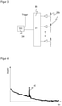
- FIG 1 shows a simplified schematic block diagram of an optoelectronic sensor 10 in an embodiment as a light sensor.
- a light emitter 12 for example an LED or a laser light source in the form of an edge emitter or a VCSEL, emits a light pulse 16 through a transmission optics 14 into a monitoring area 18.
- the light transmitter 12 and the transmission optics 14 produce a round or an elongated beam cross-section, with the longitudinal direction preferably being perpendicular to the plane of the paper in the case of an elongated beam cross-section.
- the light receiver 26 has a plurality of light receiving elements 26a arranged in a row, X denoting the direction along the row.
- the linear light receiver 26 can be aligned in particular in the Scheimpflug arrangement.
- Each light-receiving element 26a in turn comprises at least one avalanche photodiode element (SPAD, Single Photon Avalanche Diode) operated in the Geiger mode.
- SPAD avalanche photodiode element
- the received signals from the light receiving elements 26a or from their avalanche photodiode elements are read out by a control and evaluation unit 28 and evaluated there in order to measure the distance D from the object 20 .
- the control and evaluation unit 28 uses a time-of-flight method, in which the time-of-flight from the emission of the light pulse 16 to the receipt of the reflected light pulse 22 is determined and, if necessary, converted to the distance D via the speed of light.
- the point of impact of the remitted light pulse 22 or of the received light spot generated thereby on the linear light receiver 26 and from this the distance D is determined once more by means of triangulation.
- the two distance measurements using time-of-flight measurement and triangulation measurement will be explained in more detail later with reference to the other figures.
- both distances determined by means of time-of-flight methods and triangulation methods a resulting distance calculated therefrom or only a binary switching signal depending on the presence or absence of the object 20 in a specific distance range are output at an output 30.
- the senor 10 has further elements which, for the sake of simplicity, are not described further here, such as further interfaces for parameterization and the like.
- the separation into light receiver 26 and control and evaluation unit 28 in figure 1 is also conceivable in practice, but primarily serves as an explanation.
- These elements are preferably at least partially integrated on a common chip, the area of which is shared by light-sensitive areas of the avalanche photodiode elements and circuits assigned to individual circuits or groups of avalanche photodiode elements for evaluating and controlling them. All of the components can be accommodated in a compact manner in a sensor 10 and in particular in a housing which is closed off by a front pane 32 in the passage area of the light pulses 16 , 22 . In figure 1 If the outer surface of the front pane 32 is the reference point for the measured distance D, another zero point can of course also be defined here by appropriate conversion.
- figure 1 The basic structure according to figure 1 is only to be understood schematically and as an example. There are also other embodiments of optoelectronic sensors according to the invention, in particular each of triangulation sensors or background suppression Light sensors can correspond to a known structure. Also conceivable are laser scanners in which an optical measuring head is figure 1 is rotated or pivoted.
- FIG. 1 shows further details of the light receiver 26 and the evaluation unit 28.
- the linear light receiver 26 has the light receiving elements 26a as pixels.
- the light receiving elements 26a themselves comprise sub-pixels, namely a column of a plurality of Geiger mode avalanche photodiode elements 26b in an arrangement perpendicular to the row direction.
- the avalanche photodiode elements 26b are arranged differently within the light receiving element 26a or have different areas. Embodiments with only one avalanche photodiode element 26b per light receiving element 26a are also possible.
- the avalanche photodiode elements 26b can preferably be switched off individually, particularly simply by lowering the bias voltage below the breakdown voltage.
- the avalanche photodiode elements 26b of a light receiving element 26a are each connected to a TDC 34 (time-to-digital converter), with the TDCs 34 functioning as time-of-flight measuring units.
- An avalanche event in an avalanche photodiode element 26b stops the TDC 34. This measures the time from a predetermined trigger, for example the transmission time of the light pulse 16.
- the avalanche photodiode elements 26b start the TDC 34, which stops again with a predetermined trigger. Constant times can then be subtracted out to relate D to a specific location such as windshield 32.
- FIG 3 shows the connection to a TDC 34 for the avalanche photodiode elements 26b of an individual light receiving element 26a in more detail.
- this is an OR link, with the result that the first event in one of the assigned avalanche photodiode elements 26b then triggers the TDC.
- Other combining logics 36 require that at least m out of n avalanche photodiode elements 26b trigger, or that they trigger together with a combining logic 36 designed as a coincidence detector within a specific narrow time window.
- a bias voltage above the breakdown voltage is advantageously applied only during the active phases.
- This process known as gating, has the advantage that the avalanche photodiode elements 26b can only trigger in the relevant measurement time window, so that the probability of triggering is greatly reduced by background light and the avalanche photodiode elements 26b are not already in their dead time at the beginning of the measurement. In addition to the improved background stability, this also reduces power consumption.
- TDC 34 As an alternative to an assignment of one TDC 34 per light receiving element 26a, several TDCs 34 up to one TDC 34 per avalanche photodiode element 26b are also conceivable. This increases the circuit complexity, but also results in more measurement events. Conversely, there can also be fewer TDCs 34, with a loss of resolution, with the selection of an interesting partial area of the line arrangement, or by sequential evaluation or multiplexing.
- the individual light travel times determined by the TDC 34 are collected in a histogram 38 which divides the relevant distance range into bins and counts the frequency of the individual light travel times falling into each bin.
- Several individual measured light propagation times result from measurement repetition, ie the transmission and reception of further light pulses 16, 22 and/or from the fact that in deviation from the one-to-one assignment of figure 2 several TDCs 34 together a histogram 38, in particular different than in figure 3 multiple TDCs 34 are associated with the avalanche photodiode elements 26b of the same light receiving element 26a.
- the histogram 38 occupies, for example, a RAM area with one memory location per bin of the histogram.
- the histograms 38 are then read out and processed in a further evaluation 40 .
- the light-receiving elements 26a, the TDCs 34 and the memory areas of the histograms 38 are accommodated on a shared ASIC, while the further evaluation 40 is carried out by a microprocessor.
- the further evaluation 40 is carried out by a microprocessor.
- an implementation on more or less and also other evaluation modules is also conceivable.
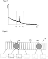
- figure 4 shows an example histogram.
- the bins are plotted on the x-axis, which corresponds to a discretization of the time axis. Individually measured light propagation times per bin are counted on the Y-axis. Each event counted in the histogram is a single time-of-flight measured by a TDC 34. This should not be confused with the time-of-flight, which is measured in total by the sensor 10 to determine the distance D and which is sought as a result of the histogram evaluation.
- the histogram shows the underlying, exponentially decreasing background typical of SPADs, which is also inherently noisy. This behavior results from the dead times: If a SPAD is triggered, whether by a dark event, by background light or by useful light of the remitted light pulse 22, then it is no longer available for further individual measurements (pile-up effect).
- the measurement result sought is the local maximum 42, also referred to as an echo peak, where the individual light propagation times measured from the useful light accumulate. Behind the local maximum 42 there is a jump in the falling exponential function because a larger subpopulation of the SPADs is put into the dead time by the echo peak.
- the local maximum 42 turns out to be smaller than the background at the beginning of the individual measurement, because when the remitted light pulse 22 arrives with a stronger background load, not all avalanche photodiode elements 26b are available for a long time.
- the further evaluation 40 can gather two important pieces of measurement information from the histogram and its local maximum 42: the light propagation time can be determined from its position, and its area is a measure of the reception level, which in turn can be used for the triangulation.
- FIG. 1 shows again the line arrangement of the light receiving elements 26a of the light receiver 26a, the individual avalanche photodiode elements 26b being omitted for the sake of simplicity.
- a histogram as in figure 4 generated and evaluated per light receiving element 26a. This is shown below the light receiver for some of the light receiving elements 26a.
- X continues to indicate the direction along the line array, and the histograms are numbered accordingly. This number or identity of the respective histogram thus contains the geometric information or spatial resolution where along the line arrangement the histogram was recorded.
- each of the histograms provides information about the location of the received light spot 44, which the reflected light pulse 22 generates on the light receiver 26.
- the received light spot 44 is located where a local maximum 42 can be found in the histograms.
- the location of the local maximum 42 from each histogram, the distance value D can be estimated, and the number of events contributing to the local maximum 42, i.e. the area of the local maximum 42, is a measure of the reception level or the intensity of the reception light spot 44 at the location on the line arrangement , which corresponds to the histogram.
- each histogram contains background information.
- the histograms 10 to 12 are those that contain useful light information of the received light spot 44 .
- the remaining histograms only show background light and can be ignored except to estimate it.
- Each of the histograms 10 to 12 enables a robust time-of-flight measurement via the position of the local maximum 42, with the respective estimates for D being able to be averaged, for example, in particular averaged with the reception level determined in each case. It is also possible to combine the individual events into a common histogram and evaluate this.
- the identity of the histograms is information about the point of impact of the received light spot 44, which can be used as a basis for triangulation. So far this is still a very rough triangulation, which later with reference to the Figures 10 to 13 is clearly refined, but the principle is already understandable here.
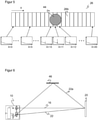
- figure 6 shows a conventionally problematic case of multiple propagation of the light pulse 16, 22 or mirror reflection. Not only does a remitted light pulse 22 return directly, but another light pulse 22a takes a detour via a mirror 46.
- the mirror 46 can also be a shiny surface made of metal, for example, which in industrial environments of the sensor 10 often occurs.
- a number of received light spots are formed on the light receiver 26 as a result of reflection, and the correct distance D is measured neither with the time of flight of the light nor with triangulation alone. Due to the distance measurement according to the invention both by means of light propagation time as well as triangulation, implausible received light spots can be sorted out. Similar effects as by reflection in figure 6 occur with shiny or reflective surfaces of the object 20.
- the areas of the histogram outside the permissible range, ie individual light propagation times corresponding to D ⁇ D 0 or D>D 1 are ignored in the calculation of the distance value to the object 20 or in the presence detection for the output of a switching signal.
- figure 8 shows a different view of the mutual plausibility check, which can also be used in addition. It is not parts of a histogram that are ignored, but entire histograms. How to figure 6 explained, there can be multiple received light spots 44a-b due to multipath propagation. According to the geometric laws of triangulation, the received light spot 44b is apparently in the close range, but at the same time the light propagation time is very clearly in the far range, since the light pulse 22a has traveled the detour via the mirror 46 . This does not match, this received light spot 44b and the associated histograms are ignored. Therefore the corresponding histograms as well as those containing only background are in figure 8 greyed out.
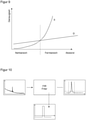
- figure 9 shows a schematic comparison of the resolution or accuracy of the distance measurement using the time-of-flight method (D) and using triangulation (X). The exact course depends on many parameters, but the basic behavior is off figure 9 readable.
- the change in impact location is inversely proportional to the square of the distance to the object.
- the change is therefore large for close objects and quickly approaches zero for larger distances.
- triangulation is accurate at close range, but not at long range.
- the corresponding change in the time of flight of light remains proportional to the change in distance for any distance.
- the accuracy is limited to several millimeters to centimeters, so that measurement of the time of flight at close range does not achieve the precision of triangulation.
- both pieces of distance information are available, and the more precise one can be used in each case, ie the triangulation in the close range and the light propagation time in the far range.
- figure 9 there is a sharp boundary between the near and far range. This point may actually be fixed for a particular sensor 10, but it is also conceivable to create a smoother transition by averaging both distance information appropriately weighted with the distance.
- SPADs Due to the special nature of SPADs, special additional measures should preferably be observed during the triangulation measurement. When overdriven, SPADs show a strong compression effect, and its negative effect on the triangulation measurement should be compensated for.
- figure 10 12 shows another histogram on the left, the reception level information required for the triangulation being in the area of the local maximum 42 or at its height.
- a way to estimate the intensity of the local maximum 42 uses a convolution with an FIR filter to remove the background light generated signal portion from the histogram.
- the position of the rising flank of the local maximum 42 and its height L(x) are determined via a threshold value and the window delimited by D 0 and D 1 already discussed.
- the local maximum 42 is integrated in the window.
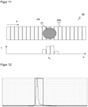
- figure 11 shows once again the line arrangement of the light receiver 26 and below it the corresponding local distribution L(X) of the reception level.
- the reception level from histograms on light receiving elements 26a reaching only back light is set to zero.
- L(X) is consequently the intensity distribution, and from this, as is conventional, the position X 0 of the received light spot 44 can be determined with sub-pixel accuracy, for example as the center of gravity or median.
- figure 12 shows again the intensity distribution as in the lower part of the figure 11 , only with more pixels or light-receiving elements 26a in the X-direction along the line arrangement, namely now 128.
- a conventional triangulation sensor with PN or PIN photodiodes there is a linear relationship between the irradiance and the output signal. For this reason, a graded intensity distribution also arises, which enables an exact determination of X 0 .
- the signal drawn with a thick line corresponds to a situation in which the triggering probability of the SPADs in the line arrangement of the light receiver 26 is close to one hundred percent and they accordingly go into saturation or deliver full deflection. But that happens relatively easily with SPADs. It is clear that a subpixel- precise determination of X 0 is no longer conceivable. SPADs do not show the simple linear relationship. As the background light increases, fewer and fewer SPADs are available (pile-up effect), and it happens relatively quickly that the probability of triggering becomes too great and this leads to the unfavorable situation of full deflection.
- the sensitivity should be set appropriately so that the probability of triggering remains noticeably less than one.
- the transmission power of the light transmitter 12 and/or the sensitivity of the light receiving elements 26a can be changed for this. This is possible on the one hand by adjusting the preload.
- a plurality of avalanche photodiode elements 26b of different sizes can be used in one light receiving element 26a. By selecting active avalanche photodiode elements 26b in each case, the probability of detection when useful light is received is then also varied.
- figure 13 shows a purely schematic flow chart for a triangulation.
- the variable L(x), ie the intensity distribution in the received light spot 44 depends not only on the optical received power P rec (x) but also on the background light, the distance to the object and the remission of the object.
- the background light can be estimated from histograms or histogram areas with no useful light, ie outside the local maximum 42 .
- the distance is known from the time-of-flight measurement. Knowing the background and distance, the reflectance can be estimated from the reception level, since it is possible to calculate which reception level would be expected given a reference reflectance of, for example, one hundred percent.
Landscapes
- Engineering & Computer Science (AREA)
- Physics & Mathematics (AREA)
- Computer Networks & Wireless Communication (AREA)
- General Physics & Mathematics (AREA)
- Radar, Positioning & Navigation (AREA)
- Remote Sensing (AREA)
- Electromagnetism (AREA)
- Optical Radar Systems And Details Thereof (AREA)
- Measurement Of Optical Distance (AREA)
Description
Die Erfindung betrifft einen optoelektronischen Sensor und ein Verfahren zur Erfassung eines Objekts in einem Überwachungsbereich nach dem Oberbegriff von Anspruch 1 beziehungsweise 13.The invention relates to an optoelectronic sensor and a method for detecting an object in a monitored area according to the preamble of claim 1 and 13, respectively.
Es gibt verschiedene Messprinzipien, um mit einem optoelektronischen Sensor den Abstand zu einem erfassten Objekt zu bestimmen. Lichtlaufzeitverfahren bestimmen die Laufzeit eines Lichtsignals, die über die Lichtgeschwindigkeit dem gesuchten Abstand entspricht. In einem Pulslaufzeitverfahren wird ein kurzer Lichtpuls ausgesandt und die Zeit bis zum Empfang einer Remission oder Reflexion des Lichtpulses gemessen. Alternativ wird bei einem Phasenverfahren Sendelicht amplitudenmoduliert und eine Phasenverschiebung zwischen Sende- und Empfangslicht bestimmt, wobei die Phasenverschiebung ebenfalls ein Maß für die Lichtlaufzeit ist. Da die Lichtlaufzeiten extrem kurz sind, ist eine Abstandsauflösung im Bereich von Zentimetern oder gar Millimetern bereits eine große Herausforderung, und feinere Auflösungen sind zumindest bislang technisch kaum erreichbar. Dafür sind mit weitgehend gleicher Genauigkeit auch große Reichweiten möglich.There are different measuring principles to determine the distance to a detected object with an optoelectronic sensor. Time-of-flight methods determine the run-time of a light signal, which corresponds to the distance sought via the speed of light. In a pulse propagation time method, a short light pulse is emitted and the time until reception of a remission or reflection of the light pulse is measured. Alternatively, in a phase method, the transmitted light is amplitude-modulated and a phase shift between the transmitted and received light is determined, the phase shift also being a measure of the light propagation time. Since the light propagation times are extremely short, a distance resolution in the range of centimeters or even millimeters is already a major challenge, and finer resolutions have hardly been achievable, at least not technically. Large ranges are also possible with largely the same accuracy.
Bei einem Triangulationsverfahren liegen Lichtsender und Lichtempfänger in einem Basisabstand nebeneinander. Je nach Abstand des Objekts, welches das ausgesandte Licht zurückwirft, wird das Empfangslicht an einer anderen Position auf einem ortsaufgelösten Lichtempfänger registriert und der Auftreffort in den Abstand umgerechnet. Triangulation ist für große Abstände weniger geeignet, dafür im Nahbereich extrem präzise bis in den Mikrometerbereich. Die erzielbare Reichweite hängt natürlich vom konkreten Sensor und Parametern wie Sendeleistung auch unter Berücksichtigung von Augenschutz, Baugröße und damit Größe der Empfangslinse sowie dem Basisabstand ab, ist aber jedenfalls gegenüber Lichtlaufzeitverfahren deutlich beschränkt. Da weiterhin im Kern die Position eines Lichtflecks auf dem ortsaufgelösten Lichtempfänger gemessen wird, gibt es Störeinflüsse durch nicht ideale Randbedingungen, etwa spiegelnde oder glänzende Objekte sowie spiegelnde oder glänzende Umgebungen.In a triangulation method, the light transmitter and light receiver are next to one another at a base distance. Depending on the distance of the object that reflects the emitted light, the received light is registered at a different position on a spatially resolved light receiver and the point of impact is converted into the distance. Triangulation is less suitable for large distances, but is extremely precise at close range, down to the micrometer range. Of course, the achievable range depends on the specific sensor and parameters such as transmission power, also taking into account eye protection, size and thus size of the receiving lens and the base distance, but is clearly limited compared to time-of-flight methods. Furthermore, the position of a light spot on the spatially resolved light receiver is measured in the core there are interferences caused by non-ideal boundary conditions, such as reflective or shiny objects and reflective or shiny environments.
Der gemessene Abstand kann unmittelbar die Ausgabegröße des Sensors sein. Es gibt aber auch schaltende Systeme, die ein Objekt nur dann erfassen, wenn es sich in einem bestimmten Abstandsbereich befindet. Dazu zählen hintergrundausblendende Lichttaster, die Objekte ab einer bestimmten Entfernung ignorieren, und Lichtschranken, die den Abstand zum zugeordneten Reflektor überwachen.The measured distance can directly be the output of the sensor. However, there are also switching systems that only detect an object when it is within a certain distance. These include background-suppressing light sensors that ignore objects from a certain distance, and light barriers that monitor the distance to the assigned reflector.
Die Anforderungen an einen entfernungsmessenden optoelektronischen Sensor können sich je nach Anwendung und Umgebungsbedingungen erheblich unterscheiden. Der abzudeckende Dynamikbereich umfasst nahe und ferne Objekte, zudem unterschiedliche Remissionen etwa von glänzenden Flächen bis hinunter zu beispielsweise schwarzem Samt. Daher sind besonders geeignete Lichtempfänger Lawinenphotodioden, die im sogenannten Geiger-Modus betrieben werden (SPAD, Single Photon Avalanche Diode).The requirements for a distance-measuring photoelectric sensor can vary significantly depending on the application and environmental conditions. The dynamic range to be covered includes near and distant objects, as well as different remissions, for example from shiny surfaces down to black velvet, for example. Therefore, particularly suitable light receivers are avalanche photodiodes, which are operated in the so-called Geiger mode (SPAD, Single Photon Avalanche Diode).
In einer SPAD wird eine Vorspannung oberhalb der Durchbruchspannung angelegt, und dann genügt bereits ein einziger, durch ein einzelnes Photon freigesetzter Ladungsträger zum Auslösen einer nicht mehr kontrollierten Lawine, die dann aufgrund der hohen Feldstärke sämtliche verfügbaren Ladungsträger rekrutiert. Danach kommt die Lawine zum Erliegen (passive quenching) und steht für eine gewisse Totzeit nicht mehr zur Detektion zur Verfügung. Alternativ ist auch bekannt, die Lawine von außen zu erkennen und zu löschen (active quenching). Eine Besonderheit von SPADs ist die Tatsache, dass auch ein minimales Störereignis, wie ein Fremdlichtphoton oder Dunkelrauschen, das gleiche maximale Empfangssignal erzeugt wie ein Nutzlichtsignal. Um diese Auswirkungen zu begrenzen, werden in der Praxis mehrere SPADs gemeinsam ausgewertet. Bezüglich dieser und weiterer allgemeiner Eigenschaften von SPADs sei beispielhaft auf den Artikel
In dem Artikel
Die
Die
Die
In der
Die
In der
Aus der
Die
Es ist daher Aufgabe der Erfindung, einen optoelektronischen Sensor mit Abstandsmessung nach dem Lichtlaufzeitverfahren weiter zu verbessern.It is therefore the object of the invention to further improve an optoelectronic sensor with distance measurement using the time-of-flight method.
Diese Aufgabe wird durch einen optoelektronischen Sensor und ein Verfahren zur Erfassung eines Objekts in einem Überwachungsbereich nach Anspruch 1 beziehungsweise 13 gelöst. Ein Lichtsender sendet einen Lichtpuls in den Überwachungsbereich aus, der von dem angetasteten Objekt zumindest teilweise zurückgeworfen wird und dann als remittierter Lichtpuls einen Empfangslichtfleck auf einem Lichtempfänger erzeugt. Als Lichtempfänger ist eine Zeilenanordnung von Lichtempfangselementen oder eine Pixelzeile eingesetzt. Jedes Lichtempfangselement oder Pixel wiederum weist eine oder mehrere Lawinenphotodiodenelemente auf, die jeweils mit einer Vorspannung oberhalb einer Durchbruchspannung vorspannbar und somit in einem Geiger-Modus betreibbar sind, oder anders ausgedrückt eine oder mehrere SPADs. Mehrere Lawinenphotodiodenelemente bilden vorzugsweise eine Spalte senkrecht zu der Zeilenanordnung. Eine Auswertungseinheit misst die Lichtlaufzeit mit Hilfe der Empfangssignale der Lawinenphotodiodenelemente und bestimmt daraus über die konstante Lichtgeschwindigkeit den Abstand zu dem Objekt.This object is achieved by an optoelectronic sensor and a method for detecting an object in a surveillance area according to claims 1 and 13, respectively. A light transmitter emits a light pulse into the monitoring area, which is at least partially reflected by the object touched and then generates a received light spot on a light receiver as a remitted light pulse. A line arrangement of light receiving elements or a pixel line is used as the light receiver. Each light receiving element or pixel in turn comprises one or more avalanche photodiode elements each of which can be biased above a breakdown voltage and thus operable in a Geiger mode, or in other words one or more SPADs. A plurality of avalanche photodiode elements preferably form a column perpendicular to the row arrangement. An evaluation unit measures the light propagation time using the received signals from the avalanche photodiode elements and uses the constant speed of light to determine the distance to the object.
Die Erfindung geht von dem Grundgedanken aus, zusätzlich zu der ersten Abstandsmessung mittels Lichtlaufzeitverfahren eine zweite Abstandsmessung mittels Triangulationsverfahren durchzuführen. Dazu wird der Auftreffort des remittierten Lichtpulses beziehungsweise die Lage des Empfangslichtflecks auf der Zeilenanordnung bestimmt und der gesuchte Abstand anhand der bekannten Sensorparameter berechnet, insbesondere dem Basisabstand zwischen Lichtsender und Lichtempfänger beziehungsweise deren Optiken.The invention is based on the basic idea of carrying out a second distance measurement using a triangulation method in addition to the first distance measurement using the time-of-flight method. For this purpose, the point of impact of the reflected light pulse or the position of the received light spot on the line arrangement is determined and the distance sought is calculated using the known sensor parameters, in particular the basic distance between the light transmitter and light receiver or their optics.
Es sind verschiedene Sensortypen denkbar, wie in der Einleitung angeführt, welche auch die beiden Abstandsmessungen auf unterschiedliche Weise nutzen. Ein entfernungsmessender Lichttaster gibt beide Abstandswerte aus oder verrechnet sie zuvor zu einem gemeinsamen Abstandswert. Eine abstandsüberwachende Lichtschranke oder ein hintergrundausblendender Lichttaster erzeugt nach außen nur ein Schaltsignal je nach Anwesenheit des Objekts in einem bestimmten Abstandsbereich.Various sensor types are conceivable, as mentioned in the introduction, which also use the two distance measurements in different ways. A distance-measuring light scanner outputs both distance values or calculates them beforehand to form a common distance value. A distance-monitoring light barrier or a background-suppressing light scanner only generates a switching signal depending on the presence of the object within a certain distance range.
Die Erfindung hat den Vorteil, dass durch Kombination der beiden Entfernungsmessungen die Zuverlässigkeit und Robustheit der Entfernungsmessung und Anwesenheitserkennung verbessert wird. Das funktioniert auch mit den besonderen Signalen von SPADs, so dass deren Vorteile verwirklicht sind: hohe Empfindlichkeit mit Verstärkungsfaktoren bis zu 108 sowie hohe Integrierbarkeit und geringe Kosten.The invention has the advantage that the combination of the two distance measurements improves the reliability and robustness of the distance measurement and presence detection. This also works with the special signals of SPADs, so that their advantages are realised: high sensitivity with amplification factors of up to 10 8 as well as high integrability and low costs.
Die Steuer- und Auswertungseinheit ist bevorzugt dafür ausgebildet, Lichtlaufzeiten mehrfach durch Messwiederholung und/oder getrennte Auswertung der Empfangssignale zu messen. Messwiederholung bedeutet, dass ein weiterer Lichtpuls ausgesandt und wieder empfangen wird. Eine Mehrfachmessung entsteht alternativ oder zusätzlich durch Empfang eines remittierten Lichtpulses in mehreren Lawinenphotodiodenelementen und Mehrfachauswertung der Empfangssignale von einzelnen Lawinenphotodiodenelementen oder mehreren Gruppen davon. Auch ganz allgemein erhöht sich die Messgenauigkeit durch Mehrfachmessung, aber bei Lawinenphotodiodenelementen im Geiger-Modus ist das besonders vorteilhaft, weil Einzelmessungen auf ein Dunkel- oder Fremdlichtereignis zurückgehen können und damit nicht nur um eine gewisse Rauschtoleranz wie bei anderen Lichtempfangselementen abweichen, sondern gar nicht der gewünschten Lichtlaufzeit entsprechen.The control and evaluation unit is preferably designed to measure light propagation times multiple times by repeating measurements and/or separate evaluation of the received signals. Measurement repetition means that another light pulse is sent out and received again. Alternatively or additionally, a multiple measurement results from receiving a remitted light pulse in a plurality of avalanche photodiode elements and multiple evaluation of the received signals from individual avalanche photodiode elements or a plurality of groups thereof. Also, in general, the measurement accuracy increases through multiple measurements, but this is particularly advantageous with avalanche photodiode elements in Geiger mode, because individual measurements can be traced back to a dark or extraneous light event and thus not only deviate by a certain noise tolerance as with other light-receiving elements, but not at all correspond to the desired light transit time.
Die Steuer- und Auswertungseinheit weist bevorzugt eine Vielzahl von Lichtlaufzeitmesseinheiten auf, die jeweils einem oder mehreren Lawinenphotodiodenelementen zugeordnet sind. Vorzugsweise ist jeweils eine Lichtlaufzeitmesseinheit je Lichtempfangselement vorgesehen. Sind mehrere Lawinenphotodiodenelemente derselben Lichtlaufzeitmesseinheit zugeordnet, so wird vorteilhafterweise eine zusammenfassende Logik dazwischengeschaltet, beispielsweise eine ODER-Logik, eine Summation oder eine Koinzidenzlogik, die zum Ausfiltern von vereinzelten Störereignissen nur dann reagiert, wenn eine Mindestanzahl Ereignisse in einem sehr engen Zeitfenster auftritt. Die Zuordnung der Lichtlaufzeitmesseinheiten kann fix oder variabel sein. Im letzteren Fall wird beispielsweise ein bestimmter interessierender Bereich der Zeilen-anordnung ausgesucht, dessen Lawinenphotodiodenelemente mit einer Lichtlaufzeitmesseinheit verbunden wird, oder die Lawinenphotodiodenelemente werden mittels Multiplexing zeitversetzt auswertet.The control and evaluation unit preferably has a large number of time-of-flight measuring units, each of which is assigned to one or more avalanche photodiode elements. Preferably, a time-of-flight measuring unit is provided for each light-receiving element. If several avalanche photodiode elements are assigned to the same time-of-flight measurement unit, a summarizing logic is advantageously interposed, for example OR logic, summation or coincidence logic, which only reacts to filter out isolated disruptive events if a minimum number of events occurs in a very narrow time window. The assignment of the time-of-flight measurement units can be fixed or variable. In the latter case, for example, a certain interesting area of the line arrangement is selected, whose avalanche photodiode elements are connected to a time-of-flight measurement unit, or the avalanche photodiode elements are evaluated with a time delay using multiplexing.
Die Lichtlaufzeitmesseinheiten weisen bevorzugt einen TDC (Time-to-Digital Converter) auf. Das sind bewährte Bauteile, um Zeitmessungen durchzuführen und die praktisch als Stoppuhren arbeiten, die durch einen gemeinsamen Zeitbezug wie dem Sendezeitpunkt des Lichtpulses ausgelöst und durch die SPADs angehalten werden, oder umgekehrt durch die SPADs ausgelöst und einen festgelegten gemeinsamen Zeitbezug angehalten werden. Vorzugsweise sind die TDCs direkt bei den Pixeln oder Lichtempfangselementen oder zumindest auf demselben Chip implementiert.The time-of-flight measuring units preferably have a TDC (time-to-digital converter). These are tried-and-tested components for carrying out time measurements and which practically work as stopwatches, which are triggered by a common time reference such as the transmission time of the light pulse and stopped by the SPADs, or conversely triggered by the SPADs and a fixed common time reference is stopped. Preferably, the TDCs are implemented directly at the pixels or light receiving elements, or at least on the same chip.
Die Steuer- und Auswertungseinheit ist dafür ausgebildet, eine Vielzahl von gemessenen Lichtlaufzeiten in einem Histogramm zu akkumulieren, in dessen Bins gezählt wird, wie oft eine Lichtlaufzeit in einem bestimmten Lichtlaufzeitbereich gemessen wurde. Das Histogramm unterteilt den interessierenden Lichtlaufzeitbereich von Null bis zur maximalen Reichweite oder einen Teilbereich davon in vorzugsweise gleichmäßige Bins und zählt, wie oft eine jeweils in das Bin fallende Lichtlaufzeit gemessen wurde. Die Breite der Bins wird unter anderem anhand der gewünschten zeitlichen Auflösung und des vorhandenen Speichers gewählt. Die Vielzahl von Lichtlaufzeiten entsteht in der Zeit durch Messwiederholung mit jeweils einem weiteren ausgesandten Lichtpuls und/oder im Raum durch die Mehrfachauswertung unterschiedlicher Lawinenphotodiodenelementen beziehungsweise Gruppen davon. Mit einem Histogramm sind statistische Auswertungen der Mehrfachmessung zur Bestimmung einer genaueren Lichtlaufzeit einfach möglich.The control and evaluation unit is designed to accumulate a large number of measured light propagation times in a histogram, in whose bins it is counted how often a light propagation time was measured in a specific light propagation time range. The histogram divides the time-of-flight range of interest from zero to the maximum range or a sub-range thereof into preferably uniform bins and counts how often a time-of-flight falling into the bin was measured. The width of the bins is selected on the basis of the desired time resolution and the available memory, among other things. The multiplicity of light propagation times arises over time through measurement repetitions each with a further emitted light pulse and/or in space through the multiple evaluation of different avalanche photodiode elements or groups thereof. With a histogram, statistical evaluations of the multiple measurement to determine a more accurate light propagation time are easily possible.
Die Steuer- und Auswertungseinheit ist dafür ausgebildet, jeweils ein Histogramm für einen jeweiligen Bereich der Zeilenanordnung zu akkumulieren, insbesondere ein Histogramm je Lichtempfangselement. Damit steht eine über die Zeile ortsaufgelöste Information zur Verfügung. Diese Ortsauflösung wird im Weiteren genutzt, um die Lichtlaufzeitmessung mit geometrischen Informationen nach dem Prinzip der Triangulation zu plausibilisieren und genauer zu machen.The control and evaluation unit is designed to accumulate a histogram for a respective area of the line arrangement, in particular a histogram for each light-receiving element. This provides spatially resolved information about the line. This spatial resolution is then used to check the plausibility of the time-of-flight measurement with geometric information according to the principle of triangulation and to make it more precise.
Die Steuer- und Auswertungseinheit ist bevorzugt dafür ausgebildet, in jedem Histogramm einen Abstandswert aus der Position des durch den remittierten Lichtpuls erzeugten lokalen Maximums zu bestimmen. Da mehrere Histogramme bereitstehen, kann die Lichtlaufzeit auch mehrfach redundant aus jedem dieser Histogramme gemessen werden, insbesondere einmal pro Lichtempfangselement. Ein lokales Maximum in einem Histogramm entsteht aus einer Häufung von einzelnen gemessenen Lichtlaufzeiten. Solche Häufungen gibt es in den Histogrammen, die Lichtempfangselementen zugeordnet sind, auf die tatsächlich der Empfangslichtfleck des remittierten Lichtpulses fällt. Innerhalb dieser Histogramme liegt das lokale Maximum bei Lichtlaufzeiten, die dem Abstand zu dem angetasteten Objekt entsprechen. Andere Lichtlaufzeiten werden aufgrund von Rauscheffekten gemessen, also Dunkel- oder Fremdlichtereignissen. Bei SPADs ergibt sich ein besonderes Hintergrund- oder Rauschverhalten mit exponentiellem Abfall. Das liegt daran, dass eine SPAD, in der eine Lawine ausgelöst wurde, für die übrige Messung wegen ihrer Totzeit nicht mehr verfügbar ist. Daher erzeugt der remittierte Lichtpuls nicht unbedingt ein globales, sondern nur ein lokales Maximum, denn gerade ein fernes Objekt erzeugt möglicherweise weniger Ereignisse als das Hintergrundlicht kurz nach Aussenden des Lichtpulses, wenn noch alle SPADs verfügbar sind. Das lokale Maximum wird auch Echopeak genannt.The control and evaluation unit is preferably designed to determine a distance value from the position of the local maximum generated by the reflected light pulse in each histogram. Since several histograms are available, the light propagation time can also be measured multiple times from each of these histograms, in particular once per light-receiving element. A local maximum in a histogram arises from an accumulation of individually measured light propagation times. There are such accumulations in the histograms that are assigned to light receiving elements on which the received light spot of the remitted light pulse actually falls. Within these histograms, the local maximum is at the light propagation times that correspond to the distance to the object touched. Other light propagation times are measured due to noise effects, i.e. dark or extraneous light events. With SPADs, there is a special background or noise behavior with exponential decay. This is because a SPAD in which an avalanche has been triggered is no longer available for the rest of the measurement due to its dead time. Therefore, the reflected light pulse does not necessarily generate a global but only a local maximum, since a distant object may generate fewer events than the background light shortly after the light pulse has been emitted, when all SPADs are still available. The local maximum is also called the echo peak.
Die Steuer- und Auswertungseinheit ist bevorzugt dafür ausgebildet, gemessene Lichtlaufzeiten aus Histogrammen beziehungsweise die Histogramme oder die daraus gewonnenen Informationen zu ignorieren, in denen kein lokales Maximum identifiziert werden kann. Es wird davon ausgegangen, dass in solchen Histogrammen nur Dunkel- und Hintergrundereignisse registriert wurden. Sie liegen außerhalb des Bereichs des Empfangslichtflecks auf der Zeilenanordnung, enthalten also gar keine Nutzlichtinformation und können weder zur Lichtlaufzeitmessung noch zur Triangulationsmessung sinnvoll beitragen.The control and evaluation unit is preferably designed to ignore measured light propagation times from histograms or the histograms or the information obtained from them, in which no local maximum can be identified. It is assumed that only dark and background events were registered in such histograms. They lie outside the area of the received light spot on the line arrangement, so they contain no useful light information at all and can make a meaningful contribution neither to the time-of-flight measurement nor to the triangulation measurement.
Die Steuer- und Auswertungseinheit ist dafür ausgebildet, einen Empfangspegel je Histogramm zu bestimmen, insbesondere durch Integrieren des durch den remittierten Lichtpuls erzeugten lokalen Maximums oder durch dessen Höhe. Die Integration in einem Histogramm erfolgt in der Praxis diskret durch Aufaddieren der entsprechenden Bins. Über die so bestimmte Fläche des lokalen Maximums wird ermittelt, wie viele Nutzlichtereignisse zu dem lokalen Maximum beitragen, und das ist ein Maß für den Empfangspegel. Ein anderes einfaches Maß ist die Höhe des lokalen Maximums. Dabei wird vorzugsweise das Hintergrundlicht kompensiert. Gibt es kein lokales Maximum, dann handelt es sich um ein Histogramm, das nach dem Vorabsatz dem Hintergrund zuzurechnen ist, der Empfangspegel des Nutzlichts ist hier Null.The control and evaluation unit is designed to determine a reception level for each histogram, in particular by integrating the local maximum generated by the reflected light pulse or by its level. In practice, the integration in a histogram occurs discretely by adding up the corresponding bins. The area of the local maximum determined in this way is used to determine how many useful light events contribute to the local maximum, and this is a measure of the reception level. Another simple measure is the height of the local maximum. In this case, the background light is preferably compensated for. If there is no local maximum, then it is a histogram which, according to the preamble, is to be attributed to the background; the reception level of the useful light is zero here.
Die Steuer- und Auswertungseinheit ist dafür ausgebildet, den Auftreffort aus der Verteilung der Empfangspegel über die Histogramme zu bestimmen. Es wird also aus jedem Histogramm bestimmt, beispielsweise wie im vorigen Absatz beschrieben, wie stark der remittierte Lichtpuls in den zugeordneten Lawinenphotodiodenelementen registriert wurde, beispielsweise wie hoch der Echopeak ist oder welche Fläche er einnimmt. Das ergibt eine Ortsverteilung der Intensität des Empfangslichtflecks, aus der sich der Auftreffort beispielsweise als Schwerpunkt oder Median bestimmen lässt.The control and evaluation unit is designed to determine the point of impact from the distribution of the reception level over the histograms. It is thus determined from each histogram, for example as described in the previous paragraph, how strong the remitted light pulse was registered in the associated avalanche photodiode elements, for example how high the echo peak is or what area it occupies. This results in a spatial distribution of the intensity of the received light spot, from which the point of impact can be determined, for example as the center of gravity or median.
Die Steuer- und Auswertungseinheit ist bevorzugt dafür ausgebildet, die Auslösewahrscheinlichkeit der Lawinenphotodiodenelemente bei Empfang des remittierten Lichtpulses unterhalb einer Sättigung zu halten, insbesondere durch Anpassung der Sendeleistung des Lichtsenders oder der Empfindlichkeit der Lawinenphotodiodenelemente. Bei den hochempfindlichen SPADs kann es leicht geschehen, dass sämtliche von Nutzlicht getroffenen SPADs auslösen. Damit sind aber die Histogramme im Bereich des Empfangslichtflecks im Vollausschlag, eine Feinauswertung der Intensitätsverteilung ist nicht mehr möglich. Deshalb wird vorzugsweise dafür gesorgt, dass auch ein von dem remittierten Lichtpuls getroffenes Lawinenphotodiodenelement nur mit einer Wahrscheinlichkeit deutlich kleiner Eins auslöst. Dazu kann die Sendeleistung des Lichtsenders und/oder die Empfindlichkeit des Lichtempfängers angepasst werden. Letzteres ist beispielsweise durch Herabsetzen der Vorspannung auf einen Wert näher der Durchbruchspannung möglich, oder es sind Lawinenphotodiodenelemente mit unterschiedlich großer Fläche in einem Lichtempfangselement vorgesehen, die passend aktiviert werden.The control and evaluation unit is preferably designed to keep the triggering probability of the avalanche photodiode elements below saturation when the remitted light pulse is received, in particular by adjusting the transmission power of the light transmitter or the sensitivity of the avalanche photodiode elements. With the highly sensitive SPADs, it can easily happen that all SPADs hit by useful light are triggered. However, the histograms in the area of the received light spot are in full deflection and a fine evaluation of the intensity distribution is no longer possible. It is therefore preferably ensured that an avalanche photodiode element struck by the reflected light pulse is only triggered with a probability that is significantly less than one. For this purpose, the transmission power of the light transmitter and/or the sensitivity of the light receiver can be adjusted. The latter is possible, for example, by lowering the bias voltage to a value closer to the breakdown voltage, or avalanche photodiode elements with different sized areas are provided in a light receiving element, which are suitably activated.
Die Steuer- und Auswertungseinheit ist bevorzugt dafür ausgebildet, den exponentiell fallenden Hintergrundanteil eines Histogramms auszufiltern. Es wurde schon erläutert, dass bei SPADs der Hintergrund nicht im Mittel gleichförmig verläuft, sondern exponentiell abfällt. Nun lässt sich die Zeitkonstante des exponentiellen Abfalls aus den Histogrammen, in denen kein Nutzlicht empfangen wurde, beziehungsweise aus Abschnitten von Histogrammen außerhalb des lokalen Maximums bestimmen. Dieser Hintergrund kann dann abgezogen werden, wobei auch komplexere Filterungen vorstellbar sind. Gerade für die Triangulationsmessung ist das von Vorteil, weil die nach Kompensation des Hintergrunds verbleibende Intensitätsverteilung wirklich dem Nutzlicht entspricht.The control and evaluation unit is preferably designed to filter out the exponentially falling background portion of a histogram. It has already been explained that with SPADs the background is not uniform on average, but falls off exponentially. The time constant of the exponential decay can now be determined from the histograms in which no useful light was received or from sections of histograms outside the local maximum. This background can then be subtracted, although more complex filtering is also conceivable. This is particularly advantageous for the triangulation measurement, because the intensity distribution that remains after compensating for the background really corresponds to the useful light.
Die Steuer- und Auswertungseinheit ist bevorzugt dafür ausgebildet, das Remissionsvermögen des Objekts zu bestimmen. Der Abstand des Objekts ist durch Lichtlaufzeitmessung und der Hintergrund beispielsweise nach der im Vorabsatz beschriebenen Schätzung bekannt. Daher lässt sich eine Erwartung an den Empfangspegel für einen festen Remissionsgrad von beispielsweise hundert Prozent formulieren, und aus der Abweichung des tatsächlichen Empfangspegels kann der Remissionsgrad des Objekts geschätzt werden.The control and evaluation unit is preferably designed to determine the reflectivity of the object. The distance of the object is known from the time-of-flight measurement and the background is known, for example, from the estimation described in the previous paragraph. It is therefore possible to formulate an expectation of the reception level for a fixed degree of reflectance of, for example, one hundred percent, and the degree of reflectance of the object can be estimated from the deviation in the actual reception level.
Die Steuer- und Auswertungseinheit ist dafür ausgebildet, den Abstandsmessungen nur solche Histogramme und/oder Bereiche von Histogrammen zugrunde zu legen, bei denen durch erste Abstandsmessung anhand der Lichtlaufzeit und durch zweite Abstandsmessung mittels Triangulation bestimmte Abstände um höchstens eine Abstandstoleranz voneinander abweichen. Anders ausgedrückt sollen nur solche Ereignisse dem resultierenden Abstand zugrunde liegen, bei denen die erste Abstandsmessung mittels Lichtlaufzeitverfahren und die zweite Abstandsmessung mittels Triangulationsverfahren zueinander passen. Zu einem durch Lichtlaufzeitverfahren gemessenen Abstand gehört nach den geometrischen Zusammenhängen des Triangulationsverfahrens ein bestimmter Auftreffort auf der Zeilenanordnung. Eine korrekte Lichtlaufzeitmessung kann also nur in dem dort befindlichen Lichtempfangselement durchgeführt werden, ansonsten gibt es Störeffekte wie spiegelnde oder glänzende Objekte oder eine Umspiegelung. Tatsächlich gibt es wegen der endlichen Ausdehnung des Lichtflecks und Toleranzen in der Regel nicht nur ein Lichtempfangselement, bei dem Auftreffort und Abstand aus dem Lichtlaufzeitverfahren übereinstimmen, sondern mehrere davon, und deshalb wird eine Abstandstoleranz zugelassen.The control and evaluation unit is designed to base the distance measurements only on those histograms and/or areas of histograms in which distances determined by the first distance measurement using the light propagation time and by the second distance measurement using triangulation deviate from one another by at most one distance tolerance. In other words, the resulting distance should only be based on those events in which the first distance measurement using the time-of-flight method and the second distance measurement using the triangulation method match one another. According to the geometric relationships of the triangulation method, a distance measured using the time-of-flight method involves a specific point of impingement on the line arrangement. A correct time-of-flight measurement can therefore only be carried out in the light receiving element located there, otherwise there are interference effects such as reflective or shiny objects or a reflection. In fact, because of the finite extent of the light spot and tolerances, there is usually not just one light receiving element in which the point of incidence and the distance from the time-of-flight method match, but several of them, and therefore a distance tolerance is allowed.
Es gibt verschiedene Arten von Ereignissen oder gemessenen Lichtlaufzeiten, die alle oder teilweise nach dieser Plausibilitätsbetrachtung zwischen Lichtlaufzeit- und Triangulationsverfahren unberücksichtigt bleiben. Zunächst sind das ganze Histogramme von Lichtempfangselementen, in denen zwar Nutzlicht registriert wurde, wo aber die mit Lichtlautzeit gemessenen Abstände nicht zum Auftreffort passen. Außerdem gibt es innerhalb der Histogramme einen Bereich entsprechend der Abstandstoleranz um den mittels Lichtlaufzeit gemessenen Abstand herum, außerhalb dessen die einzelnen gemessenen Lichtlaufzeiten Dunkel- oder Hintergrundereignisse sein müssen. Es ist denkbar, eine erste Vorauswertung vorzunehmen, um die insgesamt resultierende Lichtlaufzeit erst einmal nur zu schätzen. Dann werden mit diesem Wissen die relevanten Histogramme und/oder Bereiche innerhalb der Histogramme ausgewählt. Die einzelnen gemessenen Lichtlaufzeiten, die diese Kriterien erfüllen, werden dann für die endgültige erste Abstandsmessung verwendet.There are different types of events or measured times of flight, all or some of which remain unconsidered after this plausibility consideration between the time of flight and triangulation methods. First, the whole histograms of Light-receiving elements in which useful light was registered, but where the distances measured with the light delay time do not match the point of impact. In addition, within the histograms there is a range corresponding to the distance tolerance around the distance measured using the light travel time, outside of which the individual measured light travel times must be dark or background events. It is conceivable to carry out an initial pre-evaluation in order to only estimate the overall resulting light propagation time. Then, with this knowledge, the relevant histograms and/or ranges within the histograms are selected. The individual measured times of flight that meet these criteria are then used for the final first distance measurement.
Die Abstandstoleranz ist bevorzugt aus der erwarteten Breite des von dem remittierten Lichtpuls auf der Zeilenanordnung erzeugten Empfangslichtflecks bestimmt. Der Empfangslichtfleck ist umso größer, je näher sich das Objekt befindet. Die Breite des Empfangslichtflecks lässt sich nach den Gesetzen der Triangulation aus den geometrischen Sensorparametern, also insbesondere Basisabstand und optische Parameter der Sende- und Empfangsoptik, und dem gemessenen Abstand des Objekts vorhersagen. Damit wird eine variable Abstandstoleranz abgeleitet, die den tatsächlichen Gegebenheiten entspricht und besonders genaue Messungen erlaubt. Es ist auch anhand der Empfangspegel in den einzelnen Histogrammen feststellbar, wenn die Geometrie des Empfangslichtflecks nicht der Erwartung entspricht, was dann Verzerrungen durch glänzende oder spiegelnde Flächen des Objekts oder der Umgebung vermuten lässt. Hier kann eine Warnung ausgegeben oder beispielsweise die dagegen robustere Lichtlaufzeitmessung übergewichtet werden.The distance tolerance is preferably determined from the expected width of the received light spot generated by the reflected light pulse on the line arrangement. The received light spot is larger the closer the object is. The width of the received light spot can be predicted according to the laws of triangulation from the geometric sensor parameters, ie in particular the base distance and optical parameters of the transmitting and receiving optics, and the measured distance of the object. A variable distance tolerance is thus derived that corresponds to the actual conditions and allows particularly precise measurements. It can also be determined from the reception level in the individual histograms if the geometry of the received light spot does not correspond to expectations, which then suggests distortions due to shiny or reflective surfaces of the object or the environment. A warning can be issued here or, for example, the more robust time-of-flight measurement can be overweighted.
Die Steuer- und Auswertungseinheit ist bevorzugt dafür ausgebildet, im Fernbereich die erste Abstandsmessung und im Nahbereich die zweite Abstandsmessung stärker zu gewichten. Im Nahbereich ergibt eine Abstandsänderung eine besonders große, im Fernbereich nur noch eine geringfügige Veränderung des Auftreffpunkts. Umgekehrt ist mit einem Lichtlaufzeitverfahren zwar nah wie fern eine ähnliche Präzision erreichbar, diese aber durch die extrem kurzen zu erfassenden Zeitunterschiede begrenzt. Daher eignet sich die Messung mittels Triangulation besonders im Nahbereich und mittels Lichtlaufzeit besonders im Fernbereich. Der Umschaltpunkt lässt sich vorab ermitteln. Es ist auch denkbar, beide Abstandsmessungen entsprechend gewichtet miteinander zu verrechnen, also statt eines harten Umschaltpunkts einen weichen Übergang zu schaffen.The control and evaluation unit is preferably designed to weight the first distance measurement more heavily in the far range and the second distance measurement in the close range. In the close-up range, a change in distance results in a particularly large change in the point of impact, in the far range only a slight change. Conversely, with a time-of-flight method, a similar precision can be achieved near and far, but this is limited by the extremely short time differences to be recorded. Therefore, the measurement by means of triangulation is particularly suitable in the close range and using the time of flight particularly in the long range. The switching point can be determined in advance. It is also conceivable to offset the two distance measurements with one another in an appropriately weighted manner, ie to create a soft transition instead of a hard switching point.
Die Steuer- und Auswertungseinheit ist bevorzugt dafür ausgebildet, die Lawinenphotodiodenelemente nur während eines Zeitintervalls ab Aussenden des Lichtpulses zu aktivieren. Das wird auch als Gating bezeichnet. Damit wird verhindert, dass Ereignisse überhaupt erfasst werden, die mit der eigentlichen Messung nichts zu tun haben. Das würde womöglich SPADs vor der Messung in die Totzeit versetzen und jedenfalls unnötig die Stromaufnahme erhöhen. Der aktive Zeitraum des Gatings beginnt beispielsweise mit dem Aussenden des Lichtpulses und endet nach der doppelten Lichtlaufzeit bis zur maximalen Reichweite. Eine Verzögerung nach dem Aussenden des Lichtpulses ist denkbar, führt aber zu einem gewissen Blindbereich bei extrem nahen Abständen. Allgemein sind engere Gatingfenster beispielsweise entsprechend einem interessierenden, erwarteten oder zuvor gemessenen Abstands des Objekts denkbar. SPADs lassen sich sehr einfach durch Herabsetzen der Vorspannung unter die Durchbruchspannung beziehungsweise Heraussetzen der Vorspannung über die Durchbruchspannung aktivieren und deaktivieren.The control and evaluation unit is preferably designed to activate the avalanche photodiode elements only during a time interval from the transmission of the light pulse. This is also known as gating. This prevents events from being recorded at all that have nothing to do with the actual measurement. This would possibly put SPADs in dead time before the measurement and in any case increase the power consumption unnecessarily. The active period of gating begins, for example, with the emission of the light pulse and ends after twice the light propagation time up to the maximum range. A delay after the emission of the light pulse is conceivable, but leads to a certain blind area at extremely close distances. In general, narrower gating windows are conceivable, for example corresponding to an interesting, expected or previously measured distance of the object. SPADs can be activated and deactivated very easily by either lowering the bias voltage below the breakdown voltage or unbiasing the voltage above the breakdown voltage.
Das erfindungsgemäße Verfahren kann auf ähnliche Weise weitergebildet werden und zeigt dabei ähnliche Vorteile. Derartige vorteilhafte Merkmale sind beispielhaft, aber nicht abschließend in den sich an die unabhängigen Ansprüche anschließenden Unteransprüchen beschrieben.The method according to the invention can be developed in a similar way and shows similar advantages. Such advantageous features are described by way of example but not exhaustively in the dependent claims which follow the independent claims.
Die Erfindung wird nachstehend auch hinsichtlich weiterer Merkmale und Vorteile beispielhaft anhand von Ausführungsformen und unter Bezug auf die beigefügte Zeichnung näher erläutert. Die Abbildungen der Zeichnung zeigen in:
- Fig. 1
- eine schematische Blockdarstellung eines optoelektronischen Sensors;
- Fig. 2
- eine detailliertere Darstellung des Empfangssystems des Sensors gemäß
Figur 1 ; - Fig. 3
- eine detailliertere Darstellung eines einzelnen Lichtempfangselements und dessen Auswertungspfades;
- Fig. 4
- ein beispielhaftes Histogramm, dass die Häufigkeiten der in Messwiederholung und/oder mehreren Lichtempfangselementen gemessenen Lichtlaufzeiten akkumuliert;
- Fig. 5
- eine Darstellung einer Empfängerzeile mit für jedes von deren Lichtempfangselementen erzeugten Histogrammen;
- Fig. 6
- eine schematische Darstellung der Lichtwege eines optoelektronischen Sensors bei Mehrfachausbreitung beziehungsweise Umspiegelung;
- Fig. 7
- eine Darstellung eines Histogramms mit einem aus geometrischen Überlegungen festgelegten zulässigen Abstandsbereich;
- Fig. 8
- eine Darstellung ähnlich
Figur 5 , jedoch mit zwei Lichtflecken, von denen einer als gemäß dem Triangulationsverfahren unplausibel ausgeschlossen wird; - Fig. 9
- eine vergleichende Darstellung der Auflösung von Lichtlaufzeit- und Triangulationsverfahren im Nah- und Fernbereich;
- Fig. 10
- eine schematische Darstellung einer Filterung, um den Empfangspegel des Nutzlichts in einem Lichtempfangselement zu bestimmen;
- Fig. 11
- eine Darstellung der Verteilung der Empfangspegel des Nutzlichts über den Empfangslichtfleck;
- Fig. 12
- eine weitere Darstellung der Verteilung der Empfangspegel des Nutzlichts über den Empfangslichtfleck bei klassischen Lichtempfangselementen und bei SPADs; und
- Fig. 13
- ein beispielhaftes Ablaufdiagramm, um mit SPADs und einem Triangulationsverfahren Abstände zu messen und dabei Hintergrundeinflüsse zu kompensieren.
- 1
- a schematic block diagram of an optoelectronic sensor;
- 2
- a more detailed representation of the receiving system of the sensor according to
figure 1 ; - 3
- a more detailed representation of a single light receiving element and its evaluation path;
- 4
- an exemplary histogram that accumulates the frequencies of the light propagation times measured in repeated measurements and/or a plurality of light receiving elements;
- figure 5
- a representation of a receiver line with histograms generated for each of its light receiving elements;
- 6
- a schematic representation of the light paths of an optoelectronic sensor with multiple propagation or mirror reflection;
- 7
- a depiction of a histogram with a permissible distance range determined from geometric considerations;
- 8
- a representation similar
figure 5 , but with two light spots, one of which is ruled out as implausible according to the triangulation method; - 9
- a comparative representation of the resolution of time-of-flight and triangulation methods in the near and far range;
- 10
- a schematic representation of a filtering to determine the reception level of the useful light in a light receiving element;
- 11
- a representation of the distribution of the reception level of the useful light over the reception light spot;
- 12
- a further representation of the distribution of the reception level of the useful light over the reception light spot with classic light receiving elements and with SPADs; and
- 13
- an exemplary flowchart for measuring distances with SPADs and a triangulation method and thereby compensating for background influences.
Trifft der Lichtpuls 16 auf ein Objekt 20, so wird ein Teil des Lichtpulses 16 remittiert oder reflektiert und kehrt als remittierter Lichtpuls 22 durch eine Empfangsoptik 24 zu einem Lichtempfänger 26 zurück. Sendeoptik 14 und Empfangsoptik 24 sind im Basisabstand B zueinander angeordnet. Der Lichtempfänger 26 weist eine Vielzahl von Lichtempfangselementen 26a auf, die zu einer Zeile angeordnet sind, wobei mit X die Richtung längs der Zeile bezeichnet ist. Der zeilenförmige Lichtempfänger 26 kann insbesondere in der Scheimpflug-Anordnung ausgerichtet sein. Jedes Lichtempfangselement 26a wiederum umfasst mindestens ein im Geigermodus betriebenes Lawinenphotodiodenelement (SPAD, Single Photon Avalanche Diode).If the
Die Empfangssignale der Lichtempfangselemente 26a beziehungsweise von deren Lawinenphotodiodenelementen werden von einer Steuer- und Auswertungseinheit 28 ausgelesen und dort ausgewertet, um den Abstand D zu dem Objekt 20 zu messen. Dazu verwendet die Steuer- und Auswertungseinheit 28 einerseits ein Lichtlaufzeitverfahren, in dem die Lichtlaufzeit vom Aussenden des Lichtpulses 16 bis zum Empfang des remittierten Lichtpulses 22 ermittelt und bei Bedarf über die Lichtgeschwindigkeit in den Abstand D umgerechnet wird. Zudem wird auch der Auftreffort des remittierten Lichtpulses 22 beziehungsweise des davon erzeugten Empfangslichtflecks auf dem zeilenförmigen Lichtempfänger 26 und daraus mittels Triangulation der Abstand D ein weiteres Mal bestimmt. Die beiden Abstandsmessungen mittels Lichtlaufzeitmessung und Triangulationsmessung werden später unter Bezugnahme auf die weiteren Figuren noch näher erläutert.The received signals from the
Je nach Ausführungsform des Sensors 10 werden an einem Ausgang 30 beide mittels Lichtlaufzeitverfahren und Triangulationsverfahren bestimmte Abstände, ein daraus berechneter resultierender Abstand oder nur ein binäres Schaltsignal je nach An- oder Abwesenheit des Objekte 20 in einem bestimmten Abstandsbereich ausgegeben.Depending on the embodiment of the
Der Sensor 10 weist in einer praktischen Ausführungsform weitere Elemente auf, die hier vereinfachend nicht weiter beschrieben werden, wie weitere Schnittstellen zur Parametrierung und dergleichen. Die Auftrennung in Lichtempfänger 26 und Steuer- und Auswertungseinheit 28 in
Der Grundaufbau gemäß
Die Lawinenphotodiodenelemente 26b eines Lichtempfangselements 26a sind mit jeweils einem TDC 34 (Time-to-Digital Converter) verbunden, wobei die TDCs 34 als Lichtlaufzeitmesseinheiten fungieren. Ein Lawinenereignis in einem Lawinenphotodiodenelement 26b stoppt den TDC 34. Damit wird die Zeit ab einem vorgegebenen Trigger gemessen, beispielsweise dem Sendezeitpunkt des Lichtpulses 16. Alternativ starten die Lawinenphotodiodenelemente 26b den TDC 34, der mit einem vorgegebenen Trigger wieder stoppt. Konstante Zeiten können anschließend herausgerechnet werden, um D auf einen bestimmten Ort wie die Frontscheibe 32 zu beziehen.The avalanche photodiode
Es ist denkbar, die Lawinenphotodiodenelemente 26b nur zu bestimmten Phasen der Messung einzuschalten, insbesondere mit dem Sendezeitpunkt des Lichtpulses 16 einund spätestens nach einer Dauer entsprechend der maximalen Reichweite wieder auszuschalten. Dazu wird vorteilhaft nur während der aktiven Phasen eine Vorspannung über der Durchbruchspannung angelegt. Dieser als Gating bezeichnete Vorgang hat den Vorteil, dass die Lawinenphotodiodenelemente 26b erst im relevanten Messzeitfenster auslösen können, so dass die Auslösewahrscheinlichkeit durch Hintergrundlicht stark reduziert wird und die Lawinenphotodiodenelemente 26b sich nicht schon zu Beginn der Messung in ihrer Totzeit befinden. Zusätzlich zu der verbesserten Hintergrundfestigkeit reduziert dies auch die Leistungsaufnahme.It is conceivable to switch on the
Alternativ zu einer Zuordnung je eines TDCs 34 pro Lichtempfangselement 26a sind auch mehrere TDCs 34 bis hin zu je einem TDC 34 pro Lawinenphotodiodenelement 26b denkbar. Das erhöht den Schaltungsaufwand, ergibt dafür aber auch mehr Messereignisse. Umgekehrt können es auch weniger TDCs 34 sein, unter Verlust an Auflösung, mit Auswahl eines interessierenden Teilbereichs der Zeilenanordnung oder durch sequentielles Auswertung beziehungsweise Multiplexing.As an alternative to an assignment of one
Die von dem TDC 34 bestimmten einzelnen Lichtlaufzeiten werden in einem Histogramm 38 gesammelt, das den relevanten Abstandsbereich in Bins unterteilt und die Häufigkeit der jeweils in ein Bin fallenden einzelnen Lichtlaufzeiten zählt. Mehrere einzelne gemessene Lichtlaufzeiten entstehen durch Messwiederholung, also das Aussenden und Empfangen weiterer Lichtpulse 16, 22 und/oder dadurch, dass in Abweichung der Eins-zu-Eins-Zuordnung von
Das Histogramm 38 belegt beispielsweise einen RAM-Bereich mit jeweils einem Speicherplatz je Bin des Histogramms. Die Histogramme 38 werden dann in einer weiteren Auswertung 40 ausgelesen und verarbeitet. In einer vorteilhaften Aufteilung sind die Lichtempfangselemente 26a, die TDCs 34 und die Speicherbereiche der Histogramme 38 auf einem gemeinsam ASIC untergebracht, während die weitere Auswertung 40 ein Mikroprozessor übernimmt. Eine Implementierung auf mehr oder weniger und auch anderen Auswertungsbausteinen ist aber ebenso denkbar.The
Das Histogramm zeigt den für SPADs typischen unterliegenden, exponentiell abfallenden Hintergrund, der außerdem in sich verrauscht ist. Dieses Verhalten resultiert aus den Totzeiten: Wird eine SPAD ausgelöst, sei es durch ein Dunkelereignis, durch Hintergrundlicht oder durch Nutzlicht des remittierten Lichtpulses 22, so steht sie für die weitere Einzelmessung nicht mehr zur Verfügung (Pile-Up-Effekt). Das gesuchte Messergebnis ist das lokale Maximum 42, auch als Echopeak bezeichnet, wo sich die aus dem Nutzlicht gemessenen einzelnen Lichtlaufzeiten häufen. Hinter dem lokalen Maximum 42 gibt es einen Sprung in der abfallenden Exponentialfunktion, weil eine größere Teilpopulation der SPADs durch den Echopeak in die Totzeit versetzt wird. Es ist durchaus vorstellbar, dass das lokale Maximum 42 kleiner ausfällt als der Hintergrund zu Beginn der Einzelmessung, weil beim Eintreffen des remittierten Lichtpulses 22 bei stärkerer Hintergrundbelastung längst nicht mehr alle Lawinenphotodiodenelemente 26b zur Verfügung stehen.The histogram shows the underlying, exponentially decreasing background typical of SPADs, which is also inherently noisy. This behavior results from the dead times: If a SPAD is triggered, whether by a dark event, by background light or by useful light of the remitted
Die weitere Auswertung 40 kann dem Histogramm und dessen lokalem Maximum 42 zwei wichtige Messinformationen entnehmen: Aus dessen Lage lässt sich die Lichtlaufzeit bestimmen, und dessen Fläche ist ein Maß für den Empfangspegel, der wiederum für die Triangulation genutzt werden kann.The
In dem Beispiel der
Außerdem ist die Identität der Histogramme, also deren Nummern 10 bis 12, eine Information über den Auftreffort des Empfangslichtflecks 44, die einer Triangulation zugrunde gelegt werden kann. Soweit ist das noch eine recht grobe Triangulation, die später unter Bezugnahme auf die ![]()
![]()
Durch Umspiegelung entstehen auf dem Lichtempfänger 26 mehrere Empfangslichtflecken, und weder mit Lichtlaufzeit noch Triangulation allein wird der richtige Abstand D gemessen. Durch die erfindungsgemäße Abstandsmessung sowohl mittels Lichtlaufzeit als auch Triangulation können aber nicht plausible Empfangslichtflecken aussortiert werden. Ähnliche Effekte wie durch Umspiegelung in
Durch die Ausdehnung des Empfangslichtflecks 44, durch Toleranzen und Rauschen ergibt sich ein zulässiger Bereich innerhalb einer Abstandstoleranz von Abstandswerten D0 bis D1 in einem bestimmten Histogramm X. D0 und D1 korrespondieren direkt über die Gleichung der Lichtlaufzeit T = 2 D / c mit den Zeitpunkten des Gatings. Die Bereiche des Histogramms außerhalb des zulässigen Bereichs, also einzelne Lichtlaufzeiten entsprechend D < D0 oder D > D1 werden in der Berechnung des Entfernungswertes zum Objekt 20 beziehungsweise in der Anwesenheitserkennung zur Ausgabe eines Schaltsignals ignoriert. The expansion of the received light spot 44, tolerances and noise results in a permissible range within a distance tolerance of distance values D 0 to D 1 in a specific histogram X. D 0 and D 1 correspond directly via the equation of the light propagation time T = 2 D / c with the times of the gating. The areas of the histogram outside the permissible range, ie individual light propagation times corresponding to D<D 0 or D>D 1 are ignored in the calculation of the distance value to the
Die Änderung des Auftrefforts ist invers proportional zum Quadrat des Abstands des Objekts. Die Änderung ist damit bei nahen Objekten groß und geht für größere Abstände zügig gegen Null. Triangulation ist also im Nahbereich genau, im Fernbereich nicht. Die entsprechende Änderung der Lichtlaufzeit bleibt dagegen für jeden Abstand proportional zur Änderung des Abstands. Allerdings ist die Genauigkeit nach dem aktuellen Stand der Technik auf mehrere Millimeter bis Zentimeter begrenzt, so dass Lichtlaufzeitmessung im Nahbereich nicht die Präzision der Triangulation erreicht.The change in impact location is inversely proportional to the square of the distance to the object. The change is therefore large for close objects and quickly approaches zero for larger distances. So triangulation is accurate at close range, but not at long range. The corresponding change in the time of flight of light, on the other hand, remains proportional to the change in distance for any distance. However, according to the current state of the art, the accuracy is limited to several millimeters to centimeters, so that measurement of the time of flight at close range does not achieve the precision of triangulation.
Erfindungsgemäß stehen beide Abstandsinformationen zur Verfügung, und es kann die jeweils genauere verwendet werden, also die Triangulation im Nahbereich und die Lichtlaufzeit im Fernbereich. In
Bei sehr inhomogenen oder teilweise spiegelnden beziehungsweise glänzenden Objekten 20 kann es sinnvoll sein, auch im Nahbereich nur den Abstandswert der Lichtlaufzeitmessung zu verwenden. Solche Objekte 20 können nämlich den Empfangslichtfleck 44 verzerren und damit die Triangulation verfälschen. Die weitere Auswertung 40 hat eine Erwartung der Intensitätsverteilung des Empfangslichtflecks 44 und kann diese Situation folglich selbst erkennen.In the case of very inhomogeneous or partially reflective or
Wegen der besonderen Natur von SPADs sind bei der Triangulationsmessung vorzugsweise besondere weitere Maßnahmen zu beachten. Bei Übersteuerung zeigen SPADs einen starken Kompressionseffekt, und dessen negativer Effekt auf die Triangulationsmessung soll kompensiert werden.Due to the special nature of SPADs, special additional measures should preferably be observed during the triangulation measurement. When overdriven, SPADs show a strong compression effect, and its negative effect on the triangulation measurement should be compensated for.
Das mit dicker Linie gezeichnete Signal entspricht einer Situation, in welcher die Auslösewahrscheinlichkeit der SPADs in der Zeilenanordnung des Lichtempfängers 26 nahe hundert Prozent liegt und sie demnach in Sättigung gehen oder Vollausschlag liefern. Das passiert aber bei SPADs relativ leicht. Es ist klar, dass damit eine subpixelgenaue Bestimmung von X0 nicht mehr präzise denkbar ist. SPADs zeigen nicht den einfachen linearen Zusammenhang. Bei steigendem Hintergrundlicht stehen immer weniger SPADs zur Verfügung (Pile-Up-Effekt), und es ist geschieht relativ rasch, dass die Auslösewahrscheinlichkeit zu groß wird und dies in die ungünstige Situation des Vollausschlags mündet.The signal drawn with a thick line corresponds to a situation in which the triggering probability of the SPADs in the line arrangement of the
Um also auch mit SPADs ähnlich präzise zu triangulieren wie mit einem herkömmlichen Lichtempfänger, sollte die Empfindlichkeit passend eingestellt werden, damit die Auslösewahrscheinlichkeit spürbar kleiner Eins bleibt. Dafür kann die Sendeleistung des Lichtsenders 12 und/oder die Empfindlichkeit der Lichtempfangselemente 26a verändert werden. Das ist einerseits durch Anpassen der Vorspannung möglich. Alternativ können in einem Lichtempfangselement 26a mehrere Lawinenphotodiodenelemente 26b unterschiedlicher Größe verwendet werden. Durch jeweilige Auswahl aktiver Lawinenphotodiodenelemente 26b wird dann ebenfalls die Detektionswahrscheinlichkeit bei Empfang von Nutzlicht variiert.So in order to triangulate with SPADs as precisely as with a conventional light receiver, the sensitivity should be set appropriately so that the probability of triggering remains noticeably less than one. The transmission power of the
Gemäß
Claims (13)
- An optoelectronic sensor (10) for detecting an object (20) in a monitoring area (18), the sensor (10) comprising a light transmitter (12) for transmitting a light pulse (16), a light receiver (26) for receiving the remitted light pulse (22) and having a line arrangement of light-receiving elements (26a) each comprising at least one avalanche photodiode element (26b) that can be biased with a bias voltage above a breakdown voltage and can thus be operated in a Geiger mode, and a control and evaluation unit (28) configured to determine the distance to the object (20) from the received signals of the avalanche photodiode elements (26b) in a first distance measurement from the light time of flight between transmission of the light pulse (16) and reception of the remitted light pulse (22) and in a second distance measurement by means of triangulation from the location of incidence of the remitted light pulse (22) on the arrangement,
characterized that the control and evaluation unit (28) is configured to accumulate a plurality of measured light times of flight in a respective histogram for each region of the line arrangement, counting in the bins of a histogram how often a light time of flight has been measured in a specific light time of flight range, to determine a reception level per histogram and to determine the location of incidence from the distribution of the reception levels over the histograms, and to base the distance measurements only on those histograms and/or regions of histograms for which distances determined by first distance measurement using the light time of flight and by second distance measurement using triangulation deviate from one another by at most a distance tolerance. - The sensor (10) according to claim 1,
wherein the control and evaluation unit (28) is configured to measure light times of flight a plurality of times by measurement repetition and/or separate evaluation of the received signals. - The sensor (10) according to claim 1 or 2,
wherein the control and evaluation unit (28) comprises a plurality of light time of flight measuring units (34), each being associated with one or more avalanche photodiode elements (26b). - The sensor (10) according to any of the preceding claims,
wherein the control and evaluation unit (28) is configured to accumulate a histogram per light receiving element (26a). - The sensor (10) according to any of the preceding claims,
wherein the control and evaluation unit (28) is configured to determine in each histogram a distance value from the position of the local maximum (42) generated by the remitted light pulse (22). - The sensor (10) according to any of the preceding claims,
wherein the control and evaluation unit (28) is configured to ignore measured light times of flight from histograms where no local maximum (42) can be identified. - The sensor (10) according to any of the preceding claims,
wherein the control and evaluation unit (42) is configured to determine the reception level per histogram by integrating the local maximum (42) generated by the remitted light pulse (22) or by its height. - The sensor (10) according to any of the preceding claims,
wherein the control and evaluation unit (28) is configured to filter out the exponentially falling background portion of a histogram. - The sensor (10) according to any of the preceding claims,
wherein the control and evaluation unit (28) is configured to keep the triggering probability of the avalanche photodiode elements (26b) upon reception of the remitted light pulse (22) below a saturation, in particular by adapting the transmission power of the light transmitter (12) or the sensitivity of the avalanche photodiode elements (26b). - The sensor (10) according to any of the preceding claims,
wherein the control and evaluation unit (28) is configured to determine the remission capability of the object (20). - The sensor (10) according to any of the preceding claims,
wherein the distance tolerance is determined from the expected width of the received light spot (44) generated on the line arrangement by the remitted light pulse (22). - The sensor (10) according to any of the preceding claims,
wherein the control and evaluation unit (28) is configured to give greater weighting to the first distance measurement in the far range and to the second distance measurement in the near range and/or wherein the control and evaluation unit (28) is configured to activate the avalanche photodiode elements (26b) only during a time interval from transmission of the light pulse (16). - A method for detecting an object (20) in a monitoring area (18), wherein a light pulse (16) is transmitted and the remitted light pulse (22) remitted in the monitoring area (18) is received again by a light receiver (26) having a line arrangement of light-receiving elements (26a), each having at least one avalanche photodiode element (26b) that is biased with a bias voltage above a breakdown voltage and is thus operated in a Geiger mode, wherein the distance to the object (20) is determined from the received signals of the avalanche photodiode elements (26b) in a first distance measurement from the light time of flight between transmission of the light pulse (16) and reception of the remitted light pulse (22) and in a second distance measurement by means of triangulation from the location of incidence of the remitted light pulse (22) on the arrangement,
characterized in that for each region of the line arrangement a plurality of measured light times of flight is accumulated in a respective histogram, counting in the bins of a histogram how often a light time of flight has been measured in a specific light time of flight range, in that a reception level is determined for each histogram and the location of incidence is determined from the distribution of the reception levels over the histograms and in that the distance measurements are based only on those histograms and/or regions of histograms for which distances determined by first distance measurement using light time of flight and by second distance measurement using triangulation deviate from one another by at most a distance tolerance.
Applications Claiming Priority (1)
| Application Number | Priority Date | Filing Date | Title |
|---|---|---|---|
| DE102018132473.1A DE102018132473B4 (en) | 2018-12-17 | 2018-12-17 | Optoelectronic sensor and method for detecting an object |
Publications (2)
| Publication Number | Publication Date |
|---|---|
| EP3671276A1 EP3671276A1 (en) | 2020-06-24 |
| EP3671276B1 true EP3671276B1 (en) | 2022-01-26 |
Family
ID=68618042
Family Applications (1)
| Application Number | Title | Priority Date | Filing Date |
|---|---|---|---|
| EP19210041.0A Active EP3671276B1 (en) | 2018-12-17 | 2019-11-19 | Optoelectronic sensor and method for detecting an object |
Country Status (2)
| Country | Link |
|---|---|
| EP (1) | EP3671276B1 (en) |
| DE (1) | DE102018132473B4 (en) |
Families Citing this family (2)
| Publication number | Priority date | Publication date | Assignee | Title |
|---|---|---|---|---|
| CN114325736A (en) * | 2020-09-28 | 2022-04-12 | 宁波飞芯电子科技有限公司 | Detection method and detection system |
| DE102021118660B4 (en) | 2021-07-20 | 2024-09-05 | Sick Ag | Laser scanner and method for detecting objects with a laser scanner |
Family Cites Families (12)
| Publication number | Priority date | Publication date | Assignee | Title |
|---|---|---|---|---|
| DE102004037137B4 (en) | 2004-07-30 | 2017-02-09 | PMD Technologie GmbH | Method and device for distance measurement |
| DE102004042466A1 (en) | 2004-09-02 | 2006-03-23 | Robert Bosch Gmbh | Apparatus and method for optical distance measurement |
| US7301608B1 (en) | 2005-01-11 | 2007-11-27 | Itt Manufacturing Enterprises, Inc. | Photon-counting, non-imaging, direct-detect LADAR |
| ATE533070T1 (en) | 2008-09-01 | 2011-11-15 | Sick Ag | OBJECT DETECTION METHOD AND OBJECT DETECTION SENSOR |
| EP2182378B1 (en) | 2008-10-30 | 2012-07-18 | Sick Ag | Laser scanner to measure distance |
| DE102011005740A1 (en) | 2011-03-17 | 2012-09-20 | Robert Bosch Gmbh | Measuring device for measuring a distance between the measuring device and a target object by means of optical measuring radiation |
| EP2711667A1 (en) * | 2012-09-21 | 2014-03-26 | Baumer Electric AG | Distance measuring device |
| WO2017017811A1 (en) | 2015-07-29 | 2017-02-02 | パイオニア株式会社 | Image pickup device |
| US10942261B2 (en) | 2015-10-21 | 2021-03-09 | Samsung Electronics Co., Ltd | Apparatus for and method of range sensor based on direct time-of-flight and triangulation |
| WO2018140522A2 (en) | 2017-01-25 | 2018-08-02 | Apple Inc. | Spad detector having modulated sensitivity |
| KR102609223B1 (en) | 2017-03-01 | 2023-12-06 | 아우스터, 인크. | Accurate photodetector measurements for lidar |
| DE102017107666A1 (en) * | 2017-04-10 | 2018-10-11 | Sick Ag | Optoelectronic sensor and method for detecting an object |
-
2018
- 2018-12-17 DE DE102018132473.1A patent/DE102018132473B4/en not_active Expired - Fee Related
-
2019
- 2019-11-19 EP EP19210041.0A patent/EP3671276B1/en active Active
Non-Patent Citations (1)
| Title |
|---|
| None * |
Also Published As
| Publication number | Publication date |
|---|---|
| DE102018132473A1 (en) | 2020-06-18 |
| EP3671276A1 (en) | 2020-06-24 |
| DE102018132473B4 (en) | 2020-07-30 |
Similar Documents
| Publication | Publication Date | Title |
|---|---|---|
| EP3418767B1 (en) | Optoelectronic sensor and method for measuring the distance to an object | |
| EP3418766B1 (en) | Optoelectronic sensor and method for measuring the distance to an object | |
| EP3279685B2 (en) | Optoelectronic sensor and method for detecting an object | |
| EP2910969B1 (en) | Optoelectronic sensor and method for recording objects in a monitoring area | |
| EP3557286B1 (en) | Optoelectronic sensor and method for detecting and determining the distance from objects | |
| EP2486370B1 (en) | Optical distance measuring device with calibration device | |
| DE112020001783T5 (en) | Time-of-flight sensor | |
| EP2708913A1 (en) | Opto-electronic sensor and object detection method | |
| WO2011128131A1 (en) | Distance measuring device having homogenizing measurement evaluation | |
| DE102016113131A1 (en) | An optoelectronic sensor and method for detecting an object in a surveillance area | |
| EP3671276B1 (en) | Optoelectronic sensor and method for detecting an object | |
| EP3839556B1 (en) | Optoelectronic sensor and method for detecting an object | |
| WO2020083709A1 (en) | Method for determining a distance of an object with the aid of an optical detection apparatus and optical detection apparatus | |
| DE102010064682B3 (en) | Optoelectronic sensor and method for detecting and determining the distance of objects | |
| EP4249950B1 (en) | Detection of an object and distance measurement | |
| EP2910972B1 (en) | Distance measuring sensor and method for determing the distance from objects in a monitoring zone | |
| EP4249949B1 (en) | Detection of an object and distance measurement | |
| DE102020106359B4 (en) | Distance determination of objects | |
| DE102021118660B4 (en) | Laser scanner and method for detecting objects with a laser scanner | |
| EP3663798B1 (en) | Optoelectronic sensor and method for recording and determining the distance of an object | |
| DE202017103345U1 (en) | Tasting light grid for detecting objects | |
| EP4455720A1 (en) | Avalanche optoelectronic sensor with photodiode elements | |
| DE102023110519A1 (en) | Optoelectronic sensor with avalanche photodiode elements | |
| DE202021103851U1 (en) | laser scanner | |
| WO2022083984A1 (en) | Lidar device |
Legal Events
| Date | Code | Title | Description |
|---|---|---|---|
| PUAI | Public reference made under article 153(3) epc to a published international application that has entered the european phase |
Free format text: ORIGINAL CODE: 0009012 |
|
| STAA | Information on the status of an ep patent application or granted ep patent |
Free format text: STATUS: THE APPLICATION HAS BEEN PUBLISHED |
|
| STAA | Information on the status of an ep patent application or granted ep patent |
Free format text: STATUS: REQUEST FOR EXAMINATION WAS MADE |
|
| AK | Designated contracting states |
Kind code of ref document: A1 Designated state(s): AL AT BE BG CH CY CZ DE DK EE ES FI FR GB GR HR HU IE IS IT LI LT LU LV MC MK MT NL NO PL PT RO RS SE SI SK SM TR |
|
| AX | Request for extension of the european patent |
Extension state: BA ME |
|
| 17P | Request for examination filed |
Effective date: 20200525 |
|
| RBV | Designated contracting states (corrected) |
Designated state(s): AL AT BE BG CH CY CZ DE DK EE ES FI FR GB GR HR HU IE IS IT LI LT LU LV MC MK MT NL NO PL PT RO RS SE SI SK SM TR |
|
| STAA | Information on the status of an ep patent application or granted ep patent |
Free format text: STATUS: EXAMINATION IS IN PROGRESS |
|
| 17Q | First examination report despatched |
Effective date: 20200917 |
|
| STAA | Information on the status of an ep patent application or granted ep patent |
Free format text: STATUS: EXAMINATION IS IN PROGRESS |
|
| RIC1 | Information provided on ipc code assigned before grant |
Ipc: G01S 7/48 20060101ALN20210922BHEP Ipc: G01S 7/487 20060101ALI20210922BHEP Ipc: G01S 7/486 20200101ALI20210922BHEP Ipc: G01S 7/4865 20200101ALI20210922BHEP Ipc: G01S 7/4863 20200101ALI20210922BHEP Ipc: G01S 17/48 20060101ALI20210922BHEP Ipc: G01S 17/10 20200101AFI20210922BHEP |
|
| RIC1 | Information provided on ipc code assigned before grant |
Ipc: G01S 7/48 20060101ALN20211007BHEP Ipc: G01S 7/487 20060101ALI20211007BHEP Ipc: G01S 7/486 20200101ALI20211007BHEP Ipc: G01S 7/4865 20200101ALI20211007BHEP Ipc: G01S 7/4863 20200101ALI20211007BHEP Ipc: G01S 17/48 20060101ALI20211007BHEP Ipc: G01S 17/10 20200101AFI20211007BHEP |
|
| GRAP | Despatch of communication of intention to grant a patent |
Free format text: ORIGINAL CODE: EPIDOSNIGR1 |
|
| STAA | Information on the status of an ep patent application or granted ep patent |
Free format text: STATUS: GRANT OF PATENT IS INTENDED |
|
| INTG | Intention to grant announced |
Effective date: 20211112 |
|
| RIC1 | Information provided on ipc code assigned before grant |
Ipc: G01S 7/487 20060101ALI20211104BHEP Ipc: G01S 7/486 20200101ALI20211104BHEP Ipc: G01S 7/4865 20200101ALI20211104BHEP Ipc: G01S 7/4863 20200101ALI20211104BHEP Ipc: G01S 17/48 20060101ALI20211104BHEP Ipc: G01S 17/10 20200101AFI20211104BHEP |
|
| GRAS | Grant fee paid |
Free format text: ORIGINAL CODE: EPIDOSNIGR3 |
|
| GRAA | (expected) grant |
Free format text: ORIGINAL CODE: 0009210 |
|
| STAA | Information on the status of an ep patent application or granted ep patent |
Free format text: STATUS: THE PATENT HAS BEEN GRANTED |
|
| AK | Designated contracting states |
Kind code of ref document: B1 Designated state(s): AL AT BE BG CH CY CZ DE DK EE ES FI FR GB GR HR HU IE IS IT LI LT LU LV MC MK MT NL NO PL PT RO RS SE SI SK SM TR |
|
| REG | Reference to a national code |
Ref country code: GB Ref legal event code: FG4D Free format text: NOT ENGLISH |
|
| REG | Reference to a national code |
Ref country code: CH Ref legal event code: EP |
|
| REG | Reference to a national code |
Ref country code: AT Ref legal event code: REF Ref document number: 1465706 Country of ref document: AT Kind code of ref document: T Effective date: 20220215 |
|
| REG | Reference to a national code |
Ref country code: IE Ref legal event code: FG4D Free format text: LANGUAGE OF EP DOCUMENT: GERMAN |
|
| REG | Reference to a national code |
Ref country code: DE Ref legal event code: R096 Ref document number: 502019003315 Country of ref document: DE |
|
| REG | Reference to a national code |
Ref country code: LT Ref legal event code: MG9D |
|
| REG | Reference to a national code |
Ref country code: NL Ref legal event code: MP Effective date: 20220126 |
|
| PG25 | Lapsed in a contracting state [announced via postgrant information from national office to epo] |
Ref country code: NL Free format text: LAPSE BECAUSE OF FAILURE TO SUBMIT A TRANSLATION OF THE DESCRIPTION OR TO PAY THE FEE WITHIN THE PRESCRIBED TIME-LIMIT Effective date: 20220126 |
|
| PG25 | Lapsed in a contracting state [announced via postgrant information from national office to epo] |
Ref country code: SE Free format text: LAPSE BECAUSE OF FAILURE TO SUBMIT A TRANSLATION OF THE DESCRIPTION OR TO PAY THE FEE WITHIN THE PRESCRIBED TIME-LIMIT Effective date: 20220126 Ref country code: RS Free format text: LAPSE BECAUSE OF FAILURE TO SUBMIT A TRANSLATION OF THE DESCRIPTION OR TO PAY THE FEE WITHIN THE PRESCRIBED TIME-LIMIT Effective date: 20220126 Ref country code: PT Free format text: LAPSE BECAUSE OF FAILURE TO SUBMIT A TRANSLATION OF THE DESCRIPTION OR TO PAY THE FEE WITHIN THE PRESCRIBED TIME-LIMIT Effective date: 20220526 Ref country code: NO Free format text: LAPSE BECAUSE OF FAILURE TO SUBMIT A TRANSLATION OF THE DESCRIPTION OR TO PAY THE FEE WITHIN THE PRESCRIBED TIME-LIMIT Effective date: 20220426 Ref country code: LT Free format text: LAPSE BECAUSE OF FAILURE TO SUBMIT A TRANSLATION OF THE DESCRIPTION OR TO PAY THE FEE WITHIN THE PRESCRIBED TIME-LIMIT Effective date: 20220126 Ref country code: HR Free format text: LAPSE BECAUSE OF FAILURE TO SUBMIT A TRANSLATION OF THE DESCRIPTION OR TO PAY THE FEE WITHIN THE PRESCRIBED TIME-LIMIT Effective date: 20220126 Ref country code: ES Free format text: LAPSE BECAUSE OF FAILURE TO SUBMIT A TRANSLATION OF THE DESCRIPTION OR TO PAY THE FEE WITHIN THE PRESCRIBED TIME-LIMIT Effective date: 20220126 Ref country code: BG Free format text: LAPSE BECAUSE OF FAILURE TO SUBMIT A TRANSLATION OF THE DESCRIPTION OR TO PAY THE FEE WITHIN THE PRESCRIBED TIME-LIMIT Effective date: 20220426 |
|
| PG25 | Lapsed in a contracting state [announced via postgrant information from national office to epo] |
Ref country code: PL Free format text: LAPSE BECAUSE OF FAILURE TO SUBMIT A TRANSLATION OF THE DESCRIPTION OR TO PAY THE FEE WITHIN THE PRESCRIBED TIME-LIMIT Effective date: 20220126 Ref country code: LV Free format text: LAPSE BECAUSE OF FAILURE TO SUBMIT A TRANSLATION OF THE DESCRIPTION OR TO PAY THE FEE WITHIN THE PRESCRIBED TIME-LIMIT Effective date: 20220126 Ref country code: GR Free format text: LAPSE BECAUSE OF FAILURE TO SUBMIT A TRANSLATION OF THE DESCRIPTION OR TO PAY THE FEE WITHIN THE PRESCRIBED TIME-LIMIT Effective date: 20220427 Ref country code: FI Free format text: LAPSE BECAUSE OF FAILURE TO SUBMIT A TRANSLATION OF THE DESCRIPTION OR TO PAY THE FEE WITHIN THE PRESCRIBED TIME-LIMIT Effective date: 20220126 |
|
| PG25 | Lapsed in a contracting state [announced via postgrant information from national office to epo] |
Ref country code: IS Free format text: LAPSE BECAUSE OF FAILURE TO SUBMIT A TRANSLATION OF THE DESCRIPTION OR TO PAY THE FEE WITHIN THE PRESCRIBED TIME-LIMIT Effective date: 20220526 |
|
| REG | Reference to a national code |
Ref country code: DE Ref legal event code: R097 Ref document number: 502019003315 Country of ref document: DE |
|
| PG25 | Lapsed in a contracting state [announced via postgrant information from national office to epo] |
Ref country code: SM Free format text: LAPSE BECAUSE OF FAILURE TO SUBMIT A TRANSLATION OF THE DESCRIPTION OR TO PAY THE FEE WITHIN THE PRESCRIBED TIME-LIMIT Effective date: 20220126 Ref country code: SK Free format text: LAPSE BECAUSE OF FAILURE TO SUBMIT A TRANSLATION OF THE DESCRIPTION OR TO PAY THE FEE WITHIN THE PRESCRIBED TIME-LIMIT Effective date: 20220126 Ref country code: RO Free format text: LAPSE BECAUSE OF FAILURE TO SUBMIT A TRANSLATION OF THE DESCRIPTION OR TO PAY THE FEE WITHIN THE PRESCRIBED TIME-LIMIT Effective date: 20220126 Ref country code: EE Free format text: LAPSE BECAUSE OF FAILURE TO SUBMIT A TRANSLATION OF THE DESCRIPTION OR TO PAY THE FEE WITHIN THE PRESCRIBED TIME-LIMIT Effective date: 20220126 Ref country code: DK Free format text: LAPSE BECAUSE OF FAILURE TO SUBMIT A TRANSLATION OF THE DESCRIPTION OR TO PAY THE FEE WITHIN THE PRESCRIBED TIME-LIMIT Effective date: 20220126 Ref country code: CZ Free format text: LAPSE BECAUSE OF FAILURE TO SUBMIT A TRANSLATION OF THE DESCRIPTION OR TO PAY THE FEE WITHIN THE PRESCRIBED TIME-LIMIT Effective date: 20220126 |
|
| PG25 | Lapsed in a contracting state [announced via postgrant information from national office to epo] |
Ref country code: AL Free format text: LAPSE BECAUSE OF FAILURE TO SUBMIT A TRANSLATION OF THE DESCRIPTION OR TO PAY THE FEE WITHIN THE PRESCRIBED TIME-LIMIT Effective date: 20220126 |
|
| PLBE | No opposition filed within time limit |
Free format text: ORIGINAL CODE: 0009261 |
|
| STAA | Information on the status of an ep patent application or granted ep patent |
Free format text: STATUS: NO OPPOSITION FILED WITHIN TIME LIMIT |
|
| 26N | No opposition filed |
Effective date: 20221027 |
|
| PG25 | Lapsed in a contracting state [announced via postgrant information from national office to epo] |
Ref country code: SI Free format text: LAPSE BECAUSE OF FAILURE TO SUBMIT A TRANSLATION OF THE DESCRIPTION OR TO PAY THE FEE WITHIN THE PRESCRIBED TIME-LIMIT Effective date: 20220126 |
|
| PG25 | Lapsed in a contracting state [announced via postgrant information from national office to epo] |
Ref country code: MC Free format text: LAPSE BECAUSE OF FAILURE TO SUBMIT A TRANSLATION OF THE DESCRIPTION OR TO PAY THE FEE WITHIN THE PRESCRIBED TIME-LIMIT Effective date: 20220126 |
|
| REG | Reference to a national code |
Ref country code: CH Ref legal event code: PL |
|
| REG | Reference to a national code |
Ref country code: BE Ref legal event code: MM Effective date: 20221130 |
|
| PG25 | Lapsed in a contracting state [announced via postgrant information from national office to epo] |
Ref country code: LI Free format text: LAPSE BECAUSE OF NON-PAYMENT OF DUE FEES Effective date: 20221130 Ref country code: CH Free format text: LAPSE BECAUSE OF NON-PAYMENT OF DUE FEES Effective date: 20221130 |
|
| PG25 | Lapsed in a contracting state [announced via postgrant information from national office to epo] |
Ref country code: LU Free format text: LAPSE BECAUSE OF NON-PAYMENT OF DUE FEES Effective date: 20221119 |
|
| PG25 | Lapsed in a contracting state [announced via postgrant information from national office to epo] |
Ref country code: IE Free format text: LAPSE BECAUSE OF NON-PAYMENT OF DUE FEES Effective date: 20221119 |
|
| PG25 | Lapsed in a contracting state [announced via postgrant information from national office to epo] |
Ref country code: BE Free format text: LAPSE BECAUSE OF NON-PAYMENT OF DUE FEES Effective date: 20221130 |
|
| PGFP | Annual fee paid to national office [announced via postgrant information from national office to epo] |
Ref country code: IT Payment date: 20231130 Year of fee payment: 5 Ref country code: FR Payment date: 20231124 Year of fee payment: 5 Ref country code: DE Payment date: 20231120 Year of fee payment: 5 |
|
| PG25 | Lapsed in a contracting state [announced via postgrant information from national office to epo] |
Ref country code: HU Free format text: LAPSE BECAUSE OF FAILURE TO SUBMIT A TRANSLATION OF THE DESCRIPTION OR TO PAY THE FEE WITHIN THE PRESCRIBED TIME-LIMIT; INVALID AB INITIO Effective date: 20191119 |
|
| PG25 | Lapsed in a contracting state [announced via postgrant information from national office to epo] |
Ref country code: CY Free format text: LAPSE BECAUSE OF FAILURE TO SUBMIT A TRANSLATION OF THE DESCRIPTION OR TO PAY THE FEE WITHIN THE PRESCRIBED TIME-LIMIT Effective date: 20220126 |
|
| PG25 | Lapsed in a contracting state [announced via postgrant information from national office to epo] |
Ref country code: MK Free format text: LAPSE BECAUSE OF FAILURE TO SUBMIT A TRANSLATION OF THE DESCRIPTION OR TO PAY THE FEE WITHIN THE PRESCRIBED TIME-LIMIT Effective date: 20220126 |
|
| GBPC | Gb: european patent ceased through non-payment of renewal fee |
Effective date: 20231119 |
|
| PG25 | Lapsed in a contracting state [announced via postgrant information from national office to epo] |
Ref country code: MT Free format text: LAPSE BECAUSE OF FAILURE TO SUBMIT A TRANSLATION OF THE DESCRIPTION OR TO PAY THE FEE WITHIN THE PRESCRIBED TIME-LIMIT Effective date: 20220126 |
|
| PG25 | Lapsed in a contracting state [announced via postgrant information from national office to epo] |
Ref country code: GB Free format text: LAPSE BECAUSE OF NON-PAYMENT OF DUE FEES Effective date: 20231119 |