EP2467015B1 - Angelrolle, insbesondere für das fliegenfischen - Google Patents
Angelrolle, insbesondere für das fliegenfischen Download PDFInfo
- Publication number
- EP2467015B1 EP2467015B1 EP10747798.6A EP10747798A EP2467015B1 EP 2467015 B1 EP2467015 B1 EP 2467015B1 EP 10747798 A EP10747798 A EP 10747798A EP 2467015 B1 EP2467015 B1 EP 2467015B1
- Authority
- EP
- European Patent Office
- Prior art keywords
- fishing reel
- spool
- set forth
- shaft
- hub part
- Prior art date
- Legal status (The legal status is an assumption and is not a legal conclusion. Google has not performed a legal analysis and makes no representation as to the accuracy of the status listed.)
- Active
Links
Images
Classifications
-
- A—HUMAN NECESSITIES
- A01—AGRICULTURE; FORESTRY; ANIMAL HUSBANDRY; HUNTING; TRAPPING; FISHING
- A01K—ANIMAL HUSBANDRY; AVICULTURE; APICULTURE; PISCICULTURE; FISHING; REARING OR BREEDING ANIMALS, NOT OTHERWISE PROVIDED FOR; NEW BREEDS OF ANIMALS
- A01K89/00—Reels
- A01K89/015—Reels with a rotary drum, i.e. with a rotating spool
- A01K89/016—Fly reels, i.e. with a stub shaft support
- A01K89/0162—Fly reels, i.e. with a stub shaft support with a releasable latch to retain spool on shaft
-
- A—HUMAN NECESSITIES
- A01—AGRICULTURE; FORESTRY; ANIMAL HUSBANDRY; HUNTING; TRAPPING; FISHING
- A01K—ANIMAL HUSBANDRY; AVICULTURE; APICULTURE; PISCICULTURE; FISHING; REARING OR BREEDING ANIMALS, NOT OTHERWISE PROVIDED FOR; NEW BREEDS OF ANIMALS
- A01K89/00—Reels
- A01K89/015—Reels with a rotary drum, i.e. with a rotating spool
- A01K89/01931—Spool or spool shaft details
Definitions
- the present invention relates to a fishing reel, in particular for fly fishing, with a spool which is mounted with its ring or tubular hub part (spool core) on an axle removable.
- the present invention has for its object to provide a fishing reel, which overcomes the disadvantages of fishing reels of the prior art.
- the present invention is in particular the object of providing a fishing reel, in addition to the reduction of the cost of spare coils and the use of small bobbins is possible.
- a fishing reel of the type mentioned which is characterized in that the peelable axis is axially fixed in the hub part via at least one releasable locking connection and is held in rotation in the bobbin at least one positive connection.
- the coil can be solved in a simple manner by simply peeling off the axis carrying it.
- the axis has at least one elastically biased locking element, wherein in the inner circumferential surface of the hub part of the bobbin preferably at least one locking receptacle is provided for locking the locking element.
- the at least one detent element is a ball (pressure ball), which is loaded in its guide by a compression spring.
- the at least one locking receptacle is a groove, preferably an annular groove.
- a groove is easily introduced in the manufacture of the bobbin in the inner circumference of the spool core.
- such a groove has the advantage that the locking elements, in particular pressure balls, at any point of the groove are latched into this.
- the axis has at least one driver element, preferably a wedge, pin or pin, which is for positive locking Connection with the bobbin in a recess, preferably a groove extending in the longitudinal direction of the hub part engages in the inner peripheral surface of the hub part.
- the driver element may, for example, be detachably connected to the axle (for example screwed together).
- the cooperating with the driver element recess preferably extends from an outer end of the inner circumferential surface of the hub part to about the middle of the hub part. The width of the recess is dimensioned so that the driver element in the depression has little to no play.
- the hub part has at one end a larger inner diameter than at the other end, wherein the inner circumference of the hub part is preferably formed in multiple stages.
- the inner diameter of the hub portion increases from one end to the other end in at least one, preferably three stages.
- the inner diameter can taper conically.
- the axle comprises a housing which accommodates the roller mechanism and on which preferably the male connecting parts for the latching connection or the positive connection with the coil former are arranged.
- the axis or the housing of the axle need not be closed, d. H. the axis or the housing may have material recesses. This contributes to a weight reduction.
- the axis has at least one stabilizing ring.
- a stabilizing ring may for example be arranged substantially centrally on the axis.
- Such a ring is usually integrally connected to the axle body or the housing of the axle.
- Such stabilizing rings serve as a support for the bobbin and prevent it from bending, for example, when rolled up under load of fishing line on the coil (for example, when drilling a fish).
- a hand crank for actuating the fishing reel is arranged at one end of the axle.
- This hand crank can be interchangeable arranged on the axis.
- the axis is detachably connected at one end to a coil housing, preferably screwed.
- the bobbin case usually has a foot connecting the entire fishing reel to the fishing rod and interconnecting the two elements. Due to the detachable connection of the axle with the bobbin case an extremely simple mounting and dismounting of the fishing reel is possible.
- the coil preferably has a spacer ring on the outside of a coil wall.
- This spacer ring is arranged in particular on that outer side of the coil, on which the axis is connected to the coil housing. Due to the above-mentioned spacer ring of the bobbin is limited at too high pressure in the axial direction to the rigid housing, so that the locking elements bring the bobbin repeatedly in the desired axial position. Through the spacer ring the game of the coil in the overall construction is severely limited, so that the locking elements remain in their rest position even at high pressure in the axial direction.
- the axis in an inner region has a larger diameter than in the region of that end which is detachably connected to the coil housing.
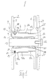
- FIG. 1 shows a longitudinal section through a fishing reel 1 according to the invention with a coil 2, which is me with their hollow spool core 3 mounted on an axle 4 peelable.
- the coil 2 is shown in the present drawing without fishing line.
- the fishing line is wound up on a spool core 3 in a ready-to-use spool.
- the coil 2 comprises an outer coil wall 5 and an inner coil wall 6.
- the coil core 3 has in its inner circumferential surface on a longitudinally extending U-groove 7, which is formed chamfered at its inner end 8.
- the coil core 3 has at one end 9 (opening 9) a larger inner diameter than at the opposite end 10.
- the inner circumference of the spool core 3 is formed in three stages, that is, that the inner circumference of the spool core is divided into three zones 11 a - 11 c, wherein the zone 11a has the largest inner diameter and the zone 11c has the smallest inner diameter.
- an annular groove 12 is introduced, which passes through the entire inner peripheral surface to the U-groove 7 annular.
- the axle 4 comprises the mechanism 13 of the roller, which is surrounded by a substantially cylindrical housing 14.
- the housing 14 of the axle 4 has at one end 15 a larger outer diameter than at the other end 16.
- the outer diameter of the housing 14 is divided into three stages 17a-17c with different outer diameters. Due to the different inner circumferences of the zones 11a - 11c of the spool core 3 and the different outer diameter of the housing 14 of the axle 4, the axle 4 can only be pushed from one end 16 into the end 9 of the spool core 3.
- the different inner diameters of the spool core 3 in the assembled state match with the different outer diameters of the housing 14, so that the axle 4 can be fitted in the spool core 3 in a form-fitting manner.
- a wedge-shaped element 18 is arranged, which projects beyond the outer circumference of the housing 14.
- the wedge-shaped element 18 engages when inserting the axis 4 in the spool core 3 in the groove 7 in the spool core 3, resulting in a positive connection of the bobbin 2 with the axis 4.
- the axis 4 is held in the bobbin 2 rotationally fixed.
- the axle 4 can only be inserted into the spool core 3 in such a way that the wedge-shaped element 18 engages in the groove 7.
- the housing 14 of the axle 4 also has an elastic locking element in the form of a ball 19, which is loaded in its guide 20 by a compression spring 21.
- the annular groove 12 in the spool core 3 serves as a locking receptacle for the pressure ball 19th
- the axis 4 is releasably connected by means of a screw 22 with a coil housing 23.
- the coil housing 23 is connected to a not shown here Rollenfuß for attachment to a fishing rod.
- a spacer ring 25 is arranged on the outside of the inner coil wall 6, .
- the spacer ring 25 is made of plastic.
- the spacer ring 25 of the bobbin 2 is limited at too high pressure in the axial direction to the rigid housing 23 out, so that the pressure balls 19 (a total of three pieces) bring the bobbin 2 again in the desired axial position.
- the play of the coil in the overall construction is severely limited, so that the pressure balls 19 remain in their rest position even at high pressure in the axial direction.
- a bearing 26 is arranged so that the coil 2 can rotate on the mechanism 13. Furthermore, sealing rings 27 are provided so that no water can escape into the bearing and no grease from the camp.
- the base housing may well be formed with a smaller outer diameter, with an approximately centrally disposed stabilizing ring is integrally formed on the housing, which has a larger outer diameter than one at the right end 16 of the axis 4 arranged end ring. It is also ensured by such an embodiment that the axle 4 can be inserted into the coil housing 2 only from one side.
Landscapes
- Life Sciences & Earth Sciences (AREA)
- Environmental Sciences (AREA)
- Animal Husbandry (AREA)
- Biodiversity & Conservation Biology (AREA)
Description
- Die vorliegende Erfindung betrifft eine Angelrolle, insbesondere für das Fliegenfischen, mit einer Spule, die mit ihrem ring- oder röhrenförmigen Nabenteil (Spulenkern) auf einer Achse abziehbar gelagert ist.
- Bei Angelrollen ist es oft gewünscht, dass die die Angelschnur aufnehmenden Spulen für verschiedene Einsatzzwecke ausgetauscht werden können. Bei bekannten Angelrollen, insbesondere Spezialrollen, die das Dual-Mode-System beinhalten, müssen entweder sehr kostenintensive Ersatzspulen eingesetzt werden oder Spulenkörper, die vom Innendurchmesser sehr groß ausgelegt sind (Großkernspulen), damit die Spule über die Mechanik geschoben werden kann. Die Ersatzspulen sind meist nur sehr aufwendig und/oder mit Spezialwerkzeug von der Mechanik zu trennen. Dokument
WO 03/061372 A2 - Der vorliegenden Erfindung liegt die Aufgabe zugrunde, eine Angelrolle zur Verfügung zu stellen, welche die Nachteile der Angelrollen aus dem Stand der Technik überwindet. Der vorliegenden Erfindung liegt insbesondere die Aufgabe zugrunde, eine Angelrolle zur Verfügung zu stellen, bei der neben der Reduzierung der Kosten von Ersatzspulen auch die Verwendung von kleinen Spulenkörpern möglich ist.
- Diese Aufgabe wird gelöst durch eine Angelrolle der eingangs genannten Art, die dadurch gekennzeichnet ist, dass die abziehbare Achse über mindestens eine lösbare Rastverbindung axial im Nabenteil fixiert ist und über mindestens eine formschlüssige Verbindung drehfest im Spulenkörper gehalten ist.
- Bei der erfindungsgemäßen Angelrolle kann die Spule auf einfache Art und Weise durch einfaches Abziehen von der sie tragenden Achse gelöst werden. Bei der erfindungsgemäßen Angelrolle weist die Achse mindestens ein elastisch vorgespanntes Rastelement auf, wobei in der inneren Umfangsfläche des Nabenteils des Spulenkörpers vorzugsweise mindestens eine Rastaufnahme zum Einrasten des Rastelementes vorgesehen ist.
- Erfindungsgemäß ist das mindestens eine Rastelement eine Kugel (Druckkugel), die in ihrer Führung von einer Druckfeder belastet ist. Durch derartige elastisch vorgespannte Rastelemente ist ein Wechseln der Spule besonders komfortabel möglich, indem der Kraftaufwand zum Abziehen der Spule von der Achse bzw. zum Aufschieben der Spule auf die Achse (bis zum Einrasten) niedrig ist.
- Mit Vorteil ist die mindestens eine Rastaufnahme eine Nut, vorzugsweise eine Ringnut. Eine derartige Nut ist einfach bei der Herstellung des Spulenkörpers in den Innenumfang des Spulenkerns einbringbar. Zum anderen weist eine derartige Nut den Vorteil auf, dass die Rastelemente, insbesondere Druckkugeln, an jeder beliebigen Stelle der Nut in diese einrastbar sind.
- Bei einer bevorzugten Ausführungsform der erfindungsgemäßen Angelrolle weist die Achse mindestens ein Mitnehmerelement, vorzugsweise einen Keil, Zapfen oder einen Stift auf, welches zur formschlüssigen Verbindung mit dem Spulenkörper in eine Vertiefung, vorzugsweise eine in Längsrichtung des Nabenteils verlaufende Nut, in der inneren Umfangsfläche des Nabenteils eingreift. Das Mitnehmerelement kann beispielsweise lösbar mit der Achse verbunden sein (z. B. verschraubt). Die mit dem Mitnehmerelement zusammenwirkende Vertiefung erstreckt sich vorzugsweise von einem äußeren Ende der inneren Umfangsfläche des Nabenteils bis ca. zur Mitte des Nabenteils. Die Breite der Vertiefung ist so bemessen, dass das Mitnehmerelement in der Vertiefung kaum bis überhaupt kein Spiel hat.
- Vorzugsweise weist das Nabenteil an einem Ende einen größeren Innendurchmesser auf als am anderen Ende, wobei der Innenumfang des Nabenteils vorzugsweise mehrstufig ausgebildet ist. In der Regel erhöht sich der Innendurchmesser des Nabenteils von einem Ende zum anderen Ende in mindestens einer, vorzugsweise drei Stufen. Auch kann sich der Innendurchmesser konisch verjüngen. Durch die Abnahme des Innendurchmessers von einem Ende zum anderen Ende wird u. a. erreicht, dass die Achse nur an einer Seite des Nabenteils in dieses eingeführt werden kann, da der Außendurchmesser der Achse an dessen breitester Stelle größer ist, als der Innendurchmesser des Nabenteils an einem der beiden Ende. Dadurch kann die Achse niemals "verkehrt" in den Spulenkörper eingeführt werden.
- Mit Vorteil umfasst die Achse ein Gehäuse, welches die Rollenmechanik aufnimmt und an welchem vorzugsweise die männlichen Verbindungsteile für die Rastverbindung bzw. die formschlüssige Verbindung mit dem Spulenkörper angeordnet sind. Die Achse bzw. das Gehäuse der Achse muss nicht geschlossen ausgebildet sein, d. h. die Achse bzw. das Gehäuse können Materialaussparungen aufweisen. Dies trägt zu einer Gewichtsreduzierung bei.
- Mit Vorteil weist die Achse mindestens einen Stabilisierungsring auf. Ein derartiger Stabilisierungsring kann beispielsweise im Wesentlichen mittig auf der Achse angeordnet sein. Ein solcher Ring ist in der Regel einstückig mit dem Achsenkörper bzw. dem Gehäuse der Achse verbunden. Derartige Stabilisierungsringe dienen als Auflage für den Spulenkörper und verhindern ein Durchbiegen desselben beispielsweise bei einem Aufrollen unter Last der Angelschnur auf die Spule (zum Beispiel beim Drillen eines Fisches).
- In der Regel ist an einem Ende der Achse eine Handkurbel zur Betätigung der Angelrolle angeordnet. Diese Handkurbel kann auswechselbar an der Achse angeordnet sein.
- In der Regel ist die Achse an einem Ende mit einem Spulengehäuse lösbar verbunden, vorzugsweise verschraubt. Das Spulengehäuse weist in der Regel einen Fuß auf, welcher die gesamte Angelrolle mit der Angelrute verbindet und über den beide Elemente miteinander verbunden sind. Durch die lösbare Verbindung der Achse mit dem Spulengehäuse ist ein äußerst einfaches Montieren bzw. Demontieren der Angelrolle möglich.
- Vorzugsweise weist die Spule an der Außenseite einer Spulenwand einen Distanzring auf. Dieser Distanzring ist insbesondere an derjenigen Außenseite der Spule angeordnet, an welcher die Achse mit dem Spulengehäuse verbunden ist. Durch den genannten Distanzring wird der Spulenkörper bei zu großem Druck in axialer Richtung zum starren Gehäuse hin begrenzt, damit die Rastelemente den Spulenkörper immer wieder in die gewünschte axiale Position bringen. Durch den Distanzring wird das Spiel der Spule in der Gesamtkonstruktion stark eingeschränkt, so dass die Rastelemente auch bei großem Druck in axialer Richtung in ihrer Rastposition verbleiben.
- Vorzugsweise weist die Achse in einem inneren Bereich einen größeren Durchmesser auf als im Bereich desjenigen Endes, welches mit dem Spulengehäuse lösbar verbunden ist. Dies ergibt - wie bereits oben angedeutet- den Vorteil, dass die Achse immer nur von einer Seite in das Spulengehäuse eingeschoben werden kann.
- Weitere Merkmale der Erfindung ergeben sich aus der nachfolgenden Beschreibung von bevorzugten Ausführungsformen der Erfindung in Verbindung mit der Zeichnung und den Unteransprüchen. Hierbei können die einzelnen Merkmale jeweils für sich allein oder in Kombination miteinander verwirklicht sein.
- In der Zeichnung zeigt:
- Figur 1:
- Einen Längsschnitt durch eine erfindungsgemäße Angelrolle.
-
Figur 1 zeigt einen Längsschnitt durch eine erfindungsgemäße Angelrolle 1 mit einer Spule 2, die mir ihrem hohlen Spulenkern 3 auf einer Achse 4 abziehbar gelagert ist. Die Spule 2 ist in der vorliegenden Zeichnung ohne Angelschnur dargestellt. Die Angelschnur ist bei einer einsatzfertigen Spule auf dem Spulenkern 3 aufgewickelt. Die Spule 2 umfasst eine äußere Spulenwand 5 und eine innere Spulenwand 6. Der Spulenkern 3 weist in seiner inneren Umfangsfläche eine in Längsrichtung verlaufende U-Nut 7 auf, welche an ihrem inneren Ende 8 abgeschrägt ausgebildet ist. Der Spulenkern 3 weist an einem Ende 9 (Öffnung 9) einen größeren Innendurchmesser auf als an dem gegenüberliegenden Ende 10. Der Innenumfang des Spulenkerns 3 ist dreistufig ausgebildet, das heißt, dass der Innenumfang des Spulenkerns in drei Zonen 11 a - 11c unterteilt ist, wobei die Zone 11a den größten Innendurchmesser und die Zone 11c den geringsten Innendurchmesser aufweist. In die Zone 11 a der inneren Umfangsfläche des Spulenkerns 3 ist eine Ringnut 12 eingebracht, welche die gesamte innere Umfangsfläche bis zur U-Nut 7 ringförmig durchzieht. - Die Achse 4 umfasst die Mechanik 13 der Rolle, die von einem im Wesentlichen walzenförmigen Gehäuse 14 umgeben ist. Das Gehäuse 14 der Achse 4 weist an einem Ende 15 einen größeren Außendurchmesser als am anderen Ende 16 auf. Der Außendurchmesser des Gehäuses 14 ist in drei Stufen 17a - 17c mit unterschiedlichen Außendurchmessern geteilt. Durch die unterschiedlichen Innenumfänge der Zonen 11a - 11c des Spulenkerns 3 und die unterschiedlichen Außendurchmesser des Gehäuses 14 der Achse 4 kann die Achse 4 nur von einem Ende 16 in das Ende 9 des Spulenkerns 3 geschoben werden. Die unterschiedlichen Innendurchmesser des Spulenkerns 3 passen im zusammengesetzten Zustand mit den unterschiedlichen Außendurchmessern des Gehäuses 14 zusammen, sodass die Achse 4 in den Spulenkern 3 formschlüssig eingepasst werden kann.
- Am Gehäuse 14 ist ein keilförmiges Element 18 angeordnet, welches über den Außenumfang des Gehäuses 14 hinausragt. Das keilförmige Element 18 greift beim Einschieben der Achse 4 in den Spulenkern 3 in die Nut 7 im Spulenkern 3 ein, was zu einer formschlüssigen Verbindung des Spulenkörpers 2 mit der Achse 4 führt. Durch diese Verbindung wird die Achse 4 drehfest im Spulenkörper 2 gehalten. Die Achse 4 kann nur so in den Spulenkern 3 eingeschoben werden, dass das keilförmige Element 18 in die Nut 7 eingreift. Ein Einschieben der Achse 4 an einer anderen Stelle ist nicht möglich, da das keilförmige Element über den Außenumfang des Gehäuses 14 der Achse 4 hinausragt und der Innendurchmesser des Spulenkerns 3 auch im Bereich der größeren Öffnung 9 des Spulenkerns 3 so bemessen ist, dass das keilförmige Element nicht an einer anderen Stelle in den Spulenkern 3 eingeschoben werden kann.
- Das Gehäuse 14 der Achse 4 weist ferner ein elastisches Rastelement in Form einer Kugel 19 auf, die in ihrer Führung 20 von einer Druckfeder 21 belastet ist. Die Ringnut 12 im Spulenkern 3 dient als Rastaufnahme für die Druckkugel 19.
- An einer Stirnfläche 24 ist die Achse 4 mittels einer Schraube 22 mit einem Spulengehäuse 23 lösbar verbunden. Das Spulengehäuse 23 ist mit einem hier nicht dargestellten Rollenfuß zur Befestigung an einer Angelrute verbunden.
- An der der genannten Stirnfläche 24 gegenüberliegenden Stirnfläche der Achse 4 ist eine hier nicht dargestellte Handkurbel angeordnet.
- An der Außenseite der inneren Spulenwand 6 ist ein Distanzring 25 angeordnet. Der Distanzring 25 ist aus Kunststoff gefertigt. Durch den Distanzring 25 wird der Spulenkörper 2 bei zu großem Druck in axialer Richtung zum starren Gehäuse 23 hin begrenzt, damit die Druckkugeln 19 (insgesamt drei Stück) den Spulenkörper 2 immer wieder in die gewünschte axiale Position bringen. Durch den Distanzring wird das Spiel der Spule in der Gesamtkonstruktion stark eingeschränkt, sodass die Druckkugeln 19 auch bei großem Druck in axialer Richtung in ihrer Rastposition verbleiben.
- Zwischen dem Gehäuse 14 und der Mechanik 13 ist ein Lager 26 angeordnet, damit sich die Spule 2 auf der Mechanik 13 drehen kann. Ferner sind Dichtringe 27 vorgesehen, damit kein Wasser in das Lager hinein und kein Schmierfett aus dem Lager entweichen kann.
- Zur Demontage der Angelrolle 1 beziehungsweise zum Auswechseln der Spule 2 muss lediglich die Schraube 22 gelöst werden, um die Angelrolle 1 vom Spulengehäuse 23 zu trennen. Anschließend muss nur vom rechten Ende 16 der Achse 4 auf die Stirnfläche 24 der Achse 4 gedrückt beziehungsweise von der gegenüberliegenden Seite der Achse 4 an dieser gezogen werden, um die Rastverbindung zwischen den Druckkugeln 19 und der Ringnut 12 zu lösen und die Achse 4 aus dem Spulengehäuse 2 zu entnehmen.
- Anstatt der gezeigten Ausbildung des Gehäuses 14 der Achse 4 mit dreifach abgestuftem Außendurchmesser kann das Grundgehäuse durchaus auch mit einem geringeren Außendurchmesser ausgebildet sein, wobei ein etwa mittig angeordneter Stabilisierungsring am Gehäuse angeformt ist, welcher einen größeren Außendurchmesser aufweist als ein am rechten Ende 16 der Achse 4 angeordneter Abschlussring. Auch durch eine solche Ausführungsform wird gewährleistet, dass die Achse 4 nur von einer Seite in das Spulengehäuse 2 eingeführt werden kann.
Claims (9)
- Angelrolle, insbesondere für das Fliegenfischen, mit einer Spule (2), die mit ihrem ring- oder röhrenförmigen Nabenteil (3) auf einer Achse (4) abziehbar gelagert ist, wobei die abziehbare Achse über mindestens eine lösbare Rastverbindung axial im Nabenteil fixiert ist und über mindestens eine formschlüssige Verbindung drehfest im Spulenkörper gehalten ist, dadurch gekennzeichnet, dass die Achse (4) mindestens ein elastisch vorgespanntes Rastelement (19) aufweist, wobei in der inneren Umfangsfläche des Nabenteils (3) des Spulenkörpers (2) mindestens eine Rastaufnahme (12) zum Einrasten des Rastelementes vorgesehen ist, wobei das mindestens eine Rastelement eine Kugel (19) ist, die in ihrer Führung (20) von einer Druckfeder (21) belastet ist.
- Angelrolle nach Anspruch 1, dadurch gekennzeichnet, dass die mindestens eine Rastaufnahme eine Nut, vorzugsweise eine Ringnut (12) ist.
- Angelrolle nach einem der vorhergehenden Ansprüche, dadurch gekennzeichnet, dass die Achse (4) mindestens ein Mitnehmerelement (18), vorzugsweise einen Keil, Zapfen oder einen Stift, aufweist, welches zur formschlüssigen Verbindung mit dem Spulenkörper (2) in eine Vertiefung, vorzugsweise eine in Längsrichtung des Nabenteils verlaufende Nut (7), in der inneren Umfangsfläche des Nabenteils (3) eingreift.
- Angelrolle nach einem der vorhergehenden Ansprüche, dadurch gekennzeichnet, dass das Nabenteil (3) an einem Ende (9) einen größeren Innendurchmesser aufweist als am anderen Ende (10), wobei der Innenumfang des Nabenteils vorzugsweise mehrstufig ausgebildet ist.
- Angelrolle nach einem der vorhergehenden Ansprüche, dadurch gekennzeichnet, dass die Achse (4) ein Gehäuse (14) umfasst, welches die Rollenmechanik (13) aufnimmt und an welchem vorzugsweise die männlichen Verbindungsteile (19,18) für die Rastverbindung bzw. die formschlüssige Verbindung mit dem Spulenkörper (2) angeordnet sind.
- Angelrolle nach einem der vorhergehenden Ansprüche, dadurch gekennzeichnet, dass die Achse (4) mindestens ein Stabilisierungselement, vorzugsweise einen Stabilisierungsring aufweist.
- Angelrolle nach einem der vorhergehenden Ansprüche, dadurch gekennzeichnet, dass an einem Ende (15) der Achse (4) eine Handkurbel angeordnet ist.
- Angelrolle nach einem der vorhergehenden Ansprüche, dadurch gekennzeichnet, dass die Achse (4) an einem Ende (16) mit einem Spulengehäuse (23) lösbar verbunden, vorzugsweise verschraubt ist.
- Angelrolle nach einem der vorhergehenden Ansprüche, dadurch gekennzeichnet, dass die Spule (2) an der Außenseite einer Spulenwand (6) einen Distanzring (25) aufweist.
Applications Claiming Priority (3)
| Application Number | Priority Date | Filing Date | Title |
|---|---|---|---|
| DE102009037509 | 2009-08-17 | ||
| DE102009056825A DE102009056825B4 (de) | 2009-08-17 | 2009-12-04 | Angelrolle, insbesondere für das Fliegenfischen |
| PCT/DE2010/000863 WO2011020453A1 (de) | 2009-08-17 | 2010-07-23 | Angelrolle, insbesondere für das fliegenfischen |
Publications (2)
| Publication Number | Publication Date |
|---|---|
| EP2467015A1 EP2467015A1 (de) | 2012-06-27 |
| EP2467015B1 true EP2467015B1 (de) | 2015-09-09 |
Family
ID=43037910
Family Applications (1)
| Application Number | Title | Priority Date | Filing Date |
|---|---|---|---|
| EP10747798.6A Active EP2467015B1 (de) | 2009-08-17 | 2010-07-23 | Angelrolle, insbesondere für das fliegenfischen |
Country Status (6)
| Country | Link |
|---|---|
| US (1) | US8662434B2 (de) |
| EP (1) | EP2467015B1 (de) |
| CA (1) | CA2770344C (de) |
| DE (1) | DE102009056825B4 (de) |
| DK (1) | DK2467015T3 (de) |
| WO (1) | WO2011020453A1 (de) |
Families Citing this family (3)
| Publication number | Priority date | Publication date | Assignee | Title |
|---|---|---|---|---|
| US9217234B2 (en) | 2013-03-13 | 2015-12-22 | Harnischfeger Technologies, Inc. | Reel with stepped configuration |
| US9185893B1 (en) | 2013-09-09 | 2015-11-17 | Danny A. Heaton | Fishing reel |
| US11058100B1 (en) * | 2018-06-01 | 2021-07-13 | Jeff Crawford, Jr. | Open face fishing reel with quick-release spool |
Citations (1)
| Publication number | Priority date | Publication date | Assignee | Title |
|---|---|---|---|---|
| US6467712B1 (en) * | 2001-05-24 | 2002-10-22 | Harry L. Cribb | Fishing reel |
Family Cites Families (13)
| Publication number | Priority date | Publication date | Assignee | Title |
|---|---|---|---|---|
| DE8025268U1 (de) * | 1980-09-20 | 1981-02-12 | K.K.P. Konstruktive Kunststoff-Produkte Handelsgesellschaft Mbh, 8744 Mellrichstadt | Angelrolle, insbesondere fuer das fliegenfischen |
| US4733830A (en) * | 1985-09-23 | 1988-03-29 | Hollander William J | Fishing reel |
| GB8529192D0 (en) * | 1985-11-27 | 1986-01-02 | British Fly Reels Ltd | Fishing reel |
| FR2643544B1 (fr) * | 1989-02-27 | 1991-05-10 | Mitchell Sports | Moulinet de peche a bobine demontable a reduction de jeu |
| US5120003A (en) * | 1990-08-02 | 1992-06-09 | Sacconi Roberto L | Changeable fishing reel cartridge with line |
| EP0472437A1 (de) * | 1990-08-24 | 1992-02-26 | David Lorne Stevenson | Eine Angelwinde |
| FR2709922B1 (fr) * | 1993-09-14 | 1995-10-27 | Mitchell Sports | Moulinet de pêche à bobine enveloppée et dispositif de retenue du fil. |
| NL1002263C2 (nl) | 1996-02-06 | 1997-08-07 | Enev B V | Draadwikkelmolen voor de vissport. |
| US5755391A (en) * | 1996-02-09 | 1998-05-26 | Sacconi; Roberto Luis | Fishing reel with a lockable, changeable cartridge spool |
| US6712300B2 (en) * | 2001-12-10 | 2004-03-30 | Better Fishtrap, Inc. | Methods and apparatus for a quick-change spool system |
| US7077350B2 (en) | 2002-01-24 | 2006-07-18 | W.C. Bradley/Zebco Holdings, Inc. | Modular fly fishing reel |
| JP4785448B2 (ja) | 2005-07-20 | 2011-10-05 | 株式会社シマノ | 釣り用リール部品 |
| GB0801393D0 (en) | 2008-01-25 | 2008-03-05 | Hardy & Greys Ltd | Fishing reel with changeable cartridge spool |
-
2009
- 2009-12-04 DE DE102009056825A patent/DE102009056825B4/de not_active Expired - Fee Related
-
2010
- 2010-07-23 CA CA2770344A patent/CA2770344C/en active Active
- 2010-07-23 EP EP10747798.6A patent/EP2467015B1/de active Active
- 2010-07-23 DK DK10747798.6T patent/DK2467015T3/en active
- 2010-07-23 WO PCT/DE2010/000863 patent/WO2011020453A1/de not_active Ceased
- 2010-07-23 US US13/390,634 patent/US8662434B2/en active Active
Patent Citations (1)
| Publication number | Priority date | Publication date | Assignee | Title |
|---|---|---|---|---|
| US6467712B1 (en) * | 2001-05-24 | 2002-10-22 | Harry L. Cribb | Fishing reel |
Also Published As
| Publication number | Publication date |
|---|---|
| DK2467015T3 (en) | 2015-12-14 |
| WO2011020453A1 (de) | 2011-02-24 |
| US8662434B2 (en) | 2014-03-04 |
| EP2467015A1 (de) | 2012-06-27 |
| CA2770344A1 (en) | 2011-02-24 |
| DE102009056825A1 (de) | 2011-05-05 |
| US20120181365A1 (en) | 2012-07-19 |
| CA2770344C (en) | 2014-04-22 |
| DE102009056825B4 (de) | 2013-05-16 |
Similar Documents
| Publication | Publication Date | Title |
|---|---|---|
| DE2625960C2 (de) | Kreuzzapfengelenk | |
| AT12118U1 (de) | Wälzkörper eines laufwagenkäfigs für schubladenführungen | |
| EP2327518A2 (de) | Vorsatz für eine Werkzeugmaschine | |
| EP2236248B1 (de) | Vorrichtung zur Demontage eines Radlagergehäuses | |
| DE102007035754B4 (de) | Zerlegbarer Stock | |
| EP2467015B1 (de) | Angelrolle, insbesondere für das fliegenfischen | |
| EP2559617A2 (de) | Rudervorrichtung für ein Wasserfahrzeug | |
| DE102013003560B4 (de) | Fahrradnabenachsenadapter | |
| DE102016000291A1 (de) | Verfahren zum Herstellen einer Flanschverbindung, Verwendung, Flanschverbindung und Windenergieanlage | |
| DE1919439C3 (de) | Schnellspannfutter für einen Schaft aufweisende Werkzeuge | |
| DE69908873T2 (de) | Rotorblatt, insbesondere für einen heckrotor eines hubschraubers | |
| DE102018216687A1 (de) | Angelrolle | |
| EP3849436B1 (de) | Chirurgisches werkzeug mit lagerung | |
| DE6941979U (de) | Rollenpolierwerkzeug. | |
| DE6922091U (de) | Antrieb fuer angelrolle. | |
| AT395291B (de) | Ballschlaeger, insbesondere tennisracket | |
| EP3572312A1 (de) | Steuereinrichtung, zentrierelement und montageschablone für ein fahrrad | |
| DE202016103032U1 (de) | Mit schnell abbaubaren Antriebsrädern versehener Elektrorollstuhl | |
| DE102005001272B4 (de) | Endoskop | |
| EP3515372B1 (de) | Prothesenkupplung für eine prothese sowie prothese mit der prothesenkupplung | |
| EP1714785B1 (de) | Trägerwelle für die Aufnahme der Wickelkernhülsen von Tuchrollen | |
| DE202012103864U1 (de) | Sattelstützensystem | |
| DE102005050335B4 (de) | Vorrichtung zur Halterung von Rollen eines bahnförmigen Materials | |
| DE102006033540B4 (de) | Demontagewerkzeug für einen Kolbenbolzen-Sicherungsring | |
| WO2019122019A1 (de) | Windkraftanlage, rotorsystem, verfahren zur verwendung einer windkraftanlage |
Legal Events
| Date | Code | Title | Description |
|---|---|---|---|
| PUAI | Public reference made under article 153(3) epc to a published international application that has entered the european phase |
Free format text: ORIGINAL CODE: 0009012 |
|
| 17P | Request for examination filed |
Effective date: 20120206 |
|
| AK | Designated contracting states |
Kind code of ref document: A1 Designated state(s): AL AT BE BG CH CY CZ DE DK EE ES FI FR GB GR HR HU IE IS IT LI LT LU LV MC MK MT NL NO PL PT RO SE SI SK SM TR |
|
| DAX | Request for extension of the european patent (deleted) | ||
| GRAP | Despatch of communication of intention to grant a patent |
Free format text: ORIGINAL CODE: EPIDOSNIGR1 |
|
| INTG | Intention to grant announced |
Effective date: 20150421 |
|
| GRAS | Grant fee paid |
Free format text: ORIGINAL CODE: EPIDOSNIGR3 |
|
| GRAA | (expected) grant |
Free format text: ORIGINAL CODE: 0009210 |
|
| AK | Designated contracting states |
Kind code of ref document: B1 Designated state(s): AL AT BE BG CH CY CZ DE DK EE ES FI FR GB GR HR HU IE IS IT LI LT LU LV MC MK MT NL NO PL PT RO SE SI SK SM TR |
|
| REG | Reference to a national code |
Ref country code: GB Ref legal event code: FG4D Free format text: NOT ENGLISH |
|
| REG | Reference to a national code |
Ref country code: AT Ref legal event code: REF Ref document number: 747325 Country of ref document: AT Kind code of ref document: T Effective date: 20150915 Ref country code: CH Ref legal event code: EP |
|
| REG | Reference to a national code |
Ref country code: IE Ref legal event code: FG4D Free format text: LANGUAGE OF EP DOCUMENT: GERMAN |
|
| REG | Reference to a national code |
Ref country code: DE Ref legal event code: R096 Ref document number: 502010010270 Country of ref document: DE |
|
| REG | Reference to a national code |
Ref country code: CH Ref legal event code: NV Representative=s name: FREI PATENTANWALTSBUERO AG, CH |
|
| REG | Reference to a national code |
Ref country code: DK Ref legal event code: T3 Effective date: 20151207 |
|
| REG | Reference to a national code |
Ref country code: SE Ref legal event code: TRGR |
|
| REG | Reference to a national code |
Ref country code: NL Ref legal event code: MP Effective date: 20150909 |
|
| PG25 | Lapsed in a contracting state [announced via postgrant information from national office to epo] |
Ref country code: LV Free format text: LAPSE BECAUSE OF FAILURE TO SUBMIT A TRANSLATION OF THE DESCRIPTION OR TO PAY THE FEE WITHIN THE PRESCRIBED TIME-LIMIT Effective date: 20150909 Ref country code: LT Free format text: LAPSE BECAUSE OF FAILURE TO SUBMIT A TRANSLATION OF THE DESCRIPTION OR TO PAY THE FEE WITHIN THE PRESCRIBED TIME-LIMIT Effective date: 20150909 Ref country code: GR Free format text: LAPSE BECAUSE OF FAILURE TO SUBMIT A TRANSLATION OF THE DESCRIPTION OR TO PAY THE FEE WITHIN THE PRESCRIBED TIME-LIMIT Effective date: 20151210 |
|
| REG | Reference to a national code |
Ref country code: NO Ref legal event code: T2 Effective date: 20150909 |
|
| REG | Reference to a national code |
Ref country code: LT Ref legal event code: MG4D |
|
| PG25 | Lapsed in a contracting state [announced via postgrant information from national office to epo] |
Ref country code: HR Free format text: LAPSE BECAUSE OF FAILURE TO SUBMIT A TRANSLATION OF THE DESCRIPTION OR TO PAY THE FEE WITHIN THE PRESCRIBED TIME-LIMIT Effective date: 20150909 Ref country code: ES Free format text: LAPSE BECAUSE OF FAILURE TO SUBMIT A TRANSLATION OF THE DESCRIPTION OR TO PAY THE FEE WITHIN THE PRESCRIBED TIME-LIMIT Effective date: 20150909 |
|
| PG25 | Lapsed in a contracting state [announced via postgrant information from national office to epo] |
Ref country code: NL Free format text: LAPSE BECAUSE OF FAILURE TO SUBMIT A TRANSLATION OF THE DESCRIPTION OR TO PAY THE FEE WITHIN THE PRESCRIBED TIME-LIMIT Effective date: 20150909 |
|
| PG25 | Lapsed in a contracting state [announced via postgrant information from national office to epo] |
Ref country code: CZ Free format text: LAPSE BECAUSE OF FAILURE TO SUBMIT A TRANSLATION OF THE DESCRIPTION OR TO PAY THE FEE WITHIN THE PRESCRIBED TIME-LIMIT Effective date: 20150909 Ref country code: EE Free format text: LAPSE BECAUSE OF FAILURE TO SUBMIT A TRANSLATION OF THE DESCRIPTION OR TO PAY THE FEE WITHIN THE PRESCRIBED TIME-LIMIT Effective date: 20150909 Ref country code: IT Free format text: LAPSE BECAUSE OF FAILURE TO SUBMIT A TRANSLATION OF THE DESCRIPTION OR TO PAY THE FEE WITHIN THE PRESCRIBED TIME-LIMIT Effective date: 20150909 Ref country code: SK Free format text: LAPSE BECAUSE OF FAILURE TO SUBMIT A TRANSLATION OF THE DESCRIPTION OR TO PAY THE FEE WITHIN THE PRESCRIBED TIME-LIMIT Effective date: 20150909 |
|
| PG25 | Lapsed in a contracting state [announced via postgrant information from national office to epo] |
Ref country code: PT Free format text: LAPSE BECAUSE OF FAILURE TO SUBMIT A TRANSLATION OF THE DESCRIPTION OR TO PAY THE FEE WITHIN THE PRESCRIBED TIME-LIMIT Effective date: 20160111 Ref country code: PL Free format text: LAPSE BECAUSE OF FAILURE TO SUBMIT A TRANSLATION OF THE DESCRIPTION OR TO PAY THE FEE WITHIN THE PRESCRIBED TIME-LIMIT Effective date: 20150909 Ref country code: RO Free format text: LAPSE BECAUSE OF FAILURE TO SUBMIT A TRANSLATION OF THE DESCRIPTION OR TO PAY THE FEE WITHIN THE PRESCRIBED TIME-LIMIT Effective date: 20150909 |
|
| REG | Reference to a national code |
Ref country code: DE Ref legal event code: R097 Ref document number: 502010010270 Country of ref document: DE |
|
| PLBE | No opposition filed within time limit |
Free format text: ORIGINAL CODE: 0009261 |
|
| STAA | Information on the status of an ep patent application or granted ep patent |
Free format text: STATUS: NO OPPOSITION FILED WITHIN TIME LIMIT |
|
| 26N | No opposition filed |
Effective date: 20160610 |
|
| PG25 | Lapsed in a contracting state [announced via postgrant information from national office to epo] |
Ref country code: SI Free format text: LAPSE BECAUSE OF FAILURE TO SUBMIT A TRANSLATION OF THE DESCRIPTION OR TO PAY THE FEE WITHIN THE PRESCRIBED TIME-LIMIT Effective date: 20150909 |
|
| PG25 | Lapsed in a contracting state [announced via postgrant information from national office to epo] |
Ref country code: BE Free format text: LAPSE BECAUSE OF NON-PAYMENT OF DUE FEES Effective date: 20160731 |
|
| PG25 | Lapsed in a contracting state [announced via postgrant information from national office to epo] |
Ref country code: MC Free format text: LAPSE BECAUSE OF FAILURE TO SUBMIT A TRANSLATION OF THE DESCRIPTION OR TO PAY THE FEE WITHIN THE PRESCRIBED TIME-LIMIT Effective date: 20150909 |
|
| PG25 | Lapsed in a contracting state [announced via postgrant information from national office to epo] |
Ref country code: FR Free format text: LAPSE BECAUSE OF NON-PAYMENT OF DUE FEES Effective date: 20160801 |
|
| REG | Reference to a national code |
Ref country code: FR Ref legal event code: ST Effective date: 20170331 |
|
| PG25 | Lapsed in a contracting state [announced via postgrant information from national office to epo] |
Ref country code: LU Free format text: LAPSE BECAUSE OF NON-PAYMENT OF DUE FEES Effective date: 20160723 |
|
| PG25 | Lapsed in a contracting state [announced via postgrant information from national office to epo] |
Ref country code: HU Free format text: LAPSE BECAUSE OF FAILURE TO SUBMIT A TRANSLATION OF THE DESCRIPTION OR TO PAY THE FEE WITHIN THE PRESCRIBED TIME-LIMIT; INVALID AB INITIO Effective date: 20100723 Ref country code: CY Free format text: LAPSE BECAUSE OF FAILURE TO SUBMIT A TRANSLATION OF THE DESCRIPTION OR TO PAY THE FEE WITHIN THE PRESCRIBED TIME-LIMIT Effective date: 20150909 Ref country code: SM Free format text: LAPSE BECAUSE OF FAILURE TO SUBMIT A TRANSLATION OF THE DESCRIPTION OR TO PAY THE FEE WITHIN THE PRESCRIBED TIME-LIMIT Effective date: 20150909 |
|
| PG25 | Lapsed in a contracting state [announced via postgrant information from national office to epo] |
Ref country code: TR Free format text: LAPSE BECAUSE OF FAILURE TO SUBMIT A TRANSLATION OF THE DESCRIPTION OR TO PAY THE FEE WITHIN THE PRESCRIBED TIME-LIMIT Effective date: 20150909 Ref country code: MK Free format text: LAPSE BECAUSE OF FAILURE TO SUBMIT A TRANSLATION OF THE DESCRIPTION OR TO PAY THE FEE WITHIN THE PRESCRIBED TIME-LIMIT Effective date: 20150909 Ref country code: MT Free format text: LAPSE BECAUSE OF FAILURE TO SUBMIT A TRANSLATION OF THE DESCRIPTION OR TO PAY THE FEE WITHIN THE PRESCRIBED TIME-LIMIT Effective date: 20150909 |
|
| PG25 | Lapsed in a contracting state [announced via postgrant information from national office to epo] |
Ref country code: BG Free format text: LAPSE BECAUSE OF FAILURE TO SUBMIT A TRANSLATION OF THE DESCRIPTION OR TO PAY THE FEE WITHIN THE PRESCRIBED TIME-LIMIT Effective date: 20150909 |
|
| PG25 | Lapsed in a contracting state [announced via postgrant information from national office to epo] |
Ref country code: AL Free format text: LAPSE BECAUSE OF FAILURE TO SUBMIT A TRANSLATION OF THE DESCRIPTION OR TO PAY THE FEE WITHIN THE PRESCRIBED TIME-LIMIT Effective date: 20150909 |
|
| REG | Reference to a national code |
Ref country code: CH Ref legal event code: PCAR Free format text: NEW ADDRESS: POSTFACH, 8032 ZUERICH (CH) |
|
| PGFP | Annual fee paid to national office [announced via postgrant information from national office to epo] |
Ref country code: NO Payment date: 20230720 Year of fee payment: 14 Ref country code: IE Payment date: 20230726 Year of fee payment: 14 Ref country code: GB Payment date: 20230724 Year of fee payment: 14 Ref country code: FI Payment date: 20230719 Year of fee payment: 14 Ref country code: CH Payment date: 20230801 Year of fee payment: 14 Ref country code: AT Payment date: 20230718 Year of fee payment: 14 |
|
| PGFP | Annual fee paid to national office [announced via postgrant information from national office to epo] |
Ref country code: SE Payment date: 20230724 Year of fee payment: 14 Ref country code: IS Payment date: 20230727 Year of fee payment: 14 Ref country code: DK Payment date: 20230724 Year of fee payment: 14 Ref country code: DE Payment date: 20230920 Year of fee payment: 14 |
|
| REG | Reference to a national code |
Ref country code: DE Ref legal event code: R119 Ref document number: 502010010270 Country of ref document: DE |
|
| REG | Reference to a national code |
Ref country code: DK Ref legal event code: EBP Effective date: 20240731 |
|
| REG | Reference to a national code |
Ref country code: CH Ref legal event code: PL |
|
| REG | Reference to a national code |
Ref country code: SE Ref legal event code: EUG |
|
| REG | Reference to a national code |
Ref country code: AT Ref legal event code: MM01 Ref document number: 747325 Country of ref document: AT Kind code of ref document: T Effective date: 20240723 |
|
| GBPC | Gb: european patent ceased through non-payment of renewal fee |
Effective date: 20240723 |
|
| PG25 | Lapsed in a contracting state [announced via postgrant information from national office to epo] |
Ref country code: DE Free format text: LAPSE BECAUSE OF NON-PAYMENT OF DUE FEES Effective date: 20250201 |
|
| PG25 | Lapsed in a contracting state [announced via postgrant information from national office to epo] |
Ref country code: FI Free format text: LAPSE BECAUSE OF NON-PAYMENT OF DUE FEES Effective date: 20240723 |
|
| PG25 | Lapsed in a contracting state [announced via postgrant information from national office to epo] |
Ref country code: NO Free format text: LAPSE BECAUSE OF NON-PAYMENT OF DUE FEES Effective date: 20240731 |
|
| PG25 | Lapsed in a contracting state [announced via postgrant information from national office to epo] |
Ref country code: CH Free format text: LAPSE BECAUSE OF NON-PAYMENT OF DUE FEES Effective date: 20240731 Ref country code: AT Free format text: LAPSE BECAUSE OF NON-PAYMENT OF DUE FEES Effective date: 20240723 |
|
| PG25 | Lapsed in a contracting state [announced via postgrant information from national office to epo] |
Ref country code: GB Free format text: LAPSE BECAUSE OF NON-PAYMENT OF DUE FEES Effective date: 20240723 |
|
| PG25 | Lapsed in a contracting state [announced via postgrant information from national office to epo] |
Ref country code: DK Free format text: LAPSE BECAUSE OF NON-PAYMENT OF DUE FEES Effective date: 20240731 |
|
| PG25 | Lapsed in a contracting state [announced via postgrant information from national office to epo] |
Ref country code: IE Free format text: LAPSE BECAUSE OF NON-PAYMENT OF DUE FEES Effective date: 20240723 |
|
| PG25 | Lapsed in a contracting state [announced via postgrant information from national office to epo] |
Ref country code: SE Free format text: LAPSE BECAUSE OF NON-PAYMENT OF DUE FEES Effective date: 20240724 |