EP2466211A1 - Appareil de cuisson et procédé de fonctionnement d'un appareil de cuisson - Google Patents
Appareil de cuisson et procédé de fonctionnement d'un appareil de cuisson Download PDFInfo
- Publication number
- EP2466211A1 EP2466211A1 EP11401647A EP11401647A EP2466211A1 EP 2466211 A1 EP2466211 A1 EP 2466211A1 EP 11401647 A EP11401647 A EP 11401647A EP 11401647 A EP11401647 A EP 11401647A EP 2466211 A1 EP2466211 A1 EP 2466211A1
- Authority
- EP
- European Patent Office
- Prior art keywords
- cooking chamber
- cooking
- door
- opening
- cooking appliance
- Prior art date
- Legal status (The legal status is an assumption and is not a legal conclusion. Google has not performed a legal analysis and makes no representation as to the accuracy of the status listed.)
- Granted
Links
- 238000010411 cooking Methods 0.000 title claims abstract description 210
- 238000000034 method Methods 0.000 title claims abstract description 35
- 238000001816 cooling Methods 0.000 claims description 36
- 238000010438 heat treatment Methods 0.000 claims description 6
- 235000013305 food Nutrition 0.000 description 16
- 238000000197 pyrolysis Methods 0.000 description 5
- 230000007246 mechanism Effects 0.000 description 3
- 230000015572 biosynthetic process Effects 0.000 description 2
- 238000004891 communication Methods 0.000 description 2
- 239000007788 liquid Substances 0.000 description 2
- 230000002238 attenuated effect Effects 0.000 description 1
- 238000004140 cleaning Methods 0.000 description 1
- 230000005494 condensation Effects 0.000 description 1
- 238000009833 condensation Methods 0.000 description 1
- 230000003247 decreasing effect Effects 0.000 description 1
- 238000007791 dehumidification Methods 0.000 description 1
- 238000001514 detection method Methods 0.000 description 1
- 230000006866 deterioration Effects 0.000 description 1
- 230000000694 effects Effects 0.000 description 1
- 238000002347 injection Methods 0.000 description 1
- 239000007924 injection Substances 0.000 description 1
- 238000009434 installation Methods 0.000 description 1
- 235000013372 meat Nutrition 0.000 description 1
- 230000003134 recirculating effect Effects 0.000 description 1
Images
Classifications
-
- F—MECHANICAL ENGINEERING; LIGHTING; HEATING; WEAPONS; BLASTING
- F24—HEATING; RANGES; VENTILATING
- F24C—DOMESTIC STOVES OR RANGES ; DETAILS OF DOMESTIC STOVES OR RANGES, OF GENERAL APPLICATION
- F24C15/00—Details
- F24C15/006—Arrangements for circulation of cooling air
-
- F—MECHANICAL ENGINEERING; LIGHTING; HEATING; WEAPONS; BLASTING
- F24—HEATING; RANGES; VENTILATING
- F24C—DOMESTIC STOVES OR RANGES ; DETAILS OF DOMESTIC STOVES OR RANGES, OF GENERAL APPLICATION
- F24C15/00—Details
- F24C15/02—Doors specially adapted for stoves or ranges
-
- F—MECHANICAL ENGINEERING; LIGHTING; HEATING; WEAPONS; BLASTING
- F24—HEATING; RANGES; VENTILATING
- F24C—DOMESTIC STOVES OR RANGES ; DETAILS OF DOMESTIC STOVES OR RANGES, OF GENERAL APPLICATION
- F24C15/00—Details
- F24C15/20—Removing cooking fumes
- F24C15/2007—Removing cooking fumes from oven cavities
-
- F—MECHANICAL ENGINEERING; LIGHTING; HEATING; WEAPONS; BLASTING
- F24—HEATING; RANGES; VENTILATING
- F24C—DOMESTIC STOVES OR RANGES ; DETAILS OF DOMESTIC STOVES OR RANGES, OF GENERAL APPLICATION
- F24C7/00—Stoves or ranges heated by electric energy
- F24C7/08—Arrangement or mounting of control or safety devices
Definitions
- the present invention relates to a cooking appliance with an opening device for the particular automatic opening of the cooking chamber and a method for operating such a cooking appliance.
- Cooking appliances are subject to a constant process of development in order to meet the ever-increasing requirements for energy efficiency.
- the cooking chamber of cooking appliances is getting better and better insulated. This has the consequence that the temperature in the cooking chamber sinks only very slowly, even if the radiators are completely switched off.
- an oven is used to roast a roast, it must first be run very hot in order to achieve a crust with a desired browning. Subsequently, however, the cooking space must be lowered quickly to a relatively low temperature in order to continue to cook the roast with a low temperature for several hours in the oven. Even in such a case, the user must actively intervene in the cooking process and, for example, open the door of the cooking chamber to cool the cooking chamber.
- Such intervention is annoying for a user.
- the intervention in the cooking process for example opening the door, can also be easily forgotten or in some situations not possible when the user is about to do other things. As a result, the cooking result can be greatly deteriorated.
- Another method for cooling the cooking chamber shows the DE 102008012681 A1 ,
- the hot air blower of the cooking chamber is used either for circulating the air in the oven or for the intake of fresh air. It should be generated in the same line an opposite flow of incoming fresh air and outflowing moist cooking chamber air.
- the disadvantage here is that the fresh air is sucked in from the negative pressure area behind the hot air blower. As a result, only a small air flow can be used for cooling, whereby long periods are required for cooling, in which the cooking process continues.
- the cooking appliance according to the invention comprises at least one cooking chamber which can be heated by means of at least one heating source. So that the heat is held in the cooking chamber, at least one door closing the cooking chamber is provided in order to close the cooking chamber. In order to enable a rapid cooling of the cooking chamber, at least one opening device is further provided which is suitable and designed to automatically open the cooking chamber door at least.
- Such ausgestaltetes cooking appliance offers many advantages.
- a significant advantage is that the opening of the cooking chamber door provides an effective way for rapid cooling of the oven.
- the automatic opening of the door is a significant advantage, since the opening of the door to cool the cooking chamber can not be forgotten. Even with long and / or complex cooking processes, which are controlled, for example, by automatic programs with highly fluctuating temperature profiles, the user no longer has to stay within reach of the cooking appliance for the entire time.
- a possibly provided manual opening of the door for rapid cooling of the cooking chamber can be done automatically by the cooking appliance according to the invention.
- the door of the opening device can be closed again. This makes it possible to briefly open the cooking chamber during a cooking process for cooling and then close it again. This is particularly useful when a cooking process is started with very high heat, then should be cooked at a low temperature.
- An automatic opening of the door is particularly useful at the end of a cooking process.
- a cooking process can be started and a user no longer has to remove the finished cooked food, for example a cake, directly from the oven at the end of the cooking process.
- the door is automatically opened at least a gap, allowing the cooking chamber to cool down.
- a control device is advantageously provided, which is in communication with the opening device.
- the function of the rapid cooling of the cooking chamber can also be easily integrated into existing operating profiles or linked to various functions.
- an actuating device is provided which is in communication with the opening device. It is also preferred that the actuating device is connected to the control device, and that the control device activates the opening device upon actuation of the actuating unit.
- the opening device can be realized by many functions. It is particularly preferred that the opening device is provided by motor, hydraulic, pneumatic and / or magnetic.
- the door can be opened, for example, via the method of a rack and closed again.
- the opening by means of a printing cylinder is useful.
- the door can, for example, by relieving the Pressure cylinder to be closed again. It may also be provided a spring, which pulls the door back to the closed position.
- other suitable mechanisms such as a motorized rotation axis on the door, can be provided for opening and closing the cooking chamber door.
- the opening device is arranged as inconspicuous as possible for design-technical reasons.
- opening devices such as toothed racks or pressure cylinders can be arranged in the bars of the cooking appliance housing. As a result, the opening devices would be housed substantially hidden.
- the opening device is suitable and adapted to set different opening widths.
- a rod or a slider which is provided for opening the door, be moved out to different heights to realize different gap widths between the door and the cooking chamber opening.
- the door does not have to be opened very far.
- a gap between 0.5 - 5 cm, preferably between 1 - 3 cm and particularly preferably a gap of 1.9 cm is sufficient in most cases to achieve an effective cooling of the cooking chamber.
- smaller gap widths, and larger gap widths to fully open the cooking chamber door are possible.
- the cooking chamber door is opened stepwise by the opening device.
- a stepwise opening can then be better avoided even a possible heating of the control panel and / or condensation on the control panel or other parts of the cooking appliance.
- a continuous opening of the door is possible.
- a fan may be provided that is suitable and designed to press the hot air from the cooking chamber.
- the support of such a fan may be advantageous.
- an existing recirculation fan could be used, which mixes hot and cold air in the oven, the air for cooling along the cooking chamber walls along and pushes hot air from the oven.
- At least one fan which may also be provided externally.
- a blower is preferred, which is arranged outside the cooking chamber and is connected to the cooking chamber either directly or via an intermediate piece.
- the blower can direct cold fresh air into the cooking chamber which pushes the hot air out of the cooking chamber through the door which is at least one gap wide open.
- a particularly effective cooling can be achieved.
- the blower (s) can also be connected to the control device.
- At least one sensor is associated with the opening device and / or the control device.
- the opening state of the door can be determined; on the other hand, the size of the gap can also be matched to the current situation. If the cooking space is particularly hot, for example, after a pyrolysis operation, it may be useful to gradually and slowly open the cooking chamber to avoid the jerky discharge of extremely hot air.
- the inventive method is suitable for operating a cooking appliance with at least one thermally heated cooking chamber.
- at least one door closes the cooking chamber is provided, which closes the at least one cooking chamber.
- At least one opening device is provided for the at least one cooking chamber door, by means of which the cooking chamber door can be automatically opened at least one gap in order to support a rapid cooling of the cooking chamber.
- Such a configured method is very advantageous.
- a considerable advantage is that the door of the cooking chamber can be opened automatically by means of the opening device at least one gap.
- the automatic opening of the cooking chamber a significant gain in convenience for a user is achieved, which does not have to remove a finished cooked food after launching a cooking process directly from the oven.
- Cooking appliances are now so well insulated that a food would continue to cook even with complete shutdown of the heating sources. This could make the food inedible at worst.
- automatic programs for cooking food in combination with the method according to the invention it may be possible, for example, to start a cooking process, such as baking a cake, without having to remain within reach of the cooking appliance to the cake after reaching the desired degree of browning from the oven or to open the door by hand.
- the cooking chamber door is opened automatically only after a predetermined time or from a predetermined temperature. As a result, it can be avoided that excessively hot and / or excessively moist air can escape from the cooking chamber in an abrupt manner. As a result, the heating of, for example, the control panel of the cooking appliance and also condensate formation can be better avoided. It is also conceivable that the cooking chamber door is initially only one step wide open and only after a predetermined time or from a predetermined cooking chamber temperature is opened to the provided for cooling gap width. Particularly advantageous, in addition to the opening of the cooking chamber door at the same time the hot air blower or the fan outside the cooking chamber blows the cold air from the outside into the oven, operated. Alternatively, in addition to the opening of the cooking chamber door simultaneously the external fan and the hot air blower can be operated.
- the automatic opening of the cooking chamber door is integrated into an operating profile.
- the opening of the door can represent the completion of a profile in order to avoid a Rothergaren a food.
- the food could be seared at very high temperatures directly in the oven until a crust with the desired browning is formed. Subsequently, the cooking chamber must be cooled as quickly as possible to a low temperature. This could be effectively achieved by automatically opening the door.
- the opening device is controlled manually in order to allow the cooking space to cool down as needed.
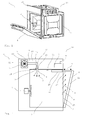
- FIG. 1 shows a cooking appliance 1 according to the invention that is designed here as oven 30 for installation in a furniture body.
- the oven 30 comprises a housing 24 in which a cooking chamber 2 which can be closed with a door 4 is arranged, in which food can be prepared using different operating profiles.
- a control panel 23 shown here only schematically.
- different heat sources 3 can be used to prepare the food.
- a recirculating air mode, top and bottom heat, and a grill function can be used.
- the temperature can also be adjusted.
- the control panel 23 may be designed as a touch panel or include controls not shown in detail.
- the cooking appliance 1 and in particular the cooking chamber 2 are very well insulated, whereby the heated cooking chamber 2 loses the introduced heat even after switching off the heat source 3 only very slowly. Although this is a great advantage for the energy balance of a cooking appliance 1, but also brings disadvantages in some situations.
- a user must immediately, or for example in automated programs with automatic detection of the finish time of the food, remove a food from the cooking chamber once it has finished cooking in order to prevent re-tanning or even burning of the food.
- the cooking chamber door must be opened by hand and, in particular, the food support accommodating the food item must additionally be pushed out at least as far as possible in order to release the hot air from the cooking space.
- the cooking chamber walls must be cooled. They store much more heat than the hot cooking air.
- the pyrolysis operation can cause loss of comfort for the user. If the device is finished with the pyrolysis operation, it may take a very long time until the cooking appliance is ready for use again. For safety reasons, the door can only be opened again after a certain temperature, which can take a long time to cool down up to 500 ° C.
- an opening device 10 is provided which is suitable and designed to open the cooking chamber door 4 at least one gap 7 far. An intervention of the user is then no longer necessary, since the opening device 10, the cooking chamber door 4 can open automatically.
- the opening device 10 can have a wide variety of configurations.
- the opening device 10 may be operated by a motor which, for example, displaces a rod and thus urges the door 4 a gap 7 far.
- a hydraulic, pneumatic and / or magnetic mechanism is advantageous for the formation of the opening device 10.
- opening devices 10 may be provided for opening and closing the cooking chamber door.
- the opening device is arranged as inconspicuous as possible for design-technical reasons.
- opening devices 10 such as toothed racks or pressure cylinders can be arranged in the bars of the cooking appliance housing 24. As a result, the opening devices 10 would be housed substantially hidden.
- the opening via a controllable pressure cylinder 26 which opens by means of a rod 27, the door 4 a bit wide.
- different opening widths 7 can be adjusted by the opening device 10.
- a particularly preferred opening width 7 is between 0.5 cm and 5 cm, wherein in FIG. 2 a gap 7 of 1.9 cm is set. Even larger and smaller opening widths 7 may be advantageous.
- the hot air 8 can escape quickly and effectively from the cooking chamber 2, as a result of which a cooling of the cooking chamber 2 takes place.
- the rod 27 can again move back into the cylinder 26, whereby the door 4 is closed again.
- the necessary force to close the door 4 can come either from the door 4 itself, but it is also conceivable that one here Not shown in detail pulling device, such as a spring is provided, which pulls the door 4 back to the cooking chamber 25.
- a control device 5 is provided in the exemplary embodiment shown here. This controls the automatic opening of the door 4 and can integrate the automatic opening of the door 4 in various operating profiles.
- the manual rapid cooling of the cooking chamber 2 is possible because an actuator 6 is provided which can trigger the opening device 10. This can be done either directly or via the control device 5.
- an opening 21 can escape via the hot air 8 from the cooking chamber 2.
- Such an opening 21 is then provided with a closure device 22, by means of which an automatic opening and closing of the opening 21 can be achieved.
- An advantageous arrangement of an additional opening 21 would be, for example, the lateral and / or rear region of the cooking chamber 2.
- the control device 5 can also suppress, for example, the opening of the door 4 or else it can be carried out stepwise if, for example, the temperature in the cooking chamber 2 is above a critical value. Then the door 4 would first open a small gap 7, so that the jerky escape of too hot vapor is avoided. After a first cooling, the door 4 can then be opened either directly to the desired opening width 7 or even gradually to cool the cooking chamber 2 as quickly as possible.
- the hot air blower 31 or another fan of the cooking appliance 1 can support the cooling.
- the cooking chamber 2 can be cooled when outside the cooking chamber 2, a fan 20 is arranged, which is suitable and oriented to direct cold fresh air 9 into the cooking chamber 20.
- the cold air 9 cools the cooking chamber 2 on the one hand effectively, on the other hand, the incoming air 9 presses the hot air 8 from the cooking chamber, whereby the cooling of the cooking chamber 2 can be done quickly.
- the blower 20 is designed as a radial fan 12, whereby a very effective air delivery is ensured.
- air volumes are greater than 800 l / min.
- the blower shown here can deliver about 1000 l / min. Even larger or smaller amounts of air can be advantageous depending on the application.
- the fan 20 is further designed as a DC fan 14, whereby a stepless control is possible.
- the control device 5 can also control the fan 20, wherein the sensor 11 in the example shown here can also determine the state of the blower 20.
- the blower 20 is arranged here in a housing 13 and blows the cold fresh air 9 via a connecting channel 19 in the cooking chamber. So that the air flow 17 is not attenuated too much, preferably at most one arc 28 is provided in the connection channel 19. Of course, several bends may be provided, which, however, a stronger fan 20 may be necessary. It should also be ensured that the connecting channel 19 is not laid out too long. In order not to impair the performance of the blower 20, a length of less than 30 cm is preferred. Also shorter or longer connecting channels 19 are conceivable, but possibly the fan 20 would have to be tuned to ensure adequate cooling.
- the connecting channel points in the in FIG. 2 embodiment shown, a seal 15 between the blower 20 and the cooking chamber 2.
- a flap device 16 is provided which closes the access 29 to the cooking chamber 2.
- the flapper device 16 is designed to be held in a closed position by, for example, a spring when the fan 20 is not turned on. The air flow 17 of the blower 20 can then press the flap device 16 and thus release the access 29 to the cooking chamber.
- Such a flap device 16 prevents hot air 8 from escaping from the cooking chamber 2 into the region between cooking chamber 2 and housing 24.
- the fan 20 may also be optionally, e.g. be used by the flap device 16 for cooling electrical and electronic components or for air injection into the cooking chamber, for the rapid cooling, or both at the same time.
- the cooking appliance 1 can also have the external fan 20 for rapid cooling in addition to the usual and required component cooling fans and Wrasenabsauggebläsen the cooking appliance 1 not shown here.
- an electronically controlled flap device may be provided. This could for example be related to the controller and be opened and closed as needed. Other seals 15 acting essentially as a valve are also conceivable.
- some cooking appliances for example, in the upper part of the Garraummuffel an opening through which the dehumidification of the cooking chamber takes place during a cooking process.
- This opening can be designed as a hole pattern.
- the fan 20 can replace the function of Garraumentfeuchtung, it is also possible in particular to use the space provided for Garraumentfeuchtung hole pattern as access 29 for the air flow 17.
- the hole pattern must be adjusted in size so that a sufficient amount of cold fresh air 9 can be pressed into the cooking chamber 2.
- an access of about 11 cm 2 is provided, which corresponds here to a hole pattern of 5.2 cm diameter with about 28 holes. It is thereby also possible to retrofit cooking appliances with a fan 20 for cooling the cooking chamber 2.
Landscapes
- Engineering & Computer Science (AREA)
- Chemical & Material Sciences (AREA)
- Combustion & Propulsion (AREA)
- Mechanical Engineering (AREA)
- General Engineering & Computer Science (AREA)
- Electric Stoves And Ranges (AREA)
- Electric Ovens (AREA)
Applications Claiming Priority (1)
| Application Number | Priority Date | Filing Date | Title |
|---|---|---|---|
| DE102010061339A DE102010061339A1 (de) | 2010-12-20 | 2010-12-20 | Gargerät und Verfahren zum Betreiben eines Gargerätes |
Publications (2)
| Publication Number | Publication Date |
|---|---|
| EP2466211A1 true EP2466211A1 (fr) | 2012-06-20 |
| EP2466211B1 EP2466211B1 (fr) | 2017-05-10 |
Family
ID=45319040
Family Applications (1)
| Application Number | Title | Priority Date | Filing Date |
|---|---|---|---|
| EP11401647.0A Active EP2466211B1 (fr) | 2010-12-20 | 2011-12-01 | Procédé de fonctionnement d'un appareil de cuisson |
Country Status (5)
| Country | Link |
|---|---|
| US (1) | US20120152223A1 (fr) |
| EP (1) | EP2466211B1 (fr) |
| DE (1) | DE102010061339A1 (fr) |
| ES (1) | ES2629879T3 (fr) |
| PL (1) | PL2466211T3 (fr) |
Cited By (6)
| Publication number | Priority date | Publication date | Assignee | Title |
|---|---|---|---|---|
| DE102012105340A1 (de) * | 2012-06-20 | 2013-12-24 | Miele & Cie. Kg | Verfahren zum Betreiben eines Hausgeräts und Hausgerät |
| WO2015002678A1 (fr) * | 2013-06-27 | 2015-01-08 | Middleby Marshall Holdings Llc D/B/A | Évacuation d'humidité forcée pour cuisson rapide |
| WO2017102494A1 (fr) * | 2015-12-17 | 2017-06-22 | Convotherm-Elektrogeräte Gmbh | Procédé permettant de faire fonctionner un appareil de cuisson industriel et appareil de cuisson |
| EP3647664A1 (fr) * | 2018-10-31 | 2020-05-06 | Miele & Cie. KG | Procédé de fonctionnement automatique d'un appareil de cuisson à la vapeur et appareil de cuisson à la vapeur correspondant |
| US10694753B2 (en) | 2013-05-23 | 2020-06-30 | Duke Manufacturing Co. | Food preparation apparatus and methods |
| US10918112B2 (en) | 2013-05-23 | 2021-02-16 | Duke Manufacturing Co. | Dough preparation apparatus and methods |
Families Citing this family (6)
| Publication number | Priority date | Publication date | Assignee | Title |
|---|---|---|---|---|
| US9341381B2 (en) * | 2012-12-12 | 2016-05-17 | Bsh Home Appliances Corporation | Home appliance with supplemental primary air supply |
| DE102014105117A1 (de) * | 2014-04-10 | 2015-10-15 | Miele & Cie. Kg | Gargerät und Verfahren zum Durchführen eines Pyrolyse-Reinigungsvorgangs |
| US10132515B2 (en) * | 2015-11-24 | 2018-11-20 | Electrolux Home Products, Inc. | Air curtain arrangement for an appliance, and associated apparatus and method |
| DE102019220294A1 (de) * | 2019-12-19 | 2021-06-24 | BSH Hausgeräte GmbH | Verfahren zum Betreiben eines Gargeräts mit automatischer Türöffnung, sowie Gargerät |
| BE1029396B1 (de) | 2021-05-11 | 2022-12-12 | Miele & Cie | Verfahren zum Kühlen des austretenden Wrasens oder Dampfs aus dem Garraum eines Gargeräts und Gargerät |
| DE102022126136A1 (de) | 2022-10-10 | 2024-04-11 | Rational Aktiengesellschaft | Verfahren zum Verhindern von Kondensation innerhalb eines Gargeräts |
Citations (4)
| Publication number | Priority date | Publication date | Assignee | Title |
|---|---|---|---|---|
| WO2000052392A1 (fr) * | 1999-03-04 | 2000-09-08 | Aktiebolaget Electrolux | Dispositif permettant de signaler la fin de la cuisson au four et d'indiquer l'etat dudit four |
| DE10327420A1 (de) | 2003-06-18 | 2005-01-13 | Rational Ag | Beschwadungsvorrichtung für ein Gargerät und Gargerät mit solch einer Beschwadungsvorrichtung |
| WO2005078352A1 (fr) * | 2004-02-12 | 2005-08-25 | Miele & Cie. Kg | Procede pour actionner un systeme d'affinage et dispositif de mise en oeuvre dudit procede |
| DE102008012681A1 (de) | 2008-03-05 | 2009-09-17 | Rational Ag | Be- und/oder Entlüftungsventil für ein Gargerät |
Family Cites Families (12)
| Publication number | Priority date | Publication date | Assignee | Title |
|---|---|---|---|---|
| US2907859A (en) * | 1958-02-19 | 1959-10-06 | Gen Electric | Domestic appliance |
| US3201565A (en) | 1962-01-03 | 1965-08-17 | King Seeleyt Thermos Co | Oven heating system |
| DE2739198C2 (de) | 1977-08-31 | 1985-06-27 | Küppersbusch AG, 4650 Gelsenkirchen | Gerät zum Garen von Eßwaren mittels Heißluft |
| US4420679A (en) | 1982-02-26 | 1983-12-13 | Delta Associates, Inc. | Gas chromatographic oven using symmetrical flow of preheated - premixed ambient air |
| FR2580059B1 (fr) | 1985-04-05 | 1989-12-15 | Moulinex Sa | |
| DE4019411A1 (de) * | 1990-06-18 | 1991-12-19 | Wss Waermetechnische Geraete S | Geraet zur waermebehandlung von lebensmitteln und dergleichen (mit automatischer tueroeffnung) |
| ATE193085T1 (de) * | 1995-01-05 | 2000-06-15 | Werner Lautenschlaeger | Vorrichtung zur wärmebehandlung von materialien in einer heizkammer |
| DE10027774C2 (de) * | 2000-04-20 | 2003-08-21 | Miwe Michael Wenz Gmbh | Vorrichtung zum Schließen der Tür eines Ofens und Ofen |
| US6809301B1 (en) * | 2000-06-30 | 2004-10-26 | General Electric Company | Oven control method and apparatus |
| DE10351476B4 (de) * | 2003-11-04 | 2008-09-25 | Rational Ag | Gargerät zur verbesserten Frischluftzufuhr |
| DE102007029194A1 (de) | 2007-06-25 | 2009-01-08 | BSH Bosch und Siemens Hausgeräte GmbH | Hocheinbau-Gargerät |
| GB2455783B (en) | 2007-12-21 | 2012-07-18 | Panasonic Mfg Uk Ltd | Controlled door opening in domestic appliances |
-
2010
- 2010-12-20 DE DE102010061339A patent/DE102010061339A1/de not_active Withdrawn
-
2011
- 2011-12-01 EP EP11401647.0A patent/EP2466211B1/fr active Active
- 2011-12-01 PL PL11401647T patent/PL2466211T3/pl unknown
- 2011-12-01 ES ES11401647.0T patent/ES2629879T3/es active Active
- 2011-12-19 US US13/329,522 patent/US20120152223A1/en not_active Abandoned
Patent Citations (4)
| Publication number | Priority date | Publication date | Assignee | Title |
|---|---|---|---|---|
| WO2000052392A1 (fr) * | 1999-03-04 | 2000-09-08 | Aktiebolaget Electrolux | Dispositif permettant de signaler la fin de la cuisson au four et d'indiquer l'etat dudit four |
| DE10327420A1 (de) | 2003-06-18 | 2005-01-13 | Rational Ag | Beschwadungsvorrichtung für ein Gargerät und Gargerät mit solch einer Beschwadungsvorrichtung |
| WO2005078352A1 (fr) * | 2004-02-12 | 2005-08-25 | Miele & Cie. Kg | Procede pour actionner un systeme d'affinage et dispositif de mise en oeuvre dudit procede |
| DE102008012681A1 (de) | 2008-03-05 | 2009-09-17 | Rational Ag | Be- und/oder Entlüftungsventil für ein Gargerät |
Cited By (11)
| Publication number | Priority date | Publication date | Assignee | Title |
|---|---|---|---|---|
| DE102012105340A1 (de) * | 2012-06-20 | 2013-12-24 | Miele & Cie. Kg | Verfahren zum Betreiben eines Hausgeräts und Hausgerät |
| US10694753B2 (en) | 2013-05-23 | 2020-06-30 | Duke Manufacturing Co. | Food preparation apparatus and methods |
| US10918112B2 (en) | 2013-05-23 | 2021-02-16 | Duke Manufacturing Co. | Dough preparation apparatus and methods |
| US11602149B2 (en) | 2013-05-23 | 2023-03-14 | Duke Manufacturing Co. | Food preparation apparatus and methods |
| US11779023B2 (en) | 2013-05-23 | 2023-10-10 | Duke Manufacturing Co. | Dough preparation apparatus and methods |
| WO2015002678A1 (fr) * | 2013-06-27 | 2015-01-08 | Middleby Marshall Holdings Llc D/B/A | Évacuation d'humidité forcée pour cuisson rapide |
| US9357787B2 (en) | 2013-06-27 | 2016-06-07 | Middleby Marshall Holdings Llc | Forced moisture evacuation for rapid baking |
| US9936706B2 (en) | 2013-06-27 | 2018-04-10 | Middleby Marshall Holding Llc | Forced moisture evacuation for rapid baking |
| WO2017102494A1 (fr) * | 2015-12-17 | 2017-06-22 | Convotherm-Elektrogeräte Gmbh | Procédé permettant de faire fonctionner un appareil de cuisson industriel et appareil de cuisson |
| US11690145B2 (en) | 2015-12-17 | 2023-06-27 | Convotherm-Elektrogerate Gmbh | Method for operating a commercial cooking device and such a cooking device |
| EP3647664A1 (fr) * | 2018-10-31 | 2020-05-06 | Miele & Cie. KG | Procédé de fonctionnement automatique d'un appareil de cuisson à la vapeur et appareil de cuisson à la vapeur correspondant |
Also Published As
| Publication number | Publication date |
|---|---|
| EP2466211B1 (fr) | 2017-05-10 |
| ES2629879T3 (es) | 2017-08-16 |
| US20120152223A1 (en) | 2012-06-21 |
| PL2466211T3 (pl) | 2017-09-29 |
| DE102010061339A1 (de) | 2012-06-21 |
Similar Documents
| Publication | Publication Date | Title |
|---|---|---|
| EP2466211B1 (fr) | Procédé de fonctionnement d'un appareil de cuisson | |
| EP3470739A1 (fr) | Appareil de cuisson et procédé de mise en uvre d'un procédé de traitement | |
| EP0926449B1 (fr) | Procédé pour déshumidifier un espace à cuire d'un dispositif pour cuire à la vapeur et dispositif approprié | |
| EP3500800B1 (fr) | Appareil de cuisson domestique | |
| DE102019205337A1 (de) | Vorrichtung zum Erhitzen von Gargut | |
| EP2775215B1 (fr) | Four de cuisson comprenant une limitation de température dépendant de l'atmosphère dans le four | |
| EP1619443B1 (fr) | Appareil de cuisson avec ventilation réglable | |
| EP2848868A1 (fr) | Four de cuisson doté de capteur d'humidité et de système de gestion de l'air | |
| EP3026167B1 (fr) | Appareil de séchage du linge et procédé de fonctionnement d'un appareil de séchage du linge | |
| EP1436550B1 (fr) | Appareil de cuisson comprenant un ventilateur a vapeurs | |
| DE19509569A1 (de) | Ofen zur Wärmebehandlung von Lebensmitteln und Verfahren zum Backen | |
| EP1855058A1 (fr) | Procédé et appareil de cuisson de plats à la vapeur | |
| DE102014107544A1 (de) | Backofen | |
| EP3176511B1 (fr) | Appareil de cuisson et procédé de réalisation d'un programme de cuisson | |
| EP2472187A1 (fr) | Appareil de cuisson et procédé de fonctionnement d'un appareil de cuisson | |
| EP3399245A2 (fr) | Appareil de cuisson | |
| EP1470369B1 (fr) | Four de cuisson | |
| EP3437478A1 (fr) | Appareil de cuisson et procédé | |
| EP1639299A1 (fr) | Four de cuisson | |
| EP2741013B1 (fr) | Appareil de cuisson avec un ventilateur et un dispositif de réglage | |
| DE202011110072U1 (de) | Gargerät zum Garen von Speisen, insbesondere für eine mobile Feldküche | |
| EP2860457A1 (fr) | Procédé de fonctionnement d'un appareil de cuisson et appareil de cuisson destiné à la réalisation du procédé | |
| EP2608635A1 (fr) | Appareil de cuisson et procédé de fonctionnement d'un appareil de cuisson | |
| DE102017103392A1 (de) | Gargerät | |
| DE102016121834A1 (de) | Gargerät |
Legal Events
| Date | Code | Title | Description |
|---|---|---|---|
| PUAI | Public reference made under article 153(3) epc to a published international application that has entered the european phase |
Free format text: ORIGINAL CODE: 0009012 |
|
| AK | Designated contracting states |
Kind code of ref document: A1 Designated state(s): AL AT BE BG CH CY CZ DE DK EE ES FI FR GB GR HR HU IE IS IT LI LT LU LV MC MK MT NL NO PL PT RO RS SE SI SK SM TR |
|
| AX | Request for extension of the european patent |
Extension state: BA ME |
|
| 17P | Request for examination filed |
Effective date: 20121220 |
|
| 17Q | First examination report despatched |
Effective date: 20160722 |
|
| STAA | Information on the status of an ep patent application or granted ep patent |
Free format text: STATUS: EXAMINATION IS IN PROGRESS |
|
| GRAP | Despatch of communication of intention to grant a patent |
Free format text: ORIGINAL CODE: EPIDOSNIGR1 |
|
| STAA | Information on the status of an ep patent application or granted ep patent |
Free format text: STATUS: GRANT OF PATENT IS INTENDED |
|
| INTG | Intention to grant announced |
Effective date: 20170116 |
|
| GRAS | Grant fee paid |
Free format text: ORIGINAL CODE: EPIDOSNIGR3 |
|
| GRAA | (expected) grant |
Free format text: ORIGINAL CODE: 0009210 |
|
| STAA | Information on the status of an ep patent application or granted ep patent |
Free format text: STATUS: THE PATENT HAS BEEN GRANTED |
|
| AK | Designated contracting states |
Kind code of ref document: B1 Designated state(s): AL AT BE BG CH CY CZ DE DK EE ES FI FR GB GR HR HU IE IS IT LI LT LU LV MC MK MT NL NO PL PT RO RS SE SI SK SM TR |
|
| REG | Reference to a national code |
Ref country code: GB Ref legal event code: FG4D Free format text: NOT ENGLISH |
|
| REG | Reference to a national code |
Ref country code: AT Ref legal event code: REF Ref document number: 892765 Country of ref document: AT Kind code of ref document: T Effective date: 20170515 Ref country code: CH Ref legal event code: EP |
|
| REG | Reference to a national code |
Ref country code: IE Ref legal event code: FG4D Free format text: LANGUAGE OF EP DOCUMENT: GERMAN |
|
| REG | Reference to a national code |
Ref country code: DE Ref legal event code: R096 Ref document number: 502011012196 Country of ref document: DE |
|
| REG | Reference to a national code |
Ref country code: ES Ref legal event code: FG2A Ref document number: 2629879 Country of ref document: ES Kind code of ref document: T3 Effective date: 20170816 |
|
| REG | Reference to a national code |
Ref country code: NL Ref legal event code: MP Effective date: 20170510 |
|
| REG | Reference to a national code |
Ref country code: LT Ref legal event code: MG4D |
|
| PG25 | Lapsed in a contracting state [announced via postgrant information from national office to epo] |
Ref country code: GR Free format text: LAPSE BECAUSE OF FAILURE TO SUBMIT A TRANSLATION OF THE DESCRIPTION OR TO PAY THE FEE WITHIN THE PRESCRIBED TIME-LIMIT Effective date: 20170811 Ref country code: HR Free format text: LAPSE BECAUSE OF FAILURE TO SUBMIT A TRANSLATION OF THE DESCRIPTION OR TO PAY THE FEE WITHIN THE PRESCRIBED TIME-LIMIT Effective date: 20170510 Ref country code: FI Free format text: LAPSE BECAUSE OF FAILURE TO SUBMIT A TRANSLATION OF THE DESCRIPTION OR TO PAY THE FEE WITHIN THE PRESCRIBED TIME-LIMIT Effective date: 20170510 Ref country code: NO Free format text: LAPSE BECAUSE OF FAILURE TO SUBMIT A TRANSLATION OF THE DESCRIPTION OR TO PAY THE FEE WITHIN THE PRESCRIBED TIME-LIMIT Effective date: 20170810 Ref country code: LT Free format text: LAPSE BECAUSE OF FAILURE TO SUBMIT A TRANSLATION OF THE DESCRIPTION OR TO PAY THE FEE WITHIN THE PRESCRIBED TIME-LIMIT Effective date: 20170510 |
|
| PG25 | Lapsed in a contracting state [announced via postgrant information from national office to epo] |
Ref country code: LV Free format text: LAPSE BECAUSE OF FAILURE TO SUBMIT A TRANSLATION OF THE DESCRIPTION OR TO PAY THE FEE WITHIN THE PRESCRIBED TIME-LIMIT Effective date: 20170510 Ref country code: RS Free format text: LAPSE BECAUSE OF FAILURE TO SUBMIT A TRANSLATION OF THE DESCRIPTION OR TO PAY THE FEE WITHIN THE PRESCRIBED TIME-LIMIT Effective date: 20170510 Ref country code: NL Free format text: LAPSE BECAUSE OF FAILURE TO SUBMIT A TRANSLATION OF THE DESCRIPTION OR TO PAY THE FEE WITHIN THE PRESCRIBED TIME-LIMIT Effective date: 20170510 Ref country code: IS Free format text: LAPSE BECAUSE OF FAILURE TO SUBMIT A TRANSLATION OF THE DESCRIPTION OR TO PAY THE FEE WITHIN THE PRESCRIBED TIME-LIMIT Effective date: 20170910 Ref country code: BG Free format text: LAPSE BECAUSE OF FAILURE TO SUBMIT A TRANSLATION OF THE DESCRIPTION OR TO PAY THE FEE WITHIN THE PRESCRIBED TIME-LIMIT Effective date: 20170810 Ref country code: SE Free format text: LAPSE BECAUSE OF FAILURE TO SUBMIT A TRANSLATION OF THE DESCRIPTION OR TO PAY THE FEE WITHIN THE PRESCRIBED TIME-LIMIT Effective date: 20170510 |
|
| REG | Reference to a national code |
Ref country code: FR Ref legal event code: PLFP Year of fee payment: 7 |
|
| PG25 | Lapsed in a contracting state [announced via postgrant information from national office to epo] |
Ref country code: DK Free format text: LAPSE BECAUSE OF FAILURE TO SUBMIT A TRANSLATION OF THE DESCRIPTION OR TO PAY THE FEE WITHIN THE PRESCRIBED TIME-LIMIT Effective date: 20170510 Ref country code: SK Free format text: LAPSE BECAUSE OF FAILURE TO SUBMIT A TRANSLATION OF THE DESCRIPTION OR TO PAY THE FEE WITHIN THE PRESCRIBED TIME-LIMIT Effective date: 20170510 Ref country code: EE Free format text: LAPSE BECAUSE OF FAILURE TO SUBMIT A TRANSLATION OF THE DESCRIPTION OR TO PAY THE FEE WITHIN THE PRESCRIBED TIME-LIMIT Effective date: 20170510 Ref country code: CZ Free format text: LAPSE BECAUSE OF FAILURE TO SUBMIT A TRANSLATION OF THE DESCRIPTION OR TO PAY THE FEE WITHIN THE PRESCRIBED TIME-LIMIT Effective date: 20170510 Ref country code: RO Free format text: LAPSE BECAUSE OF FAILURE TO SUBMIT A TRANSLATION OF THE DESCRIPTION OR TO PAY THE FEE WITHIN THE PRESCRIBED TIME-LIMIT Effective date: 20170510 |
|
| REG | Reference to a national code |
Ref country code: DE Ref legal event code: R026 Ref document number: 502011012196 Country of ref document: DE |
|
| PLBI | Opposition filed |
Free format text: ORIGINAL CODE: 0009260 |
|
| PLAX | Notice of opposition and request to file observation + time limit sent |
Free format text: ORIGINAL CODE: EPIDOSNOBS2 |
|
| PG25 | Lapsed in a contracting state [announced via postgrant information from national office to epo] |
Ref country code: SM Free format text: LAPSE BECAUSE OF FAILURE TO SUBMIT A TRANSLATION OF THE DESCRIPTION OR TO PAY THE FEE WITHIN THE PRESCRIBED TIME-LIMIT Effective date: 20170510 |
|
| 26 | Opposition filed |
Opponent name: BSH HAUSGERAETE GMBH Effective date: 20180206 |
|
| PG25 | Lapsed in a contracting state [announced via postgrant information from national office to epo] |
Ref country code: SI Free format text: LAPSE BECAUSE OF FAILURE TO SUBMIT A TRANSLATION OF THE DESCRIPTION OR TO PAY THE FEE WITHIN THE PRESCRIBED TIME-LIMIT Effective date: 20170510 |
|
| PLBB | Reply of patent proprietor to notice(s) of opposition received |
Free format text: ORIGINAL CODE: EPIDOSNOBS3 |
|
| REG | Reference to a national code |
Ref country code: CH Ref legal event code: PL |
|
| REG | Reference to a national code |
Ref country code: IE Ref legal event code: MM4A |
|
| PG25 | Lapsed in a contracting state [announced via postgrant information from national office to epo] |
Ref country code: MT Free format text: LAPSE BECAUSE OF FAILURE TO SUBMIT A TRANSLATION OF THE DESCRIPTION OR TO PAY THE FEE WITHIN THE PRESCRIBED TIME-LIMIT Effective date: 20170510 Ref country code: LU Free format text: LAPSE BECAUSE OF NON-PAYMENT OF DUE FEES Effective date: 20171201 |
|
| REG | Reference to a national code |
Ref country code: BE Ref legal event code: MM Effective date: 20171231 |
|
| PG25 | Lapsed in a contracting state [announced via postgrant information from national office to epo] |
Ref country code: IE Free format text: LAPSE BECAUSE OF NON-PAYMENT OF DUE FEES Effective date: 20171201 |
|
| PG25 | Lapsed in a contracting state [announced via postgrant information from national office to epo] |
Ref country code: CH Free format text: LAPSE BECAUSE OF NON-PAYMENT OF DUE FEES Effective date: 20171231 Ref country code: LI Free format text: LAPSE BECAUSE OF NON-PAYMENT OF DUE FEES Effective date: 20171231 Ref country code: BE Free format text: LAPSE BECAUSE OF NON-PAYMENT OF DUE FEES Effective date: 20171231 |
|
| REG | Reference to a national code |
Ref country code: AT Ref legal event code: MM01 Ref document number: 892765 Country of ref document: AT Kind code of ref document: T Effective date: 20171201 |
|
| PG25 | Lapsed in a contracting state [announced via postgrant information from national office to epo] |
Ref country code: AT Free format text: LAPSE BECAUSE OF NON-PAYMENT OF DUE FEES Effective date: 20171201 |
|
| PG25 | Lapsed in a contracting state [announced via postgrant information from national office to epo] |
Ref country code: MC Free format text: LAPSE BECAUSE OF FAILURE TO SUBMIT A TRANSLATION OF THE DESCRIPTION OR TO PAY THE FEE WITHIN THE PRESCRIBED TIME-LIMIT Effective date: 20170510 Ref country code: HU Free format text: LAPSE BECAUSE OF FAILURE TO SUBMIT A TRANSLATION OF THE DESCRIPTION OR TO PAY THE FEE WITHIN THE PRESCRIBED TIME-LIMIT; INVALID AB INITIO Effective date: 20111201 |
|
| PLCK | Communication despatched that opposition was rejected |
Free format text: ORIGINAL CODE: EPIDOSNREJ1 |
|
| APAH | Appeal reference modified |
Free format text: ORIGINAL CODE: EPIDOSCREFNO |
|
| APBM | Appeal reference recorded |
Free format text: ORIGINAL CODE: EPIDOSNREFNO |
|
| APBP | Date of receipt of notice of appeal recorded |
Free format text: ORIGINAL CODE: EPIDOSNNOA2O |
|
| PG25 | Lapsed in a contracting state [announced via postgrant information from national office to epo] |
Ref country code: CY Free format text: LAPSE BECAUSE OF NON-PAYMENT OF DUE FEES Effective date: 20170510 |
|
| PG25 | Lapsed in a contracting state [announced via postgrant information from national office to epo] |
Ref country code: MK Free format text: LAPSE BECAUSE OF FAILURE TO SUBMIT A TRANSLATION OF THE DESCRIPTION OR TO PAY THE FEE WITHIN THE PRESCRIBED TIME-LIMIT Effective date: 20170510 |
|
| APBQ | Date of receipt of statement of grounds of appeal recorded |
Free format text: ORIGINAL CODE: EPIDOSNNOA3O |
|
| PG25 | Lapsed in a contracting state [announced via postgrant information from national office to epo] |
Ref country code: PT Free format text: LAPSE BECAUSE OF FAILURE TO SUBMIT A TRANSLATION OF THE DESCRIPTION OR TO PAY THE FEE WITHIN THE PRESCRIBED TIME-LIMIT Effective date: 20170510 |
|
| PG25 | Lapsed in a contracting state [announced via postgrant information from national office to epo] |
Ref country code: AL Free format text: LAPSE BECAUSE OF FAILURE TO SUBMIT A TRANSLATION OF THE DESCRIPTION OR TO PAY THE FEE WITHIN THE PRESCRIBED TIME-LIMIT Effective date: 20170510 |
|
| REG | Reference to a national code |
Ref country code: DE Ref legal event code: R084 Ref document number: 502011012196 Country of ref document: DE |
|
| P01 | Opt-out of the competence of the unified patent court (upc) registered |
Effective date: 20230529 |
|
| APBU | Appeal procedure closed |
Free format text: ORIGINAL CODE: EPIDOSNNOA9O |
|
| REG | Reference to a national code |
Ref country code: DE Ref legal event code: R100 Ref document number: 502011012196 Country of ref document: DE |
|
| PLBN | Opposition rejected |
Free format text: ORIGINAL CODE: 0009273 |
|
| STAA | Information on the status of an ep patent application or granted ep patent |
Free format text: STATUS: OPPOSITION REJECTED |
|
| 27O | Opposition rejected |
Effective date: 20230926 |
|
| PGFP | Annual fee paid to national office [announced via postgrant information from national office to epo] |
Ref country code: GB Payment date: 20231219 Year of fee payment: 13 |
|
| PGFP | Annual fee paid to national office [announced via postgrant information from national office to epo] |
Ref country code: TR Payment date: 20231120 Year of fee payment: 13 Ref country code: IT Payment date: 20231221 Year of fee payment: 13 Ref country code: FR Payment date: 20231226 Year of fee payment: 13 Ref country code: DE Payment date: 20231231 Year of fee payment: 13 |
|
| PGFP | Annual fee paid to national office [announced via postgrant information from national office to epo] |
Ref country code: PL Payment date: 20231114 Year of fee payment: 13 |
|
| PGFP | Annual fee paid to national office [announced via postgrant information from national office to epo] |
Ref country code: ES Payment date: 20240119 Year of fee payment: 13 |