EP2465697B1 - Verfahren und Vorrichtung zur Herstellung von klebegebundenen, aus einem Buchblock und einem Umschlag gebildeten Druckerzeugnissen - Google Patents
Verfahren und Vorrichtung zur Herstellung von klebegebundenen, aus einem Buchblock und einem Umschlag gebildeten Druckerzeugnissen Download PDFInfo
- Publication number
- EP2465697B1 EP2465697B1 EP11193332.1A EP11193332A EP2465697B1 EP 2465697 B1 EP2465697 B1 EP 2465697B1 EP 11193332 A EP11193332 A EP 11193332A EP 2465697 B1 EP2465697 B1 EP 2465697B1
- Authority
- EP
- European Patent Office
- Prior art keywords
- cover
- book block
- station
- pusher
- clamp
- Prior art date
- Legal status (The legal status is an assumption and is not a legal conclusion. Google has not performed a legal analysis and makes no representation as to the accuracy of the status listed.)
- Active
Links
- 238000000034 method Methods 0.000 title claims description 19
- 239000003292 glue Substances 0.000 title claims description 5
- 238000012937 correction Methods 0.000 claims description 25
- 238000011156 evaluation Methods 0.000 claims description 22
- 239000000853 adhesive Substances 0.000 claims description 21
- 230000001070 adhesive effect Effects 0.000 claims description 21
- 238000012545 processing Methods 0.000 claims description 20
- 238000004519 manufacturing process Methods 0.000 claims description 14
- 238000003825 pressing Methods 0.000 claims description 12
- 239000011230 binding agent Substances 0.000 claims description 10
- 238000009826 distribution Methods 0.000 claims 1
- 238000012546 transfer Methods 0.000 description 8
- 238000011161 development Methods 0.000 description 3
- 230000001133 acceleration Effects 0.000 description 2
- 238000004026 adhesive bonding Methods 0.000 description 2
- 239000000428 dust Substances 0.000 description 2
- 238000005259 measurement Methods 0.000 description 2
- 230000002411 adverse Effects 0.000 description 1
- 230000005540 biological transmission Effects 0.000 description 1
- 230000015572 biosynthetic process Effects 0.000 description 1
- 230000000694 effects Effects 0.000 description 1
- 238000009776 industrial production Methods 0.000 description 1
- 230000013011 mating Effects 0.000 description 1
- 230000001360 synchronised effect Effects 0.000 description 1
Images

Classifications
-
- B—PERFORMING OPERATIONS; TRANSPORTING
- B42—BOOKBINDING; ALBUMS; FILES; SPECIAL PRINTED MATTER
- B42C—BOOKBINDING
- B42C11/00—Casing-in
- B42C11/04—Machines or equipment for casing-in or applying covers to books
-
- B—PERFORMING OPERATIONS; TRANSPORTING
- B42—BOOKBINDING; ALBUMS; FILES; SPECIAL PRINTED MATTER
- B42C—BOOKBINDING
- B42C19/00—Multi-step processes for making books
- B42C19/08—Conveying between operating stations in machines
-
- B—PERFORMING OPERATIONS; TRANSPORTING
- B42—BOOKBINDING; ALBUMS; FILES; SPECIAL PRINTED MATTER
- B42C—BOOKBINDING
- B42C9/00—Applying glue or adhesive peculiar to bookbinding
- B42C9/0006—Applying glue or adhesive peculiar to bookbinding by applying adhesive to a stack of sheets
- B42C9/0012—Applying glue or adhesive peculiar to bookbinding by applying adhesive to a stack of sheets with a roller
- B42C9/0031—Applying glue or adhesive peculiar to bookbinding by applying adhesive to a stack of sheets with a roller with continuous flow of stacks of sheets
- B42C9/0037—Applying glue or adhesive peculiar to bookbinding by applying adhesive to a stack of sheets with a roller with continuous flow of stacks of sheets and subsequently applying a cover
Definitions
- the invention relates to a method and a device for the production of adhesive-bonded, formed from a book block and an envelope printed products in which the book blocks are guided past in each case in one of several circumferential brackets of an adhesive binder for processing and gluing of their back to processing stations of the adhesive binding device. Subsequently, the envelope is clocked synchronously fed the glued back. In this case, after the merging of the envelope with the book block, a measuring process for detecting a mutual actual position of envelope to book block is provided.
- glued-bound printed products such as magazines, catalogs, paperbacks or similar products
- printed signatures are collected into loose book blocks and then processed in an adhesive binder in the back area, glued and glued to an envelope, ie bound.
- Fast-moving perfect binders have a plurality of arranged at regular intervals, in a closed path circulating brackets, in which the loose book block clamped in Back longitudinal direction are transported from a supply station to a release station.
- the drive of the clamps can be effected by a driven by a drive wheel traction means on which the brackets are attached or directly by arranged on the brackets racks, which are drivable via a drive gear.
- the drive of the envelope conveyor is connected either mechanically or by means of its own drive synchronously with the drive of the clamps.
- the achievable accuracy of envelope to book block is significantly affected by errors in the drive means, especially the traction means of the drive means due to manufacturing inaccuracies and wear.
- the accuracy can be adversely affected by changing production conditions, such as production speed, glue film thickness, glue application temperature or pressing force of the Umzzianpressung.
- the CH 475098 A5 describes a method in which the position of the envelopes relative to the book blocks is controlled by an adjustment of the feeders of the envelopes to the staples.
- the feeders are located at a cyclically operating press station and are aligned with the book block after the staple prior to merging the envelope. For this alignment process a relatively short time window is available, so that at high cycle times, the envelope can be deformed by high accelerations and thus the required alignment accuracy is no longer achievable.
- the CH 586115 A5 describes a method in which higher beats are possible by referencing an envelope conveyor chain directly to a bracket so that the envelope can be aligned relative to the book block. Although this reduces the accelerations and the associated negative effects on the printed products, this method is not suitable for cycles above 12000 T / h.
- Deviations of the envelopes from the book blocks caused by tolerances in the drives and traction means for driving the clamps and the envelope feed, can be avoided only prior to their merging. Deviations that occur during and / or after the merging of the envelopes with the book block, can not be detected and compensated with devices of the prior art. Such deviations can be caused, for example, by changing parameters such as the speed of production of the perfect binder, the film thickness or the application temperature of the adhesive or the contact force of the envelope to the book block.
- the invention has for its object to provide a method and apparatus for the production of adhesive bound printed products, with which an accurate relative position of the envelope is guaranteed to the book block in the back longitudinal direction even with changed production conditions.
- the transfer station has a driver which feeds the envelope to the book block
- the actual position of the envelope is compared to the book block with a predetermined target position and in case of deviations of the actual position of the desired position
- Correction value for a particular pairing of the detected envelope transporting the driver and the book block transported the detected staple is determined. This correction value is stored and prior to the re-occurrence of the particular pairing of driver and clamp, a change in the position of the clamp and / or the driver of this pairing is made corresponding to the correction value.
- This method thus makes it possible to correct deviations which are caused both by changing the production conditions and by longer-term drift occurring as a result of the wear of drive elements.
- the processing stations have a contact pressure station and a downstream release station.
- the actual values determined by the measuring device which correspond to the respective actual position from cover to book block, are preferably detected downstream of the contact pressure station and particularly advantageously between the contact pressure station and the release station.
- the transhipment station has a carrier which feeds the envelope to a book block transported in a clamp.
- the driver supplying the envelope form and the clip transporting the book block has a certain mating.
- the adhesive binding device of the device according to the invention also has an evaluation and control unit, in which a predetermined target position of the envelope to the book block storable, comparable to the actual position of the envelope to the book block, a deviation of the actual position of the desired position determined , a correction value for the particular pairing can be determined and stored.
- the evaluation and control unit determines a change in the position of the clamp and / or the driver of this pairing corresponding to the correction value and to a main drive of the clamps connected to the evaluation and control unit. or passed on to a drive device of the transfer station.
- the drive device has a superposition gear connected to a transfer gear via a king shaft and an electric motor.
- the electric motor is designed as a rotation angle-controlled stepper motor or servomotor, which is connected to a motor controller connected to the evaluation and control unit.
- the device according to the invention preferably has a reference clock sensor connected to the main drive and a driver sensor for generating a pulse when passing the drivers.
- this has a reference clock generator for generating a pulse on the reference clock sensor at each machine cycle, wherein the reference clock is driven by a reference gear.
- the measuring device is preferably arranged downstream of the contact pressure station and particularly advantageously between the contact pressure station and the release station.
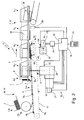
- Fig.1 for the production of adhesive-bound, formed from a book block 1 and an envelope 2 printed products 38 such as books, brochures, magazines, etc., first collected in a collating machine printed products to loose book block 1. Subsequently, the book blocks are bound in a downstream adhesive binding device 3 in the region of the back 4.
- the adhesive binding device 3 has m in a closed path at regular intervals circumferential, driven by a pulling means 5 brackets 6, where the book block 1 for back processing, gluing and attaching the envelope 2 are supplied.
- the traction means 5 is driven by a drive wheel 8, which is connected via a drive shaft 9 with a main drive 10 of the adhesive binding device 3.
- the main drive 10 includes a transfer gear 11 and a main motor 12 that drives the transfer gear 11.
- a handling station 15 essentially formed by a cover feeder 13 and an envelope feeder 14 guides the envelopes 2 in an isochronously controlled manner to the book block 1 by means of a carrier 18 attached to a chain 17 and thus forms one of the last processing stations 37 of the adhesive binding device 3.
- the envelopes 2 are pressed from below to the back 4 of the book block 1 and laterally to the book block 1, the envelopes 2 and / or the book block 1 are coated with adhesive before pressing.
- a measuring device 28 for detecting the mutual position of the envelope 2 and book block 1 along the back 4 is provided.
- the actual values I determined by the measuring device 28 are transmitted to an evaluation and control unit 19 connected to it, compared with these by a desired value S and calculated correction values K. The formation of the correction values K will be explained after the device description.
- the measuring device 28 is arranged after the pressing station 24, ie the penultimate processing station 37.
- the measuring device 28 could also be arranged after the release station 7. This can be in the Area of the measuring station 28 located printed product 38 clearly assign a pairing P of a bracket 6 with a driver 18.
- the envelopes 2 stacked on each other in a magazine 16 of the envelope feeder 13 are separated by the envelope feeder 13 and transferred to the envelope feeder 14.
- This has n carrier 18, which are attached to the revolving chain 17 at regular intervals.
- the chain 17 is driven in a clock-synchronized manner to the clamps 6 by a drive device 20 associated with the envelope feeder 13 and connected to the evaluation and control unit 19.
- the drive device 20 is formed from a superposition gear 22 connected to the transfer gear 11 via a king shaft 31 and an electric motor 21.
- the superposition gear 22 adds, which generated by the superposition gear 22, designed as a servomotor electric motor 21 rotation angle with the rotation angle of the transfer gear 11th
- the electric motor 21 is preferably designed as a rotational angle-controlled stepper motor or servomotor, which is connected to a motor controller 23 connected to the evaluation and control unit 19.
- corrections can be made to the mutual position of the drivers 18, or of the envelopes 2, to the clamps 6 or the book block 1 clamped in the clamps 6. This is done immediately before the merging of the envelopes 2 with the book block 1 by the pressing station 24.
- corrections are based on the determined by means of the measuring device 28 actual position of the envelopes 2 to the book block 1 previously delivered printed products 38th
- the evaluation and control unit 19 If the evaluation and control unit 19 is turned off, it loses control of the position of the driver 18 to the brackets 6. After re-switching the evaluation and control unit 19 this is therefore the position of the driver 18 to the brackets 6 not known, thus first printed products 38 are made with undefined position of the envelopes 2 to the book block 1 until after a measurement of the deviations with the measuring device 28, the deviations are compensated by the evaluation and control unit 19.
- a reference clock 32 is driven via a reference gear 35 such that it triggers an impulse at the reference clock sensor 33 at each machine cycle.
- the main drive 10 is moved to the position in which the reference clock sensor 33 receives a pulse.
- the drive device 20 is moved to that position in which the driver sensor 34 receives a pulse.
- the synchronization can be done with an empty perfect binding device 3, so that the envelopes 2 can already be fed to the book blocks 1 at the correct position in the first printed products 38 to be produced.
- the drive device 20 has a rotational angle-controlled electric motor 21 which drives the chain 17 directly or via a transmission 25 connected therebetween.
- the main drive 10 drives via a reduction gear 26 exclusively the traction means 5 and the brackets 6 at.
- a position sensor resolver 27 is provided on the main motor 12, with which the rotational angle position of the main motor 12 is permanently detectable.
- the electric motor 21 follows the main motor 12 in synchronism.
- the main drive 10 thus constitutes the master drive followed by the drive device 20 as a slave drive.
- Such systems are also known by the term "electrical wave".
- a resolver which is connected to the evaluation and control unit 19 or the motor controller 23.
- a pulse per machine clock is generated in the reference clock sensor 33 by a reference clock, not shown here.
- the synchronization of the driver 18 with the brackets 6 can also be carried out analogously to the description of the first embodiment.
- the following describes a method by which an accurate position of the envelopes 2 to the book blocks 1 in the longitudinal direction of the back 4 is achieved.
- the actual values I continuously determined by the measuring device 28 are compared with a desired value S entered in an operating unit 29 and stored in the evaluation and control unit 19.
- the deviations are assigned to the pairings P of the participating brackets 6 and the driver 18.
- the evaluation and control unit 19 calculates for the relevant combination of a clamp 6 m and a driver 18 n a correction value K mn for a pairing P mn which is stored in a database of the evaluation and control unit 19.
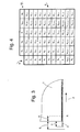
- Fig. 4 shows in tabular form the correction values K 1.1 ... mn associated with the pairings P of brackets 6 1..m and drivers 18 1..n .
- the correction values K 1.1... Mn can be set to any desired value since they are automatically corrected during production. It makes sense, however, to set it to a value that corresponds to the actual value I approximately.
- the adhesive binding device has 3 m staples 6 and the chain 17 n driver 18, the maximum possible number of pairings of staples 6 and drivers 18 results as the product of number m of staples 6 multiplied by the number n of drivers 18.
- Each of these pairings P is in the one computer 30 having or associated with a computer 30 evaluation and control unit 19 associated with at least one memory location in which a previously determined correction value K 11 mn is stored, which becomes effective immediately before the next meeting of bracket 6 and driver 18 of the same pairing P.
- Fig. 3 is the rear portion of a book block 1 with an attached envelope 2 shown.
- the dimension S corresponds to the desired value S, which the envelope 2 is to protrude above the book block 1, and the dimension I to the actual value I, which is measured by the measuring device 28.
- the position of the envelope 2 to the book block 1 therefore has a deviation from SI.
- a pulse within a machine cycle is assumed, which is generated directly or indirectly with the main drive 10, for example a pulse of the reference clock sensor 33.
- the funded with the clip 6 4 book block 1 is supplied with the driver 18 3 an envelope 2.
- the valid for this pairing P 4 3 correction value K 43 is stored in the evaluation and control unit 19.
- the multiplier M can be any value between 0 and 1. With a small multiplier M, the control becomes slower and with a larger multiplier M faster.
- a value of 0.5 is selected for the multiplier M.
- the described method can be used to correct deviations caused by changes in the production conditions as well as longer-term drifts caused by wear of, for example, drive elements designed as a chain.
- the evaluation and control unit 19 is connected to the operating unit 29.
- the use of the method described for the adhesive binder 3 is not limited to this application. It can also be used, for example, for the application of glued envelopes in saddle stitchers in the manufacture of so-called “square backs" or for the attachment of dust covers in dust jacket machines.
Applications Claiming Priority (1)
| Application Number | Priority Date | Filing Date | Title |
|---|---|---|---|
| CH21142010 | 2010-12-17 |
Publications (2)
| Publication Number | Publication Date |
|---|---|
| EP2465697A1 EP2465697A1 (de) | 2012-06-20 |
| EP2465697B1 true EP2465697B1 (de) | 2015-03-25 |
Family
ID=43797546
Family Applications (1)
| Application Number | Title | Priority Date | Filing Date |
|---|---|---|---|
| EP11193332.1A Active EP2465697B1 (de) | 2010-12-17 | 2011-12-13 | Verfahren und Vorrichtung zur Herstellung von klebegebundenen, aus einem Buchblock und einem Umschlag gebildeten Druckerzeugnissen |
Country Status (4)
| Country | Link |
|---|---|
| US (1) | US8662810B2 (zh) |
| EP (1) | EP2465697B1 (zh) |
| JP (1) | JP6360275B2 (zh) |
| CN (1) | CN102529485B (zh) |
Families Citing this family (8)
| Publication number | Priority date | Publication date | Assignee | Title |
|---|---|---|---|---|
| CN103738069B (zh) * | 2013-12-13 | 2015-09-02 | 安徽华印机电股份有限公司 | 搭页机书帖定位装置 |
| CN103753998B (zh) * | 2013-12-21 | 2016-06-08 | 广州向盟机械有限公司 | 一种胶装机 |
| CN107878062B (zh) * | 2017-12-18 | 2023-06-06 | 杭州中冠瀚明科技有限公司 | 胶装机的中空式铣刀机构以及胶装机 |
| CN109385230B (zh) * | 2018-10-23 | 2020-11-20 | 北京市庆全新光印刷有限公司 | 一种书刊印刷的胶装工艺 |
| CN109159562A (zh) * | 2018-10-29 | 2019-01-08 | 刘小成 | 车线本上胶装订机 |
| CN109466204B (zh) * | 2018-11-27 | 2024-03-22 | 大连天泰紫光装订设备有限公司 | 一种胶订机 |
| CN110126504B (zh) * | 2019-03-16 | 2021-06-08 | 广东绿之彩科技股份有限公司 | 图书装订设备 |
| CN114393943B (zh) * | 2022-01-27 | 2023-09-29 | 深圳精密达智能机器有限公司 | 一种新型的胶订机书背加工工艺 |
Family Cites Families (17)
| Publication number | Priority date | Publication date | Assignee | Title |
|---|---|---|---|---|
| CH475098A (de) | 1967-05-25 | 1969-07-15 | Martini Buchbindermaschf | Verfahren und Vorrichtung zum Anlegen der Umschläge an Buchblocks in Klebebindemaschinen |
| CH586115A5 (zh) | 1975-09-09 | 1977-03-31 | Grapha Holding Ag | |
| JPS53125133A (en) * | 1977-04-08 | 1978-11-01 | Komori Printing Mach | Device for supplying covers to bookbinding machine |
| JPS59169898A (ja) * | 1983-03-16 | 1984-09-25 | 株式会社 オ−トスタンプ研究所 | 複写用紙等の丁合機 |
| JP3361744B2 (ja) * | 1998-05-28 | 2003-01-07 | 廣 小林 | 自動化された製本方法及びこれを利用した自動製本機 |
| EP1072436B1 (de) * | 1999-07-22 | 2003-11-05 | Grapha-Holding Ag | Einrichtung für das Anreiben einer Buchdecke an den beleimten Aussenflächen von in einer Buchblockeinhängemaschine in Buchdecken einzuhängenden Buchblocks |
| JP2001096945A (ja) * | 1999-09-28 | 2001-04-10 | Web Tec Kk | 製本における表紙ののり付け装置ならびにその方法 |
| DE10221542A1 (de) | 2002-05-15 | 2003-11-27 | Kolbus Gmbh & Co Kg | Buchbindemaschine |
| JP4346419B2 (ja) * | 2003-11-18 | 2009-10-21 | ホリゾン・インターナショナル株式会社 | 製本機 |
| DE102004021958A1 (de) * | 2004-05-04 | 2005-12-01 | Heidelberger Druckmaschinen Ag | Sammelhefter für Broschuren |
| JP4706519B2 (ja) * | 2006-03-17 | 2011-06-22 | コニカミノルタビジネステクノロジーズ株式会社 | 画像形成システム |
| EP1880863A1 (de) * | 2006-07-19 | 2008-01-23 | Müller Martini Holding AG | Verfahren und Vorrichtung zum Herstellen von aus einem Buchblock und einem Umschlag bestehenden Druckerzeugnissen |
| US8083455B2 (en) * | 2007-02-16 | 2011-12-27 | Quad/Tech, Inc. | Cover applier system |
| DE102007060569A1 (de) * | 2007-12-15 | 2009-06-18 | Kolbus Gmbh & Co. Kg | Vorrichtung zum Zuführen von Buchblocks |
| EP2457738B1 (de) * | 2008-04-30 | 2015-02-11 | Müller Martini Holding AG | Verfahren zum Klebebinden von Buchblocks mit Vorsatzbogen |
| JP5224907B2 (ja) * | 2008-05-28 | 2013-07-03 | ホリゾン・インターナショナル株式会社 | 無線綴じ製本装置 |
| US8517656B2 (en) * | 2010-01-08 | 2013-08-27 | Goss International Americas, Inc. | Cover applier and method of aligning a book image to a cover image |
-
2011
- 2011-12-13 EP EP11193332.1A patent/EP2465697B1/de active Active
- 2011-12-15 US US13/326,841 patent/US8662810B2/en active Active
- 2011-12-16 JP JP2011276509A patent/JP6360275B2/ja active Active
- 2011-12-16 CN CN201110422955.2A patent/CN102529485B/zh active Active
Also Published As
| Publication number | Publication date |
|---|---|
| CN102529485B (zh) | 2015-09-09 |
| US20120155992A1 (en) | 2012-06-21 |
| CN102529485A (zh) | 2012-07-04 |
| JP2012131226A (ja) | 2012-07-12 |
| US8662810B2 (en) | 2014-03-04 |
| EP2465697A1 (de) | 2012-06-20 |
| JP6360275B2 (ja) | 2018-07-18 |
Similar Documents
| Publication | Publication Date | Title |
|---|---|---|
| EP2465697B1 (de) | Verfahren und Vorrichtung zur Herstellung von klebegebundenen, aus einem Buchblock und einem Umschlag gebildeten Druckerzeugnissen | |
| EP1834805B1 (de) | Vorrichtung und Verfahren zum Anpressen eines Umschlages an einen bewegten Bedruckstoffblock | |
| DE202005007012U1 (de) | Buchbindemaschine | |
| EP2636536B1 (de) | Umrüsten einer Fertigungsanlage für die Druckweiterverarbeitung | |
| EP2305485A1 (de) | Verfahren und Vorrichtung zur Herstellung von aus ein- oder mehrblättrigen Druckprodukten sowie eingelegten Beilagen bestehenden Druckerzeugnissen | |
| EP1762525B1 (de) | Einrichtung für das Zusammentragen bzw. Sammeln von Druckprodukten | |
| DE202016008849U1 (de) | Tiefziehverpackungsmaschine | |
| EP2960067B1 (de) | Verfahren zur optimierung der dickeneinstellung eines klebebinders | |
| DE202008002223U1 (de) | Einbanddecken-Aufbringer-System | |
| EP2460749B1 (de) | Verfahren zum Betrieb eines Transportsystems | |
| EP1559573B1 (de) | Verfahren zur Herstellung von Druckerzeugnissen wie Bücher, Broschüren, Zeitschriften oder dgl | |
| EP1918232B1 (de) | Verfahren zur Herstellung von aus mehreren Druckprodukten gebildeten klebegebundenen Druckerzeugnissen und Einrichtung und Vorrichtung zur Durchführung des Verfahrens | |
| EP2657163B1 (de) | Verfahren zum Betrieb einer Fadenheftmaschine | |
| EP1935821A1 (de) | Verfahren zum Bilden von Stapeln aus Druckerzeugnissen, insbesondere Büchern, Zeitschriften, Zeitungen und Broschuren und Einrichtung zu dessen Durchführung | |
| EP0731046A2 (de) | Vorrichtung zur Synchronisation der Zuführung von Bogen | |
| DE102020108483A1 (de) | Buchfertigungsstrasse und Verfahren sowohl zur Herstellung von Einzelbüchern als auch von Kleinst- oder Kleinauflagen von Büchern | |
| EP2080634B1 (de) | Verfahren zum Betreiben einer Buchbindemaschine | |
| EP0358065A2 (de) | Anordnung zur Tabloid-Weiterverarbeitung | |
| EP0806392A2 (de) | Verfahren zum Sammeln von Druckprodukten zu Druckerzeugnissen | |
| DE102011119126A1 (de) | Vorrichtung zum Anlegen eines Umschlags | |
| EP0997421A1 (de) | Vorrichtung zum Sammeln von Druckprodukten | |
| EP3169529B1 (de) | Verfahren zum betreiben einer einrichtung zum herstellen von drucksachen | |
| EP1623945A1 (de) | Vorrichtung zum Zusammentragen flächiger Werkstücke | |
| EP2030801B1 (de) | Verfahren zur Herstellung von aus zusammengetragenen Druckbogen gebildeten klebegebundenen Buchblocks und entsprechende Vorrichtung | |
| DE102014107037B3 (de) | Verfahren, Vorrichtung und Systeme zur Verarbeitung einer Mehrzahl blattförmiger Dokumente |
Legal Events
| Date | Code | Title | Description |
|---|---|---|---|
| PUAI | Public reference made under article 153(3) epc to a published international application that has entered the european phase |
Free format text: ORIGINAL CODE: 0009012 |
|
| AK | Designated contracting states |
Kind code of ref document: A1 Designated state(s): AL AT BE BG CH CY CZ DE DK EE ES FI FR GB GR HR HU IE IS IT LI LT LU LV MC MK MT NL NO PL PT RO RS SE SI SK SM TR |
|
| AX | Request for extension of the european patent |
Extension state: BA ME |
|
| 17P | Request for examination filed |
Effective date: 20121115 |
|
| GRAP | Despatch of communication of intention to grant a patent |
Free format text: ORIGINAL CODE: EPIDOSNIGR1 |
|
| RIC1 | Information provided on ipc code assigned before grant |
Ipc: B42C 11/04 20060101AFI20140717BHEP |
|
| INTG | Intention to grant announced |
Effective date: 20140820 |
|
| GRAP | Despatch of communication of intention to grant a patent |
Free format text: ORIGINAL CODE: EPIDOSNIGR1 |
|
| GRAS | Grant fee paid |
Free format text: ORIGINAL CODE: EPIDOSNIGR3 |
|
| INTG | Intention to grant announced |
Effective date: 20141125 |
|
| GRAA | (expected) grant |
Free format text: ORIGINAL CODE: 0009210 |
|
| AK | Designated contracting states |
Kind code of ref document: B1 Designated state(s): AL AT BE BG CH CY CZ DE DK EE ES FI FR GB GR HR HU IE IS IT LI LT LU LV MC MK MT NL NO PL PT RO RS SE SI SK SM TR |
|
| REG | Reference to a national code |
Ref country code: GB Ref legal event code: FG4D Free format text: NOT ENGLISH |
|
| REG | Reference to a national code |
Ref country code: CH Ref legal event code: EP |
|
| REG | Reference to a national code |
Ref country code: IE Ref legal event code: FG4D Free format text: LANGUAGE OF EP DOCUMENT: GERMAN |
|
| REG | Reference to a national code |
Ref country code: DE Ref legal event code: R096 Ref document number: 502011006364 Country of ref document: DE Effective date: 20150507 |
|
| REG | Reference to a national code |
Ref country code: AT Ref legal event code: REF Ref document number: 717634 Country of ref document: AT Kind code of ref document: T Effective date: 20150515 |
|
| PG25 | Lapsed in a contracting state [announced via postgrant information from national office to epo] |
Ref country code: SE Free format text: LAPSE BECAUSE OF FAILURE TO SUBMIT A TRANSLATION OF THE DESCRIPTION OR TO PAY THE FEE WITHIN THE PRESCRIBED TIME-LIMIT Effective date: 20150325 Ref country code: HR Free format text: LAPSE BECAUSE OF FAILURE TO SUBMIT A TRANSLATION OF THE DESCRIPTION OR TO PAY THE FEE WITHIN THE PRESCRIBED TIME-LIMIT Effective date: 20150325 Ref country code: LT Free format text: LAPSE BECAUSE OF FAILURE TO SUBMIT A TRANSLATION OF THE DESCRIPTION OR TO PAY THE FEE WITHIN THE PRESCRIBED TIME-LIMIT Effective date: 20150325 Ref country code: FI Free format text: LAPSE BECAUSE OF FAILURE TO SUBMIT A TRANSLATION OF THE DESCRIPTION OR TO PAY THE FEE WITHIN THE PRESCRIBED TIME-LIMIT Effective date: 20150325 |
|
| REG | Reference to a national code |
Ref country code: LT Ref legal event code: MG4D |
|
| PG25 | Lapsed in a contracting state [announced via postgrant information from national office to epo] |
Ref country code: RS Free format text: LAPSE BECAUSE OF FAILURE TO SUBMIT A TRANSLATION OF THE DESCRIPTION OR TO PAY THE FEE WITHIN THE PRESCRIBED TIME-LIMIT Effective date: 20150325 Ref country code: GR Free format text: LAPSE BECAUSE OF FAILURE TO SUBMIT A TRANSLATION OF THE DESCRIPTION OR TO PAY THE FEE WITHIN THE PRESCRIBED TIME-LIMIT Effective date: 20150626 Ref country code: LV Free format text: LAPSE BECAUSE OF FAILURE TO SUBMIT A TRANSLATION OF THE DESCRIPTION OR TO PAY THE FEE WITHIN THE PRESCRIBED TIME-LIMIT Effective date: 20150325 |
|
| PG25 | Lapsed in a contracting state [announced via postgrant information from national office to epo] |
Ref country code: NL Free format text: LAPSE BECAUSE OF FAILURE TO SUBMIT A TRANSLATION OF THE DESCRIPTION OR TO PAY THE FEE WITHIN THE PRESCRIBED TIME-LIMIT Effective date: 20150325 |
|
| PG25 | Lapsed in a contracting state [announced via postgrant information from national office to epo] |
Ref country code: EE Free format text: LAPSE BECAUSE OF FAILURE TO SUBMIT A TRANSLATION OF THE DESCRIPTION OR TO PAY THE FEE WITHIN THE PRESCRIBED TIME-LIMIT Effective date: 20150325 Ref country code: CZ Free format text: LAPSE BECAUSE OF FAILURE TO SUBMIT A TRANSLATION OF THE DESCRIPTION OR TO PAY THE FEE WITHIN THE PRESCRIBED TIME-LIMIT Effective date: 20150325 Ref country code: RO Free format text: LAPSE BECAUSE OF FAILURE TO SUBMIT A TRANSLATION OF THE DESCRIPTION OR TO PAY THE FEE WITHIN THE PRESCRIBED TIME-LIMIT Effective date: 20150325 Ref country code: PT Free format text: LAPSE BECAUSE OF FAILURE TO SUBMIT A TRANSLATION OF THE DESCRIPTION OR TO PAY THE FEE WITHIN THE PRESCRIBED TIME-LIMIT Effective date: 20150727 Ref country code: SK Free format text: LAPSE BECAUSE OF FAILURE TO SUBMIT A TRANSLATION OF THE DESCRIPTION OR TO PAY THE FEE WITHIN THE PRESCRIBED TIME-LIMIT Effective date: 20150325 Ref country code: ES Free format text: LAPSE BECAUSE OF FAILURE TO SUBMIT A TRANSLATION OF THE DESCRIPTION OR TO PAY THE FEE WITHIN THE PRESCRIBED TIME-LIMIT Effective date: 20150325 |
|
| PG25 | Lapsed in a contracting state [announced via postgrant information from national office to epo] |
Ref country code: IS Free format text: LAPSE BECAUSE OF FAILURE TO SUBMIT A TRANSLATION OF THE DESCRIPTION OR TO PAY THE FEE WITHIN THE PRESCRIBED TIME-LIMIT Effective date: 20150725 Ref country code: PL Free format text: LAPSE BECAUSE OF FAILURE TO SUBMIT A TRANSLATION OF THE DESCRIPTION OR TO PAY THE FEE WITHIN THE PRESCRIBED TIME-LIMIT Effective date: 20150325 |
|
| REG | Reference to a national code |
Ref country code: DE Ref legal event code: R097 Ref document number: 502011006364 Country of ref document: DE |
|
| PG25 | Lapsed in a contracting state [announced via postgrant information from national office to epo] |
Ref country code: DK Free format text: LAPSE BECAUSE OF FAILURE TO SUBMIT A TRANSLATION OF THE DESCRIPTION OR TO PAY THE FEE WITHIN THE PRESCRIBED TIME-LIMIT Effective date: 20150325 |
|
| PLBE | No opposition filed within time limit |
Free format text: ORIGINAL CODE: 0009261 |
|
| STAA | Information on the status of an ep patent application or granted ep patent |
Free format text: STATUS: NO OPPOSITION FILED WITHIN TIME LIMIT |
|
| 26N | No opposition filed |
Effective date: 20160105 |
|
| PG25 | Lapsed in a contracting state [announced via postgrant information from national office to epo] |
Ref country code: SI Free format text: LAPSE BECAUSE OF FAILURE TO SUBMIT A TRANSLATION OF THE DESCRIPTION OR TO PAY THE FEE WITHIN THE PRESCRIBED TIME-LIMIT Effective date: 20150325 Ref country code: BE Free format text: LAPSE BECAUSE OF NON-PAYMENT OF DUE FEES Effective date: 20151231 |
|
| PG25 | Lapsed in a contracting state [announced via postgrant information from national office to epo] |
Ref country code: MC Free format text: LAPSE BECAUSE OF FAILURE TO SUBMIT A TRANSLATION OF THE DESCRIPTION OR TO PAY THE FEE WITHIN THE PRESCRIBED TIME-LIMIT Effective date: 20150325 Ref country code: LU Free format text: LAPSE BECAUSE OF FAILURE TO SUBMIT A TRANSLATION OF THE DESCRIPTION OR TO PAY THE FEE WITHIN THE PRESCRIBED TIME-LIMIT Effective date: 20151213 |
|
| REG | Reference to a national code |
Ref country code: IE Ref legal event code: MM4A |
|
| REG | Reference to a national code |
Ref country code: FR Ref legal event code: ST Effective date: 20160831 |
|
| PG25 | Lapsed in a contracting state [announced via postgrant information from national office to epo] |
Ref country code: IE Free format text: LAPSE BECAUSE OF NON-PAYMENT OF DUE FEES Effective date: 20151213 |
|
| PG25 | Lapsed in a contracting state [announced via postgrant information from national office to epo] |
Ref country code: FR Free format text: LAPSE BECAUSE OF NON-PAYMENT OF DUE FEES Effective date: 20151231 |
|
| PG25 | Lapsed in a contracting state [announced via postgrant information from national office to epo] |
Ref country code: HU Free format text: LAPSE BECAUSE OF FAILURE TO SUBMIT A TRANSLATION OF THE DESCRIPTION OR TO PAY THE FEE WITHIN THE PRESCRIBED TIME-LIMIT; INVALID AB INITIO Effective date: 20111213 Ref country code: BG Free format text: LAPSE BECAUSE OF FAILURE TO SUBMIT A TRANSLATION OF THE DESCRIPTION OR TO PAY THE FEE WITHIN THE PRESCRIBED TIME-LIMIT Effective date: 20150325 Ref country code: NO Free format text: LAPSE BECAUSE OF FAILURE TO SUBMIT A TRANSLATION OF THE DESCRIPTION OR TO PAY THE FEE WITHIN THE PRESCRIBED TIME-LIMIT Effective date: 20150625 Ref country code: SM Free format text: LAPSE BECAUSE OF FAILURE TO SUBMIT A TRANSLATION OF THE DESCRIPTION OR TO PAY THE FEE WITHIN THE PRESCRIBED TIME-LIMIT Effective date: 20150325 |
|
| PG25 | Lapsed in a contracting state [announced via postgrant information from national office to epo] |
Ref country code: CY Free format text: LAPSE BECAUSE OF FAILURE TO SUBMIT A TRANSLATION OF THE DESCRIPTION OR TO PAY THE FEE WITHIN THE PRESCRIBED TIME-LIMIT Effective date: 20150325 |
|
| PG25 | Lapsed in a contracting state [announced via postgrant information from national office to epo] |
Ref country code: TR Free format text: LAPSE BECAUSE OF FAILURE TO SUBMIT A TRANSLATION OF THE DESCRIPTION OR TO PAY THE FEE WITHIN THE PRESCRIBED TIME-LIMIT Effective date: 20150325 Ref country code: MT Free format text: LAPSE BECAUSE OF FAILURE TO SUBMIT A TRANSLATION OF THE DESCRIPTION OR TO PAY THE FEE WITHIN THE PRESCRIBED TIME-LIMIT Effective date: 20150325 |
|
| REG | Reference to a national code |
Ref country code: AT Ref legal event code: MM01 Ref document number: 717634 Country of ref document: AT Kind code of ref document: T Effective date: 20161213 |
|
| PG25 | Lapsed in a contracting state [announced via postgrant information from national office to epo] |
Ref country code: AT Free format text: LAPSE BECAUSE OF NON-PAYMENT OF DUE FEES Effective date: 20161213 |
|
| PG25 | Lapsed in a contracting state [announced via postgrant information from national office to epo] |
Ref country code: MK Free format text: LAPSE BECAUSE OF FAILURE TO SUBMIT A TRANSLATION OF THE DESCRIPTION OR TO PAY THE FEE WITHIN THE PRESCRIBED TIME-LIMIT Effective date: 20150325 |
|
| PG25 | Lapsed in a contracting state [announced via postgrant information from national office to epo] |
Ref country code: AL Free format text: LAPSE BECAUSE OF FAILURE TO SUBMIT A TRANSLATION OF THE DESCRIPTION OR TO PAY THE FEE WITHIN THE PRESCRIBED TIME-LIMIT Effective date: 20150325 |
|
| PGFP | Annual fee paid to national office [announced via postgrant information from national office to epo] |
Ref country code: CH Payment date: 20190322 Year of fee payment: 8 |
|
| PGFP | Annual fee paid to national office [announced via postgrant information from national office to epo] |
Ref country code: GB Payment date: 20191220 Year of fee payment: 9 |
|
| REG | Reference to a national code |
Ref country code: CH Ref legal event code: PL |
|
| PG25 | Lapsed in a contracting state [announced via postgrant information from national office to epo] |
Ref country code: CH Free format text: LAPSE BECAUSE OF NON-PAYMENT OF DUE FEES Effective date: 20191231 Ref country code: LI Free format text: LAPSE BECAUSE OF NON-PAYMENT OF DUE FEES Effective date: 20191231 |
|
| GBPC | Gb: european patent ceased through non-payment of renewal fee |
Effective date: 20201213 |
|
| PG25 | Lapsed in a contracting state [announced via postgrant information from national office to epo] |
Ref country code: GB Free format text: LAPSE BECAUSE OF NON-PAYMENT OF DUE FEES Effective date: 20201213 |
|
| PGFP | Annual fee paid to national office [announced via postgrant information from national office to epo] |
Ref country code: IT Payment date: 20231227 Year of fee payment: 13 |
|
| PGFP | Annual fee paid to national office [announced via postgrant information from national office to epo] |
Ref country code: DE Payment date: 20231221 Year of fee payment: 13 |