EP2462002B1 - Kraftfahrzeugsitz und verfahren zur überführung einer rückenlehne von der gebrauchs- in eine verstauposition - Google Patents
Kraftfahrzeugsitz und verfahren zur überführung einer rückenlehne von der gebrauchs- in eine verstauposition Download PDFInfo
- Publication number
- EP2462002B1 EP2462002B1 EP10744871.4A EP10744871A EP2462002B1 EP 2462002 B1 EP2462002 B1 EP 2462002B1 EP 10744871 A EP10744871 A EP 10744871A EP 2462002 B1 EP2462002 B1 EP 2462002B1
- Authority
- EP
- European Patent Office
- Prior art keywords
- seatback
- component
- relative
- locking
- rotational
- Prior art date
- Legal status (The legal status is an assumption and is not a legal conclusion. Google has not performed a legal analysis and makes no representation as to the accuracy of the status listed.)
- Not-in-force
Links
- 238000000034 method Methods 0.000 title claims description 17
- 230000008878 coupling Effects 0.000 claims 1
- 238000010168 coupling process Methods 0.000 claims 1
- 238000005859 coupling reaction Methods 0.000 claims 1
- 210000000078 claw Anatomy 0.000 description 8
- 230000005540 biological transmission Effects 0.000 description 4
- 230000000903 blocking effect Effects 0.000 description 2
- 238000006073 displacement reaction Methods 0.000 description 2
- 230000002349 favourable effect Effects 0.000 description 2
- 238000004904 shortening Methods 0.000 description 1
Images


Classifications
-
- B—PERFORMING OPERATIONS; TRANSPORTING
- B60—VEHICLES IN GENERAL
- B60N—SEATS SPECIALLY ADAPTED FOR VEHICLES; VEHICLE PASSENGER ACCOMMODATION NOT OTHERWISE PROVIDED FOR
- B60N2/00—Seats specially adapted for vehicles; Arrangement or mounting of seats in vehicles
- B60N2/02—Seats specially adapted for vehicles; Arrangement or mounting of seats in vehicles the seat or part thereof being movable, e.g. adjustable
- B60N2/22—Seats specially adapted for vehicles; Arrangement or mounting of seats in vehicles the seat or part thereof being movable, e.g. adjustable the back-rest being adjustable
-
- B—PERFORMING OPERATIONS; TRANSPORTING
- B60—VEHICLES IN GENERAL
- B60N—SEATS SPECIALLY ADAPTED FOR VEHICLES; VEHICLE PASSENGER ACCOMMODATION NOT OTHERWISE PROVIDED FOR
- B60N2/00—Seats specially adapted for vehicles; Arrangement or mounting of seats in vehicles
- B60N2/02—Seats specially adapted for vehicles; Arrangement or mounting of seats in vehicles the seat or part thereof being movable, e.g. adjustable
- B60N2/20—Seats specially adapted for vehicles; Arrangement or mounting of seats in vehicles the seat or part thereof being movable, e.g. adjustable the back-rest being tiltable, e.g. to permit easy access
- B60N2/206—Seats specially adapted for vehicles; Arrangement or mounting of seats in vehicles the seat or part thereof being movable, e.g. adjustable the back-rest being tiltable, e.g. to permit easy access to a position in which it can be used as a support for objects, e.g. as a tray
-
- B—PERFORMING OPERATIONS; TRANSPORTING
- B60—VEHICLES IN GENERAL
- B60N—SEATS SPECIALLY ADAPTED FOR VEHICLES; VEHICLE PASSENGER ACCOMMODATION NOT OTHERWISE PROVIDED FOR
- B60N2/00—Seats specially adapted for vehicles; Arrangement or mounting of seats in vehicles
- B60N2/02—Seats specially adapted for vehicles; Arrangement or mounting of seats in vehicles the seat or part thereof being movable, e.g. adjustable
- B60N2/20—Seats specially adapted for vehicles; Arrangement or mounting of seats in vehicles the seat or part thereof being movable, e.g. adjustable the back-rest being tiltable, e.g. to permit easy access
-
- B—PERFORMING OPERATIONS; TRANSPORTING
- B60—VEHICLES IN GENERAL
- B60N—SEATS SPECIALLY ADAPTED FOR VEHICLES; VEHICLE PASSENGER ACCOMMODATION NOT OTHERWISE PROVIDED FOR
- B60N2/00—Seats specially adapted for vehicles; Arrangement or mounting of seats in vehicles
- B60N2/02—Seats specially adapted for vehicles; Arrangement or mounting of seats in vehicles the seat or part thereof being movable, e.g. adjustable
- B60N2/22—Seats specially adapted for vehicles; Arrangement or mounting of seats in vehicles the seat or part thereof being movable, e.g. adjustable the back-rest being adjustable
- B60N2/2222—Seats specially adapted for vehicles; Arrangement or mounting of seats in vehicles the seat or part thereof being movable, e.g. adjustable the back-rest being adjustable the back-rest having two or more parts
-
- B—PERFORMING OPERATIONS; TRANSPORTING
- B60—VEHICLES IN GENERAL
- B60N—SEATS SPECIALLY ADAPTED FOR VEHICLES; VEHICLE PASSENGER ACCOMMODATION NOT OTHERWISE PROVIDED FOR
- B60N2/00—Seats specially adapted for vehicles; Arrangement or mounting of seats in vehicles
- B60N2/02—Seats specially adapted for vehicles; Arrangement or mounting of seats in vehicles the seat or part thereof being movable, e.g. adjustable
- B60N2/22—Seats specially adapted for vehicles; Arrangement or mounting of seats in vehicles the seat or part thereof being movable, e.g. adjustable the back-rest being adjustable
- B60N2/235—Seats specially adapted for vehicles; Arrangement or mounting of seats in vehicles the seat or part thereof being movable, e.g. adjustable the back-rest being adjustable by gear-pawl type mechanisms
- B60N2/2352—Seats specially adapted for vehicles; Arrangement or mounting of seats in vehicles the seat or part thereof being movable, e.g. adjustable the back-rest being adjustable by gear-pawl type mechanisms with external pawls
-
- B—PERFORMING OPERATIONS; TRANSPORTING
- B60—VEHICLES IN GENERAL
- B60N—SEATS SPECIALLY ADAPTED FOR VEHICLES; VEHICLE PASSENGER ACCOMMODATION NOT OTHERWISE PROVIDED FOR
- B60N2205/00—General mechanical or structural details
- B60N2205/30—Seat or seat parts characterised by comprising plural parts or pieces
Definitions
- the invention relates to a motor vehicle seat, in particular a rear seat for rear seats of motor vehicles. Furthermore, the invention relates to a method for displacement of a first and a second components relative to a base part, wherein the first and the second component are connected to each other by a first rotating means and the second component and the base part by a second rotating means.
- the invention has for its object to provide a method for folding a backrest of the use in the stowed position and a new, foldable vehicle seat, the vehicle seat is simple and without significant prior knowledge of the user to use and he in the folded state requires little space claimed.
- the method according to the invention relates to the displacement of a backrest, the first component, relative to a seat part, the base part, from a use position in which the backrest is provided substantially perpendicular to the seat part, preferably via a so-called easy entry known to the person skilled in the art -Stellung, in a stowed position, in which the backrest is provided substantially parallel to the seat part.
- first and second rotating means in particular rotation axes provided, which are preferably arranged parallel to each other.
- the first and second rotation means are automatically locked and unlocked relative to the base part relative to the second component and / or second component as a function of at least one position of the first component.
- the first component namely the backrest
- the second component can be displaced relative to the second component, in particular rotated through an angle, the second component remaining locked relative to the base part, for example the seat part, in a first position.
- This function is particularly important for comfort adjustment.
- the angle of attack of the backrest can be adjusted around its vertical position without the lock between the second component and the seat part is released.
- the second rotating means Upon rotation of the first component, namely the backrest, beyond a certain angle, the second rotating means is automatically unlocked and / or the first component is brought into abutment with a stop provided on the second component. This function allows the backrest to be transferred to an easy-entry position.
- a locking means of the first component is automatically brought into a lockable position, i. the locking means could lock the first component relative to the second component, but has not yet locked.
- a locking means of the second component relative to the base part is also automatically brought into a lockable, second position, preferably simultaneously with the locking means of the first component, i. also this locking means could lock the second component relative to the base part, but has not yet locked.
- both parts are automatically locked in their respective position after the component has reached its end position. This position is then, for example, the stowage of the backrest parallel to the seat part.
- the locking is effected by a latching means, in particular a latching pawl.
- the second component in particular after it has been moved to its second position, for example, the stowed position of the backrest, must be unlocked manually or by motor.
- the first component is automatically shortened or extended during a movement of the first component and the second component relative to one another and / or during a movement of the second component relative to the base part.
- the first component is the backrest and / or the base part of the seat part of a vehicle seat.
- Another object is a vehicle seat according to claim 11. Particularly preferably, this agent moves purely translationally.
- the statements made for the method according to the invention apply equally to the vehicle seat according to the invention and vice versa.
- the vehicle seat preferably has an upper fitting, which is pivotable about an upper horizontal axis of rotation, to which the backrest is generally connected and which can be releasably locked by means of an upper locking mechanism.
- the vehicle seat further comprises a second component, an intermediate part, which is preferably pivotally connected about a lower horizontal axis to a lower fitting and is preferably releasably lockable via a lower locking mechanism.
- the under fitting is usually connected to a seat part.
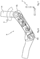
- FIG. 1 shows components of the inventively designed kinematics K of the vehicle seat, in a schematic exploded view.
- the kinematics K comprises a Lehnenschwenkgelenk GL for rotation of the backrest co-rotating with the backrest fitting 10 about an upper axis of rotation.
- the Lehnenschwenkgelenk GL is mechanically coupled to a pull arm 2 so that a rotational movement of the Lehenschwenkgelenks GL is transferable to the pull arm 2.
- the kinematics K further comprises a release member 3, which is in operative connection with the Lehnenschwenkgelenk GL via the Switzerlandarm 2..
- a lower pivot joint GU is non-rotatably connected to a fixed relative to the vehicle body lower fitting 40 to which an example in FIG. 3 represented seat part 4 is mounted.
- the kinematics K further comprises a lower locking unit VU for releasably locking the lower pivot joint GU.
- the locking unit VU in turn comprises a release arm 30, a locking cam 31 and a locking claw 32.
- a sliding strut 5 is provided with a guide slot which serves to guide the release arm 30.
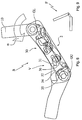
- FIG. 2 shows a schematic sectional view of the basic structure B of the vehicle seat F in a favorable for the vehicle occupant for driving position of use.
- the base structure B includes the backrest fitting 10, which is connected via the Lehnenschwenkgelenk GL hinged to an intermediate part 6.
- the intermediate part 6 is articulated via the lower pivot joint GU, about a lower axis of rotation rotatably on the lower fitting 40.
- the base structure B has an upper locking device for releasably locking the Lehnenschwenkgelenkes GL and a lower locking device V for releasably locking the lower pivot joint GU.
- the Lehnenschwenkgelenk GL is unlocked in this convenient for a vehicle occupant to drive use position of the base structure B, while the lower pivot joint GU is locked.
- the backrest can thus be changed for the comfort adjustment in its inclination angle ⁇ .
- a control slot 20 in the pulling arm 2 serves for the movable guidance of the release member and thereby ultimately allows the pivoting of the backrest fitting 10 within a certain pivoting range for the comfort adjustment of the backrest 1, without being acted upon in this comfort adjustment to the upper locking device or on the lower locking device V.
- the locking cam 31 abuts on a stop lug 33 of the locking claw 32 and thereby holds the locking claw 32 in a position in which a provided on the locking claw 32 first gear 34 with one with the lower Swivel joint GU operatively connected second toothing 35 cooperates, so as ultimately to lock the lower pivot joint GU.
- FIG. 3 shows in a highly schematic representation of a vehicle seat F in a seat-use position, the in FIG. 2 shown use position of the base structure B corresponds.
- the vehicle seat F has a seat part 4 and the backrest 1 connected to the seat part 4 via the intermediate part 6, which rotates together with the backrest fitting 10.
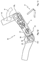
- FIG. 4 shows the basic structure B of FIG. 2 with respect to the FIG. 2 slightly, to the inclination angle ⁇ to the front folded backrest fitting 10.
- the backrest pivot joint GL is still unlocked, while the lower pivot joint GU is still locked.
- FIG. 5 shows in a highly schematic representation of the vehicle seat F in a sitting position, the in FIG. 4 shown position of the base structure B corresponds.
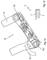
- FIG. 6 shows the basic structure B of Figure 4 with further (greater inclination angle ⁇ ) vorgeklapptem backrest fitting 10.
- the Lehnenschwenkgelenk GL is still unlocked, while the lower pivot joint GU is still locked.
- FIG. 7 shows in a highly schematic representation of the vehicle seat F in a sitting position, the in FIG. 6 shown position of the base structure B corresponds.
- FIG. 8 shows the basic structure B of FIG. 6 From this position of the backrest fitting 10 engages the standing with the Lehnenschwenkgelenk in operative connection pulling arm 2 on the release member, which in turn pushes a provided on release arm 30 pin in the guide slot of the slide strut.
- the release arm 30 begins to act on the lower locking device V such that the locking cam 31 dips into a blocking recess 36 provided on the locking claw 32, whereupon the locking claw 32 can move backwards, away from the lower pivot joint GU, and thus the first Gearing 34 begins to move away from the area of action of the second gearing 35 to thereby transfer the lower pivot joint GU from the locked state to the unlocked state.
- FIG. 9 shows the vehicle seat F in one of the in FIG. 8 shown position of the base structure B corresponding seating position, in a highly schematic representation.
- FIG. 10 shows the basic structure B of FIG. 8 with still further (again larger inclination angle ⁇ ) vorgeklapptem backrest fitting 10.
- the locking cam 31 is even deeper in the locking recess 36 penetrated, whereby the locking claw 32 could retreat further to the rear.
- FIG. 11 shows the vehicle seat F in one of the in FIG. 10 shown position of the basic structure B corresponding seat division, in a highly schematic representation.
- FIG. 12 shows the basic structure B of FIG. 10
- the locking cam 31 is now completely immersed in the locking recess 36, so that the locking claw 32 could retreat so far to the rear, that the first gear 34 and the second gear 35 now out of engagement with even further (even greater angle of inclination ⁇ ) vorgeklapptem backrest fitting with each other and thus the lower pivot joint GU is unlocked.
- the backrest pivot joint GL is still held in the unlocked state by a slider, the backrest fitting 10 is now in a ready-to-lock position ready for locking.
- the intermediate part 6 rotates with the backrest fitting 10 about the lower axis of rotation.
- FIG. 13 shows in a highly schematic representation of the vehicle seat F in a sitting position, the in FIG. 12 shown position of the base structure B corresponds.
- FIG. 14 shows the basic structure B of Figure 12
- the lower pivot joint GU initially remains in the unlocked state until it is transferred into a second locking position (change in the angle ⁇ ) when the backrest movement continues.
- the lower locking device V Before reaching this second locking position, however, on the one hand the lower locking device V is first brought into a ready-to-lock position as a result of the backrest movement and, on the other hand, the rotation of the intermediate part 6 about the lower rotational axis is limited by a second stop stop.
- the kinematics K is designed so that the backrest pivot joint GL and the lower pivot joint GU are locked automatically by their respective associated locking devices only after reaching the second stop stop.
- the coupled to the relative movement of the lower fitting 40 with respect to the intermediate part slider is moved back, after which the Lehnenschwenkgelenk GL begins to rotate into a locked position.
- the backrest fitting 10 is now in contact with a first stop stop, so that further movement of the backrest fitting 10 and thus the backrest 1 is blocked to the front.
- FIG. 15 shows in a highly schematic representation of the vehicle seat F in a sitting position, the in FIG. 14 shown position of the base structure B corresponds.
- FIG. 16 shows the basic structure B of Fig. 14 with even further (even greater inclination angle ⁇ ) vorgeklapptem backrest fitting 10. The slider was moved back further and the Lehnenschwenkgelenk GL continues to rotate to its locked position.
- FIG. 17 shows in a highly schematic representation of the vehicle seat F in one of in FIG. 16 shown position of the base structure B corresponding seat division.
- FIG. 18 shows the basic structure B of FIG. 16
- the backrest pivot joint GL and the lower pivot joint GU are now each latched in a locked position.
- FIG. 19 shows in a highly schematic representation of the vehicle seat F in a sitting position, the in FIG. 18 shown end position of the basic structure corresponds.
- the locked backrest 1 is now arranged approximately horizontally over the seat part 4.
- the front of the seat back 1 and the top of the seat part 4 face each other.
- FIG. 20 a preferred or an additional separate object of the present invention is shown, in which the backrest 1 is shortened when folding from the use position to the stowed position or vice versa, is extended.
- a power transmission means 8 here a toothed belt, driven, the force or torque directly or indirectly to a transmission 9, here a bevel gear. transmits, which drives the length adjustment of the backrest, 1.
Landscapes
- Engineering & Computer Science (AREA)
- Aviation & Aerospace Engineering (AREA)
- Transportation (AREA)
- Mechanical Engineering (AREA)
- Seats For Vehicles (AREA)
- Chairs For Special Purposes, Such As Reclining Chairs (AREA)
Applications Claiming Priority (3)
| Application Number | Priority Date | Filing Date | Title |
|---|---|---|---|
| DE102009036138 | 2009-08-05 | ||
| DE102010023765.5A DE102010023765B4 (de) | 2009-08-05 | 2010-06-15 | Verfahren zur Überführung einer Rückenlehne von der Gebrauchs- in eine Verstaustellung und Kraftfahrzeugsitz |
| PCT/EP2010/004667 WO2011015315A1 (de) | 2009-08-05 | 2010-07-30 | Kraftfahrzeugsitz und verfahren zur überführung einer rückenlehne von der gebrauchs- in eine verstauposition |
Publications (2)
| Publication Number | Publication Date |
|---|---|
| EP2462002A1 EP2462002A1 (de) | 2012-06-13 |
| EP2462002B1 true EP2462002B1 (de) | 2016-09-28 |
Family
ID=43448412
Family Applications (1)
| Application Number | Title | Priority Date | Filing Date |
|---|---|---|---|
| EP10744871.4A Not-in-force EP2462002B1 (de) | 2009-08-05 | 2010-07-30 | Kraftfahrzeugsitz und verfahren zur überführung einer rückenlehne von der gebrauchs- in eine verstauposition |
Country Status (8)
Families Citing this family (9)
| Publication number | Priority date | Publication date | Assignee | Title |
|---|---|---|---|---|
| DE102012012983B4 (de) * | 2012-06-29 | 2014-04-24 | Isringhausen Gmbh & Co. Kg | Fahrzeugsitz mit Rückenlehnenneigungseinstellung sowie Schulteranpassung |
| US9085252B2 (en) * | 2013-05-02 | 2015-07-21 | GM Global Technology Operations LLC | Vehicle seat assembly with dual locked seating positions and method of adjusting a vehicle seat |
| CN105722721B (zh) * | 2013-09-18 | 2018-03-20 | 提爱思科技股份有限公司 | 车辆座椅 |
| US9622593B2 (en) * | 2014-01-14 | 2017-04-18 | Artsana Usa, Inc. | Pinch free folding lock |
| US10149552B2 (en) | 2015-01-06 | 2018-12-11 | Artsana Usa, Inc. | Pinch free folding lock |
| JP6871506B2 (ja) | 2017-02-08 | 2021-05-12 | テイ・エス テック株式会社 | 中折れシートバック及び中折れシートバックを有する車両用シート |
| CN110920738B (zh) * | 2018-09-19 | 2022-07-26 | 明门瑞士股份有限公司 | 转动安全机构及具有该机构的座椅 |
| US11833937B2 (en) * | 2021-09-08 | 2023-12-05 | Faurecia Automotive Seating, Llc | Occupant support |
| CN114290967B (zh) * | 2022-01-10 | 2023-07-04 | 浙江吉利控股集团有限公司 | 座椅骨架、座椅及车辆 |
Citations (1)
| Publication number | Priority date | Publication date | Assignee | Title |
|---|---|---|---|---|
| US1663898A (en) * | 1924-09-18 | 1928-03-27 | Frank C Bitzenburger | Yieldable back support for seats |
Family Cites Families (11)
| Publication number | Priority date | Publication date | Assignee | Title |
|---|---|---|---|---|
| ES2079443T3 (es) | 1989-07-28 | 1996-01-16 | Fuji Kiko Kk | Asiento para vehiculo automovil con mecanismo de entrada. |
| CN2093112U (zh) * | 1991-03-23 | 1992-01-15 | 施克礼 | 双关节汽车座椅调角器 |
| KR100291936B1 (ko) * | 1997-08-30 | 2001-11-26 | 이계안 | 승합차량용좌석의리클라이너닝과회전연동장치 |
| FR2799420B1 (fr) * | 1999-10-08 | 2002-01-04 | Faure Bertrand Equipements Sa | Siege de vehicule |
| US6513876B1 (en) * | 2000-11-17 | 2003-02-04 | Gayle D. Agler | Multiple function boat seat |
| FR2825955B1 (fr) * | 2001-06-15 | 2005-10-14 | Faurecia Automotive Seating Ca | Mecanisme d'articulation de siege de vehicule ameliore |
| DE10132701B4 (de) * | 2001-07-05 | 2008-11-06 | Keiper Gmbh & Co.Kg | Beschlag für einen Fahrzeugsitz |
| DE10149858C2 (de) * | 2001-10-10 | 2003-10-02 | Johnson Controls Gmbh | Fahrzeugsitz mit schwenkbarer Rückenlehne |
| KR100461102B1 (ko) * | 2002-08-08 | 2004-12-13 | 현대자동차주식회사 | 차량용 리어시트의 리클라이닝 장치 |
| FR2899161B1 (fr) * | 2006-03-30 | 2009-03-20 | Renault Sas | Siege de vehicule automobile repliable |
| CN101883697B (zh) * | 2007-12-03 | 2012-08-15 | 丰田纺织株式会社 | 车辆用座椅 |
-
2010
- 2010-06-15 DE DE102010023765.5A patent/DE102010023765B4/de not_active Expired - Fee Related
- 2010-07-30 US US13/387,132 patent/US8974001B2/en active Active
- 2010-07-30 IN IN993DEN2012 patent/IN2012DN00993A/en unknown
- 2010-07-30 KR KR1020127005873A patent/KR101345678B1/ko not_active Expired - Fee Related
- 2010-07-30 EP EP10744871.4A patent/EP2462002B1/de not_active Not-in-force
- 2010-07-30 CN CN201080042798.6A patent/CN102548793B/zh not_active Expired - Fee Related
- 2010-07-30 JP JP2012523231A patent/JP5674784B2/ja not_active Expired - Fee Related
- 2010-07-30 WO PCT/EP2010/004667 patent/WO2011015315A1/de active Application Filing
Patent Citations (1)
| Publication number | Priority date | Publication date | Assignee | Title |
|---|---|---|---|---|
| US1663898A (en) * | 1924-09-18 | 1928-03-27 | Frank C Bitzenburger | Yieldable back support for seats |
Also Published As
| Publication number | Publication date |
|---|---|
| WO2011015315A1 (de) | 2011-02-10 |
| KR20120049328A (ko) | 2012-05-16 |
| US8974001B2 (en) | 2015-03-10 |
| US20120139317A1 (en) | 2012-06-07 |
| IN2012DN00993A (GUID-C5D7CC26-194C-43D0-91A1-9AE8C70A9BFF.html) | 2015-04-10 |
| EP2462002A1 (de) | 2012-06-13 |
| JP2013500896A (ja) | 2013-01-10 |
| CN102548793A (zh) | 2012-07-04 |
| DE102010023765B4 (de) | 2018-04-26 |
| DE102010023765A1 (de) | 2011-02-17 |
| KR101345678B1 (ko) | 2013-12-30 |
| CN102548793B (zh) | 2015-05-20 |
| JP5674784B2 (ja) | 2015-02-25 |
Similar Documents
| Publication | Publication Date | Title |
|---|---|---|
| EP2462002B1 (de) | Kraftfahrzeugsitz und verfahren zur überführung einer rückenlehne von der gebrauchs- in eine verstauposition | |
| DE69806472T2 (de) | Einhandentlastungshebel für einen Fahrzeugsitz | |
| DE69500344T2 (de) | Gelenkebeschlag für eine Fahrzeugsitzrückenlehne | |
| EP2734409B1 (de) | Sitzbeschlag für einen kraftfahrzeugsitz | |
| WO2019048399A1 (de) | Vorschwenkbarer fahrzeugsitz | |
| DE102015200816B4 (de) | Antriebssystem für eine Neigungseinstellung, Fahrzeugsitz, Verfahren zum Betrieb eines Antriebssystems | |
| DE102015204273A1 (de) | Fahrzeugsitz mit Easy-Entry-Funktion | |
| DE19758237A1 (de) | Kraftfahrzeugsitz | |
| EP3670251A1 (de) | Insassenschutzsystem, umfassend ein aktivierbares rückenlehnenteil eines fahrzeugsitzes | |
| WO2019229012A1 (de) | Fahrzeugsitz mit fremdkraftbetätigt verstellbarem schwingenbauteil und verriegelungseinheit | |
| WO2008116436A1 (de) | Fahrzeugsitz | |
| WO2021214127A1 (de) | Fahrzeugsitz mit einem kinematikhebel | |
| WO2010029010A2 (de) | Sitzanordnung für ein fahrzeug und verfahren zum verstellen eines sitzteils | |
| DE102017010409B4 (de) | Anhängerkupplung für ein Fahrzeug | |
| DE102013000164B4 (de) | Fahrzeugsitz, insbesondere für einen Pkw | |
| WO2019201973A1 (de) | Fahrzeugsitz, insbesondere kraftfahrzeugsitz | |
| DE102005003817B4 (de) | Kraftfahrzeugsitz mit vorklappbarer Rückenlehne | |
| DE10142830B4 (de) | Antrieb für mindestens eine manuell betätigbare Verstelleinrichtung an einem Fahrzeugsitz | |
| DE102018213141B3 (de) | Verstellvorrichtung für eine zumindest abschnittsweise Absenkung eines Sitzteils mit Antriebseinrichtung | |
| EP1968815B1 (de) | Kraftfahrzeugsitz mit einer kopplung zwischen der rückenlehnen- und der sitzteilbewegung und kraftfahrzeug mit einem solchen kraftfahrzeugsitz | |
| DE102007017673B4 (de) | Fahrzeugsitz | |
| DE10246473A1 (de) | Sitzanordnung für einen Kraftfahrzeugsitz | |
| DE102010045738B4 (de) | Fahrzeugsitz mit einer Memory-Vorrichtung | |
| DE102004024173B4 (de) | Beschlagsystem für einen Fahrzeugsitz | |
| DE20215321U1 (de) | Sitzanordnung für einen Kraftfahrzeugsitz |
Legal Events
| Date | Code | Title | Description |
|---|---|---|---|
| PUAI | Public reference made under article 153(3) epc to a published international application that has entered the european phase |
Free format text: ORIGINAL CODE: 0009012 |
|
| 17P | Request for examination filed |
Effective date: 20120305 |
|
| AK | Designated contracting states |
Kind code of ref document: A1 Designated state(s): AL AT BE BG CH CY CZ DE DK EE ES FI FR GB GR HR HU IE IS IT LI LT LU LV MC MK MT NL NO PL PT RO SE SI SK SM TR |
|
| RIN1 | Information on inventor provided before grant (corrected) |
Inventor name: EWALD, TOBIAS Inventor name: FAHL, MICHAEL |
|
| DAX | Request for extension of the european patent (deleted) | ||
| 17Q | First examination report despatched |
Effective date: 20150302 |
|
| GRAP | Despatch of communication of intention to grant a patent |
Free format text: ORIGINAL CODE: EPIDOSNIGR1 |
|
| INTG | Intention to grant announced |
Effective date: 20160418 |
|
| GRAS | Grant fee paid |
Free format text: ORIGINAL CODE: EPIDOSNIGR3 |
|
| GRAA | (expected) grant |
Free format text: ORIGINAL CODE: 0009210 |
|
| AK | Designated contracting states |
Kind code of ref document: B1 Designated state(s): AL AT BE BG CH CY CZ DE DK EE ES FI FR GB GR HR HU IE IS IT LI LT LU LV MC MK MT NL NO PL PT RO SE SI SK SM TR |
|
| REG | Reference to a national code |
Ref country code: GB Ref legal event code: FG4D Free format text: NOT ENGLISH |
|
| REG | Reference to a national code |
Ref country code: CH Ref legal event code: EP |
|
| REG | Reference to a national code |
Ref country code: AT Ref legal event code: REF Ref document number: 832429 Country of ref document: AT Kind code of ref document: T Effective date: 20161015 |
|
| REG | Reference to a national code |
Ref country code: IE Ref legal event code: FG4D Free format text: LANGUAGE OF EP DOCUMENT: GERMAN |
|
| REG | Reference to a national code |
Ref country code: DE Ref legal event code: R096 Ref document number: 502010012478 Country of ref document: DE |
|
| REG | Reference to a national code |
Ref country code: LT Ref legal event code: MG4D |
|
| PG25 | Lapsed in a contracting state [announced via postgrant information from national office to epo] |
Ref country code: HR Free format text: LAPSE BECAUSE OF FAILURE TO SUBMIT A TRANSLATION OF THE DESCRIPTION OR TO PAY THE FEE WITHIN THE PRESCRIBED TIME-LIMIT Effective date: 20160928 Ref country code: FI Free format text: LAPSE BECAUSE OF FAILURE TO SUBMIT A TRANSLATION OF THE DESCRIPTION OR TO PAY THE FEE WITHIN THE PRESCRIBED TIME-LIMIT Effective date: 20160928 Ref country code: NO Free format text: LAPSE BECAUSE OF FAILURE TO SUBMIT A TRANSLATION OF THE DESCRIPTION OR TO PAY THE FEE WITHIN THE PRESCRIBED TIME-LIMIT Effective date: 20161228 Ref country code: LT Free format text: LAPSE BECAUSE OF FAILURE TO SUBMIT A TRANSLATION OF THE DESCRIPTION OR TO PAY THE FEE WITHIN THE PRESCRIBED TIME-LIMIT Effective date: 20160928 |
|
| REG | Reference to a national code |
Ref country code: NL Ref legal event code: MP Effective date: 20160928 |
|
| PG25 | Lapsed in a contracting state [announced via postgrant information from national office to epo] |
Ref country code: NL Free format text: LAPSE BECAUSE OF FAILURE TO SUBMIT A TRANSLATION OF THE DESCRIPTION OR TO PAY THE FEE WITHIN THE PRESCRIBED TIME-LIMIT Effective date: 20160928 Ref country code: GR Free format text: LAPSE BECAUSE OF FAILURE TO SUBMIT A TRANSLATION OF THE DESCRIPTION OR TO PAY THE FEE WITHIN THE PRESCRIBED TIME-LIMIT Effective date: 20161229 Ref country code: LV Free format text: LAPSE BECAUSE OF FAILURE TO SUBMIT A TRANSLATION OF THE DESCRIPTION OR TO PAY THE FEE WITHIN THE PRESCRIBED TIME-LIMIT Effective date: 20160928 Ref country code: SE Free format text: LAPSE BECAUSE OF FAILURE TO SUBMIT A TRANSLATION OF THE DESCRIPTION OR TO PAY THE FEE WITHIN THE PRESCRIBED TIME-LIMIT Effective date: 20160928 |
|
| PG25 | Lapsed in a contracting state [announced via postgrant information from national office to epo] |
Ref country code: EE Free format text: LAPSE BECAUSE OF FAILURE TO SUBMIT A TRANSLATION OF THE DESCRIPTION OR TO PAY THE FEE WITHIN THE PRESCRIBED TIME-LIMIT Effective date: 20160928 Ref country code: RO Free format text: LAPSE BECAUSE OF FAILURE TO SUBMIT A TRANSLATION OF THE DESCRIPTION OR TO PAY THE FEE WITHIN THE PRESCRIBED TIME-LIMIT Effective date: 20160928 |
|
| PG25 | Lapsed in a contracting state [announced via postgrant information from national office to epo] |
Ref country code: CZ Free format text: LAPSE BECAUSE OF FAILURE TO SUBMIT A TRANSLATION OF THE DESCRIPTION OR TO PAY THE FEE WITHIN THE PRESCRIBED TIME-LIMIT Effective date: 20160928 Ref country code: ES Free format text: LAPSE BECAUSE OF FAILURE TO SUBMIT A TRANSLATION OF THE DESCRIPTION OR TO PAY THE FEE WITHIN THE PRESCRIBED TIME-LIMIT Effective date: 20160928 Ref country code: IS Free format text: LAPSE BECAUSE OF FAILURE TO SUBMIT A TRANSLATION OF THE DESCRIPTION OR TO PAY THE FEE WITHIN THE PRESCRIBED TIME-LIMIT Effective date: 20170128 Ref country code: SM Free format text: LAPSE BECAUSE OF FAILURE TO SUBMIT A TRANSLATION OF THE DESCRIPTION OR TO PAY THE FEE WITHIN THE PRESCRIBED TIME-LIMIT Effective date: 20160928 Ref country code: PT Free format text: LAPSE BECAUSE OF FAILURE TO SUBMIT A TRANSLATION OF THE DESCRIPTION OR TO PAY THE FEE WITHIN THE PRESCRIBED TIME-LIMIT Effective date: 20170130 Ref country code: BG Free format text: LAPSE BECAUSE OF FAILURE TO SUBMIT A TRANSLATION OF THE DESCRIPTION OR TO PAY THE FEE WITHIN THE PRESCRIBED TIME-LIMIT Effective date: 20161228 Ref country code: PL Free format text: LAPSE BECAUSE OF FAILURE TO SUBMIT A TRANSLATION OF THE DESCRIPTION OR TO PAY THE FEE WITHIN THE PRESCRIBED TIME-LIMIT Effective date: 20160928 Ref country code: SK Free format text: LAPSE BECAUSE OF FAILURE TO SUBMIT A TRANSLATION OF THE DESCRIPTION OR TO PAY THE FEE WITHIN THE PRESCRIBED TIME-LIMIT Effective date: 20160928 |
|
| REG | Reference to a national code |
Ref country code: DE Ref legal event code: R097 Ref document number: 502010012478 Country of ref document: DE |
|
| PG25 | Lapsed in a contracting state [announced via postgrant information from national office to epo] |
Ref country code: IT Free format text: LAPSE BECAUSE OF FAILURE TO SUBMIT A TRANSLATION OF THE DESCRIPTION OR TO PAY THE FEE WITHIN THE PRESCRIBED TIME-LIMIT Effective date: 20160928 |
|
| REG | Reference to a national code |
Ref country code: FR Ref legal event code: PLFP Year of fee payment: 8 |
|
| PG25 | Lapsed in a contracting state [announced via postgrant information from national office to epo] |
Ref country code: DK Free format text: LAPSE BECAUSE OF FAILURE TO SUBMIT A TRANSLATION OF THE DESCRIPTION OR TO PAY THE FEE WITHIN THE PRESCRIBED TIME-LIMIT Effective date: 20160928 |
|
| PLBE | No opposition filed within time limit |
Free format text: ORIGINAL CODE: 0009261 |
|
| STAA | Information on the status of an ep patent application or granted ep patent |
Free format text: STATUS: NO OPPOSITION FILED WITHIN TIME LIMIT |
|
| 26N | No opposition filed |
Effective date: 20170629 |
|
| PG25 | Lapsed in a contracting state [announced via postgrant information from national office to epo] |
Ref country code: SI Free format text: LAPSE BECAUSE OF FAILURE TO SUBMIT A TRANSLATION OF THE DESCRIPTION OR TO PAY THE FEE WITHIN THE PRESCRIBED TIME-LIMIT Effective date: 20160928 |
|
| REG | Reference to a national code |
Ref country code: CH Ref legal event code: PL |
|
| GBPC | Gb: european patent ceased through non-payment of renewal fee |
Effective date: 20170730 |
|
| PG25 | Lapsed in a contracting state [announced via postgrant information from national office to epo] |
Ref country code: CH Free format text: LAPSE BECAUSE OF NON-PAYMENT OF DUE FEES Effective date: 20170731 Ref country code: LI Free format text: LAPSE BECAUSE OF NON-PAYMENT OF DUE FEES Effective date: 20170731 Ref country code: GB Free format text: LAPSE BECAUSE OF NON-PAYMENT OF DUE FEES Effective date: 20170730 |
|
| REG | Reference to a national code |
Ref country code: IE Ref legal event code: MM4A |
|
| REG | Reference to a national code |
Ref country code: BE Ref legal event code: MM Effective date: 20170731 |
|
| PG25 | Lapsed in a contracting state [announced via postgrant information from national office to epo] |
Ref country code: LU Free format text: LAPSE BECAUSE OF NON-PAYMENT OF DUE FEES Effective date: 20170730 |
|
| REG | Reference to a national code |
Ref country code: FR Ref legal event code: PLFP Year of fee payment: 9 |
|
| PG25 | Lapsed in a contracting state [announced via postgrant information from national office to epo] |
Ref country code: IE Free format text: LAPSE BECAUSE OF NON-PAYMENT OF DUE FEES Effective date: 20170730 |
|
| PG25 | Lapsed in a contracting state [announced via postgrant information from national office to epo] |
Ref country code: BE Free format text: LAPSE BECAUSE OF NON-PAYMENT OF DUE FEES Effective date: 20170731 |
|
| REG | Reference to a national code |
Ref country code: AT Ref legal event code: MM01 Ref document number: 832429 Country of ref document: AT Kind code of ref document: T Effective date: 20170730 |
|
| PG25 | Lapsed in a contracting state [announced via postgrant information from national office to epo] |
Ref country code: MT Free format text: LAPSE BECAUSE OF FAILURE TO SUBMIT A TRANSLATION OF THE DESCRIPTION OR TO PAY THE FEE WITHIN THE PRESCRIBED TIME-LIMIT Effective date: 20160928 |
|
| PG25 | Lapsed in a contracting state [announced via postgrant information from national office to epo] |
Ref country code: AL Free format text: LAPSE BECAUSE OF FAILURE TO SUBMIT A TRANSLATION OF THE DESCRIPTION OR TO PAY THE FEE WITHIN THE PRESCRIBED TIME-LIMIT Effective date: 20160928 |
|
| PG25 | Lapsed in a contracting state [announced via postgrant information from national office to epo] |
Ref country code: AT Free format text: LAPSE BECAUSE OF NON-PAYMENT OF DUE FEES Effective date: 20170730 |
|
| PG25 | Lapsed in a contracting state [announced via postgrant information from national office to epo] |
Ref country code: MC Free format text: LAPSE BECAUSE OF FAILURE TO SUBMIT A TRANSLATION OF THE DESCRIPTION OR TO PAY THE FEE WITHIN THE PRESCRIBED TIME-LIMIT Effective date: 20160928 Ref country code: HU Free format text: LAPSE BECAUSE OF FAILURE TO SUBMIT A TRANSLATION OF THE DESCRIPTION OR TO PAY THE FEE WITHIN THE PRESCRIBED TIME-LIMIT; INVALID AB INITIO Effective date: 20100730 |
|
| REG | Reference to a national code |
Ref country code: DE Ref legal event code: R081 Ref document number: 502010012478 Country of ref document: DE Owner name: ADIENT US LLC, PLYMOUTH, US Free format text: FORMER OWNER: JOHNSON CONTROLS GMBH, 51399 BURSCHEID, DE Ref country code: DE Ref legal event code: R081 Ref document number: 502010012478 Country of ref document: DE Owner name: ADIENT LUXEMBOURG HOLDING S.A R.L., LU Free format text: FORMER OWNER: JOHNSON CONTROLS GMBH, 51399 BURSCHEID, DE |
|
| PG25 | Lapsed in a contracting state [announced via postgrant information from national office to epo] |
Ref country code: CY Free format text: LAPSE BECAUSE OF NON-PAYMENT OF DUE FEES Effective date: 20160928 |
|
| PG25 | Lapsed in a contracting state [announced via postgrant information from national office to epo] |
Ref country code: MK Free format text: LAPSE BECAUSE OF FAILURE TO SUBMIT A TRANSLATION OF THE DESCRIPTION OR TO PAY THE FEE WITHIN THE PRESCRIBED TIME-LIMIT Effective date: 20160928 |
|
| PG25 | Lapsed in a contracting state [announced via postgrant information from national office to epo] |
Ref country code: TR Free format text: LAPSE BECAUSE OF FAILURE TO SUBMIT A TRANSLATION OF THE DESCRIPTION OR TO PAY THE FEE WITHIN THE PRESCRIBED TIME-LIMIT Effective date: 20160928 |
|
| REG | Reference to a national code |
Ref country code: DE Ref legal event code: R082 Ref document number: 502010012478 Country of ref document: DE Representative=s name: LIEDHEGENER, RALF, DIPL.-ING., DE |
|
| REG | Reference to a national code |
Ref country code: DE Ref legal event code: R081 Ref document number: 502010012478 Country of ref document: DE Owner name: ADIENT US LLC, PLYMOUTH, US Free format text: FORMER OWNER: ADIENT LUXEMBOURG HOLDING S.A R.L., LUXEMBOURG, LU |
|
| PGFP | Annual fee paid to national office [announced via postgrant information from national office to epo] |
Ref country code: DE Payment date: 20220727 Year of fee payment: 13 |
|
| PGFP | Annual fee paid to national office [announced via postgrant information from national office to epo] |
Ref country code: FR Payment date: 20220725 Year of fee payment: 13 |
|
| REG | Reference to a national code |
Ref country code: DE Ref legal event code: R119 Ref document number: 502010012478 Country of ref document: DE |
|
| PG25 | Lapsed in a contracting state [announced via postgrant information from national office to epo] |
Ref country code: DE Free format text: LAPSE BECAUSE OF NON-PAYMENT OF DUE FEES Effective date: 20240201 |
|
| PG25 | Lapsed in a contracting state [announced via postgrant information from national office to epo] |
Ref country code: FR Free format text: LAPSE BECAUSE OF NON-PAYMENT OF DUE FEES Effective date: 20230731 |