EP2462002B1 - Motor vehicle seat and method for transferring a seatback from the use position to a stowed position - Google Patents
Motor vehicle seat and method for transferring a seatback from the use position to a stowed position Download PDFInfo
- Publication number
- EP2462002B1 EP2462002B1 EP10744871.4A EP10744871A EP2462002B1 EP 2462002 B1 EP2462002 B1 EP 2462002B1 EP 10744871 A EP10744871 A EP 10744871A EP 2462002 B1 EP2462002 B1 EP 2462002B1
- Authority
- EP
- European Patent Office
- Prior art keywords
- seatback
- component
- relative
- locking
- rotational
- Prior art date
- Legal status (The legal status is an assumption and is not a legal conclusion. Google has not performed a legal analysis and makes no representation as to the accuracy of the status listed.)
- Not-in-force
Links
- 238000000034 method Methods 0.000 title claims description 17
- 230000008878 coupling Effects 0.000 claims 1
- 238000010168 coupling process Methods 0.000 claims 1
- 238000005859 coupling reaction Methods 0.000 claims 1
- 210000000078 claw Anatomy 0.000 description 8
- 230000005540 biological transmission Effects 0.000 description 4
- 230000000903 blocking effect Effects 0.000 description 2
- 238000006073 displacement reaction Methods 0.000 description 2
- 230000002349 favourable effect Effects 0.000 description 2
- 238000004904 shortening Methods 0.000 description 1
Images


Classifications
-
- B—PERFORMING OPERATIONS; TRANSPORTING
- B60—VEHICLES IN GENERAL
- B60N—SEATS SPECIALLY ADAPTED FOR VEHICLES; VEHICLE PASSENGER ACCOMMODATION NOT OTHERWISE PROVIDED FOR
- B60N2/00—Seats specially adapted for vehicles; Arrangement or mounting of seats in vehicles
- B60N2/02—Seats specially adapted for vehicles; Arrangement or mounting of seats in vehicles the seat or part thereof being movable, e.g. adjustable
- B60N2/22—Seats specially adapted for vehicles; Arrangement or mounting of seats in vehicles the seat or part thereof being movable, e.g. adjustable the back-rest being adjustable
-
- B—PERFORMING OPERATIONS; TRANSPORTING
- B60—VEHICLES IN GENERAL
- B60N—SEATS SPECIALLY ADAPTED FOR VEHICLES; VEHICLE PASSENGER ACCOMMODATION NOT OTHERWISE PROVIDED FOR
- B60N2/00—Seats specially adapted for vehicles; Arrangement or mounting of seats in vehicles
- B60N2/02—Seats specially adapted for vehicles; Arrangement or mounting of seats in vehicles the seat or part thereof being movable, e.g. adjustable
- B60N2/20—Seats specially adapted for vehicles; Arrangement or mounting of seats in vehicles the seat or part thereof being movable, e.g. adjustable the back-rest being tiltable, e.g. to permit easy access
- B60N2/206—Seats specially adapted for vehicles; Arrangement or mounting of seats in vehicles the seat or part thereof being movable, e.g. adjustable the back-rest being tiltable, e.g. to permit easy access to a position in which it can be used as a support for objects, e.g. as a tray
-
- B—PERFORMING OPERATIONS; TRANSPORTING
- B60—VEHICLES IN GENERAL
- B60N—SEATS SPECIALLY ADAPTED FOR VEHICLES; VEHICLE PASSENGER ACCOMMODATION NOT OTHERWISE PROVIDED FOR
- B60N2/00—Seats specially adapted for vehicles; Arrangement or mounting of seats in vehicles
- B60N2/02—Seats specially adapted for vehicles; Arrangement or mounting of seats in vehicles the seat or part thereof being movable, e.g. adjustable
- B60N2/20—Seats specially adapted for vehicles; Arrangement or mounting of seats in vehicles the seat or part thereof being movable, e.g. adjustable the back-rest being tiltable, e.g. to permit easy access
-
- B—PERFORMING OPERATIONS; TRANSPORTING
- B60—VEHICLES IN GENERAL
- B60N—SEATS SPECIALLY ADAPTED FOR VEHICLES; VEHICLE PASSENGER ACCOMMODATION NOT OTHERWISE PROVIDED FOR
- B60N2/00—Seats specially adapted for vehicles; Arrangement or mounting of seats in vehicles
- B60N2/02—Seats specially adapted for vehicles; Arrangement or mounting of seats in vehicles the seat or part thereof being movable, e.g. adjustable
- B60N2/22—Seats specially adapted for vehicles; Arrangement or mounting of seats in vehicles the seat or part thereof being movable, e.g. adjustable the back-rest being adjustable
- B60N2/2222—Seats specially adapted for vehicles; Arrangement or mounting of seats in vehicles the seat or part thereof being movable, e.g. adjustable the back-rest being adjustable the back-rest having two or more parts
-
- B—PERFORMING OPERATIONS; TRANSPORTING
- B60—VEHICLES IN GENERAL
- B60N—SEATS SPECIALLY ADAPTED FOR VEHICLES; VEHICLE PASSENGER ACCOMMODATION NOT OTHERWISE PROVIDED FOR
- B60N2/00—Seats specially adapted for vehicles; Arrangement or mounting of seats in vehicles
- B60N2/02—Seats specially adapted for vehicles; Arrangement or mounting of seats in vehicles the seat or part thereof being movable, e.g. adjustable
- B60N2/22—Seats specially adapted for vehicles; Arrangement or mounting of seats in vehicles the seat or part thereof being movable, e.g. adjustable the back-rest being adjustable
- B60N2/235—Seats specially adapted for vehicles; Arrangement or mounting of seats in vehicles the seat or part thereof being movable, e.g. adjustable the back-rest being adjustable by gear-pawl type mechanisms
- B60N2/2352—Seats specially adapted for vehicles; Arrangement or mounting of seats in vehicles the seat or part thereof being movable, e.g. adjustable the back-rest being adjustable by gear-pawl type mechanisms with external pawls
-
- B—PERFORMING OPERATIONS; TRANSPORTING
- B60—VEHICLES IN GENERAL
- B60N—SEATS SPECIALLY ADAPTED FOR VEHICLES; VEHICLE PASSENGER ACCOMMODATION NOT OTHERWISE PROVIDED FOR
- B60N2205/00—General mechanical or structural details
- B60N2205/30—Seat or seat parts characterised by comprising plural parts or pieces
Definitions
- the invention relates to a motor vehicle seat, in particular a rear seat for rear seats of motor vehicles. Furthermore, the invention relates to a method for displacement of a first and a second components relative to a base part, wherein the first and the second component are connected to each other by a first rotating means and the second component and the base part by a second rotating means.
- the invention has for its object to provide a method for folding a backrest of the use in the stowed position and a new, foldable vehicle seat, the vehicle seat is simple and without significant prior knowledge of the user to use and he in the folded state requires little space claimed.
- the method according to the invention relates to the displacement of a backrest, the first component, relative to a seat part, the base part, from a use position in which the backrest is provided substantially perpendicular to the seat part, preferably via a so-called easy entry known to the person skilled in the art -Stellung, in a stowed position, in which the backrest is provided substantially parallel to the seat part.
- first and second rotating means in particular rotation axes provided, which are preferably arranged parallel to each other.
- the first and second rotation means are automatically locked and unlocked relative to the base part relative to the second component and / or second component as a function of at least one position of the first component.
- the first component namely the backrest
- the second component can be displaced relative to the second component, in particular rotated through an angle, the second component remaining locked relative to the base part, for example the seat part, in a first position.
- This function is particularly important for comfort adjustment.
- the angle of attack of the backrest can be adjusted around its vertical position without the lock between the second component and the seat part is released.
- the second rotating means Upon rotation of the first component, namely the backrest, beyond a certain angle, the second rotating means is automatically unlocked and / or the first component is brought into abutment with a stop provided on the second component. This function allows the backrest to be transferred to an easy-entry position.
- a locking means of the first component is automatically brought into a lockable position, i. the locking means could lock the first component relative to the second component, but has not yet locked.
- a locking means of the second component relative to the base part is also automatically brought into a lockable, second position, preferably simultaneously with the locking means of the first component, i. also this locking means could lock the second component relative to the base part, but has not yet locked.
- both parts are automatically locked in their respective position after the component has reached its end position. This position is then, for example, the stowage of the backrest parallel to the seat part.
- the locking is effected by a latching means, in particular a latching pawl.
- the second component in particular after it has been moved to its second position, for example, the stowed position of the backrest, must be unlocked manually or by motor.
- the first component is automatically shortened or extended during a movement of the first component and the second component relative to one another and / or during a movement of the second component relative to the base part.
- the first component is the backrest and / or the base part of the seat part of a vehicle seat.
- Another object is a vehicle seat according to claim 11. Particularly preferably, this agent moves purely translationally.
- the statements made for the method according to the invention apply equally to the vehicle seat according to the invention and vice versa.
- the vehicle seat preferably has an upper fitting, which is pivotable about an upper horizontal axis of rotation, to which the backrest is generally connected and which can be releasably locked by means of an upper locking mechanism.
- the vehicle seat further comprises a second component, an intermediate part, which is preferably pivotally connected about a lower horizontal axis to a lower fitting and is preferably releasably lockable via a lower locking mechanism.
- the under fitting is usually connected to a seat part.
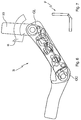
- FIG. 1 shows components of the inventively designed kinematics K of the vehicle seat, in a schematic exploded view.
- the kinematics K comprises a Lehnenschwenkgelenk GL for rotation of the backrest co-rotating with the backrest fitting 10 about an upper axis of rotation.
- the Lehnenschwenkgelenk GL is mechanically coupled to a pull arm 2 so that a rotational movement of the Lehenschwenkgelenks GL is transferable to the pull arm 2.
- the kinematics K further comprises a release member 3, which is in operative connection with the Lehnenschwenkgelenk GL via the Switzerlandarm 2..
- a lower pivot joint GU is non-rotatably connected to a fixed relative to the vehicle body lower fitting 40 to which an example in FIG. 3 represented seat part 4 is mounted.
- the kinematics K further comprises a lower locking unit VU for releasably locking the lower pivot joint GU.
- the locking unit VU in turn comprises a release arm 30, a locking cam 31 and a locking claw 32.
- a sliding strut 5 is provided with a guide slot which serves to guide the release arm 30.
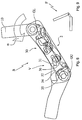
- FIG. 2 shows a schematic sectional view of the basic structure B of the vehicle seat F in a favorable for the vehicle occupant for driving position of use.
- the base structure B includes the backrest fitting 10, which is connected via the Lehnenschwenkgelenk GL hinged to an intermediate part 6.
- the intermediate part 6 is articulated via the lower pivot joint GU, about a lower axis of rotation rotatably on the lower fitting 40.
- the base structure B has an upper locking device for releasably locking the Lehnenschwenkgelenkes GL and a lower locking device V for releasably locking the lower pivot joint GU.
- the Lehnenschwenkgelenk GL is unlocked in this convenient for a vehicle occupant to drive use position of the base structure B, while the lower pivot joint GU is locked.
- the backrest can thus be changed for the comfort adjustment in its inclination angle ⁇ .
- a control slot 20 in the pulling arm 2 serves for the movable guidance of the release member and thereby ultimately allows the pivoting of the backrest fitting 10 within a certain pivoting range for the comfort adjustment of the backrest 1, without being acted upon in this comfort adjustment to the upper locking device or on the lower locking device V.
- the locking cam 31 abuts on a stop lug 33 of the locking claw 32 and thereby holds the locking claw 32 in a position in which a provided on the locking claw 32 first gear 34 with one with the lower Swivel joint GU operatively connected second toothing 35 cooperates, so as ultimately to lock the lower pivot joint GU.
- FIG. 3 shows in a highly schematic representation of a vehicle seat F in a seat-use position, the in FIG. 2 shown use position of the base structure B corresponds.
- the vehicle seat F has a seat part 4 and the backrest 1 connected to the seat part 4 via the intermediate part 6, which rotates together with the backrest fitting 10.
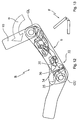
- FIG. 4 shows the basic structure B of FIG. 2 with respect to the FIG. 2 slightly, to the inclination angle ⁇ to the front folded backrest fitting 10.
- the backrest pivot joint GL is still unlocked, while the lower pivot joint GU is still locked.
- FIG. 5 shows in a highly schematic representation of the vehicle seat F in a sitting position, the in FIG. 4 shown position of the base structure B corresponds.
- FIG. 6 shows the basic structure B of Figure 4 with further (greater inclination angle ⁇ ) vorgeklapptem backrest fitting 10.
- the Lehnenschwenkgelenk GL is still unlocked, while the lower pivot joint GU is still locked.
- FIG. 7 shows in a highly schematic representation of the vehicle seat F in a sitting position, the in FIG. 6 shown position of the base structure B corresponds.
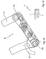
- FIG. 8 shows the basic structure B of FIG. 6 From this position of the backrest fitting 10 engages the standing with the Lehnenschwenkgelenk in operative connection pulling arm 2 on the release member, which in turn pushes a provided on release arm 30 pin in the guide slot of the slide strut.
- the release arm 30 begins to act on the lower locking device V such that the locking cam 31 dips into a blocking recess 36 provided on the locking claw 32, whereupon the locking claw 32 can move backwards, away from the lower pivot joint GU, and thus the first Gearing 34 begins to move away from the area of action of the second gearing 35 to thereby transfer the lower pivot joint GU from the locked state to the unlocked state.
- FIG. 9 shows the vehicle seat F in one of the in FIG. 8 shown position of the base structure B corresponding seating position, in a highly schematic representation.
- FIG. 10 shows the basic structure B of FIG. 8 with still further (again larger inclination angle ⁇ ) vorgeklapptem backrest fitting 10.
- the locking cam 31 is even deeper in the locking recess 36 penetrated, whereby the locking claw 32 could retreat further to the rear.
- FIG. 11 shows the vehicle seat F in one of the in FIG. 10 shown position of the basic structure B corresponding seat division, in a highly schematic representation.
- FIG. 12 shows the basic structure B of FIG. 10
- the locking cam 31 is now completely immersed in the locking recess 36, so that the locking claw 32 could retreat so far to the rear, that the first gear 34 and the second gear 35 now out of engagement with even further (even greater angle of inclination ⁇ ) vorgeklapptem backrest fitting with each other and thus the lower pivot joint GU is unlocked.
- the backrest pivot joint GL is still held in the unlocked state by a slider, the backrest fitting 10 is now in a ready-to-lock position ready for locking.
- the intermediate part 6 rotates with the backrest fitting 10 about the lower axis of rotation.
- FIG. 13 shows in a highly schematic representation of the vehicle seat F in a sitting position, the in FIG. 12 shown position of the base structure B corresponds.
- FIG. 14 shows the basic structure B of Figure 12
- the lower pivot joint GU initially remains in the unlocked state until it is transferred into a second locking position (change in the angle ⁇ ) when the backrest movement continues.
- the lower locking device V Before reaching this second locking position, however, on the one hand the lower locking device V is first brought into a ready-to-lock position as a result of the backrest movement and, on the other hand, the rotation of the intermediate part 6 about the lower rotational axis is limited by a second stop stop.
- the kinematics K is designed so that the backrest pivot joint GL and the lower pivot joint GU are locked automatically by their respective associated locking devices only after reaching the second stop stop.
- the coupled to the relative movement of the lower fitting 40 with respect to the intermediate part slider is moved back, after which the Lehnenschwenkgelenk GL begins to rotate into a locked position.
- the backrest fitting 10 is now in contact with a first stop stop, so that further movement of the backrest fitting 10 and thus the backrest 1 is blocked to the front.
- FIG. 15 shows in a highly schematic representation of the vehicle seat F in a sitting position, the in FIG. 14 shown position of the base structure B corresponds.
- FIG. 16 shows the basic structure B of Fig. 14 with even further (even greater inclination angle ⁇ ) vorgeklapptem backrest fitting 10. The slider was moved back further and the Lehnenschwenkgelenk GL continues to rotate to its locked position.
- FIG. 17 shows in a highly schematic representation of the vehicle seat F in one of in FIG. 16 shown position of the base structure B corresponding seat division.
- FIG. 18 shows the basic structure B of FIG. 16
- the backrest pivot joint GL and the lower pivot joint GU are now each latched in a locked position.
- FIG. 19 shows in a highly schematic representation of the vehicle seat F in a sitting position, the in FIG. 18 shown end position of the basic structure corresponds.
- the locked backrest 1 is now arranged approximately horizontally over the seat part 4.
- the front of the seat back 1 and the top of the seat part 4 face each other.
- FIG. 20 a preferred or an additional separate object of the present invention is shown, in which the backrest 1 is shortened when folding from the use position to the stowed position or vice versa, is extended.
- a power transmission means 8 here a toothed belt, driven, the force or torque directly or indirectly to a transmission 9, here a bevel gear. transmits, which drives the length adjustment of the backrest, 1.
Landscapes
- Engineering & Computer Science (AREA)
- Aviation & Aerospace Engineering (AREA)
- Transportation (AREA)
- Mechanical Engineering (AREA)
- Seats For Vehicles (AREA)
- Chairs For Special Purposes, Such As Reclining Chairs (AREA)
Description
Die Erfindung betrifft einen Kraftfahrzeugsitz, insbesondere einen Rücksitz für hintere Sitzreihen von Kraftfahrzeugen. Des weiteren betrifft die Erfindung ein Verfahren zur Verlagerung von einem ersten und einem zweiten Bauteilen relativ zu einem Basisteil, wobei das erste und das zweite Bauteil durch eine erstes Drehmittel und das zweite Bauteil und das Basisteil durch ein zweites Drehmittel jeweils miteinander verbunden sind.The invention relates to a motor vehicle seat, in particular a rear seat for rear seats of motor vehicles. Furthermore, the invention relates to a method for displacement of a first and a second components relative to a base part, wherein the first and the second component are connected to each other by a first rotating means and the second component and the base part by a second rotating means.
Kraftfahrzeugsitze, die zur Gewinnung von zusätzlichem Laderaum klappbar ausgeführt sind, sind in zahlreichen Ausgestaltungen am Markt vorhanden.Motor vehicle seats that are designed to be foldable to obtain additional cargo space are available in numerous configurations on the market.
Aus der
Der Erfindung liegt die Aufgabe zugrunde, ein Verfahren zum Umklappen einer Rückenlehne von der Gebrauchs- in die Verstaustellung und einen neuen, klappbaren Fahrzeugsitz vorzuschlagen, wobei der Fahrzeugsitz einfach aufgebaut und ohne wesentliche Vorkenntnisse des Nutzers zu bedienen ist und er im zusammengeklappten Zustand einen geringen Platzbedarf beansprucht.The invention has for its object to provide a method for folding a backrest of the use in the stowed position and a new, foldable vehicle seat, the vehicle seat is simple and without significant prior knowledge of the user to use and he in the folded state requires little space claimed.
Gelöst wird die Aufgabe mit einem Verfahren gemäß Anspruch 1.The problem is solved by a method according to
Das erfindungsgemäße Verfahren betrifft erfindungsgemäß die Verlagerung von einer Rückenlehne, dem ersten Bauteil, relativ zu einem Sitzteil, dem Basisteil, von einer Gebrauchsstellung, bei der die Rückenlehne im wesentlichen senkrecht zum Sitzteil vorgesehen ist, vorzugsweise über eine sogenannte, dem Fachmann geläufige Easy-Entry-Stellung, in eine Verstaustellung, in der die Rückenlehne im Wesentlichen parallel zu dem Sitzteil vorgesehen ist.According to the invention, the method according to the invention relates to the displacement of a backrest, the first component, relative to a seat part, the base part, from a use position in which the backrest is provided substantially perpendicular to the seat part, preferably via a so-called easy entry known to the person skilled in the art -Stellung, in a stowed position, in which the backrest is provided substantially parallel to the seat part.
Zwischen dem ersten Bauteil, nämlich der Rückenlehne, und dem Basisteil, nämlich dem Sitzteil, ist ein zweites Bauteil vorgesehen, das sowohl mit dem ersten Bauteil als auch mit dem Basisteil bewegbar, insbesondere drehbar, verbunden ist. Dafür sind erste und zweite Drehmittel, insbesondere Drehachsen vorgesehen, die vorzugsweise parallel zueinander angeordnet sind.Between the first component, namely the backrest, and the base part, namely the seat part, a second component is provided, which is movable, in particular rotatable, connected both to the first component and to the base part. Therefore are first and second rotating means, in particular rotation axes provided, which are preferably arranged parallel to each other.
Erfindungsgemäß ist nun vorgesehen, dass das erste und zweite Drehmittel in Abhängigkeit von mindestens einer Stellung des ersten Bauteils relativ zu dem zweiten Bauteil und/oder zweiten Bauteils relativ zu dem Basisteil automatisch ver- und entriegelt werden. Dadurch kann der Benutzer durch einfaches Drehen der Rückenlehne den Sitz von der Gebrauchsins die Verstaustellung überführen, ohne dass irgendwelche anderen Aktionen, wie beispielsweise Drücken von Knöpfen, Ziehen von Hebeln oder dergleichen vonnöten wäre.According to the invention, it is now provided that the first and second rotation means are automatically locked and unlocked relative to the base part relative to the second component and / or second component as a function of at least one position of the first component. Thus, by simply turning the backrest, the user can transfer the seat from the utility to the stowage position without the need for any other actions such as pushing buttons, pulling levers or the like.
Erfindungsgemäß kann das erste Bauteil, nämlich die Rückenlehne, relativ zu dem zweiten Bauteil verlagert, insbesondere um einen Winkel gedreht werden, wobei das zweite Bauteil relativ zu dem Basisteil, beispielsweise dem Sitzteil, in einer ersten Position verriegelt bleibt. Diese Funktion ist insbesondere zur Komfortverstellung wichtig. Der Anstellwinkel der Rückenlehne kann um seine senkrechte Stellung herum verstellt werden, ohne dass die Verriegelung zwischen dem zweiten Bauteil und dem Sitzteil gelöst wird.According to the invention, the first component, namely the backrest, can be displaced relative to the second component, in particular rotated through an angle, the second component remaining locked relative to the base part, for example the seat part, in a first position. This function is particularly important for comfort adjustment. The angle of attack of the backrest can be adjusted around its vertical position without the lock between the second component and the seat part is released.
Bei einer Drehung des ersten Bauteils, nämlich die Rückenlehne, über einen bestimmten Winkel hinaus, wird das zweite Drehmittel automatisch entriegelt und/oder das erste Bauteil mit einem an dem zweiten Bauteil vorgesehenen Anschlag zur Anlage gebracht wird. Diese Funktion ermöglicht es die Rückenlehne in eine Easy-Entry-Stellung zu überführen.Upon rotation of the first component, namely the backrest, beyond a certain angle, the second rotating means is automatically unlocked and / or the first component is brought into abutment with a stop provided on the second component. This function allows the backrest to be transferred to an easy-entry position.
Vorzugsweis wird bei einer, insbesondere weiteren, Relativbewegung zwischen dem zweiten Bauteil und dem Basisteil, ein Verriegelungsmittel des ersten Bauteils automatisch in eine verriegelbare Position gebracht, d.h. das Verriegelungsmittel könnte das erste Bauteil relativ zu dem zweiten Bauteil verriegeln, hat aber noch nicht verriegelt.Preferably, in a, in particular further, relative movement between the second component and the base part, a locking means of the first component is automatically brought into a lockable position, i. the locking means could lock the first component relative to the second component, but has not yet locked.
Vorzugsweise wird ein Verriegelungsmittel des zweiten Bauteils relativ zu dem Basisteil ebenfalls, vorzugsweise gleichzeitig mit dem Verriegelungsmittel des ersten Bauteils, automatisch in eine verriegelbare, zweite Position gebracht wird, d.h. auch dieses Verriegelungsmittel könnte das zweite Bauteil relativ zu dem Basisteil verriegeln, hat aber noch nicht verriegelt.Preferably, a locking means of the second component relative to the base part is also automatically brought into a lockable, second position, preferably simultaneously with the locking means of the first component, i. also this locking means could lock the second component relative to the base part, but has not yet locked.
Vorzugsweise werden beide Baufeile automatisch in ihrer jeweiligen Position verriegelt, nachdem das Bauteil seine Endposition erreicht hat. Diese Stellung ist dann beispielsweise die Verstaustellung der Rückenlehne parallel zu dem Sitzteil.Preferably, both parts are automatically locked in their respective position after the component has reached its end position. This position is then, for example, the stowage of the backrest parallel to the seat part.
Vorzugsweise erfolgt die Verriegelung durch ein Rastmittel, insbesondere eine Rastklinke.Preferably, the locking is effected by a latching means, in particular a latching pawl.
Vorzugsweise muss das zweite Bauteil, insbesondere nachdem es in seine zweite Position, beispielsweise die Verstauposition der Rückenlehne verbracht worden ist, manuell oder motorisch entriegelt werden.Preferably, the second component, in particular after it has been moved to its second position, for example, the stowed position of the backrest, must be unlocked manually or by motor.
Vorzugsweise erfolgt dann bei der Bewegung des Bauteils und des Basisteils relativ zueinander, die Entriegelung des ersten Bauteils automatisch.Preferably then takes place during the movement of the component and the base part relative to each other, the unlocking of the first component automatically.
In einer bevorzugten Ausführungsform der vorliegenden Erfindung wird bei einer Bewegung des ersten Bauteils und des zweiten Bauteils relativ zueinander und/oder bei einer Bewegung des zweiten Bauteils relativ zu dem Basisteil das erste Bauteil automatisch verkürzt oder verlängert.In a preferred embodiment of the present invention, the first component is automatically shortened or extended during a movement of the first component and the second component relative to one another and / or during a movement of the second component relative to the base part.
Vorzugsweise ist das erste Bauteil die Rückenlehne und/oder das Basisteil der Sitzteil eines Fahrzeugsitzes.Preferably, the first component is the backrest and / or the base part of the seat part of a vehicle seat.
Ein weiterer Gegenstand ist ein Fahrzeugsitz gemäß Anspruch 11. Besonders bevorzugt bewegt sich dieses Mittel rein translatorisch. Die zu dem erfindungsgemäßen Verfahren gemachten Ausführungen gelten für den erfindungsgemäßen Fahrzeugsitz gleichermaßen und umgekehrt.Another object is a vehicle seat according to
Vorzugsweise weist der Fahrzeugsitz einen, um eine obere horizontale Drehachse schwenkbaren, oberen Beschlag auf, mit dem in der Regel die Rückenlehne verbunden ist und der über einen oberen Verriegelungsmechanismus lösbar vorriegelbar ist. Der Fahrzeugsitz weist ferner ein zweites Bauteil, ein Zwischenteil, auf, das vorzugsweise um eine untere horizontale Achse schwenkbar an einem unteren Beschlag angelenkt ist und vorzugsweise über einen unteren Verriegelungsmechanismus lösbar verriegelbar ist. Der unter Beschlag ist in der Regel mit einem Sitzteil verbunden.The vehicle seat preferably has an upper fitting, which is pivotable about an upper horizontal axis of rotation, to which the backrest is generally connected and which can be releasably locked by means of an upper locking mechanism. The vehicle seat further comprises a second component, an intermediate part, which is preferably pivotally connected about a lower horizontal axis to a lower fitting and is preferably releasably lockable via a lower locking mechanism. The under fitting is usually connected to a seat part.
Die Kinematik dieses Fahrzeugsitzes ist vorzugsweise derart ausgeführt, dass
- die obere Drehachse entriegelt und die untere Drehachse verriegelt ist, wenn sich die Rückenlehne in einer Gebrauchsstellung, d.h. in einer für den Fahrzeuginsassen zum Fahren günstigen Lage befindet;
- die untere Drehachse selbsttätig entriegelt wird, sobald die Rückenlehne beim Vorklappen einen vorbestimmten Neigungswinkel gegenüber der Senkrechten erreicht;
- die Vorklappbewegung der Rückenlehne durch erste Stopmittel, insbesondere in der dem vorbestimmten Neigungswinkel entsprechenden Stopstellung der Rückenlehne begrenzt wird;
- nach der Entriegelung der unteren Drehachse, bei fortgesetzter Bewegung des oberen Beschlages, die Bewegung des oberen Beschlages auf das Zwischenteil übertragen, die Bewegung des Zwischenteil durch ein zweites Stopmittel begrenzt, und dadurch das Zwischenteil in einer definierten funktionalen Stellung gestoppt wird und/oder
- die obere und die untere Drehachse jeweils erst dann verriegelt werden, wenn der erfindungsgemäße Fahrzeugsitz in eine Endposition verstellt ist, in der die Rückenlehne in einer flachen Stellung über dem Sitzteil angeordnet ist; - die obere und die untere Drehachse in der Endposition des Sitzes nur durch eine irgendwie geartete, auf die Kinematik einwirkende, gezielte Betätigung seitens eines Nutzers entriegelt werden kann.
- unlocks the upper axis of rotation and the lower axis of rotation is locked when the backrest is in a position of use, ie in a position favorable for the vehicle occupant to drive;
- the lower axis of rotation is automatically unlocked as soon as the backrest reaches a predetermined angle of inclination with respect to the vertical when folding;
- the Vorklappbewegung the backrest is limited by first stop means, in particular in the predetermined inclination angle corresponding stop position of the backrest;
- after unlocking the lower axis of rotation, with continued movement of the upper fitting, transmit the movement of the upper fitting to the intermediate part, limits the movement of the intermediate part by a second stop means, and thereby the intermediate part is stopped in a defined functional position and / or
- the upper and lower axes of rotation are respectively locked only when the vehicle seat according to the invention is adjusted to an end position in which the backrest is arranged in a flat position above the seat part; - The upper and lower pivot axis in the end position of the seat can only be unlocked by any kind, acting on the kinematics, targeted operation by a user.
Im Folgenden werden die Erfindungen anhand der
Es zeigen:
-
Figur 1 - Komponenten der erfindungsgemäß ausgeführten Kinematik des Fahrzeugsitzes, in schematischer Explosionsdarstellung;
-
Figur 2 - eine Basisstruktur des Fahrzeugsitzes in einer ersten Stellung, der Gebrauchsstellung, in schematischer Schnittdarstellung;
-
Figur 3 - einen Fahrzeugsitz in einer der in
Figur 2 -
Figur 4 - die Basisstruktur von
Figur 2Figur 2 -
Figur 5 - den Fahrzeugsitz in einer der in
Figur 4 -
Figur 6 - die Basisstruktur von
Figur 4 -
Figur 7 - der Fahrzeugsitz in einer der in
Figur 6 -
Figur 8 - die Basisstruktur von
Figur 6 -
Figur 9 - den Fahrzeugsitz in einer der in
Figur 8 -
Figur 10 - die
Basisstruktur von Figur 8 mit noch weiter vorgeklapptem Lehnenbeschlag; -
Figur 11 - den Fahrzeugsitz in einer der in
Figur 10 - Figur 12
- die Basisstruktur von
Fig.10 mit noch weiter vorgeklapptem Lehnenbeschlag; - Figur 13
- den Fahrzeugsitz in einer der in
Figur 12 gezeigten Stellung der Basisstruktur entsprechenden Sitzstellung, in stark schematisierter Darstellung; - Figur 14
- die Basisstruktur von
Fig. 12 mit noch weiter vorgeklapptem Lehnenbeschlag; - Figur 15
- den Fahrzeugsitz in einer der in Figur' 14, gezeigten Stellung der Basisstruktur entsprechenden Sitzstellung, in stark schematisierter Darstellung;
- Figur 16
- die Basisstruktur von
Fig. 14 mit noch weiter vorgeklapptem Lehnenbeschlag; - Figur 17
- den Fahrzeugsitz in einer der in
Figur 16 gezeigten Stellung der Basisstruktur entsprechenden Sitzstellung, in stark schematisierter Darstellung; - Figur 18
- die Basisstruktur von
Fig.16 mit in die waagerechte Endstellung weiter vorgeklapptem Lehnenbeschlag; - Figur 19
- den Fahrzeugsitz in einer der in
Figur 18 gezeigten Endstellung der Basisstruktur entsprechenden Sitzendstellung, in stark schematisierter Darstellung; -
Figur 20 - zeigt die Verlängerung und Verkürzung der Rückenlehne;
- FIG. 1
- Components of the inventively designed kinematics of the vehicle seat, in a schematic exploded view;
- FIG. 2
- a basic structure of the vehicle seat in a first position, the position of use, in a schematic sectional view;
- FIG. 3
- a vehicle seat in one of the in
FIG. 2 shown use position of the base structure corresponding SitzUebsstellung, in a highly schematic representation; - FIG. 4
- the basic structure of
FIG. 2 with respect to theFIG. 2 slightly reclined backrest fitting; - FIG. 5
- the vehicle seat in one of the in
FIG. 4 shown position of the base structure corresponding seating position, in a highly schematic representation; - FIG. 6
- the basic structure of
FIG. 4 with backrest fitting folded forward into the upright position; - FIG. 7
- the vehicle seat in one of the in
FIG. 6 shown position-the base structure corresponding seating position, in a highly schematic representation; - FIG. 8
- the basic structure of
FIG. 6 with even further folded backrest fitting; - FIG. 9
- the vehicle seat in one of the in
FIG. 8 shown position of the base structure corresponding seating position, in a highly schematic representation; - FIG. 10
- the basic structure of
FIG. 8 with even further folded backrest fitting; - FIG. 11
- the vehicle seat in one of the in
FIG. 10 shown position of the base structure corresponding seating position, in a highly schematic representation; - FIG. 12
- the basic structure of
Figure 10 with even further folded backrest fitting; - FIG. 13
- the vehicle seat in one of the in
FIG. 12 shown position of the base structure corresponding seating position, in a highly schematic representation; - FIG. 14
- the basic structure of
Fig. 12 with even further folded backrest fitting; - FIG. 15
- the vehicle seat in a sitting position corresponding to the position of the base structure shown in FIG. 14, in a highly schematic representation;
- FIG. 16
- the basic structure of
Fig. 14 with even further folded backrest fitting; - FIG. 17
- the vehicle seat in one of the in
FIG. 16 shown position of the base structure corresponding seating position, in a highly schematic representation; - FIG. 18
- the basic structure of
Figure 16 with in the horizontal end position weiterklapptem backrest fitting; - FIG. 19
- the vehicle seat in one of the in
FIG. 18 shown end position of the base structure corresponding Sitzendstellung, in a highly schematic representation; - FIG. 20
- shows the extension and shortening of the backrest;
Das Lehnenschwenkgelenk GL ist mit einem Zugarm 2 mechanisch so gekoppelt, dass eine Drehbewegung des Lehnenschwenkgelenks GL auf den Zugarm 2 übertragbar ist.The Lehnenschwenkgelenk GL is mechanically coupled to a
Die Kinematik K umfasst ferner ein Löseorgan 3, das über den Zugarm 2.mit dem Lehnenschwenkgelenk GL in Wirkverbindung steht.The kinematics K further comprises a
Ein unteres Schwenkgelenk GU ist drehfest mit einem bezüglich der Fahrzeugkarosserie feststehenden unteren Beschlag 40 verbunden, an dem ein z.B. in
Die Kinematik K weist ferner eine untere Verriegelungseinheit VU zur lösbaren Verriegelung des unteren Schwenkgelenks GU auf. Die Verriegelungseinheit VU umfasst ihrerseits einen Lösearm 30, einen Sperrnocken 31 und eine Sperrklaue 32. Mit einer oberen Verriegelungseinheit VL kann der Beschlag 10 und damit die Rückenlehne relativ zu dem ZwischenteilThe kinematics K further comprises a lower locking unit VU for releasably locking the lower pivot joint GU. The locking unit VU in turn comprises a
Eine Gleitstrebe 5 ist mit einem Führungsschlitz versehen, der der Führung des Lösearms 30 dient.A sliding
Die Basisstruktur B weist eine obere Verriegelungseinrichtung zur lösbaren Verriegelung des Lehnenschwenkgelenkes GL und eine untere Verriegelungseinrichtung V zur lösbaren Verriegelung des unteren Schwenkgelenks GU auf.The base structure B has an upper locking device for releasably locking the Lehnenschwenkgelenkes GL and a lower locking device V for releasably locking the lower pivot joint GU.
Das Lehnenschwenkgelenk GL ist in dieser für einen Fahrzeuginsassen zum Fahren günstigen Gebrauchsstellung der Basisstruktur B entriegelt, während das untere Schwenkgelenk GU verriegelt ist. Die Rückenlehne kann folglich für die Komfortverstellung in ihrem Neigungswinkel α verändert werden.The Lehnenschwenkgelenk GL is unlocked in this convenient for a vehicle occupant to drive use position of the base structure B, while the lower pivot joint GU is locked. The backrest can thus be changed for the comfort adjustment in its inclination angle α.
Ein Steuerschlitz 20 im Zugarm 2 dient der beweglichen Führung des Löseorgans und erlaubt dadurch letztlich das Verschwenken des Lehnenbeschlags 10 innerhalb eines bestimmten Schwenkbereiches für die Komfortverstellung der Rückenlehne 1, ohne dass bei dieser Komfortverstellung auf die obere Verriegelungseinrichtung oder auf die untere Verriegelungseinrichtung V eingewirkt wird. Der Sperrnocken 31 liegt an einer Anschlagnase 33 der Sperrklaue 32 an und hält die Sperrklaue 32 dadurch in einer Position, in der eine an der Sperrklaue 32 vorgesehen erste Verzahnung 34 mit einer mit dem unteren Schwenkgelenk GU wirkverbundenen zweiten Verzahnung 35 zusammenwirkt, um so letztlich das untere Schwenkgelenk GU zu verriegeln.A
Um die Verriegelung des Lehnenschwenkgelenks GL und des unteren Schwenkgelenks GU in dieser Endstellung des Fahrzeugsitzes F zu lösen, ist es erforderlich, dass der Nutzer beispielsweise manuell oder über irgendwelche Aktuatoren die Verriegelung des unteren Schwenkgelenkes GU löst, wonach der Sitz wieder in die Ausgangsstellung d.h. in die Gebrauchsstellung verstellt werden kann. Das obere Schwenkgelenk GL entriegelt sich bei der Rückwärtsbewegung der Rückenlehne selbsttätig.In order to release the locking of the Lehnenschwenkgelenks GL and the lower pivot joint GU in this end position of the vehicle seat F, it is necessary that the user solves, for example manually or via any actuators, the locking of the lower pivot joint GU, after which the seat back to the starting position. can be adjusted in the use position. The upper pivot joint GL unlocks automatically during the backward movement of the backrest.
In
Bei dem erläuterten Ausführungsbeispiel gemäß den
- 11
- erstes Bauteil, Rückenlehnefirst component, backrest
- 22
- Zugarmpulling arm
- 33
- Löseorgandetaching means
- 44
- Basisteil, SitzteilBase part, seat part
- 55
- GleitstrebeGleitstrebe
- 66
- zweites Bauteil, Zwischenteilsecond component, intermediate part
- 77
- Rastmittel, SperrnockenLocking means, locking cams
- 88th
- Kraftübertragungsmittel, ZahnriemenPower transmission means, toothed belt
- 99
- Getriebetransmission
- 1010
- Lehnenbeschlagbackrest fitment
- 1111
- Gelenkjoint
- 3030
- Lösearmrelease arm
- 3131
- Rastmittel, SperrnockenLocking means, locking cams
- 3232
- Sperrklauelocking pawl
- 3333
- Anschlagnasestop lug
- 3434
- Verzahnunggearing
- 3535
- Verzahnunggearing
- 3636
- Sperrvertiefungblocking recess
- 4040
- Beschlagfitting
- BB
- Basisstrukturbase structure
- FF
- Fahrzeugsitzvehicle seat
- GLGL
- erstes Drehmittel, Lehnenschwenkgelenkfirst turning means, backrest swivel joint
- GUGU
- zweites Drehmittel, Schwenkgelenksecond turning means, pivoting joint
- VLVL
- Verriegelungseinrichtung des ersten DrehmittelsLocking device of the first rotating means
- VUVU
- Verriegelungseinrichtung des zweiten DrehmittelsLocking device of the second rotating means
- αα
- Winkel zwischen dem ersten und dem zweiten BauteilAngle between the first and the second component
- ββ
- Winkel zwischen dem zweiten Bauteil und dem BasisteilAngle between the second component and the base part
Claims (12)
- Method for shifting a first and a second component (1, 6) relative to a base part (4) from a use position via an easy entry position to a stowed position, wherein a seatback (1) is provided as the first component (1) and a seat part (4) of a vehicle seat is provided as the base part (4), wherein the first and the second component (1, 6) are in each case connected to each other by a first rotational means (GL) and the second component (6) and the base part (4) are in each case connected to each other by a second rotational means (GU), wherein the first and second rotational means (GL, GU) are automatically locked and unlocked depending on at least one position of the first component (1) relative to the second component (6) and/or of the second component (6) relative to the base part (4), characterized in that the first rotational means (GL) is not locked when the seatback (1) is in the use position, and in that, by way of a mechanical coupling of the first rotational means (GL) to a pull arm (2), the rotational movement of the first rotational means (GL) is transmitted to the pull arm (2), which provides an operative connection between a release member (3) and the first rotational means (GL), wherein a control slot (20) of the pull arm (2) serves for the movable guidance of the release member (3) and thus permits ultimately the pivoting of a joint fitting (10), which rotates together with the seatback, within a specific pivoting range for a comfort adjustment of the seatback (1).
- Method according to Claim 1, characterized in that in a first position the seatback (1) is shifted, in particular by an angle (α), relative to the second component and the second component remains locked in a first position relative to the seat part.
- Method according to Claim 1 or 2, characterized in that when rotating the seatback (1) beyond a specific angle (α), the second rotational means (GU) is automatically unlocked and/or the seatback (1) is brought into contact with a stop provided on the second component (6).
- Method according to Claim 3, characterized in that with a relative movement between the second component (6) and the seat part (4), a locking means (VL) of the seatback (1) is automatically brought into a lockable position.
- Method according to Claim 4, characterized in that a locking means (VU) of the second component (6) is also automatically brought into a lockable second position, preferably at the same time as the locking means of the seatback (1).
- Method according to Claim 5, characterized in that both components (1, 6) are automatically locked in their respective positions after the seatback (1) has reached its end position.
- Method according to one of the preceding claims, characterized in that the locking takes place by a latching means, in particular a latching pawl.
- Method according to Claim 6 or 7, characterized in that the second component (6) is unlocked in a manual or motorized manner.
- Method according to Claim 8, characterized in that the locking of the seatback (1) takes place automatically with a movement of the second component (6) and the seat part (4) relative to one another.
- Method according to one of the preceding claims, characterized in that with a movement of the seatback (1) and the second component (6) relative to one another, and/or with a movement of the second component (6) relative to the seat part (4), the seatback (1) is automatically shortened or lengthened.
- Vehicle seat comprising a seatback (1), an intermediate part (6) and a seat part (4) as a base part (4), wherein the vehicle seat can be adjusted from a use position via an easy position to a stowed position, wherein the seatback (1) and the intermediate part (6) are in each case connected to each other by a first rotational means (GL) and the intermediate part (6) and the seat part (4) are in each case connected to each other by a second rotational means (GU), which in each case are able to be locked in at least one position by a locking means (VL, VU), wherein the locking means (VL, VU) are operatively connected by a means (5) so that with a relative movement (α, β) between the seatback (1) and the intermediate part (6), and/or the intermediate part (6) and the base part (4), at least one locking means (VL, VU) is automatically locked and unlocked, characterized in that the first rotational means (GL) is not locked by the locking means (VL) when the seatback (1) is in the use position, and in that the first rotational means (GL) is mechanically coupled to a pull arm (2) such that the rotational movement of the first rotational means (GL) is transmitted to the pull arm, which provides an operative connection between a release member (3) and the first rotational means (GL), wherein a control slot (20) of the pull arm (2) serves for the movable guidance of the release member (3) and thus permits ultimately the pivoting of a joint fitting (10), which rotates together with the seatback, within a specific pivoting range for a comfort adjustment of the seatback (1).
- Vehicle seat according to Claim 11, characterized in that the means (5) are moved in a purely translatory manner.
Applications Claiming Priority (3)
| Application Number | Priority Date | Filing Date | Title |
|---|---|---|---|
| DE102009036138 | 2009-08-05 | ||
| DE102010023765.5A DE102010023765B4 (en) | 2009-08-05 | 2010-06-15 | Method for transferring a backrest from the utility to a stowage position and motor vehicle seat |
| PCT/EP2010/004667 WO2011015315A1 (en) | 2009-08-05 | 2010-07-30 | Motor vehicle seat and method for transferring a seatback from the use position to a stowed position |
Publications (2)
| Publication Number | Publication Date |
|---|---|
| EP2462002A1 EP2462002A1 (en) | 2012-06-13 |
| EP2462002B1 true EP2462002B1 (en) | 2016-09-28 |
Family
ID=43448412
Family Applications (1)
| Application Number | Title | Priority Date | Filing Date |
|---|---|---|---|
| EP10744871.4A Not-in-force EP2462002B1 (en) | 2009-08-05 | 2010-07-30 | Motor vehicle seat and method for transferring a seatback from the use position to a stowed position |
Country Status (8)
| Country | Link |
|---|---|
| US (1) | US8974001B2 (en) |
| EP (1) | EP2462002B1 (en) |
| JP (1) | JP5674784B2 (en) |
| KR (1) | KR101345678B1 (en) |
| CN (1) | CN102548793B (en) |
| DE (1) | DE102010023765B4 (en) |
| IN (1) | IN2012DN00993A (en) |
| WO (1) | WO2011015315A1 (en) |
Families Citing this family (9)
| Publication number | Priority date | Publication date | Assignee | Title |
|---|---|---|---|---|
| DE102012012983B4 (en) * | 2012-06-29 | 2014-04-24 | Isringhausen Gmbh & Co. Kg | Vehicle seat with backrest tilt adjustment and shoulder adjustment |
| US9085252B2 (en) * | 2013-05-02 | 2015-07-21 | GM Global Technology Operations LLC | Vehicle seat assembly with dual locked seating positions and method of adjusting a vehicle seat |
| US10166888B2 (en) * | 2013-09-18 | 2019-01-01 | Ts Tech Co., Ltd. | Vehicle seat |
| US9622593B2 (en) * | 2014-01-14 | 2017-04-18 | Artsana Usa, Inc. | Pinch free folding lock |
| US10149552B2 (en) | 2015-01-06 | 2018-12-11 | Artsana Usa, Inc. | Pinch free folding lock |
| JP6871506B2 (en) | 2017-02-08 | 2021-05-12 | テイ・エス テック株式会社 | Vehicle seats with center-folded seatbacks and center-folded seatbacks |
| CN110920738B (en) * | 2018-09-19 | 2022-07-26 | 明门瑞士股份有限公司 | Rotary safety mechanism and seat with same |
| US11833937B2 (en) * | 2021-09-08 | 2023-12-05 | Faurecia Automotive Seating, Llc | Occupant support |
| CN114290967B (en) * | 2022-01-10 | 2023-07-04 | 浙江吉利控股集团有限公司 | Seat skeleton, seat and vehicle |
Citations (1)
| Publication number | Priority date | Publication date | Assignee | Title |
|---|---|---|---|---|
| US1663898A (en) * | 1924-09-18 | 1928-03-27 | Frank C Bitzenburger | Yieldable back support for seats |
Family Cites Families (11)
| Publication number | Priority date | Publication date | Assignee | Title |
|---|---|---|---|---|
| EP0410814B1 (en) | 1989-07-28 | 1995-09-13 | Fuji Kiko Company Limited | Automotive seat with walk-in mechanism |
| CN2093112U (en) * | 1991-03-23 | 1992-01-15 | 施克礼 | Double-hinge seat adjustable angle device for car |
| KR100291936B1 (en) * | 1997-08-30 | 2001-11-26 | 이계안 | Device for interlocking reclining and turning of seat for vehicle |
| FR2799420B1 (en) * | 1999-10-08 | 2002-01-04 | Faure Bertrand Equipements Sa | VEHICLE SEAT |
| US6513876B1 (en) * | 2000-11-17 | 2003-02-04 | Gayle D. Agler | Multiple function boat seat |
| CA2390667C (en) * | 2001-06-15 | 2006-01-03 | Faurecia Automotive Seating Canada Limited | Improved vehicle seat hinge mechanism with reclining with forward dumping, memory return and fold-flat functionality |
| DE10132701B4 (en) * | 2001-07-05 | 2008-11-06 | Keiper Gmbh & Co.Kg | Fitting for a vehicle seat |
| DE10149858C2 (en) * | 2001-10-10 | 2003-10-02 | Johnson Controls Gmbh | Vehicle seat with swiveling backrest |
| KR100461102B1 (en) * | 2002-08-08 | 2004-12-13 | 현대자동차주식회사 | A reclining device for a rear seat in automobile |
| FR2899161B1 (en) * | 2006-03-30 | 2009-03-20 | Renault Sas | REPLIABLE AUTOMOTIVE VEHICLE SEAT |
| CN101883697B (en) * | 2007-12-03 | 2012-08-15 | 丰田纺织株式会社 | Vehicle seat |
-
2010
- 2010-06-15 DE DE102010023765.5A patent/DE102010023765B4/en not_active Expired - Fee Related
- 2010-07-30 US US13/387,132 patent/US8974001B2/en active Active
- 2010-07-30 IN IN993DEN2012 patent/IN2012DN00993A/en unknown
- 2010-07-30 WO PCT/EP2010/004667 patent/WO2011015315A1/en not_active Ceased
- 2010-07-30 EP EP10744871.4A patent/EP2462002B1/en not_active Not-in-force
- 2010-07-30 KR KR1020127005873A patent/KR101345678B1/en not_active Expired - Fee Related
- 2010-07-30 JP JP2012523231A patent/JP5674784B2/en not_active Expired - Fee Related
- 2010-07-30 CN CN201080042798.6A patent/CN102548793B/en not_active Expired - Fee Related
Patent Citations (1)
| Publication number | Priority date | Publication date | Assignee | Title |
|---|---|---|---|---|
| US1663898A (en) * | 1924-09-18 | 1928-03-27 | Frank C Bitzenburger | Yieldable back support for seats |
Also Published As
| Publication number | Publication date |
|---|---|
| CN102548793A (en) | 2012-07-04 |
| US8974001B2 (en) | 2015-03-10 |
| JP5674784B2 (en) | 2015-02-25 |
| DE102010023765B4 (en) | 2018-04-26 |
| IN2012DN00993A (en) | 2015-04-10 |
| JP2013500896A (en) | 2013-01-10 |
| EP2462002A1 (en) | 2012-06-13 |
| US20120139317A1 (en) | 2012-06-07 |
| DE102010023765A1 (en) | 2011-02-17 |
| WO2011015315A1 (en) | 2011-02-10 |
| KR20120049328A (en) | 2012-05-16 |
| KR101345678B1 (en) | 2013-12-30 |
| CN102548793B (en) | 2015-05-20 |
Similar Documents
| Publication | Publication Date | Title |
|---|---|---|
| EP2462002B1 (en) | Motor vehicle seat and method for transferring a seatback from the use position to a stowed position | |
| DE69806472T2 (en) | One-hand relief lever for a vehicle seat | |
| DE69500344T2 (en) | Articulated fitting for a vehicle seat back | |
| EP2734409B1 (en) | Seat fitting for a motor vehicle seat | |
| DE102015200816B4 (en) | Propulsion system for tilt adjustment, vehicle seat, method of operating a propulsion system | |
| WO2019048399A1 (en) | REVERSIBLE VEHICLE SEAT | |
| DE19758237A1 (en) | Car seat for two door vehicles | |
| DE102015204273A1 (en) | Vehicle seat with easy-entry function | |
| EP3670251A1 (en) | Passenger protection system comprising an activatable backrest part of a vehicle seat | |
| WO2008116436A1 (en) | Vehicle seat | |
| WO2010029010A2 (en) | Seat arrangement for a vehicle and method for adjusting a seat part | |
| WO2021214127A1 (en) | Vehicle seat with a kinematic lever | |
| DE102013000164B4 (en) | Vehicle seat, in particular for a passenger car | |
| DE102017010409B4 (en) | Towbar for a vehicle | |
| DE102005003817B4 (en) | Motor vehicle seat with folding backrest | |
| DE10142830B4 (en) | Drive for at least one manually operated adjustment device on a vehicle seat | |
| WO2019201973A1 (en) | Vehicle seat, in particular motor vehicle seat | |
| DE102018213141B3 (en) | Adjustment device for at least partially lowering a seat part with drive device | |
| DE102007017673B4 (en) | vehicle seat | |
| DE10246473A1 (en) | Seat arrangement for motor vehicle seat has backrest adjustable by means of lever device relative to seat mounting frame | |
| DE102010045738B4 (en) | Vehicle seat with a memory device | |
| EP1968815B1 (en) | Motor vehicle seat featuring coupling between the backrest movement and the seat part movement, and motor vehicle comprising such a motor vehicle seat | |
| DE102004024173B4 (en) | Fitting system for a vehicle seat | |
| DE10064794A1 (en) | Car seat has back rest made up of two sections, inclination of lower section being adjustable and the upper section pivoting, and two sections being held together by fixed lever on upper section and pivoting lever on lower section | |
| DE20215321U1 (en) | Seat arrangement for motor vehicle seat has backrest adjustable by means of lever device relative to seat mounting frame |
Legal Events
| Date | Code | Title | Description |
|---|---|---|---|
| PUAI | Public reference made under article 153(3) epc to a published international application that has entered the european phase |
Free format text: ORIGINAL CODE: 0009012 |
|
| 17P | Request for examination filed |
Effective date: 20120305 |
|
| AK | Designated contracting states |
Kind code of ref document: A1 Designated state(s): AL AT BE BG CH CY CZ DE DK EE ES FI FR GB GR HR HU IE IS IT LI LT LU LV MC MK MT NL NO PL PT RO SE SI SK SM TR |
|
| RIN1 | Information on inventor provided before grant (corrected) |
Inventor name: EWALD, TOBIAS Inventor name: FAHL, MICHAEL |
|
| DAX | Request for extension of the european patent (deleted) | ||
| 17Q | First examination report despatched |
Effective date: 20150302 |
|
| GRAP | Despatch of communication of intention to grant a patent |
Free format text: ORIGINAL CODE: EPIDOSNIGR1 |
|
| INTG | Intention to grant announced |
Effective date: 20160418 |
|
| GRAS | Grant fee paid |
Free format text: ORIGINAL CODE: EPIDOSNIGR3 |
|
| GRAA | (expected) grant |
Free format text: ORIGINAL CODE: 0009210 |
|
| AK | Designated contracting states |
Kind code of ref document: B1 Designated state(s): AL AT BE BG CH CY CZ DE DK EE ES FI FR GB GR HR HU IE IS IT LI LT LU LV MC MK MT NL NO PL PT RO SE SI SK SM TR |
|
| REG | Reference to a national code |
Ref country code: GB Ref legal event code: FG4D Free format text: NOT ENGLISH |
|
| REG | Reference to a national code |
Ref country code: CH Ref legal event code: EP |
|
| REG | Reference to a national code |
Ref country code: AT Ref legal event code: REF Ref document number: 832429 Country of ref document: AT Kind code of ref document: T Effective date: 20161015 |
|
| REG | Reference to a national code |
Ref country code: IE Ref legal event code: FG4D Free format text: LANGUAGE OF EP DOCUMENT: GERMAN |
|
| REG | Reference to a national code |
Ref country code: DE Ref legal event code: R096 Ref document number: 502010012478 Country of ref document: DE |
|
| REG | Reference to a national code |
Ref country code: LT Ref legal event code: MG4D |
|
| PG25 | Lapsed in a contracting state [announced via postgrant information from national office to epo] |
Ref country code: HR Free format text: LAPSE BECAUSE OF FAILURE TO SUBMIT A TRANSLATION OF THE DESCRIPTION OR TO PAY THE FEE WITHIN THE PRESCRIBED TIME-LIMIT Effective date: 20160928 Ref country code: FI Free format text: LAPSE BECAUSE OF FAILURE TO SUBMIT A TRANSLATION OF THE DESCRIPTION OR TO PAY THE FEE WITHIN THE PRESCRIBED TIME-LIMIT Effective date: 20160928 Ref country code: NO Free format text: LAPSE BECAUSE OF FAILURE TO SUBMIT A TRANSLATION OF THE DESCRIPTION OR TO PAY THE FEE WITHIN THE PRESCRIBED TIME-LIMIT Effective date: 20161228 Ref country code: LT Free format text: LAPSE BECAUSE OF FAILURE TO SUBMIT A TRANSLATION OF THE DESCRIPTION OR TO PAY THE FEE WITHIN THE PRESCRIBED TIME-LIMIT Effective date: 20160928 |
|
| REG | Reference to a national code |
Ref country code: NL Ref legal event code: MP Effective date: 20160928 |
|
| PG25 | Lapsed in a contracting state [announced via postgrant information from national office to epo] |
Ref country code: NL Free format text: LAPSE BECAUSE OF FAILURE TO SUBMIT A TRANSLATION OF THE DESCRIPTION OR TO PAY THE FEE WITHIN THE PRESCRIBED TIME-LIMIT Effective date: 20160928 Ref country code: GR Free format text: LAPSE BECAUSE OF FAILURE TO SUBMIT A TRANSLATION OF THE DESCRIPTION OR TO PAY THE FEE WITHIN THE PRESCRIBED TIME-LIMIT Effective date: 20161229 Ref country code: LV Free format text: LAPSE BECAUSE OF FAILURE TO SUBMIT A TRANSLATION OF THE DESCRIPTION OR TO PAY THE FEE WITHIN THE PRESCRIBED TIME-LIMIT Effective date: 20160928 Ref country code: SE Free format text: LAPSE BECAUSE OF FAILURE TO SUBMIT A TRANSLATION OF THE DESCRIPTION OR TO PAY THE FEE WITHIN THE PRESCRIBED TIME-LIMIT Effective date: 20160928 |
|
| PG25 | Lapsed in a contracting state [announced via postgrant information from national office to epo] |
Ref country code: EE Free format text: LAPSE BECAUSE OF FAILURE TO SUBMIT A TRANSLATION OF THE DESCRIPTION OR TO PAY THE FEE WITHIN THE PRESCRIBED TIME-LIMIT Effective date: 20160928 Ref country code: RO Free format text: LAPSE BECAUSE OF FAILURE TO SUBMIT A TRANSLATION OF THE DESCRIPTION OR TO PAY THE FEE WITHIN THE PRESCRIBED TIME-LIMIT Effective date: 20160928 |
|
| PG25 | Lapsed in a contracting state [announced via postgrant information from national office to epo] |
Ref country code: CZ Free format text: LAPSE BECAUSE OF FAILURE TO SUBMIT A TRANSLATION OF THE DESCRIPTION OR TO PAY THE FEE WITHIN THE PRESCRIBED TIME-LIMIT Effective date: 20160928 Ref country code: ES Free format text: LAPSE BECAUSE OF FAILURE TO SUBMIT A TRANSLATION OF THE DESCRIPTION OR TO PAY THE FEE WITHIN THE PRESCRIBED TIME-LIMIT Effective date: 20160928 Ref country code: IS Free format text: LAPSE BECAUSE OF FAILURE TO SUBMIT A TRANSLATION OF THE DESCRIPTION OR TO PAY THE FEE WITHIN THE PRESCRIBED TIME-LIMIT Effective date: 20170128 Ref country code: SM Free format text: LAPSE BECAUSE OF FAILURE TO SUBMIT A TRANSLATION OF THE DESCRIPTION OR TO PAY THE FEE WITHIN THE PRESCRIBED TIME-LIMIT Effective date: 20160928 Ref country code: PT Free format text: LAPSE BECAUSE OF FAILURE TO SUBMIT A TRANSLATION OF THE DESCRIPTION OR TO PAY THE FEE WITHIN THE PRESCRIBED TIME-LIMIT Effective date: 20170130 Ref country code: BG Free format text: LAPSE BECAUSE OF FAILURE TO SUBMIT A TRANSLATION OF THE DESCRIPTION OR TO PAY THE FEE WITHIN THE PRESCRIBED TIME-LIMIT Effective date: 20161228 Ref country code: PL Free format text: LAPSE BECAUSE OF FAILURE TO SUBMIT A TRANSLATION OF THE DESCRIPTION OR TO PAY THE FEE WITHIN THE PRESCRIBED TIME-LIMIT Effective date: 20160928 Ref country code: SK Free format text: LAPSE BECAUSE OF FAILURE TO SUBMIT A TRANSLATION OF THE DESCRIPTION OR TO PAY THE FEE WITHIN THE PRESCRIBED TIME-LIMIT Effective date: 20160928 |
|
| REG | Reference to a national code |
Ref country code: DE Ref legal event code: R097 Ref document number: 502010012478 Country of ref document: DE |
|
| PG25 | Lapsed in a contracting state [announced via postgrant information from national office to epo] |
Ref country code: IT Free format text: LAPSE BECAUSE OF FAILURE TO SUBMIT A TRANSLATION OF THE DESCRIPTION OR TO PAY THE FEE WITHIN THE PRESCRIBED TIME-LIMIT Effective date: 20160928 |
|
| REG | Reference to a national code |
Ref country code: FR Ref legal event code: PLFP Year of fee payment: 8 |
|
| PG25 | Lapsed in a contracting state [announced via postgrant information from national office to epo] |
Ref country code: DK Free format text: LAPSE BECAUSE OF FAILURE TO SUBMIT A TRANSLATION OF THE DESCRIPTION OR TO PAY THE FEE WITHIN THE PRESCRIBED TIME-LIMIT Effective date: 20160928 |
|
| PLBE | No opposition filed within time limit |
Free format text: ORIGINAL CODE: 0009261 |
|
| STAA | Information on the status of an ep patent application or granted ep patent |
Free format text: STATUS: NO OPPOSITION FILED WITHIN TIME LIMIT |
|
| 26N | No opposition filed |
Effective date: 20170629 |
|
| PG25 | Lapsed in a contracting state [announced via postgrant information from national office to epo] |
Ref country code: SI Free format text: LAPSE BECAUSE OF FAILURE TO SUBMIT A TRANSLATION OF THE DESCRIPTION OR TO PAY THE FEE WITHIN THE PRESCRIBED TIME-LIMIT Effective date: 20160928 |
|
| REG | Reference to a national code |
Ref country code: CH Ref legal event code: PL |
|
| GBPC | Gb: european patent ceased through non-payment of renewal fee |
Effective date: 20170730 |
|
| PG25 | Lapsed in a contracting state [announced via postgrant information from national office to epo] |
Ref country code: CH Free format text: LAPSE BECAUSE OF NON-PAYMENT OF DUE FEES Effective date: 20170731 Ref country code: LI Free format text: LAPSE BECAUSE OF NON-PAYMENT OF DUE FEES Effective date: 20170731 Ref country code: GB Free format text: LAPSE BECAUSE OF NON-PAYMENT OF DUE FEES Effective date: 20170730 |
|
| REG | Reference to a national code |
Ref country code: IE Ref legal event code: MM4A |
|
| REG | Reference to a national code |
Ref country code: BE Ref legal event code: MM Effective date: 20170731 |
|
| PG25 | Lapsed in a contracting state [announced via postgrant information from national office to epo] |
Ref country code: LU Free format text: LAPSE BECAUSE OF NON-PAYMENT OF DUE FEES Effective date: 20170730 |
|
| REG | Reference to a national code |
Ref country code: FR Ref legal event code: PLFP Year of fee payment: 9 |
|
| PG25 | Lapsed in a contracting state [announced via postgrant information from national office to epo] |
Ref country code: IE Free format text: LAPSE BECAUSE OF NON-PAYMENT OF DUE FEES Effective date: 20170730 |
|
| PG25 | Lapsed in a contracting state [announced via postgrant information from national office to epo] |
Ref country code: BE Free format text: LAPSE BECAUSE OF NON-PAYMENT OF DUE FEES Effective date: 20170731 |
|
| REG | Reference to a national code |
Ref country code: AT Ref legal event code: MM01 Ref document number: 832429 Country of ref document: AT Kind code of ref document: T Effective date: 20170730 |
|
| PG25 | Lapsed in a contracting state [announced via postgrant information from national office to epo] |
Ref country code: MT Free format text: LAPSE BECAUSE OF FAILURE TO SUBMIT A TRANSLATION OF THE DESCRIPTION OR TO PAY THE FEE WITHIN THE PRESCRIBED TIME-LIMIT Effective date: 20160928 |
|
| PG25 | Lapsed in a contracting state [announced via postgrant information from national office to epo] |
Ref country code: AL Free format text: LAPSE BECAUSE OF FAILURE TO SUBMIT A TRANSLATION OF THE DESCRIPTION OR TO PAY THE FEE WITHIN THE PRESCRIBED TIME-LIMIT Effective date: 20160928 |
|
| PG25 | Lapsed in a contracting state [announced via postgrant information from national office to epo] |
Ref country code: AT Free format text: LAPSE BECAUSE OF NON-PAYMENT OF DUE FEES Effective date: 20170730 |
|
| PG25 | Lapsed in a contracting state [announced via postgrant information from national office to epo] |
Ref country code: MC Free format text: LAPSE BECAUSE OF FAILURE TO SUBMIT A TRANSLATION OF THE DESCRIPTION OR TO PAY THE FEE WITHIN THE PRESCRIBED TIME-LIMIT Effective date: 20160928 Ref country code: HU Free format text: LAPSE BECAUSE OF FAILURE TO SUBMIT A TRANSLATION OF THE DESCRIPTION OR TO PAY THE FEE WITHIN THE PRESCRIBED TIME-LIMIT; INVALID AB INITIO Effective date: 20100730 |
|
| REG | Reference to a national code |
Ref country code: DE Ref legal event code: R081 Ref document number: 502010012478 Country of ref document: DE Owner name: ADIENT US LLC, PLYMOUTH, US Free format text: FORMER OWNER: JOHNSON CONTROLS GMBH, 51399 BURSCHEID, DE Ref country code: DE Ref legal event code: R081 Ref document number: 502010012478 Country of ref document: DE Owner name: ADIENT LUXEMBOURG HOLDING S.A R.L., LU Free format text: FORMER OWNER: JOHNSON CONTROLS GMBH, 51399 BURSCHEID, DE |
|
| PG25 | Lapsed in a contracting state [announced via postgrant information from national office to epo] |
Ref country code: CY Free format text: LAPSE BECAUSE OF NON-PAYMENT OF DUE FEES Effective date: 20160928 |
|
| PG25 | Lapsed in a contracting state [announced via postgrant information from national office to epo] |
Ref country code: MK Free format text: LAPSE BECAUSE OF FAILURE TO SUBMIT A TRANSLATION OF THE DESCRIPTION OR TO PAY THE FEE WITHIN THE PRESCRIBED TIME-LIMIT Effective date: 20160928 |
|
| PG25 | Lapsed in a contracting state [announced via postgrant information from national office to epo] |
Ref country code: TR Free format text: LAPSE BECAUSE OF FAILURE TO SUBMIT A TRANSLATION OF THE DESCRIPTION OR TO PAY THE FEE WITHIN THE PRESCRIBED TIME-LIMIT Effective date: 20160928 |
|
| REG | Reference to a national code |
Ref country code: DE Ref legal event code: R082 Ref document number: 502010012478 Country of ref document: DE Representative=s name: LIEDHEGENER, RALF, DIPL.-ING., DE |
|
| REG | Reference to a national code |
Ref country code: DE Ref legal event code: R081 Ref document number: 502010012478 Country of ref document: DE Owner name: ADIENT US LLC, PLYMOUTH, US Free format text: FORMER OWNER: ADIENT LUXEMBOURG HOLDING S.A R.L., LUXEMBOURG, LU |
|
| PGFP | Annual fee paid to national office [announced via postgrant information from national office to epo] |
Ref country code: DE Payment date: 20220727 Year of fee payment: 13 |
|
| PGFP | Annual fee paid to national office [announced via postgrant information from national office to epo] |
Ref country code: FR Payment date: 20220725 Year of fee payment: 13 |
|
| REG | Reference to a national code |
Ref country code: DE Ref legal event code: R119 Ref document number: 502010012478 Country of ref document: DE |
|
| PG25 | Lapsed in a contracting state [announced via postgrant information from national office to epo] |
Ref country code: DE Free format text: LAPSE BECAUSE OF NON-PAYMENT OF DUE FEES Effective date: 20240201 |
|
| PG25 | Lapsed in a contracting state [announced via postgrant information from national office to epo] |
Ref country code: FR Free format text: LAPSE BECAUSE OF NON-PAYMENT OF DUE FEES Effective date: 20230731 |