EP2461716B1 - Vorrichtung zur ausgabe eines kosmetikprodukts mit spenderöffnung - Google Patents
Vorrichtung zur ausgabe eines kosmetikprodukts mit spenderöffnung Download PDFInfo
- Publication number
- EP2461716B1 EP2461716B1 EP10762961.0A EP10762961A EP2461716B1 EP 2461716 B1 EP2461716 B1 EP 2461716B1 EP 10762961 A EP10762961 A EP 10762961A EP 2461716 B1 EP2461716 B1 EP 2461716B1
- Authority
- EP
- European Patent Office
- Prior art keywords
- cap
- relief
- orifice
- nozzle
- cover
- Prior art date
- Legal status (The legal status is an assumption and is not a legal conclusion. Google has not performed a legal analysis and makes no representation as to the accuracy of the status listed.)
- Not-in-force
Links
Images

Classifications
-
- A—HUMAN NECESSITIES
- A45—HAND OR TRAVELLING ARTICLES
- A45D—HAIRDRESSING OR SHAVING EQUIPMENT; EQUIPMENT FOR COSMETICS OR COSMETIC TREATMENTS, e.g. FOR MANICURING OR PEDICURING
- A45D34/00—Containers or accessories specially adapted for handling liquid toiletry or cosmetic substances, e.g. perfumes
- A45D34/04—Appliances specially adapted for applying liquid, e.g. using roller or ball
-
- A—HUMAN NECESSITIES
- A45—HAND OR TRAVELLING ARTICLES
- A45D—HAIRDRESSING OR SHAVING EQUIPMENT; EQUIPMENT FOR COSMETICS OR COSMETIC TREATMENTS, e.g. FOR MANICURING OR PEDICURING
- A45D34/00—Containers or accessories specially adapted for handling liquid toiletry or cosmetic substances, e.g. perfumes
- A45D34/02—Scent flasks, e.g. with evaporator
-
- A—HUMAN NECESSITIES
- A45—HAND OR TRAVELLING ARTICLES
- A45D—HAIRDRESSING OR SHAVING EQUIPMENT; EQUIPMENT FOR COSMETICS OR COSMETIC TREATMENTS, e.g. FOR MANICURING OR PEDICURING
- A45D40/00—Casings or accessories specially adapted for storing or handling solid or pasty toiletry or cosmetic substances, e.g. shaving soaps or lipsticks
- A45D40/26—Appliances specially adapted for applying pasty paint, e.g. using roller, using a ball
- A45D40/262—Appliances specially adapted for applying pasty paint, e.g. using roller, using a ball using a brush or the like
- A45D40/265—Appliances specially adapted for applying pasty paint, e.g. using roller, using a ball using a brush or the like connected to the cap of the container
- A45D40/267—Appliances specially adapted for applying pasty paint, e.g. using roller, using a ball using a brush or the like connected to the cap of the container comprising a wiper
-
- B—PERFORMING OPERATIONS; TRANSPORTING
- B65—CONVEYING; PACKING; STORING; HANDLING THIN OR FILAMENTARY MATERIAL
- B65D—CONTAINERS FOR STORAGE OR TRANSPORT OF ARTICLES OR MATERIALS, e.g. BAGS, BARRELS, BOTTLES, BOXES, CANS, CARTONS, CRATES, DRUMS, JARS, TANKS, HOPPERS, FORWARDING CONTAINERS; ACCESSORIES, CLOSURES, OR FITTINGS THEREFOR; PACKAGING ELEMENTS; PACKAGES
- B65D41/00—Caps, e.g. crown caps or crown seals, i.e. members having parts arranged for engagement with the external periphery of a neck or wall defining a pouring opening or discharge aperture; Protective cap-like covers for closure members, e.g. decorative covers of metal foil or paper
- B65D41/02—Caps or cap-like covers without lines of weakness, tearing strips, tags, or like opening or removal devices
- B65D41/023—Caps or cap-like covers without lines of weakness, tearing strips, tags, or like opening or removal devices with integral internal sealing means
-
- A—HUMAN NECESSITIES
- A45—HAND OR TRAVELLING ARTICLES
- A45D—HAIRDRESSING OR SHAVING EQUIPMENT; EQUIPMENT FOR COSMETICS OR COSMETIC TREATMENTS, e.g. FOR MANICURING OR PEDICURING
- A45D33/00—Containers or accessories specially adapted for handling powdery toiletry or cosmetic substances
- A45D2033/001—Accessories
-
- A—HUMAN NECESSITIES
- A45—HAND OR TRAVELLING ARTICLES
- A45D—HAIRDRESSING OR SHAVING EQUIPMENT; EQUIPMENT FOR COSMETICS OR COSMETIC TREATMENTS, e.g. FOR MANICURING OR PEDICURING
- A45D34/00—Containers or accessories specially adapted for handling liquid toiletry or cosmetic substances, e.g. perfumes
- A45D2034/002—Accessories
-
- A—HUMAN NECESSITIES
- A45—HAND OR TRAVELLING ARTICLES
- A45D—HAIRDRESSING OR SHAVING EQUIPMENT; EQUIPMENT FOR COSMETICS OR COSMETIC TREATMENTS, e.g. FOR MANICURING OR PEDICURING
- A45D34/00—Containers or accessories specially adapted for handling liquid toiletry or cosmetic substances, e.g. perfumes
- A45D2034/007—Containers or accessories specially adapted for handling liquid toiletry or cosmetic substances, e.g. perfumes with special decorative arrangements or form
-
- A—HUMAN NECESSITIES
- A45—HAND OR TRAVELLING ARTICLES
- A45D—HAIRDRESSING OR SHAVING EQUIPMENT; EQUIPMENT FOR COSMETICS OR COSMETIC TREATMENTS, e.g. FOR MANICURING OR PEDICURING
- A45D40/00—Casings or accessories specially adapted for storing or handling solid or pasty toiletry or cosmetic substances, e.g. shaving soaps or lipsticks
- A45D2040/0006—Accessories
-
- A—HUMAN NECESSITIES
- A45—HAND OR TRAVELLING ARTICLES
- A45D—HAIRDRESSING OR SHAVING EQUIPMENT; EQUIPMENT FOR COSMETICS OR COSMETIC TREATMENTS, e.g. FOR MANICURING OR PEDICURING
- A45D2200/00—Details not otherwise provided for in A45D
- A45D2200/05—Details of containers
- A45D2200/051—Airtight containers
-
- Y—GENERAL TAGGING OF NEW TECHNOLOGICAL DEVELOPMENTS; GENERAL TAGGING OF CROSS-SECTIONAL TECHNOLOGIES SPANNING OVER SEVERAL SECTIONS OF THE IPC; TECHNICAL SUBJECTS COVERED BY FORMER USPC CROSS-REFERENCE ART COLLECTIONS [XRACs] AND DIGESTS
- Y10—TECHNICAL SUBJECTS COVERED BY FORMER USPC
- Y10T—TECHNICAL SUBJECTS COVERED BY FORMER US CLASSIFICATION
- Y10T29/00—Metal working
- Y10T29/49—Method of mechanical manufacture
- Y10T29/49826—Assembling or joining
Definitions
- the invention relates to cosmetic product devices comprising a container.
- Articles containing a cosmetic product in liquid or viscous form, the distribution of which is carried out through the orifice of a nozzle, are known. Means such as a pump allow, on command, to distribute product through the orifice.
- the assembly can be covered with a cover which has the function of avoiding contact between the orifice and the elements outside the article.
- a device of this type is for example described in the application EP-0 277 893 .
- this product fraction forms a focus that can be contaminated in contact with the external environment.
- the appearance of the product deposit thus formed is unattractive when the user removes the cover to obtain the product. This is particularly the case when the product dries in contact with the ambient air. And this deposit can be found mixed with the dose of clean product distributed through the orifice.
- EP-A2-0 461 894 discloses the preamble of claim 1.
- An object of the invention is to improve the cleaning of the nozzle.
- the relief eliminates from the orifice the product which exceeded it at the end of use and before the hood reaches its position in which it closes the container. Any remaining product protruding on the orifice is thereby removed from the nozzle. Therefore, when the user removes the cover, it finds a nozzle whose orifice is free of product and has a satisfactory appearance.
- the hood scrape or wipe the orifice not only does the hood scrape or wipe the orifice, but it then closes it to limit the communication between the product in the container and the external environment and thus preserve the properties of this product .
- the invention has the effect of further reducing the amount of product in contact with the external environment and thus to maintain its attractive appearance at the orifice of the nozzle in this type of device during the life of the article.
- the cover is arranged to close the orifice by means of a flexible material shutter.
- the relief extends away from a free end edge of the hood.
- the relief has a symmetry of revolution about an axis of the hood.
- the cover can be set up on the container without requiring a certain angular positioning of one relative to the other around the main axis of the container.
- the hood may occupy a position offset by a quarter of a turn from its original position.
- the relief performs scraping or wiping preserving the cleanliness of the orifice.
- the cover has at least one cavity contiguous to the relief, the cavities being for example two in number and preferably extending respectively above and below the relief.
- this cavity is a reservoir in which can be housed the product that the relief has removed from the orifice. This prevents the product from coming to occupy an uncontrolled position inside the hood, where it could subsequently fall or come into contact with the user or with another part of the container.
- the cavity When the cavity is a lower cavity, it receives the product that results from the journey made when the cover is placed on the container. If the cavity is an upper cavity, it receives the product that is removed by the relief on the orifice when removing the container cover.
- the cap comprises an outer cap and an inner member fully housed in the cap and bearing the relief, the cap and the element forming separate pieces.
- each of these pieces can be produced in materials that are different from one another and that are best able to fulfill their role.
- the inner element is made of a material that is less hard than a material of the cap, the inner element being made for example of elastomer.
- the cap has an aesthetic function in particular as it contributes greatly to the overall appearance of the device.
- the cap for example, in a relatively hard plastic material, the aspect of which can easily be controlled (surface condition, possible printing, painting, etc.).
- the element carrying the relief in a relatively soft material such as an elastomer so that the relief performs an effective scraping or wiping.
- the cover comprises an insert forming a separate part of the cap and the inner member and ensuring the maintenance of the inner member in the cap.
- the device comprises a liquid or pasty cosmetic product.
- the device comprises a product dispensing mechanism, such as a pump.
- Also provided according to the invention is a method of manufacturing a cover of an article according to the invention, in which an insert is assembled and an inner element bearing a relief such as a lip, and then the assembly is introduced into a cap to form the hood so that the relief forms an internal relief of the hood.
- FIGS. FIG. 2 illustrates a device 4 containing a cosmetic product 6.
- the latter may be a care product and / or makeup for the face or body or a pharmaceutical product such as a drug. It is a liquid or pasty product and distributed to the user in this form by the article.
- This product may be formed by an aqueous solution, a fat solution or an emulsion.
- the article 2 comprises a body constituting here a bottle which encloses a reservoir 8 of the product 6.
- This reservoir is surmounted by a mechanism 10 for dispensing the product through a nozzle 14 extending at the upper end of the body.
- the nozzle has a port 16 for dispensing the product.
- the mechanism 10 for dispensing the product through the orifice comprises a pump capable of extracting the product from the reservoir and conveying it to the orifice 16. This pump is of a type known in itself. and will not be described in detail here.
- the nozzle 14 is integral with a push button 18 which is slidably mounted relative to the body along a vertical main axis 22 of the article 2.
- the article is arranged so that, when the user exerts pressure on the upper face 20 of the button forming the top of the body, this pressure causes the descent of the button 18 inside the body and at the same time the administration of a dose of product by means of the pump through the orifice 16.
- the detail of the circuit connecting the reservoir 8, the pump 10 and the orifice is of a conventional type and has not been illustrated.
- the push-button 18 here has a generally symmetrical shape of revolution about the axis 22. It has in particular a cylindrical lateral face 24 with a circular cross-section in a plane perpendicular to the axis 22.
- the nozzle extends in projection from this face on one side of the button, the orifice being provided at the free end of the nozzle, formed by a generally cylindrical face of axis 22. It is provided here that the pushbutton 18 is rotatable around the axis 22 relative to the tank without this feature is nevertheless an obligation.
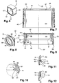
- Article 2 comprises a cover 26 comprising a cap 28, an insert 30 and a ring 32 respectively illustrated to figures 5 , 6 and 8 and forming separate pieces rigidly fixed to each other.
- the insert and the ring extend inside the cap. Only the cap 28 is visible when viewing the hood from the outside, as shown in FIG. figure 5 . This is a hood that is not permanently attached to the container being mounted movably on the latter. Thus, to obtain the product, the lid of the container is completely separated.
- the cap has in this case a side wall or skirt 34 of cylindrical shape with a generally square section in a plane perpendicular to the axis 22. This skirt is closed at its upper end by a flat wall 36.
- the cap is for example made in a relatively hard material such as a metal or a thermoplastic material.
- the insert 30 comprises a side wall or skirt 40 also of generally cylindrical shape of axis 22 with a generally square section in a plane perpendicular to this axis.
- the shape of this wall is not rigorously cylindrical because the insert 30 has a dimension transverse to the axis 22 which decreases as it gets closer to the top of the insert.
- the insert comprises a flat end wall 42 extending in a plane perpendicular to the axis 22.
- the upper face 44 of this wall extends at a distance from the upper end edge 46 of the wall 40.
- the wall 42 is thus slightly set back from this edge.
- the wall 42 has a large circular orifice 47 occupying the greater part of the location of this wall.
- the insert is made of a relatively hard material, for example a thermoplastic material.
- the ring 32 comprises a side wall or skirt 50 which has an outer face 51 of generally frustoconical shape with an axis 22 whose section decreases as it gets closer to the upper end of the ring.
- This end is formed by an end wall 52 which closes the skirt 50 at its upper edge protruding radially from this edge so that the wall 52 has a circumferential flange 54 projecting radially from the skirt 50 at this end.
- the wall 52 has, in plan, a generally square shape so that it has four corners 72.
- the ring 32 has a generally symmetrical shape about the axis 22.
- While the outer face 51 of the skirt 50 has a frustoconical shape, its inner face 56 has, on an upper portion contiguous to the end wall 52, a cylindrical shape of axis 22 with a circular section in a plane perpendicular to this axis.
- the inner face successively presents, from this section and up to the lower end edge 58 of the skirt 50, an upper cavity 60, an upper lip 62, a lower cavity 64 and a lip lower 66, these cavities and reliefs succeeding in this order by being contiguous.
- the lips 62, 66 and the cavities 60, 64 each have an annular shape, the cavities defining parallel grooves.
- the cavity 60 extends back from the cylindrical section of the face 56 in the radial direction to the axis 22, that is to say at a greater distance from the axis than this section.
- the upper lip 62 projects from the cylindrical section of the face 56, and consequently from the upper cavity 60, in the radial direction.
- the lip is delimited by two main faces, namely an upper face 68 of frustoconical shape with the narrowest cone section directed downwards and a lower face 70 of flat shape and perpendicular to the axis 22.
- the lower cavity 64 extends, like the cavity 60, recessed from the section 56 in the radial direction but further back than the latter.
- the height of this cavity measured parallel to the axis 22 is also greater than the height of the cavity 60 and even in this case equal to twice this height.
- the lower lip 66 extends back from the section 56 and therefore the lip 62, as well as the upper cavity 60 in the radial direction. However, it extends projecting from the lower cavity 64 which is contiguous thereto. It has a shape similar to that of the upper lip 62.
- the outer face 51 of the ring has an annular relief 72 illustrated in particular in FIG. figure 4 with an arcuate profile and projecting from this wall.
- the ring 32 is here made of a relatively soft material, that is to say softer or even less hard than that of the insert 30 and the cap 28. It is for example an organic or mineral elastomer such as silicone in this case. Alternatively, a thermoplastic elastomer could be used.
- the ring 32 is received in the cap 28 in a position such that its upper wall 52 abuts against the upper wall 36 of the cap by making a surface contact with the latter.
- the insert 30 is radially interposed at its upper portion between, on the one hand, the cap on the outside and, on the other hand, the ring internally.
- the skirt 50 of the ring which forms what may be called a sock, passes through the orifice 47 of the insert so that the wall 42 of the latter bears on its upper face 44 in the direction of the axis 22 against the flange 54 of the ring to maintain the wall 52 bearing against the top 36 of the cap.
- the edge 46 of the insert extends at a distance d, which is not zero, from the wall 36.
- the rim 54 of the ring has a thickness f greater than the distance separating the face 44 and the end 46, equal to the difference fd.
- the relief 72 of the sock extends against the wall 42 of the insert in the axial direction to reduce the risk of separation of the insert and the ring in the axial direction.
- the cap 28 has a similar relief 76 of annular shape and extending radially projecting from the inner face of the cap. This relief bears against the end edge of the skirt 40 of the insert in order to prevent the latter from sliding relative to the cap in the direction of the axis 22.
- the upper lip 62 is separated from the axis 22 by a distance shorter than the distance from the orifice 16 to this same axis. The lip therefore interferes with the orifice, as illustrated in FIGS. Figures 11 and 12 when the hood passes the nozzle, either when the hood is placed on the container or when it is removed.
- the cylindrical face 56 of the sock extends at a distance from the axis 22 substantially equal to that separating the orifice 16 of this same axis and preferably slightly less than this distance. So when the hood is in the position shown in the figure 2 in which it closes the container, the cylindrical section is in contact with the nozzle 14 which it closes the orifice 16 by making surface-to-surface contact with the latter.
- the sock being made of a relatively soft material, it forms at this point a shutter which closes the orifice effectively, even if the shape of the latter does not correspond to the rest to that of the sock.
- the figure 11 illustrates the position of the lip on the nozzle at the beginning of this scraping movement and the figure 12 illustrates the same elements at the end of the scraping motion.
- the lip When the lip has crossed the nozzle, it resumes elastically its original shape, while the nozzle comes into contact with the cylindrical portion of the face 56 and that its orifice is thus sealed by the sealing ring.
- This configuration remains as long as the hood is in the position shown in figure 2 in which it closes the container.
- the lip is first come scrape and wipe the orifice of the nozzle to remove the excess product, and after passing the orifice in front of the upper cavity 60, the hood has closed the door. orifice tightly thanks to the relatively soft nature of the material of the sock.
- the device 4 carries reliefs 76 and the cover has complementary cavities 78 forming means for clipping the cover on the device in order to immobilize the cover on the body when it closes the container.
- the upper lip 62 is again scrape the orifice 16 by deforming this time downwards and crushing the lower cavity 64.
- the scraping or wiping operations do not require deforming the cap 28 which is moreover essentially rigid.
- the invention does not modify the gesture of the user and does not require any particular action on his part. It is indeed during the movement to replace the cover on the container that takes place the cleaning of the orifice, then its shutter. These actions occur without the user being aware of them.
- the upper lip 62 is at a great distance from the lower edge of the hood. It is housed in the upper half of the latter and remains largely invisible in normal use except to look specifically in the hood.
- the relief 62 is separated from the lower end free edge of the cover by the lower portion of the internal face of the cap 28, the lower portion of the inner face of the insert and the lower lip 66 and the cavity 64 of the ring. It extends in radial projection of all these elements.
- the invention does not create any specific constraints on the shape and the materials used to make the article and, in particular, the container.
- the invention does not require placing the cover on the container in a particular angular position about the axis 22.
- any position of the cover on the container allows to obtain the aforementioned effects.
- the ring 32 is first mounted in the insert 30.
- the lower end of the ring is introduced into the orifice 47 of the insert until the edge 54 of the bearing ring in the direction of the axis 22 against the wall 42 which has when it crossed the relief 72.
- the assembly thus formed is then introduced into the interior of the cap until the wall 52 bears against the top of the cap and to cross with the insert the relief 76.
- the realization of the ring in a material such as an elastomer facilitates the manufacture thereof by molding. Indeed, the soft and deformable character imparted to this piece by the material makes it easy to demold even if it has undercut shapes. In addition, thanks to this relatively soft material, one can freely choose the shape of the face of the nozzle carrying the orifice, the material of the ring adapting in all cases to the chosen shape. The relative hardness of the material used to form the insert 30 promotes the robust attachment of the ring inside the cap 28.
- the device comprises, as before, a bottle provided with a hood which each have in a plane perpendicular to the vertical main axis 22 a generally square profile section. It can be expected that the four sides of the bottle and that the four faces of the hood are curved.
- the nozzle is integral with a pushbutton which is slidably mounted relative to the body along the axis 22.
- the pushbutton is not rotatable around of the axis 22 relative to the reservoir.
- the push button nozzle occupies a fixed position about the main axis being directed perpendicularly to one of the four faces of the bottle.
- the free end of the nozzle extends in a rectilinear direction perpendicular to the main axis 22.
- the dispensing orifice of the nozzle therefore extends in a plane parallel to one of the faces of the bottle.
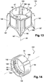
- the cover comprises a cap in which are housed an insert 130 and a ring 132 illustrated in the figures.
- the insert is made of a relatively rigid material while the ring is of flexible material.
- the orifice 47 of the insert is defined, as previously, by a cylindrical face 180 having for axis the axis 22 and whose section, in a plane perpendicular to this axis, is circular. This is the upper inner face of the insert.
- the insert 130 has here a lower inner surface 182 of frustoconical shape coaxial with the axis 22.
- the upper edge of this face has a circular shape. It corresponds to the smaller diameter section of the face.
- the frustoconical face 182 is separated from the cylindrical face 180 by a step 184 which forms a shoulder arranged so that the frustoconical face 182 extends at this point radially projecting from the cylindrical face 180 with reference to the axis 22.
- the outer faces of the insert generally occupying a rectangular parallelepiped, the intersection of these faces with the frustoconical face 182 is formed by four arches 186 in the form of hyperbola. These arches form the lower edge of the lower inner face 182. The intersections of these arches between them form points 187 which are in coincidence with the corners or corners of the hood.
- the section of the tapered face 182 is therefore narrowing from bottom to top. It forms a centering and guiding face when replacing the cover on the bottle over the push button. This face guides the latter in support towards the center of the hood.
- step 184 prevents the nozzle from catching the lower edge of the ring when closing the bottle with the cover.
- the ring 132 has a lip 62 which runs through the orifice of the nozzle by scraping or wiping it during closing.
- the device further comprises means for performing an angular indexing of the ring 132 relative to the insert 130 about the axis 22 at the time of their assembly one in the other.
- the ring 132 thus has one or more grooves 196 extending radially from the outer face 51 of the skirt.
- This face has, in this case, a cylindrical shape with circular section in a plane perpendicular to the axis 22.
- Each groove has a rectilinear shape parallel to the axis 22.
- the grooves are two in number and diametrically opposite on both sides of the axis.
- the insert 130 has in its inner upper face 180 ribs 198 having a shape and a disposition homologous to that of the grooves 196 to accommodate them when the ring is mounted in the insert.
- the upper portion 156 of the inner face of the skirt 50 has four flats 192 regularly distributed around the axis 22 so that the centers of two successive flats are separated by an angle of 90 ° around this axis .
- the flats opposite are parallel two by two while the successive flats are perpendicular to each other, each flat extending in a plane parallel to the axis 22 whose normal intersects this axis.
- the junction between the edges of the successive flats in the circumferential direction is effected by means of four facets 194 of cylindrical shape having an arcuate profile in a plane perpendicular to the axis 22.
- the four flats 192 are in coincidence around the axis 22 with the four outer faces of the cover, each flat being parallel to one of the faces. These flats locally increase the thickness of the sock and especially provide the nozzle a planar contact surface which is rectilinear in two directions respectively parallel and orthogonal to the axis 22 and rectilinear in a radial plane to this axis. This surface is therefore parallel to the plane of the free end of the nozzle.
- the device is arranged so that the cover can only occupy four different positions relative to the bottle and that in each of them, the faces of the bottle and the cover are in coincidence.
- the nozzle extending in a direction perpendicular to one of the main faces of the bottle, the nozzle is each time perpendicular to one of the flats 192 with which it comes into contact. The flats thus ensure the closure of the dispensing orifice of the nozzle regardless of the position of the cap on the bottle.
- the container can be given various shapes. Although it is advantageous to give some of the parts a symmetrical shape of revolution, this is not a necessity in the context of the invention.
- the pump is optional.
- the device may for example comprise a tube that is pressed or that is crushed to remove the product. It can be a pot with a movable piston.
- the cover may be formed of a single piece incorporating the cap, the insert and the ring, being manufactured by bi-injection of materials.
Landscapes
- Engineering & Computer Science (AREA)
- Mechanical Engineering (AREA)
- Closures For Containers (AREA)
- Containers And Packaging Bodies Having A Special Means To Remove Contents (AREA)
Claims (10)
- Vorrichtung (4) eines kosmetischen Produkts, die Folgendes umfasst:- einen Behälter, der eine Düse (14) mit einer Öffnung (16) zur Ausgabe eines Produkts, die sich am freien Ende der Düse befindet, aufweist; und- eine Abdeckkappe (26) mit einem internen Relief (62), das so angeordnet ist, dass es durch die Öffnung hindurchgeht, wenn man den Behälter mit der Abdeckkappe verschließt, und sich in einem Abstand von der Öffnung erstreckt, wenn die Abdeckkappe den Behälter verschließt, wobei die Abdeckkappe (26) so angeordnet ist, dass, wenn sie den Behälter verschließt, dieser gegen die Öffnung (16) drückt und sie verdeckt,wobei sich die Düse vorspringend auf einer Seite erstreckt, die dadurch gekennzeichnet ist, dass das Relief (62) so angeordnet ist, dass es vollständig in einiger Entfernung zu der Öffnung erstreckt, wenn die Abdeckkappe den Behälter verschließt, wobei das Relief zum Beispiel eine Lippe bildet.
- Vorrichtung nach dem vorangegangenen Anspruch, in welchem die Abdeckkappe (26) so angeordnet ist, dass sie die Öffnung (16) mittels einer Klappe aus flexiblem Material verschließt.
- Vorrichtung nach einem der vorangegangenen Ansprüche, in welchem das Relief (62) sich in einem Abstand eines Randes des freien Endpunkts der Abdeckkappe erstreckt.
- Vorrichtung nach einem der vorangegangenen Ansprüche, in welchem das Relief (62) um eine Achse (22) der Abdeckkappe (26) rotationssymmetrisch ist.
- Vorrichtung nach einem der vorangegangenen Ansprüche, in welchem die Abdeckkappe (26) mindestens eine Vertiefung (60, 64) benachbart zum Relief (62) aufweist, wobei es zum Beispiel zwei Vertiefungen geben kann, die sich bevorzugt jeweils über oder unter dem Relief (62) erstrecken.
- Vorrichtung nach einem der vorangegangenen Ansprüche, in welchem die Abdeckkappe (26) eine externe Kappe (28) und ein internes Element (32) umfasst, welches sich vollständig in der Kappe befindet und das Relief (62) trägt, wobei die Kappe und das Element getrennte Teile sind.
- Vorrichtung nach dem vorangegangenen Anspruch, in welchem das interne Element (32) in einem weniger harten Material als das Material der Kappe (28) ausgeführt ist, wobei das interne Element zum Beispiel aus Elastomer bestehen kann.
- Vorrichtung nach einem der Ansprüche 6 bis 7, in welchem die Abdeckkappe (26) ein Einsatzstück (30) umfasst, das ein von der Kappe (28) und dem internen Element (32) getrenntes Teil bildet und das Halten des internen Elements in der Kappe gewährleistet.
- Vorrichtung nach einem der vorangegangenen Ansprüche, die ein flüssiges oder dickflüssiges kosmetisches Produkt (6) enthält.
- Herstellungsvorgang einer Kappe (26) einer Vorrichtung nach einem der vorangegangenen Ansprüche, dadurch gekennzeichnet, dass man ein Einsatzstück (30) und ein internes Element (32) mit einem Relief (62) wie zum Beispiel einer Lippe zusammensetzt, danach die zusammengesetzten Teile in eine Kappe (28) einsetzt, um die Abdeckkappe zu bilden, so dass das Relief (62) ein internes Relief der Abdeckkappe bildet.
Applications Claiming Priority (2)
| Application Number | Priority Date | Filing Date | Title |
|---|---|---|---|
| FR0955578A FR2948861B1 (fr) | 2009-08-07 | 2009-08-07 | Dispositif de produit cosmetique presentant un orifice de distribution |
| PCT/FR2010/051634 WO2011015777A2 (fr) | 2009-08-07 | 2010-07-30 | Dispositif de produit cosmetique presentant un orifice de distribution |
Publications (2)
| Publication Number | Publication Date |
|---|---|
| EP2461716A2 EP2461716A2 (de) | 2012-06-13 |
| EP2461716B1 true EP2461716B1 (de) | 2018-10-24 |
Family
ID=42139031
Family Applications (1)
| Application Number | Title | Priority Date | Filing Date |
|---|---|---|---|
| EP10762961.0A Not-in-force EP2461716B1 (de) | 2009-08-07 | 2010-07-30 | Vorrichtung zur ausgabe eines kosmetikprodukts mit spenderöffnung |
Country Status (7)
| Country | Link |
|---|---|
| US (1) | US8590748B2 (de) |
| EP (1) | EP2461716B1 (de) |
| JP (1) | JP5797196B2 (de) |
| KR (1) | KR101749170B1 (de) |
| CN (1) | CN102686126B (de) |
| FR (1) | FR2948861B1 (de) |
| WO (1) | WO2011015777A2 (de) |
Families Citing this family (4)
| Publication number | Priority date | Publication date | Assignee | Title |
|---|---|---|---|---|
| EP3493918A1 (de) * | 2016-08-05 | 2019-06-12 | Unilever PLC | Verbesserungen an und im zusammenhang mit der bekleidungsauffrischung |
| JP6715140B2 (ja) * | 2016-09-13 | 2020-07-01 | 株式会社マンダム | 噴射容器、キャップ部材及び噴射製品 |
| CA3049913A1 (en) * | 2017-01-12 | 2018-07-19 | Becton Dickinson and Company Limited | Closed system stress resistant membrane |
| US11186413B1 (en) * | 2020-06-01 | 2021-11-30 | UmaCor Design LLC | Dripless cap and cup |
Citations (2)
| Publication number | Priority date | Publication date | Assignee | Title |
|---|---|---|---|---|
| EP0461894A2 (de) * | 1990-06-15 | 1991-12-18 | Calmar, Inc. | Schutzkappe und Wischer für die Auslassöffnung von Spendern |
| US20040050871A1 (en) * | 2002-06-28 | 2004-03-18 | L'oreal | Assembly for packaging and distribution of a product |
Family Cites Families (20)
| Publication number | Priority date | Publication date | Assignee | Title |
|---|---|---|---|---|
| US3655100A (en) * | 1970-03-13 | 1972-04-11 | Isral J Markowitz | Safety cover cap for an aerosol container |
| US3809300A (en) * | 1971-06-03 | 1974-05-07 | T Russell | Closure device for dispensing tubes |
| FR2605983B1 (fr) * | 1986-11-03 | 1988-12-02 | Cebal | Distributeur pour produit pateux et procede d'introduction de son piston a l'interieur de son corps tubulaire |
| FR2609967B1 (fr) | 1987-01-23 | 1989-08-04 | Cebal | Distributeur pour produit pateux a poussoir axial rotatif |
| US5094364A (en) * | 1990-06-15 | 1992-03-10 | Calmar Inc. | Protective overcap and wiper for dispenser discharge orifice |
| US5207785A (en) * | 1991-08-19 | 1993-05-04 | Calmar Inc. | Protector cap and wiper for dispenser discharge orifice |
| US5449094A (en) * | 1992-05-18 | 1995-09-12 | Sofab | Dispenser with plunging sleeve |
| GB9507185D0 (en) * | 1995-04-06 | 1995-05-31 | Incro Ltd | Spraying apparatus and nozzle devices |
| WO1997035499A1 (en) * | 1996-03-25 | 1997-10-02 | Sheffler Robert J | Liquid dispenser for products utilizing a brush-type applicator |
| JPH10337509A (ja) * | 1997-06-06 | 1998-12-22 | Shiseido Co Ltd | ディスペンサーのキャップ及びディスペンサー |
| EP1143824B1 (de) * | 1998-11-24 | 2005-07-27 | Coty S.A. | Verpackung und abdeckelement zum verpacken von kosmetischen oder pharmazeutischen zusammensetzungen |
| FR2786075B1 (fr) * | 1998-11-24 | 2001-02-02 | Coty Sa | Conditionnement etanche pour compositions cosmetiques et/ou pharmaceutiques |
| FR2796921B1 (fr) * | 1999-07-28 | 2001-10-05 | Valois Sa | Dispositif de distribution de produit fluide avec systeme d'obturation |
| FR2866819B1 (fr) | 2004-02-26 | 2006-03-31 | Techpack Int | Distributeur-applicateur typiquement a tete massante |
| FR2870215B1 (fr) * | 2004-05-17 | 2007-08-10 | Valois Sas | Capot pour tete de distribution de produit fluide. |
| US7510102B2 (en) * | 2006-02-22 | 2009-03-31 | Schmitt William H | Clog resistant actuator and overcap |
| KR200417222Y1 (ko) * | 2006-03-09 | 2006-05-25 | 김승섭 | 위조방지용 안전 캡 |
| US20070289603A1 (en) * | 2006-06-15 | 2007-12-20 | Hct Asia Ltd. | Cosmetics Dispenser with Automatic Closure |
| US20090008413A1 (en) * | 2007-04-17 | 2009-01-08 | Choi Hee Jin | Airless dispensing pump container with an airtight push down type nozzle head |
| CN107346765B (zh) * | 2016-05-04 | 2019-11-26 | 通用电气公司 | 桥臂电路封装组件及全桥电路封装组件 |
-
2009
- 2009-08-07 FR FR0955578A patent/FR2948861B1/fr not_active Expired - Fee Related
-
2010
- 2010-07-30 KR KR1020127006107A patent/KR101749170B1/ko active IP Right Grant
- 2010-07-30 EP EP10762961.0A patent/EP2461716B1/de not_active Not-in-force
- 2010-07-30 US US13/389,086 patent/US8590748B2/en not_active Expired - Fee Related
- 2010-07-30 JP JP2012523365A patent/JP5797196B2/ja not_active Expired - Fee Related
- 2010-07-30 CN CN201080045214.0A patent/CN102686126B/zh not_active Expired - Fee Related
- 2010-07-30 WO PCT/FR2010/051634 patent/WO2011015777A2/fr active Application Filing
Patent Citations (2)
| Publication number | Priority date | Publication date | Assignee | Title |
|---|---|---|---|---|
| EP0461894A2 (de) * | 1990-06-15 | 1991-12-18 | Calmar, Inc. | Schutzkappe und Wischer für die Auslassöffnung von Spendern |
| US20040050871A1 (en) * | 2002-06-28 | 2004-03-18 | L'oreal | Assembly for packaging and distribution of a product |
Also Published As
| Publication number | Publication date |
|---|---|
| WO2011015777A2 (fr) | 2011-02-10 |
| FR2948861A1 (fr) | 2011-02-11 |
| US20120187149A1 (en) | 2012-07-26 |
| KR101749170B1 (ko) | 2017-06-20 |
| CN102686126A (zh) | 2012-09-19 |
| FR2948861B1 (fr) | 2013-08-30 |
| WO2011015777A3 (fr) | 2011-04-28 |
| KR20120051736A (ko) | 2012-05-22 |
| JP2013500912A (ja) | 2013-01-10 |
| JP5797196B2 (ja) | 2015-10-21 |
| CN102686126B (zh) | 2015-08-12 |
| US8590748B2 (en) | 2013-11-26 |
| EP2461716A2 (de) | 2012-06-13 |
Similar Documents
| Publication | Publication Date | Title |
|---|---|---|
| EP2091836B1 (de) | Flüssigproduktspender | |
| EP2103542B1 (de) | Schutzvorrichtung für ein Verpackungssystem eines Produkts, insbesondere eines kosmetischen Produkts | |
| EP2739182B1 (de) | Flüssigmaterialspender | |
| EP2903907B1 (de) | Verpackungsvorrichtung und verfahren zu derer montage | |
| EP0929473B1 (de) | Verschluss für die ausgabeöffnung eines flüssigkeitsspenders | |
| EP1751023A1 (de) | Stopfen für den hals eines fluidproduktreservoirs | |
| EP2461716B1 (de) | Vorrichtung zur ausgabe eines kosmetikprodukts mit spenderöffnung | |
| EP3603817B1 (de) | Erleichterte montage und demontage einer pumpe in bezug auf einen reservoir | |
| EP2442914B1 (de) | Flüssigmaterialspender | |
| WO2015155472A1 (fr) | Flacon | |
| EP3094419A1 (de) | Flüssigproduktbehälter und spender mit solch einem behälter | |
| EP0329582B1 (de) | Spender für pastöse Produkte, versehen mit einem zur seitlichen Ausgabe dienenden axialen Betätigungskopf, und Verhüllungselement für seine Ausgabeöffnung | |
| FR2954754A1 (fr) | Capsule distributrice pour flacon de produit de consistance liquide ou visqueuse et flacon muni d'une telle capsule | |
| EP1651540A1 (de) | Fluidproduktabgabekopf | |
| EP2178415A2 (de) | Vorrichtung für ein kosmetikprodukt mit einem tank und einem applikator | |
| EP3181474B1 (de) | Tropf-stopp-plastikstopfen, insbesondere für mehr oder weniger viskose flüssigkeit | |
| FR3095133A1 (fr) | Distributeur de produit fluide | |
| EP3756769B1 (de) | Befestigungssystem eines verteilungsorgans auf dem gewindehals eines behälters | |
| WO2024022604A1 (fr) | Distributeur d'un produit fluide, recharge associée et réceptacle associé | |
| WO2024022605A1 (fr) | Recharge pour réceptacle de produit fluide et réceptacle associé | |
| FR2769005A1 (fr) | Capsule service pour recipient distributeur | |
| FR3102759A1 (fr) | Capsule avec valve intégrée pour récipient de stockage de produit, notamment d’un produit cosmétique | |
| FR3067014A1 (fr) | Assemblage d'un dispositif de distribution pour flacon | |
| FR2878698A1 (fr) | Distributeur d'un produit solide ou pateux | |
| WO2014202893A1 (fr) | Tete et procede de montage d'un organe de distribution sur un col de reservoir |
Legal Events
| Date | Code | Title | Description |
|---|---|---|---|
| PUAI | Public reference made under article 153(3) epc to a published international application that has entered the european phase |
Free format text: ORIGINAL CODE: 0009012 |
|
| 17P | Request for examination filed |
Effective date: 20120227 |
|
| AK | Designated contracting states |
Kind code of ref document: A2 Designated state(s): AL AT BE BG CH CY CZ DE DK EE ES FI FR GB GR HR HU IE IS IT LI LT LU LV MC MK MT NL NO PL PT RO SE SI SK SM TR |
|
| RIN1 | Information on inventor provided before grant (corrected) |
Inventor name: MATHIEU, NICOLAS Inventor name: POUCHAIN, JEAN-EUDES |
|
| DAX | Request for extension of the european patent (deleted) | ||
| STAA | Information on the status of an ep patent application or granted ep patent |
Free format text: STATUS: EXAMINATION IS IN PROGRESS |
|
| 17Q | First examination report despatched |
Effective date: 20170522 |
|
| GRAP | Despatch of communication of intention to grant a patent |
Free format text: ORIGINAL CODE: EPIDOSNIGR1 |
|
| STAA | Information on the status of an ep patent application or granted ep patent |
Free format text: STATUS: GRANT OF PATENT IS INTENDED |
|
| INTG | Intention to grant announced |
Effective date: 20180511 |
|
| GRAS | Grant fee paid |
Free format text: ORIGINAL CODE: EPIDOSNIGR3 |
|
| GRAA | (expected) grant |
Free format text: ORIGINAL CODE: 0009210 |
|
| STAA | Information on the status of an ep patent application or granted ep patent |
Free format text: STATUS: THE PATENT HAS BEEN GRANTED |
|
| AK | Designated contracting states |
Kind code of ref document: B1 Designated state(s): AL AT BE BG CH CY CZ DE DK EE ES FI FR GB GR HR HU IE IS IT LI LT LU LV MC MK MT NL NO PL PT RO SE SI SK SM TR |
|
| REG | Reference to a national code |
Ref country code: GB Ref legal event code: FG4D Free format text: NOT ENGLISH |
|
| REG | Reference to a national code |
Ref country code: CH Ref legal event code: EP |
|
| REG | Reference to a national code |
Ref country code: IE Ref legal event code: FG4D Free format text: LANGUAGE OF EP DOCUMENT: FRENCH |
|
| REG | Reference to a national code |
Ref country code: AT Ref legal event code: REF Ref document number: 1055647 Country of ref document: AT Kind code of ref document: T Effective date: 20181115 |
|
| REG | Reference to a national code |
Ref country code: DE Ref legal event code: R096 Ref document number: 602010054601 Country of ref document: DE |
|
| REG | Reference to a national code |
Ref country code: NL Ref legal event code: MP Effective date: 20181024 |
|
| REG | Reference to a national code |
Ref country code: LT Ref legal event code: MG4D |
|
| REG | Reference to a national code |
Ref country code: AT Ref legal event code: MK05 Ref document number: 1055647 Country of ref document: AT Kind code of ref document: T Effective date: 20181024 |
|
| PG25 | Lapsed in a contracting state [announced via postgrant information from national office to epo] |
Ref country code: NL Free format text: LAPSE BECAUSE OF FAILURE TO SUBMIT A TRANSLATION OF THE DESCRIPTION OR TO PAY THE FEE WITHIN THE PRESCRIBED TIME-LIMIT Effective date: 20181024 |
|
| PG25 | Lapsed in a contracting state [announced via postgrant information from national office to epo] |
Ref country code: IS Free format text: LAPSE BECAUSE OF FAILURE TO SUBMIT A TRANSLATION OF THE DESCRIPTION OR TO PAY THE FEE WITHIN THE PRESCRIBED TIME-LIMIT Effective date: 20190224 Ref country code: FI Free format text: LAPSE BECAUSE OF FAILURE TO SUBMIT A TRANSLATION OF THE DESCRIPTION OR TO PAY THE FEE WITHIN THE PRESCRIBED TIME-LIMIT Effective date: 20181024 Ref country code: LT Free format text: LAPSE BECAUSE OF FAILURE TO SUBMIT A TRANSLATION OF THE DESCRIPTION OR TO PAY THE FEE WITHIN THE PRESCRIBED TIME-LIMIT Effective date: 20181024 Ref country code: HR Free format text: LAPSE BECAUSE OF FAILURE TO SUBMIT A TRANSLATION OF THE DESCRIPTION OR TO PAY THE FEE WITHIN THE PRESCRIBED TIME-LIMIT Effective date: 20181024 Ref country code: PL Free format text: LAPSE BECAUSE OF FAILURE TO SUBMIT A TRANSLATION OF THE DESCRIPTION OR TO PAY THE FEE WITHIN THE PRESCRIBED TIME-LIMIT Effective date: 20181024 Ref country code: BG Free format text: LAPSE BECAUSE OF FAILURE TO SUBMIT A TRANSLATION OF THE DESCRIPTION OR TO PAY THE FEE WITHIN THE PRESCRIBED TIME-LIMIT Effective date: 20190124 Ref country code: LV Free format text: LAPSE BECAUSE OF FAILURE TO SUBMIT A TRANSLATION OF THE DESCRIPTION OR TO PAY THE FEE WITHIN THE PRESCRIBED TIME-LIMIT Effective date: 20181024 Ref country code: ES Free format text: LAPSE BECAUSE OF FAILURE TO SUBMIT A TRANSLATION OF THE DESCRIPTION OR TO PAY THE FEE WITHIN THE PRESCRIBED TIME-LIMIT Effective date: 20181024 Ref country code: NO Free format text: LAPSE BECAUSE OF FAILURE TO SUBMIT A TRANSLATION OF THE DESCRIPTION OR TO PAY THE FEE WITHIN THE PRESCRIBED TIME-LIMIT Effective date: 20190124 Ref country code: AT Free format text: LAPSE BECAUSE OF FAILURE TO SUBMIT A TRANSLATION OF THE DESCRIPTION OR TO PAY THE FEE WITHIN THE PRESCRIBED TIME-LIMIT Effective date: 20181024 |
|
| PG25 | Lapsed in a contracting state [announced via postgrant information from national office to epo] |
Ref country code: PT Free format text: LAPSE BECAUSE OF FAILURE TO SUBMIT A TRANSLATION OF THE DESCRIPTION OR TO PAY THE FEE WITHIN THE PRESCRIBED TIME-LIMIT Effective date: 20190224 Ref country code: AL Free format text: LAPSE BECAUSE OF FAILURE TO SUBMIT A TRANSLATION OF THE DESCRIPTION OR TO PAY THE FEE WITHIN THE PRESCRIBED TIME-LIMIT Effective date: 20181024 Ref country code: GR Free format text: LAPSE BECAUSE OF FAILURE TO SUBMIT A TRANSLATION OF THE DESCRIPTION OR TO PAY THE FEE WITHIN THE PRESCRIBED TIME-LIMIT Effective date: 20190125 Ref country code: SE Free format text: LAPSE BECAUSE OF FAILURE TO SUBMIT A TRANSLATION OF THE DESCRIPTION OR TO PAY THE FEE WITHIN THE PRESCRIBED TIME-LIMIT Effective date: 20181024 |
|
| REG | Reference to a national code |
Ref country code: DE Ref legal event code: R097 Ref document number: 602010054601 Country of ref document: DE |
|
| PG25 | Lapsed in a contracting state [announced via postgrant information from national office to epo] |
Ref country code: IT Free format text: LAPSE BECAUSE OF FAILURE TO SUBMIT A TRANSLATION OF THE DESCRIPTION OR TO PAY THE FEE WITHIN THE PRESCRIBED TIME-LIMIT Effective date: 20181024 Ref country code: CZ Free format text: LAPSE BECAUSE OF FAILURE TO SUBMIT A TRANSLATION OF THE DESCRIPTION OR TO PAY THE FEE WITHIN THE PRESCRIBED TIME-LIMIT Effective date: 20181024 Ref country code: DK Free format text: LAPSE BECAUSE OF FAILURE TO SUBMIT A TRANSLATION OF THE DESCRIPTION OR TO PAY THE FEE WITHIN THE PRESCRIBED TIME-LIMIT Effective date: 20181024 |
|
| PG25 | Lapsed in a contracting state [announced via postgrant information from national office to epo] |
Ref country code: SK Free format text: LAPSE BECAUSE OF FAILURE TO SUBMIT A TRANSLATION OF THE DESCRIPTION OR TO PAY THE FEE WITHIN THE PRESCRIBED TIME-LIMIT Effective date: 20181024 Ref country code: RO Free format text: LAPSE BECAUSE OF FAILURE TO SUBMIT A TRANSLATION OF THE DESCRIPTION OR TO PAY THE FEE WITHIN THE PRESCRIBED TIME-LIMIT Effective date: 20181024 Ref country code: EE Free format text: LAPSE BECAUSE OF FAILURE TO SUBMIT A TRANSLATION OF THE DESCRIPTION OR TO PAY THE FEE WITHIN THE PRESCRIBED TIME-LIMIT Effective date: 20181024 Ref country code: SM Free format text: LAPSE BECAUSE OF FAILURE TO SUBMIT A TRANSLATION OF THE DESCRIPTION OR TO PAY THE FEE WITHIN THE PRESCRIBED TIME-LIMIT Effective date: 20181024 |
|
| PLBE | No opposition filed within time limit |
Free format text: ORIGINAL CODE: 0009261 |
|
| STAA | Information on the status of an ep patent application or granted ep patent |
Free format text: STATUS: NO OPPOSITION FILED WITHIN TIME LIMIT |
|
| 26N | No opposition filed |
Effective date: 20190725 |
|
| PG25 | Lapsed in a contracting state [announced via postgrant information from national office to epo] |
Ref country code: SI Free format text: LAPSE BECAUSE OF FAILURE TO SUBMIT A TRANSLATION OF THE DESCRIPTION OR TO PAY THE FEE WITHIN THE PRESCRIBED TIME-LIMIT Effective date: 20181024 |
|
| PGFP | Annual fee paid to national office [announced via postgrant information from national office to epo] |
Ref country code: DE Payment date: 20190719 Year of fee payment: 10 Ref country code: FR Payment date: 20190730 Year of fee payment: 10 |
|
| PGFP | Annual fee paid to national office [announced via postgrant information from national office to epo] |
Ref country code: GB Payment date: 20190719 Year of fee payment: 10 |
|
| PG25 | Lapsed in a contracting state [announced via postgrant information from national office to epo] |
Ref country code: MC Free format text: LAPSE BECAUSE OF FAILURE TO SUBMIT A TRANSLATION OF THE DESCRIPTION OR TO PAY THE FEE WITHIN THE PRESCRIBED TIME-LIMIT Effective date: 20181024 |
|
| REG | Reference to a national code |
Ref country code: CH Ref legal event code: PL |
|
| PG25 | Lapsed in a contracting state [announced via postgrant information from national office to epo] |
Ref country code: TR Free format text: LAPSE BECAUSE OF FAILURE TO SUBMIT A TRANSLATION OF THE DESCRIPTION OR TO PAY THE FEE WITHIN THE PRESCRIBED TIME-LIMIT Effective date: 20181024 |
|
| REG | Reference to a national code |
Ref country code: BE Ref legal event code: MM Effective date: 20190731 |
|
| PG25 | Lapsed in a contracting state [announced via postgrant information from national office to epo] |
Ref country code: LU Free format text: LAPSE BECAUSE OF NON-PAYMENT OF DUE FEES Effective date: 20190730 Ref country code: LI Free format text: LAPSE BECAUSE OF NON-PAYMENT OF DUE FEES Effective date: 20190731 Ref country code: CH Free format text: LAPSE BECAUSE OF NON-PAYMENT OF DUE FEES Effective date: 20190731 Ref country code: BE Free format text: LAPSE BECAUSE OF NON-PAYMENT OF DUE FEES Effective date: 20190731 |
|
| PG25 | Lapsed in a contracting state [announced via postgrant information from national office to epo] |
Ref country code: IE Free format text: LAPSE BECAUSE OF NON-PAYMENT OF DUE FEES Effective date: 20190730 |
|
| REG | Reference to a national code |
Ref country code: DE Ref legal event code: R119 Ref document number: 602010054601 Country of ref document: DE |
|
| GBPC | Gb: european patent ceased through non-payment of renewal fee |
Effective date: 20200730 |
|
| PG25 | Lapsed in a contracting state [announced via postgrant information from national office to epo] |
Ref country code: GB Free format text: LAPSE BECAUSE OF NON-PAYMENT OF DUE FEES Effective date: 20200730 Ref country code: FR Free format text: LAPSE BECAUSE OF NON-PAYMENT OF DUE FEES Effective date: 20200731 |
|
| PG25 | Lapsed in a contracting state [announced via postgrant information from national office to epo] |
Ref country code: CY Free format text: LAPSE BECAUSE OF FAILURE TO SUBMIT A TRANSLATION OF THE DESCRIPTION OR TO PAY THE FEE WITHIN THE PRESCRIBED TIME-LIMIT Effective date: 20181024 Ref country code: DE Free format text: LAPSE BECAUSE OF NON-PAYMENT OF DUE FEES Effective date: 20210202 |
|
| PG25 | Lapsed in a contracting state [announced via postgrant information from national office to epo] |
Ref country code: HU Free format text: LAPSE BECAUSE OF FAILURE TO SUBMIT A TRANSLATION OF THE DESCRIPTION OR TO PAY THE FEE WITHIN THE PRESCRIBED TIME-LIMIT; INVALID AB INITIO Effective date: 20100730 Ref country code: MT Free format text: LAPSE BECAUSE OF FAILURE TO SUBMIT A TRANSLATION OF THE DESCRIPTION OR TO PAY THE FEE WITHIN THE PRESCRIBED TIME-LIMIT Effective date: 20181024 |
|
| PG25 | Lapsed in a contracting state [announced via postgrant information from national office to epo] |
Ref country code: MK Free format text: LAPSE BECAUSE OF FAILURE TO SUBMIT A TRANSLATION OF THE DESCRIPTION OR TO PAY THE FEE WITHIN THE PRESCRIBED TIME-LIMIT Effective date: 20181024 |