EP2461716B1 - Dispositif de produit cosmetique presentant un orifice de distribution - Google Patents
Dispositif de produit cosmetique presentant un orifice de distribution Download PDFInfo
- Publication number
- EP2461716B1 EP2461716B1 EP10762961.0A EP10762961A EP2461716B1 EP 2461716 B1 EP2461716 B1 EP 2461716B1 EP 10762961 A EP10762961 A EP 10762961A EP 2461716 B1 EP2461716 B1 EP 2461716B1
- Authority
- EP
- European Patent Office
- Prior art keywords
- cap
- relief
- orifice
- nozzle
- cover
- Prior art date
- Legal status (The legal status is an assumption and is not a legal conclusion. Google has not performed a legal analysis and makes no representation as to the accuracy of the status listed.)
- Not-in-force
Links
Images

Classifications
-
- A—HUMAN NECESSITIES
- A45—HAND OR TRAVELLING ARTICLES
- A45D—HAIRDRESSING OR SHAVING EQUIPMENT; EQUIPMENT FOR COSMETICS OR COSMETIC TREATMENTS, e.g. FOR MANICURING OR PEDICURING
- A45D34/00—Containers or accessories specially adapted for handling liquid toiletry or cosmetic substances, e.g. perfumes
- A45D34/04—Appliances specially adapted for applying liquid, e.g. using roller or ball
-
- A—HUMAN NECESSITIES
- A45—HAND OR TRAVELLING ARTICLES
- A45D—HAIRDRESSING OR SHAVING EQUIPMENT; EQUIPMENT FOR COSMETICS OR COSMETIC TREATMENTS, e.g. FOR MANICURING OR PEDICURING
- A45D34/00—Containers or accessories specially adapted for handling liquid toiletry or cosmetic substances, e.g. perfumes
- A45D34/02—Scent flasks, e.g. with evaporator
-
- A—HUMAN NECESSITIES
- A45—HAND OR TRAVELLING ARTICLES
- A45D—HAIRDRESSING OR SHAVING EQUIPMENT; EQUIPMENT FOR COSMETICS OR COSMETIC TREATMENTS, e.g. FOR MANICURING OR PEDICURING
- A45D40/00—Casings or accessories specially adapted for storing or handling solid or pasty toiletry or cosmetic substances, e.g. shaving soaps or lipsticks
- A45D40/26—Appliances specially adapted for applying pasty paint, e.g. using roller, using a ball
- A45D40/262—Appliances specially adapted for applying pasty paint, e.g. using roller, using a ball using a brush or the like
- A45D40/265—Appliances specially adapted for applying pasty paint, e.g. using roller, using a ball using a brush or the like connected to the cap of the container
- A45D40/267—Appliances specially adapted for applying pasty paint, e.g. using roller, using a ball using a brush or the like connected to the cap of the container comprising a wiper
-
- B—PERFORMING OPERATIONS; TRANSPORTING
- B65—CONVEYING; PACKING; STORING; HANDLING THIN OR FILAMENTARY MATERIAL
- B65D—CONTAINERS FOR STORAGE OR TRANSPORT OF ARTICLES OR MATERIALS, e.g. BAGS, BARRELS, BOTTLES, BOXES, CANS, CARTONS, CRATES, DRUMS, JARS, TANKS, HOPPERS, FORWARDING CONTAINERS; ACCESSORIES, CLOSURES, OR FITTINGS THEREFOR; PACKAGING ELEMENTS; PACKAGES
- B65D41/00—Caps, e.g. crown caps or crown seals, i.e. members having parts arranged for engagement with the external periphery of a neck or wall defining a pouring opening or discharge aperture; Protective cap-like covers for closure members, e.g. decorative covers of metal foil or paper
- B65D41/02—Caps or cap-like covers without lines of weakness, tearing strips, tags, or like opening or removal devices
- B65D41/023—Caps or cap-like covers without lines of weakness, tearing strips, tags, or like opening or removal devices with integral internal sealing means
-
- A—HUMAN NECESSITIES
- A45—HAND OR TRAVELLING ARTICLES
- A45D—HAIRDRESSING OR SHAVING EQUIPMENT; EQUIPMENT FOR COSMETICS OR COSMETIC TREATMENTS, e.g. FOR MANICURING OR PEDICURING
- A45D33/00—Containers or accessories specially adapted for handling powdery toiletry or cosmetic substances
- A45D2033/001—Accessories
-
- A—HUMAN NECESSITIES
- A45—HAND OR TRAVELLING ARTICLES
- A45D—HAIRDRESSING OR SHAVING EQUIPMENT; EQUIPMENT FOR COSMETICS OR COSMETIC TREATMENTS, e.g. FOR MANICURING OR PEDICURING
- A45D34/00—Containers or accessories specially adapted for handling liquid toiletry or cosmetic substances, e.g. perfumes
- A45D2034/002—Accessories
-
- A—HUMAN NECESSITIES
- A45—HAND OR TRAVELLING ARTICLES
- A45D—HAIRDRESSING OR SHAVING EQUIPMENT; EQUIPMENT FOR COSMETICS OR COSMETIC TREATMENTS, e.g. FOR MANICURING OR PEDICURING
- A45D34/00—Containers or accessories specially adapted for handling liquid toiletry or cosmetic substances, e.g. perfumes
- A45D2034/007—Containers or accessories specially adapted for handling liquid toiletry or cosmetic substances, e.g. perfumes with special decorative arrangements or form
-
- A—HUMAN NECESSITIES
- A45—HAND OR TRAVELLING ARTICLES
- A45D—HAIRDRESSING OR SHAVING EQUIPMENT; EQUIPMENT FOR COSMETICS OR COSMETIC TREATMENTS, e.g. FOR MANICURING OR PEDICURING
- A45D40/00—Casings or accessories specially adapted for storing or handling solid or pasty toiletry or cosmetic substances, e.g. shaving soaps or lipsticks
- A45D2040/0006—Accessories
-
- A—HUMAN NECESSITIES
- A45—HAND OR TRAVELLING ARTICLES
- A45D—HAIRDRESSING OR SHAVING EQUIPMENT; EQUIPMENT FOR COSMETICS OR COSMETIC TREATMENTS, e.g. FOR MANICURING OR PEDICURING
- A45D2200/00—Details not otherwise provided for in A45D
- A45D2200/05—Details of containers
- A45D2200/051—Airtight containers
-
- Y—GENERAL TAGGING OF NEW TECHNOLOGICAL DEVELOPMENTS; GENERAL TAGGING OF CROSS-SECTIONAL TECHNOLOGIES SPANNING OVER SEVERAL SECTIONS OF THE IPC; TECHNICAL SUBJECTS COVERED BY FORMER USPC CROSS-REFERENCE ART COLLECTIONS [XRACs] AND DIGESTS
- Y10—TECHNICAL SUBJECTS COVERED BY FORMER USPC
- Y10T—TECHNICAL SUBJECTS COVERED BY FORMER US CLASSIFICATION
- Y10T29/00—Metal working
- Y10T29/49—Method of mechanical manufacture
- Y10T29/49826—Assembling or joining
Definitions
- the invention relates to cosmetic product devices comprising a container.
- Articles containing a cosmetic product in liquid or viscous form, the distribution of which is carried out through the orifice of a nozzle, are known. Means such as a pump allow, on command, to distribute product through the orifice.
- the assembly can be covered with a cover which has the function of avoiding contact between the orifice and the elements outside the article.
- a device of this type is for example described in the application EP-0 277 893 .
- this product fraction forms a focus that can be contaminated in contact with the external environment.
- the appearance of the product deposit thus formed is unattractive when the user removes the cover to obtain the product. This is particularly the case when the product dries in contact with the ambient air. And this deposit can be found mixed with the dose of clean product distributed through the orifice.
- EP-A2-0 461 894 discloses the preamble of claim 1.
- An object of the invention is to improve the cleaning of the nozzle.
- the relief eliminates from the orifice the product which exceeded it at the end of use and before the hood reaches its position in which it closes the container. Any remaining product protruding on the orifice is thereby removed from the nozzle. Therefore, when the user removes the cover, it finds a nozzle whose orifice is free of product and has a satisfactory appearance.
- the hood scrape or wipe the orifice not only does the hood scrape or wipe the orifice, but it then closes it to limit the communication between the product in the container and the external environment and thus preserve the properties of this product .
- the invention has the effect of further reducing the amount of product in contact with the external environment and thus to maintain its attractive appearance at the orifice of the nozzle in this type of device during the life of the article.
- the cover is arranged to close the orifice by means of a flexible material shutter.
- the relief extends away from a free end edge of the hood.
- the relief has a symmetry of revolution about an axis of the hood.
- the cover can be set up on the container without requiring a certain angular positioning of one relative to the other around the main axis of the container.
- the hood may occupy a position offset by a quarter of a turn from its original position.
- the relief performs scraping or wiping preserving the cleanliness of the orifice.
- the cover has at least one cavity contiguous to the relief, the cavities being for example two in number and preferably extending respectively above and below the relief.
- this cavity is a reservoir in which can be housed the product that the relief has removed from the orifice. This prevents the product from coming to occupy an uncontrolled position inside the hood, where it could subsequently fall or come into contact with the user or with another part of the container.
- the cavity When the cavity is a lower cavity, it receives the product that results from the journey made when the cover is placed on the container. If the cavity is an upper cavity, it receives the product that is removed by the relief on the orifice when removing the container cover.
- the cap comprises an outer cap and an inner member fully housed in the cap and bearing the relief, the cap and the element forming separate pieces.
- each of these pieces can be produced in materials that are different from one another and that are best able to fulfill their role.
- the inner element is made of a material that is less hard than a material of the cap, the inner element being made for example of elastomer.
- the cap has an aesthetic function in particular as it contributes greatly to the overall appearance of the device.
- the cap for example, in a relatively hard plastic material, the aspect of which can easily be controlled (surface condition, possible printing, painting, etc.).
- the element carrying the relief in a relatively soft material such as an elastomer so that the relief performs an effective scraping or wiping.
- the cover comprises an insert forming a separate part of the cap and the inner member and ensuring the maintenance of the inner member in the cap.
- the device comprises a liquid or pasty cosmetic product.
- the device comprises a product dispensing mechanism, such as a pump.
- Also provided according to the invention is a method of manufacturing a cover of an article according to the invention, in which an insert is assembled and an inner element bearing a relief such as a lip, and then the assembly is introduced into a cap to form the hood so that the relief forms an internal relief of the hood.
- FIGS. FIG. 2 illustrates a device 4 containing a cosmetic product 6.
- the latter may be a care product and / or makeup for the face or body or a pharmaceutical product such as a drug. It is a liquid or pasty product and distributed to the user in this form by the article.
- This product may be formed by an aqueous solution, a fat solution or an emulsion.
- the article 2 comprises a body constituting here a bottle which encloses a reservoir 8 of the product 6.
- This reservoir is surmounted by a mechanism 10 for dispensing the product through a nozzle 14 extending at the upper end of the body.
- the nozzle has a port 16 for dispensing the product.
- the mechanism 10 for dispensing the product through the orifice comprises a pump capable of extracting the product from the reservoir and conveying it to the orifice 16. This pump is of a type known in itself. and will not be described in detail here.
- the nozzle 14 is integral with a push button 18 which is slidably mounted relative to the body along a vertical main axis 22 of the article 2.
- the article is arranged so that, when the user exerts pressure on the upper face 20 of the button forming the top of the body, this pressure causes the descent of the button 18 inside the body and at the same time the administration of a dose of product by means of the pump through the orifice 16.
- the detail of the circuit connecting the reservoir 8, the pump 10 and the orifice is of a conventional type and has not been illustrated.
- the push-button 18 here has a generally symmetrical shape of revolution about the axis 22. It has in particular a cylindrical lateral face 24 with a circular cross-section in a plane perpendicular to the axis 22.
- the nozzle extends in projection from this face on one side of the button, the orifice being provided at the free end of the nozzle, formed by a generally cylindrical face of axis 22. It is provided here that the pushbutton 18 is rotatable around the axis 22 relative to the tank without this feature is nevertheless an obligation.
- Article 2 comprises a cover 26 comprising a cap 28, an insert 30 and a ring 32 respectively illustrated to figures 5 , 6 and 8 and forming separate pieces rigidly fixed to each other.
- the insert and the ring extend inside the cap. Only the cap 28 is visible when viewing the hood from the outside, as shown in FIG. figure 5 . This is a hood that is not permanently attached to the container being mounted movably on the latter. Thus, to obtain the product, the lid of the container is completely separated.
- the cap has in this case a side wall or skirt 34 of cylindrical shape with a generally square section in a plane perpendicular to the axis 22. This skirt is closed at its upper end by a flat wall 36.
- the cap is for example made in a relatively hard material such as a metal or a thermoplastic material.
- the insert 30 comprises a side wall or skirt 40 also of generally cylindrical shape of axis 22 with a generally square section in a plane perpendicular to this axis.
- the shape of this wall is not rigorously cylindrical because the insert 30 has a dimension transverse to the axis 22 which decreases as it gets closer to the top of the insert.
- the insert comprises a flat end wall 42 extending in a plane perpendicular to the axis 22.
- the upper face 44 of this wall extends at a distance from the upper end edge 46 of the wall 40.
- the wall 42 is thus slightly set back from this edge.
- the wall 42 has a large circular orifice 47 occupying the greater part of the location of this wall.
- the insert is made of a relatively hard material, for example a thermoplastic material.
- the ring 32 comprises a side wall or skirt 50 which has an outer face 51 of generally frustoconical shape with an axis 22 whose section decreases as it gets closer to the upper end of the ring.
- This end is formed by an end wall 52 which closes the skirt 50 at its upper edge protruding radially from this edge so that the wall 52 has a circumferential flange 54 projecting radially from the skirt 50 at this end.
- the wall 52 has, in plan, a generally square shape so that it has four corners 72.
- the ring 32 has a generally symmetrical shape about the axis 22.
- While the outer face 51 of the skirt 50 has a frustoconical shape, its inner face 56 has, on an upper portion contiguous to the end wall 52, a cylindrical shape of axis 22 with a circular section in a plane perpendicular to this axis.
- the inner face successively presents, from this section and up to the lower end edge 58 of the skirt 50, an upper cavity 60, an upper lip 62, a lower cavity 64 and a lip lower 66, these cavities and reliefs succeeding in this order by being contiguous.
- the lips 62, 66 and the cavities 60, 64 each have an annular shape, the cavities defining parallel grooves.
- the cavity 60 extends back from the cylindrical section of the face 56 in the radial direction to the axis 22, that is to say at a greater distance from the axis than this section.
- the upper lip 62 projects from the cylindrical section of the face 56, and consequently from the upper cavity 60, in the radial direction.
- the lip is delimited by two main faces, namely an upper face 68 of frustoconical shape with the narrowest cone section directed downwards and a lower face 70 of flat shape and perpendicular to the axis 22.
- the lower cavity 64 extends, like the cavity 60, recessed from the section 56 in the radial direction but further back than the latter.
- the height of this cavity measured parallel to the axis 22 is also greater than the height of the cavity 60 and even in this case equal to twice this height.
- the lower lip 66 extends back from the section 56 and therefore the lip 62, as well as the upper cavity 60 in the radial direction. However, it extends projecting from the lower cavity 64 which is contiguous thereto. It has a shape similar to that of the upper lip 62.
- the outer face 51 of the ring has an annular relief 72 illustrated in particular in FIG. figure 4 with an arcuate profile and projecting from this wall.
- the ring 32 is here made of a relatively soft material, that is to say softer or even less hard than that of the insert 30 and the cap 28. It is for example an organic or mineral elastomer such as silicone in this case. Alternatively, a thermoplastic elastomer could be used.
- the ring 32 is received in the cap 28 in a position such that its upper wall 52 abuts against the upper wall 36 of the cap by making a surface contact with the latter.
- the insert 30 is radially interposed at its upper portion between, on the one hand, the cap on the outside and, on the other hand, the ring internally.
- the skirt 50 of the ring which forms what may be called a sock, passes through the orifice 47 of the insert so that the wall 42 of the latter bears on its upper face 44 in the direction of the axis 22 against the flange 54 of the ring to maintain the wall 52 bearing against the top 36 of the cap.
- the edge 46 of the insert extends at a distance d, which is not zero, from the wall 36.
- the rim 54 of the ring has a thickness f greater than the distance separating the face 44 and the end 46, equal to the difference fd.
- the relief 72 of the sock extends against the wall 42 of the insert in the axial direction to reduce the risk of separation of the insert and the ring in the axial direction.
- the cap 28 has a similar relief 76 of annular shape and extending radially projecting from the inner face of the cap. This relief bears against the end edge of the skirt 40 of the insert in order to prevent the latter from sliding relative to the cap in the direction of the axis 22.
- the upper lip 62 is separated from the axis 22 by a distance shorter than the distance from the orifice 16 to this same axis. The lip therefore interferes with the orifice, as illustrated in FIGS. Figures 11 and 12 when the hood passes the nozzle, either when the hood is placed on the container or when it is removed.
- the cylindrical face 56 of the sock extends at a distance from the axis 22 substantially equal to that separating the orifice 16 of this same axis and preferably slightly less than this distance. So when the hood is in the position shown in the figure 2 in which it closes the container, the cylindrical section is in contact with the nozzle 14 which it closes the orifice 16 by making surface-to-surface contact with the latter.
- the sock being made of a relatively soft material, it forms at this point a shutter which closes the orifice effectively, even if the shape of the latter does not correspond to the rest to that of the sock.
- the figure 11 illustrates the position of the lip on the nozzle at the beginning of this scraping movement and the figure 12 illustrates the same elements at the end of the scraping motion.
- the lip When the lip has crossed the nozzle, it resumes elastically its original shape, while the nozzle comes into contact with the cylindrical portion of the face 56 and that its orifice is thus sealed by the sealing ring.
- This configuration remains as long as the hood is in the position shown in figure 2 in which it closes the container.
- the lip is first come scrape and wipe the orifice of the nozzle to remove the excess product, and after passing the orifice in front of the upper cavity 60, the hood has closed the door. orifice tightly thanks to the relatively soft nature of the material of the sock.
- the device 4 carries reliefs 76 and the cover has complementary cavities 78 forming means for clipping the cover on the device in order to immobilize the cover on the body when it closes the container.
- the upper lip 62 is again scrape the orifice 16 by deforming this time downwards and crushing the lower cavity 64.
- the scraping or wiping operations do not require deforming the cap 28 which is moreover essentially rigid.
- the invention does not modify the gesture of the user and does not require any particular action on his part. It is indeed during the movement to replace the cover on the container that takes place the cleaning of the orifice, then its shutter. These actions occur without the user being aware of them.
- the upper lip 62 is at a great distance from the lower edge of the hood. It is housed in the upper half of the latter and remains largely invisible in normal use except to look specifically in the hood.
- the relief 62 is separated from the lower end free edge of the cover by the lower portion of the internal face of the cap 28, the lower portion of the inner face of the insert and the lower lip 66 and the cavity 64 of the ring. It extends in radial projection of all these elements.
- the invention does not create any specific constraints on the shape and the materials used to make the article and, in particular, the container.
- the invention does not require placing the cover on the container in a particular angular position about the axis 22.
- any position of the cover on the container allows to obtain the aforementioned effects.
- the ring 32 is first mounted in the insert 30.
- the lower end of the ring is introduced into the orifice 47 of the insert until the edge 54 of the bearing ring in the direction of the axis 22 against the wall 42 which has when it crossed the relief 72.
- the assembly thus formed is then introduced into the interior of the cap until the wall 52 bears against the top of the cap and to cross with the insert the relief 76.
- the realization of the ring in a material such as an elastomer facilitates the manufacture thereof by molding. Indeed, the soft and deformable character imparted to this piece by the material makes it easy to demold even if it has undercut shapes. In addition, thanks to this relatively soft material, one can freely choose the shape of the face of the nozzle carrying the orifice, the material of the ring adapting in all cases to the chosen shape. The relative hardness of the material used to form the insert 30 promotes the robust attachment of the ring inside the cap 28.
- the device comprises, as before, a bottle provided with a hood which each have in a plane perpendicular to the vertical main axis 22 a generally square profile section. It can be expected that the four sides of the bottle and that the four faces of the hood are curved.
- the nozzle is integral with a pushbutton which is slidably mounted relative to the body along the axis 22.
- the pushbutton is not rotatable around of the axis 22 relative to the reservoir.
- the push button nozzle occupies a fixed position about the main axis being directed perpendicularly to one of the four faces of the bottle.
- the free end of the nozzle extends in a rectilinear direction perpendicular to the main axis 22.
- the dispensing orifice of the nozzle therefore extends in a plane parallel to one of the faces of the bottle.
- the cover comprises a cap in which are housed an insert 130 and a ring 132 illustrated in the figures.
- the insert is made of a relatively rigid material while the ring is of flexible material.
- the orifice 47 of the insert is defined, as previously, by a cylindrical face 180 having for axis the axis 22 and whose section, in a plane perpendicular to this axis, is circular. This is the upper inner face of the insert.
- the insert 130 has here a lower inner surface 182 of frustoconical shape coaxial with the axis 22.
- the upper edge of this face has a circular shape. It corresponds to the smaller diameter section of the face.
- the frustoconical face 182 is separated from the cylindrical face 180 by a step 184 which forms a shoulder arranged so that the frustoconical face 182 extends at this point radially projecting from the cylindrical face 180 with reference to the axis 22.
- the outer faces of the insert generally occupying a rectangular parallelepiped, the intersection of these faces with the frustoconical face 182 is formed by four arches 186 in the form of hyperbola. These arches form the lower edge of the lower inner face 182. The intersections of these arches between them form points 187 which are in coincidence with the corners or corners of the hood.
- the section of the tapered face 182 is therefore narrowing from bottom to top. It forms a centering and guiding face when replacing the cover on the bottle over the push button. This face guides the latter in support towards the center of the hood.
- step 184 prevents the nozzle from catching the lower edge of the ring when closing the bottle with the cover.
- the ring 132 has a lip 62 which runs through the orifice of the nozzle by scraping or wiping it during closing.
- the device further comprises means for performing an angular indexing of the ring 132 relative to the insert 130 about the axis 22 at the time of their assembly one in the other.
- the ring 132 thus has one or more grooves 196 extending radially from the outer face 51 of the skirt.
- This face has, in this case, a cylindrical shape with circular section in a plane perpendicular to the axis 22.
- Each groove has a rectilinear shape parallel to the axis 22.
- the grooves are two in number and diametrically opposite on both sides of the axis.
- the insert 130 has in its inner upper face 180 ribs 198 having a shape and a disposition homologous to that of the grooves 196 to accommodate them when the ring is mounted in the insert.
- the upper portion 156 of the inner face of the skirt 50 has four flats 192 regularly distributed around the axis 22 so that the centers of two successive flats are separated by an angle of 90 ° around this axis .
- the flats opposite are parallel two by two while the successive flats are perpendicular to each other, each flat extending in a plane parallel to the axis 22 whose normal intersects this axis.
- the junction between the edges of the successive flats in the circumferential direction is effected by means of four facets 194 of cylindrical shape having an arcuate profile in a plane perpendicular to the axis 22.
- the four flats 192 are in coincidence around the axis 22 with the four outer faces of the cover, each flat being parallel to one of the faces. These flats locally increase the thickness of the sock and especially provide the nozzle a planar contact surface which is rectilinear in two directions respectively parallel and orthogonal to the axis 22 and rectilinear in a radial plane to this axis. This surface is therefore parallel to the plane of the free end of the nozzle.
- the device is arranged so that the cover can only occupy four different positions relative to the bottle and that in each of them, the faces of the bottle and the cover are in coincidence.
- the nozzle extending in a direction perpendicular to one of the main faces of the bottle, the nozzle is each time perpendicular to one of the flats 192 with which it comes into contact. The flats thus ensure the closure of the dispensing orifice of the nozzle regardless of the position of the cap on the bottle.
- the container can be given various shapes. Although it is advantageous to give some of the parts a symmetrical shape of revolution, this is not a necessity in the context of the invention.
- the pump is optional.
- the device may for example comprise a tube that is pressed or that is crushed to remove the product. It can be a pot with a movable piston.
- the cover may be formed of a single piece incorporating the cap, the insert and the ring, being manufactured by bi-injection of materials.
Description
- L'invention concerne les dispositifs de produit cosmétique comprenant un récipient.
- On connaît des articles renfermant un produit cosmétique sous forme liquide ou visqueuse dont la distribution est effectuée à travers l'orifice d'une buse. Des moyens tels qu'une pompe permettent, sur commande, de distribuer du produit à travers l'orifice. L'ensemble peut être recouvert d'un capot qui a pour fonction d'éviter les contacts entre l'orifice et les éléments extérieurs à l'article. Un dispositif de ce type est par exemple décrit dans la demande
EP-0 277 893 . - Il est courant que du produit demeure sur la buse après utilisation. Or cela engendre plusieurs problèmes.
- D'une part, cette fraction de produit forme un foyer qui peut être contaminé au contact du milieu extérieur.
- Ensuite, l'aspect du dépôt de produit ainsi formé est peu attrayant lorsque l'utilisateur ôte à nouveau le capot pour obtenir du produit. C'est le cas notamment lorsque le produit sèche au contact de l'air ambiant. Et ce dépôt peut se retrouver mêlé à la dose de produit propre distribuée à travers l'orifice.
- En outre, en fonction de la formule correspondant au produit utilisé, il peut arriver que ce produit en séchant forme des fils qui s'accumulent sur l'orifice et l'obstruent progressivement en tout ou partie. Il s'ensuit que la distribution n'est plus maîtrisée dans la mesure où le produit expulsé de l'orifice subit des déviations importantes ou encore est distribué en doses incomplètes.
- Pour pallier ces problèmes, on a proposé des mécanismes d'obturation interne de l'orifice de la buse. Ces mécanismes permettent notamment de supprimer temporairement toute communication entre l'orifice et le réservoir du produit. Il s'agit par exemple de mécanismes à piston. Toutefois, ces mécanismes ont la plupart du temps un agencement compliqué qui nécessite un montage soigné et les rend coûteux. De plus, ils nécessitent des développements lourds et spécifiques et doivent être logés à l'intérieur de volumes faibles qui ne sont pas toujours adaptables. Surtout, ils n'empêchent pas qu'une certaine quantité de produit forme un dépôt à l'extérieur de l'orifice.
- On connaît aussi des dispositifs dans lesquels le capot obture lui-même l'orifice de la buse. C'est le cas de celui du document précité. Mais cette obturation entraine un étalement du dépôt de produit sur la buse et sur la face interne du capot de sorte que, à mesure que les utilisations se succèdent, du produit s'accumule à ces emplacements et donc notamment sur l'orifice lui-même, rendant une fois encore son aspect peu attrayant.
- Le document
EP-A2- 0 461 894 divulgue le préambule de la revendication 1. Un but de l'invention est d'améliorer le nettoyage de la buse. - A cet effet, on prévoit selon l'invention un dispositif de produit cosmétique selon la revendication 1.
- Ainsi, par raclage ou essuyage, le relief élimine de l'orifice le produit qui en dépassait à l'issue de l'utilisation et avant que le capot n'atteigne sa position dans laquelle il ferme le récipient. Tout reste de produit dépassant sur l'orifice se trouve de ce fait ôté de la buse. Dès lors, lorsque l'utilisateur ôte le capot, il retrouve une buse dont l'orifice est exempt de produit et présente un aspect satisfaisant. De plus, non seulement le capot effectue le raclage ou l'essuyage de l'orifice mais il vient ensuite l'obturer afin de limiter les communications entre le produit situé dans le récipient et l'environnement extérieur et donc préserver les propriétés de ce produit. L'invention a pour effet de réduire encore la quantité de produit au contact du milieu extérieur et donc de conserver son aspect attrayant à l'orifice de la buse dans ce type de dispositif durant la durée de vie de l'article.
- De préférence, le capot est agencé pour obturer l'orifice au moyen d'un obturateur en matière souple.
- Ainsi, on obtient une bonne obturation de la buse même si l'orifice et l'obturateur n'ont pas des formes rigoureusement en correspondance au repos.
- Avantageusement, le relief s'étend à distance d'un bord d'extrémité libre du capot.
- Ainsi, ce n'est pas près d'un bord inférieur du capot qu'a lieu le raclage ou l'essuyage mais à l'intérieur de ce dernier, de façon invisible pour l'utilisateur.
- Avantageusement, le relief présente une symétrie de révolution autour d'un axe du capot.
- Ainsi, on peut mettre en place le capot sur le récipient sans requérir un certain positionnement angulaire de l'un par rapport à l'autre autour de l'axe principal du récipient. Par exemple, le capot peut occuper une position décalée d'un quart de tour par rapport à sa position d'origine. Dans tous les cas, le relief effectue le raclage ou l'essuyage préservant la propreté de l'orifice.
- De préférence, le capot présente au moins une cavité contiguë au relief, les cavités étant par exemple au nombre de deux et s'étendant de préférence respectivement au-dessus et au-dessous du relief.
- Ainsi, cette cavité constitue un réservoir dans lequel peut venir se loger le produit que le relief a ôté de l'orifice. On évite ainsi que ce produit ne vienne occuper une position non contrôlée à l'intérieur du capot, position de laquelle il pourrait ultérieurement chuter ou encore venir en contact avec l'utilisateur ou avec une autre partie du récipient. Lorsque la cavité est une cavité inférieure, elle reçoit le produit qui résulte du parcourt effectué lorsque le capot est mis en place sur le récipient. Si la cavité est une cavité supérieure, elle reçoit le produit qui est prélevé par le relief sur l'orifice lorsqu'on ôte le capot du récipient.
- De préférence, le capot comprend un capuchon externe et un élément interne entièrement logé dans le capuchon et portant le relief, le capuchon et l'élément formant des pièces distinctes.
- Ainsi, on dispose d'une grande marge de manoeuvre pour configurer le capuchon et l'élément interne et leur permettre de remplir leurs fonctions respectives. On peut en particulier réaliser chacune de ces pièces dans des matériaux différents l'un de l'autre et les mieux à même de leur permettre de remplir leur rôle.
- Avantageusement, l'élément interne est réalisé dans un matériau moins dur qu'un matériau du capuchon, l'élément interne étant réalisé par exemple en élastomère.
- Souvent, le capuchon remplit notamment une fonction esthétique dans la mesure où il contribue fortement à l'aspect général du dispositif. On peut à cette fin réaliser le capuchon par exemple dans une matière plastique relativement dure dont on pourra aisément maîtriser l'aspect (état de surface, impression éventuelle, peinture, ...). Par ailleurs, on pourra réaliser l'élément portant le relief dans une matière relativement molle comme un élastomère afin que le relief effectue un raclage ou un essuyage efficace.
- Avantageusement, le capot comprend un insert formant une pièce distincte du capuchon et de l'élément interne et assurant le maintien de l'élément interne dans le capuchon.
- On réalise ainsi de cette façon un montage relativement simple de l'élément interne et du capuchon qui est particulièrement avantageux dans le cas où ces pièces sont formées de matières différentes.
- Avantageusement, le dispositif comprend un produit cosmétique liquide ou pâteux.
- On peut prévoir que le dispositif comprend un mécanisme de distribution du produit, tel qu'une pompe.
- On prévoit également selon l'invention un procédé de fabrication d'un capot d'un article selon l'invention, dans lequel on assemble un insert et un élément interne portant un relief tel qu'une lèvre, puis on introduit l'assemblage dans un capuchon pour former le capot de sorte que le relief forme un relief interne du capot.
- D'autres caractéristiques et avantages de l'invention apparaîtront encore dans la description suivante d'un mode de réalisation et d'une variante donnés à titre d'exemples non limitatifs en référence aux dessins annexés sur lesquels :
- la
figure 1 est une vue générale en coupe axiale d'un dispositif de produit cosmétique selon un mode de réalisation de l'invention ; - la
figure 2 est une vue à plus grande échelle de la partie supérieure du dispositif de lafigure 1 ; - les
figures 3 et 4 sont des vues à plus grande échelle des détails D et E du dispositif de lafigure 2 ; - les
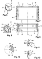
figures 5 et6 sont des vues en perspective du capuchon et de l'insert du dispositif de lafigure 1 ; - la
figure 7 est une vue en coupe axiale de l'insert de lafigure 6 ; - les
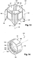
figures 8 et 9 sont des vues analogues auxfigures 6 à 7 montrant la bague du dispositif de lafigure 1 ; - la
figure 10 est une vue à plus grande échelle du détail F de la bague de lafigure 9 ; - les
figures 11 et 12 sont des vues en section illustrant le raclage de l'orifice par le relief dans le dispositif de lafigure 1 au cours de la mise en place du capot sur le récipient ; et - les
figures 13 et 14 sont des vues analogues auxfigures 6 et 8 illustrant une variante de réalisation du dispositif de l'invention. - On a illustré sur les figures un article 2 comprenant un dispositif 4 renfermant un produit cosmétique 6.
- Ce dernier peut être un produit de soin et/ou de maquillage pour le visage ou le corps ou encore un produit pharmaceutique tel qu'un médicament. Il s'agit d'un produit liquide ou pâteux et distribué à l'utilisateur sous cette forme par l'article. Ce produit pourra être formé par une solution aqueuse, une solution grasse ou encore une émulsion.
- L'article 2 comprend un corps constituant ici un flacon qui renferme un réservoir 8 du produit 6. Ce réservoir est surmonté par un mécanisme 10 de distribution du produit à travers une buse 14 s'étendant à l'extrémité supérieure du corps. La buse présente un orifice 16 de distribution du produit. En l'espèce, le mécanisme 10 de distribution du produit à travers l'orifice comprend une pompe apte à extraire du produit du réservoir et à l'acheminer jusqu'à l'orifice 16. Cette pompe est d'un type connu en lui-même et ne sera pas décrite en détail ici. La buse 14 est solidaire d'un bouton-poussoir 18 qui est monté mobile à coulissement par rapport au corps suivant un axe principal vertical 22 de l'article 2. L'article est agencé de sorte que, lorsque l'utilisateur exerce une pression sur la face supérieure 20 du bouton formant le sommet du corps, cette pression provoque la descente du bouton 18 à l'intérieur du corps et dans le même temps l'administration d'une dose de produit au moyen de la pompe à travers l'orifice 16. Le détail du circuit mettant en communication le réservoir 8, la pompe 10 et l'orifice est d'un type classique et n'a pas été illustré.
- Le bouton-poussoir 18 a ici une forme générale à symétrie de révolution autour de l'axe 22. Il présente notamment une face latérale cylindrique 24 à section circulaire dans un plan perpendiculaire à l'axe 22. La buse s'étend en saillie de cette face sur un côté du bouton, l'orifice étant ménagé à l'extrémité libre de la buse, formée par une face généralement cylindrique d'axe 22. On prévoit ici que le bouton-poussoir 18 est mobile à rotation autour de l'axe 22 par rapport au réservoir sans que cette caractéristique soit néanmoins une obligation.
- L'article 2 comporte un capot 26 comprenant un capuchon 28, un insert 30 et une bague 32 illustrés respectivement aux
figures 5 ,6 et 8 et formant des pièces distinctes rigidement fixées les unes aux autres. L'insert et la bague s'étendent à l'intérieur du capuchon. Seul le capuchon 28 est visible lorsqu'on observe le capot depuis l'extérieur, comme illustré à lafigure 5 . Il s'agit ici d'un capot qui n'est pas fixé à demeure au récipient en étant monté mobile sur ce dernier. Ainsi, pour obtenir du produit, on sépare totalement le capot du récipient. - Le capuchon présente en l'espèce une paroi latérale ou jupe 34 de forme cylindrique à section généralement carrée dans un plan perpendiculaire à l'axe 22. Cette jupe est obturée à son extrémité supérieure par une paroi plane 36. Le capuchon est par exemple réalisé dans un matériau relativement dur tel qu'un métal ou un matériau thermoplastique.
- En référence aux
figures 6 et 7 , l'insert 30 comprend une paroi latérale ou jupe 40 elle aussi de forme générale cylindrique d'axe 22 à section généralement carrée dans un plan perpendiculaire à cet axe. Toutefois, la forme de cette paroi n'est pas rigoureusement cylindrique car l'insert 30 présente une dimension transversale à l'axe 22 qui va en diminuant à mesure qu'on se rapproche du sommet de l'insert. Près de ce sommet, l'insert comprend une paroi plane d'extrémité 42 s'étendant dans un plan perpendiculaire à l'axe 22. La face supérieure 44 de cette paroi s'étend à distance du bord d'extrémité supérieure 46 de la paroi 40. La paroi 42 est ainsi légèrement en retrait de ce bord. La paroi 42 présente un large orifice circulaire 47 occupant la plus grande partie de l'emplacement de cette paroi. L'insert est réalisé dans une matière relativement dure, par exemple un matériau thermoplastique. - En référence aux
figures 8 et 9 , la bague 32 comprend une paroi latérale ou jupe 50 qui présente une face externe 51 de forme générale tronconique d'axe 22 dont la section va en diminuant à mesure qu'on se rapproche de l'extrémité supérieure de la bague. Cette extrémité est formée par une paroi d'extrémité 52 qui obture la jupe 50 à son bord supérieur en dépassant radialement de ce bord de sorte que la paroi 52 ménage un rebord circonférentiel 54 en saillie radiale de la jupe 50 au niveau de cette extrémité. La paroi 52 a, en plan, une forme générale carrée de sorte qu'elle présente quatre coins 72. Mise à part la paroi 52, la bague 32 a une forme générale à symétrie de révolution autour de l'axe 22. - La différence de forme entre les parois 40 et 50 est notamment visible sur les
figures 1 et 2 sachant que, dans cette dernière, la buse a été tournée de 45° par rapport au réservoir et par rapport à sa position sur lafigure 1 . Sur lafigure 1 , elle était dirigée suivant une diagonale du carré de la paroi 36 alors que sur lafigure 2 elle s'étend suivant une médiane de cette paroi. - Tandis que la face externe 51 de la jupe 50 a une forme tronconique, sa face interne 56 présente, sur un tronçon supérieur contiguë à la paroi d'extrémité 52, une forme cylindrique d'axe 22 à section circulaire dans un plan perpendiculaire à cet axe.
- Au-dessous de ce tronçon, la face interne présente successivement, à partir de ce tronçon et jusqu'au bord d'extrémité inférieure 58 de la jupe 50, une cavité supérieure 60, une lèvre supérieure 62, une cavité inférieure 64 et une lèvre inférieure 66, ces cavités et reliefs se succédant dans cet ordre en étant contiguës. Les lèvres 62, 66 ainsi que les cavités 60, 64 ont chacune une forme annulaire, les cavités définissant des gorges parallèles.
- La cavité 60 s'étend en retrait du tronçon cylindrique de la face 56 suivant la direction radiale à l'axe 22, c'est-à-dire à plus grande distance de l'axe que ce tronçon.
- La lèvre supérieure 62 s'étend en revanche en saillie du tronçon cylindrique de la face 56, et par conséquent de la cavité supérieure 60, suivant la direction radiale. Comme illustré à plus grande échelle à la
figure 10 , la lèvre est délimitée par deux faces principales, à savoir une face supérieure 68 de forme tronconique avec la section du cône la plus étroite dirigée vers le bas et une face inférieure 70 de forme plane et perpendiculaire à l'axe 22. - La cavité inférieure 64 s'étend, tout comme la cavité 60, en retrait du tronçon 56 suivant la direction radiale mais encore plus en retrait que ce dernier. La hauteur de cette cavité mesurée parallèlement à l'axe 22 est également supérieure à la hauteur de la cavité 60 et même en l'espèce égale au double de cette hauteur.
- La lèvre inférieure 66 s'étend en retrait du tronçon 56 et donc de la lèvre 62, ainsi que de la cavité supérieure 60 suivant la direction radiale. Elle s'étend toutefois en saillie de la cavité inférieure 64 qui lui est contiguë. Elle présente une forme analogue à celle de la lèvre supérieure 62.
- La face externe 51 de la bague présente un relief annulaire 72 illustré notamment à la
figure 4 à profil en arc de cercle et s'étendant en saillie de cette paroi. - La bague 32 est ici réalisée dans un matériau relativement mou, c'est-à-dire plus mou ou encore moins dur que celui de l'insert 30 et du capuchon 28. Il s'agit par exemple d'un élastomère organique ou minéral tel que du silicone en l'espèce. On pourrait sinon utiliser un élastomère thermoplastique.
- Comme on le voit notamment sur les
figures 2 et 3 , la bague 32 est reçue dans le capuchon 28 dans une position telle que sa paroi supérieure 52 est en butée contre la paroi supérieure 36 du capuchon en réalisant un contact surfacique avec cette dernière. L'insert 30 est interposé radialement au niveau de son tronçon supérieur entre, d'une part, le capuchon extérieurement et, d'autre part, la bague intérieurement. La jupe 50 de la bague, qui forme ce qu'on peut appeler une chaussette, traverse l'orifice 47 de l'insert de sorte que la paroi 42 de ce dernier vient en appui par sa face supérieure 44 suivant la direction de l'axe 22 contre le rebord 54 de la bague afin de maintenir la paroi 52 en appui contre le sommet 36 du capuchon. En vue de ce maintien, le bord 46 de l'insert s'étend à une distance d, non nulle, de la paroi 36. Le rebord 54 de la bague présente une épaisseur f plus grande que la distance séparant la face 44 et l'extrémité 46, égale à la différence f-d. - Comme illustré à la
figure 3 , le relief 72 de la chaussette s'étend contre la paroi 42 de l'insert suivant la direction axiale afin de réduire les risques de séparation de l'insert et de la bague suivant la direction axiale. - En référence à la
figure 4 , le capuchon 28 présente un relief similaire 76 de forme annulaire et s'étendant radialement en saillie de la face interne du capuchon. Ce relief vient en appui contre le bord d'extrémité de la jupe 40 de l'insert afin d'empêcher le coulissement de ce dernier par rapport au capuchon suivant la direction de l'axe 22. - Comme on le voit notamment sur les
figures 2 et 3 , la lèvre supérieure 62 est séparée de l'axe 22 par une distance plus courte que la distance de l'orifice 16 à ce même axe. La lèvre vient donc en interférence avec l'orifice, comme illustré auxfigures 11 et 12 , lorsque le capot franchit la buse, soit lorsqu'on place le capot sur le récipient, soit lorsqu'on l'en enlève. - La face cylindrique 56 de la chaussette s'étend à une distance de l'axe 22 sensiblement égale à celle séparant l'orifice 16 de ce même axe et de préférence légèrement inférieure à cette distance. Ainsi, lorsque le capot est dans la position illustrée à la
figure 2 dans laquelle il ferme le récipient, le tronçon cylindrique est en contact avec la buse 14 dont il obture l'orifice 16 en réalisant un contact surface contre surface avec ce dernier. La chaussette étant réalisée en un matériau relativement mou, elle forme à cet endroit un obturateur qui obture l'orifice de façon efficace, même si la forme de ce dernier ne correspond pas au repos à celle de la chaussette. - Nous allons maintenant présenter le fonctionnement du dispositif. On suppose que l'utilisateur a distribué une dose de produit 6 à travers l'orifice 16 en actionnant le bouton-poussoir 18. Lorsqu'il vient replacer le capot 26 sur le récipient, la lèvre supérieure 62 vient, comme illustré à la
figure 11 , en appui sur l'extrémité de la face supérieure de la buse, ce qui provoque la déformation et l'écrasement de cette lèvre contre le tronçon cylindrique 56 par déformation de la cavité supérieure 60. Au cours de la suite du mouvement, la lèvre 62 ainsi déformée parcourt l'orifice 16 en le raclant ou en l'essuyant, et en élimine ainsi le produit excédentaire qui pouvait s'y trouver. Ce produit est amené dans la cavité inférieure 64 lorsque la lèvre revient en position de repos. Lafigure 11 illustre la position de la lèvre sur la buse au début de ce mouvement de raclage et lafigure 12 illustre les mêmes éléments à la fin du mouvement de raclage. Lorsque la lèvre a franchi la buse, elle reprend par élasticité sa forme d'origine, tandis que la buse vient en contact avec le tronçon cylindrique de la face 56 et que son orifice se trouve ainsi obturé de façon étanche par la bague. Cette configuration demeure tant que le capot occupe la position illustrée à lafigure 2 , dans laquelle il ferme le récipient. Ainsi, au cours du mouvement, la lèvre est tout d'abord venue racler et essuyer l'orifice de la buse pour en éliminer le produit excédentaire, puis après passage de l'orifice devant la cavité supérieure 60, le capot est venu obturer l'orifice de façon étanche grâce au caractère relativement mou du matériau de la chaussette. - En l'espèce, comme illustré à la
figure 1 , le dispositif 4 porte des reliefs 76 et le capot présente des cavités complémentaires 78 formant des moyens de clipsage du capot sur le dispositif afin d'immobiliser le capot sur le corps quand il ferme le récipient. - Ensuite, lorsque l'utilisateur ôte le capot du récipient, la lèvre supérieure 62 vient à nouveau racler l'orifice 16 en se déformant cette fois vers le bas et en écrasant la cavité inférieure 64. Une fois le capot ôté du récipient, l'utilisateur a sous les yeux une buse présentant un orifice 16 parfaitement propre.
- On observera que les opérations de raclage ou d'essuyage ne nécessitent pas de déformer le capuchon 28 qui est d'ailleurs essentiellement rigide. L'invention ne modifie pas la gestuelle de l'utilisateur et ne nécessite aucune action particulière de sa part. C'est en effet au cours du mouvement pour replacer le capot sur le récipient qu'a lieu le nettoyage de l'orifice, puis son obturation. Ces actions se produisent sans que l'utilisateur en ait conscience. D'ailleurs, la lèvre supérieure 62 se trouve à grande distance du bord inférieur du capot. Elle est logée dans la moitié supérieure de ce dernier et demeure largement invisible en utilisation normale sauf à regarder spécifiquement dans le capot.
- On voit que le relief 62 est séparé du bord libre d'extrémité inférieure du capot par la portion inférieure de la face interne du capuchon 28, la portion inférieure de la face interne de l'insert et la lèvre inférieure 66 et la cavité 64 de la bague. Il s'étend en saillie radiale de tous ces éléments.
- L'invention n'engendre aucune contrainte spécifique sur la forme et les matériaux utilisés pour réaliser l'article et, en particulier, le récipient. On peut notamment donner au choix une forme circulaire ou carrée ou tout autre forme, dans un plan perpendiculaire à l'axe 22, à la jupe 34 conférant son aspect extérieur au capot.
- De même, l'invention ne nécessite pas de placer le capot sur le récipient dans une position angulaire particulière autour de l'axe 22. On voit au contraire que, grâce à la symétrie de révolution de la bague, toute position du capot sur le récipient permet d'obtenir les effets précités.
- Pour réaliser le capot, on monte tout d'abord la bague 32 dans l'insert 30. Pour cela, on introduit l'extrémité inférieure de la bague dans l'orifice 47 de l'insert jusqu'à mettre le rebord 54 de la bague en appui suivant la direction de l'axe 22 contre la paroi 42 qui a quand à elle franchi le relief 72. On introduit ensuite l'ensemble ainsi constitué à l'intérieur du capuchon jusqu'à mettre la paroi 52 en appui contre le sommet du capuchon et à franchir avec l'insert le relief 76. Ces assemblages peuvent être effectués à force afin d'obtenir un ajustement serré des trois pièces entre elles ne nécessitant pas de collage.
- La réalisation de la bague dans un matériau tel qu'un l'élastomère facilite la fabrication de celle-ci par moulage. En effet, le caractère mou et déformable conféré à cette pièce par le matériau permet de la démouler facilement même si elle présente des formes en contre-dépouille. De plus, grâce à ce matériau relativement mou, on peut librement choisir la forme de la face de la buse portant l'orifice, le matériau de la bague s'adaptant dans tous les cas à la forme choisie. La relative dureté du matériau utilisé pour constituer l'insert 30 favorise la fixation robuste de la bague à l'intérieur du capuchon 28.
- Nous allons maintenant décrire une variante de réalisation du dispositif de l'invention.
- Le dispositif comporte, comme précédemment, un flacon muni d'un capot qui ont chacun dans un plan perpendiculaire à l'axe principal vertical 22 une section de profil globalement carré. On peut prévoir que les quatre faces du flacon et que les quatre faces du capot sont bombées.
- Comme précédemment, la buse est solidaire d'un bouton-poussoir qui est monté mobile à coulissement par rapport au corps suivant l'axe 22. Dans cette variante, contrairement au dispositif précédent, le bouton-poussoir n'est pas mobile à rotation autour de l'axe 22 par rapport au réservoir. La buse du bouton-poussoir occupe une position fixe autour de l'axe principal en étant dirigée perpendiculairement à l'une des quatre faces du flacon. L'extrémité libre de la buse s'étend suivant une direction rectiligne perpendiculaire à l'axe principal 22. L'orifice de distribution de la buse s'étend donc dans un plan parallèle à l'une des faces du flacon.
- Comme précédemment, le capot comprend un capuchon dans lequel sont logés un insert 130 et une bague 132 illustrés sur les figures. De nouveau, l'insert est réalisé dans un matériau relativement rigide tandis que la bague est en matière souple.
- L'orifice 47 de l'insert est défini, comme précédemment, par une face cylindrique 180 ayant pour axe l'axe 22 et dont la section, dans un plan perpendiculaire à cet axe, est circulaire. Il s'agit de la face interne supérieure de l'insert.
- L'insert 130 présente ici une face interne inférieure 182 de forme tronconique coaxiale à l'axe 22. Le bord supérieur de cette face a une forme circulaire. Il correspond à la section de plus petit diamètre de la face. Au niveau de ce bord, la face tronconique 182 est séparée de la face cylindrique 180 par une marche 184 qui forme un épaulement disposé de sorte que la face tronconique 182 s'étend à cet endroit en saillie radiale de la face cylindrique 180 par référence à l'axe 22. Les faces externes de l'insert occupant de façon générale un parallélépipède rectangle, l'intersection de ces faces avec la face tronconique 182 est formée par quatre arches 186 en forme d'hyperbole. Ces arches forment le bord inférieur de la face interne inférieure 182. Les intersections de ces arches entre elles forment des pointes 187 qui sont en coïncidence avec les angles ou les coins du capot.
- La section de la face tronconique 182 va donc en se rétrécissant de bas en haut. Elle forme une face de centrage et de guidage lorsqu'on replace le capot sur le flacon par dessus le bouton-poussoir. Cette face guide ce dernier en appui vers le centre du capot.
- De plus, la marche 184 évite que la buse accroche le bord inférieur de la bague lorsqu'on ferme le flacon avec le capot.
- Comme précédemment, la bague 132 présente une lèvre 62 qui parcourt l'orifice de la buse en le raclant ou en l'essuyant lors de la fermeture.
- Le dispositif comprend en outre des moyens pour réaliser une indexation angulaire de la bague 132 par rapport à l'insert 130 autour de l'axe 22 au moment de leur montage l'un dans l'autre. Il s'agit en l'espèce de moyens qui agissent par complémentarité de forme. La bague 132 présente ainsi une ou plusieurs rainures 196 s'étendant en saillie radiale de la face externe 51 de la jupe. Cette face a, en l'espèce, une forme cylindrique à section circulaire dans un plan perpendiculaire à l'axe 22. Chaque rainure a une forme rectiligne parallèle à l'axe 22. En l'espèce, les rainures sont au nombre de deux et diamétralement opposées de part et d'autre de l'axe. L'insert 130 présente dans sa face supérieure interne 180 des nervures 198 ayant une forme et une disposition homologue de celle des rainures 196 afin d'accueillir celles-ci lorsque la bague est montée dans l'insert.
- En l'espèce, le tronçon supérieur 156 de la face interne de la jupe 50 présente quatre méplats 192 régulièrement répartis autour de l'axe 22 de sorte que les centres de deux méplats successifs sont séparés par un angle de 90 ° autour de cet axe. Les méplats en regard sont parallèles deux à deux tandis que les méplats successifs sont perpendiculaires l'un à l'autre, chaque méplat s'étendant dans un plan parallèle à l'axe 22 dont la normale coupe cet axe. La jonction entre les bords des méplats successifs en direction circonférentielle s'effectue au moyen de quatre facettes 194 de forme cylindrique ayant un profil en arc de cercle dans un plan perpendiculaire à l'axe 22.
- Les quatre méplats 192 sont en coïncidence autour de l'axe 22 avec les quatre faces externes du capot, chaque méplat étant parallèle à l'une des faces. Ces méplats augmentent localement l'épaisseur de la chaussette et surtout offrent à la buse une surface de contact plane qui est rectiligne dans deux directions respectivement parallèle et orthogonale à l'axe 22 et rectiligne dans un plan radial à cet axe. Cette surface est donc parallèle au plan de l'extrémité libre de la buse.
- Le dispositif est agencé de sorte que le capot peut seulement occuper quatre positions différentes par rapport au flacon et que, dans chacune de celles-ci, les faces du flacon et du capot sont en coïncidence. La buse s'étendant suivant une direction perpendiculaire à l'une des faces principales du flacon, la buse est à chaque fois perpendiculaire à l'un des méplats 192 avec lequel elle vient en contact. Les méplats assurent donc l'obturation de l'orifice de distribution de la buse quelle que soit la position du capot sur le flacon.
- Bien entendu, on pourra apporter à l'invention de nombreuses modifications sans sortir du cadre de celle-ci.
- On pourra donner au récipient des formes variées. Bien qu'il soit avantageux de donner à certaines des pièces une forme à symétrie de révolution, cela n'est pas une nécessité dans le cadre de l'invention.
- La pompe est facultative. Le dispositif pourra comprendre par exemple un tube que l'on presse ou que l'on écrase pour en faire sortir le produit. Il peut s'agir d'un pot muni d'un piston mobile.
- On pourra prévoir de visser le capot sur le corps.
- Le capot pourra être formé d'une unique pièce incorporant le capuchon, l'insert et la bague, en étant fabriqué par bi-injection de matériaux. On peut même prévoir un capot d'une seule pièce et monobloc, par exemple intégralement en élastomère.
Claims (10)
- Dispositif (4) de produit cosmétique qui comprend :- un récipient présentant une buse (14) ayant un orifice (16) de distribution de produit ménagé à l'extrémité libre de la buse ; et- un capot (26) présentant un relief interne (62) agencé de façon à parcourir l'orifice lorsqu'on vient fermer le récipient avec le capot, le capot (26) étant agencé de sorte que, lorsqu'il ferme le récipient, il est en appui contre l'orifice (16) et l'obture, la buse s'étendant en saillie sur un côté caractérisé en ce que le relief (62) est agencé de façon à s'étendre tout entier à distance de l'orifice lorsque le capot ferme le récipient, le relief formant par exemple une lèvre.
- Dispositif selon la revendication précédente dans lequel le capot (26) est agencé pour obturer l'orifice (16) au moyen d'un obturateur en matière souple.
- Dispositif selon l'une quelconque des revendications précédentes dans lequel le relief (62) s'étend à distance d'un bord d'extrémité libre du capot.
- Dispositif selon l'une quelconque des revendications précédentes dans lequel le relief (62) présente une symétrie de révolution autour d'un axe (22) du capot (26).
- Dispositif selon l'une quelconque des revendications précédentes dans lequel le capot (26) présente au moins une cavité (60, 64) contiguë au relief (62), les cavités étant par exemple au nombre de deux et s'étendant de préférence respectivement au-dessus et au-dessous du relief (62).
- Dispositif selon l'une quelconque des revendications précédentes dans lequel le capot (26) comprend un capuchon externe (28) et un élément interne (32) entièrement logé dans le capuchon et portant le relief (62), le capuchon et l'élément formant des pièces distinctes.
- Dispositif selon la revendication précédente dans lequel l'élément interne (32) est réalisé dans un matériau moins dur qu'un matériau du capuchon (28), l'élément interne étant réalisé par exemple en élastomère.
- Dispositif selon l'une quelconque des revendications 6 à 7 dans lequel le capot (26) comprend un insert (30) formant une pièce distincte du capuchon (28) et de l'élément interne (32) et assurant le maintien de l'élément interne dans le capuchon.
- Dispositif selon l'une quelconque des revendications précédentes qui comprend un produit cosmétique (6) liquide ou pâteux.
- Procédé de fabrication d'un capot (26) d'un dispositif selon l'une quelconque des revendications précédentes, caractérisé en ce qu'on assemble un insert (30) et un élément interne (32) portant un relief (62) tel qu'une lèvre, puis on introduit l'assemblage dans un capuchon (28) pour former le capot de sorte que le relief (62) forme un relief interne du capot.
Applications Claiming Priority (2)
| Application Number | Priority Date | Filing Date | Title |
|---|---|---|---|
| FR0955578A FR2948861B1 (fr) | 2009-08-07 | 2009-08-07 | Dispositif de produit cosmetique presentant un orifice de distribution |
| PCT/FR2010/051634 WO2011015777A2 (fr) | 2009-08-07 | 2010-07-30 | Dispositif de produit cosmetique presentant un orifice de distribution |
Publications (2)
| Publication Number | Publication Date |
|---|---|
| EP2461716A2 EP2461716A2 (fr) | 2012-06-13 |
| EP2461716B1 true EP2461716B1 (fr) | 2018-10-24 |
Family
ID=42139031
Family Applications (1)
| Application Number | Title | Priority Date | Filing Date |
|---|---|---|---|
| EP10762961.0A Not-in-force EP2461716B1 (fr) | 2009-08-07 | 2010-07-30 | Dispositif de produit cosmetique presentant un orifice de distribution |
Country Status (7)
| Country | Link |
|---|---|
| US (1) | US8590748B2 (fr) |
| EP (1) | EP2461716B1 (fr) |
| JP (1) | JP5797196B2 (fr) |
| KR (1) | KR101749170B1 (fr) |
| CN (1) | CN102686126B (fr) |
| FR (1) | FR2948861B1 (fr) |
| WO (1) | WO2011015777A2 (fr) |
Families Citing this family (4)
| Publication number | Priority date | Publication date | Assignee | Title |
|---|---|---|---|---|
| BR112019002314A2 (pt) * | 2016-08-05 | 2019-06-18 | Unilever Nv | produto de vaporização de roupa e método de produção de um spray de vaporização de roupa |
| JP6715140B2 (ja) * | 2016-09-13 | 2020-07-01 | 株式会社マンダム | 噴射容器、キャップ部材及び噴射製品 |
| WO2018132540A1 (fr) * | 2017-01-12 | 2018-07-19 | Becton Dickinson and Company Limited | Membrane résistante à la contrainte de système fermé |
| US11186413B1 (en) * | 2020-06-01 | 2021-11-30 | UmaCor Design LLC | Dripless cap and cup |
Citations (2)
| Publication number | Priority date | Publication date | Assignee | Title |
|---|---|---|---|---|
| EP0461894A2 (fr) * | 1990-06-15 | 1991-12-18 | Calmar, Inc. | Capuchon de protection et dispositif d'essuyage pour orifice de décharge de distributeur |
| US20040050871A1 (en) * | 2002-06-28 | 2004-03-18 | L'oreal | Assembly for packaging and distribution of a product |
Family Cites Families (20)
| Publication number | Priority date | Publication date | Assignee | Title |
|---|---|---|---|---|
| US3655100A (en) * | 1970-03-13 | 1972-04-11 | Isral J Markowitz | Safety cover cap for an aerosol container |
| US3809300A (en) * | 1971-06-03 | 1974-05-07 | T Russell | Closure device for dispensing tubes |
| FR2605983B1 (fr) * | 1986-11-03 | 1988-12-02 | Cebal | Distributeur pour produit pateux et procede d'introduction de son piston a l'interieur de son corps tubulaire |
| FR2609967B1 (fr) | 1987-01-23 | 1989-08-04 | Cebal | Distributeur pour produit pateux a poussoir axial rotatif |
| US5094364A (en) * | 1990-06-15 | 1992-03-10 | Calmar Inc. | Protective overcap and wiper for dispenser discharge orifice |
| US5207785A (en) * | 1991-08-19 | 1993-05-04 | Calmar Inc. | Protector cap and wiper for dispenser discharge orifice |
| US5449094A (en) * | 1992-05-18 | 1995-09-12 | Sofab | Dispenser with plunging sleeve |
| GB9507185D0 (en) * | 1995-04-06 | 1995-05-31 | Incro Ltd | Spraying apparatus and nozzle devices |
| AU2421197A (en) * | 1996-03-25 | 1997-10-17 | Charles Chang | Liquid dispenser for products utilizing a brush-type applicator |
| JPH10337509A (ja) * | 1997-06-06 | 1998-12-22 | Shiseido Co Ltd | ディスペンサーのキャップ及びディスペンサー |
| FR2786075B1 (fr) | 1998-11-24 | 2001-02-02 | Coty Sa | Conditionnement etanche pour compositions cosmetiques et/ou pharmaceutiques |
| ES2247246T3 (es) * | 1998-11-24 | 2006-03-01 | Coty Sa | Envase y tapa para envasar composiciones cosmeticas o farmaceuticas. |
| FR2796921B1 (fr) * | 1999-07-28 | 2001-10-05 | Valois Sa | Dispositif de distribution de produit fluide avec systeme d'obturation |
| FR2866819B1 (fr) * | 2004-02-26 | 2006-03-31 | Techpack Int | Distributeur-applicateur typiquement a tete massante |
| FR2870215B1 (fr) * | 2004-05-17 | 2007-08-10 | Valois Sas | Capot pour tete de distribution de produit fluide. |
| US7510102B2 (en) * | 2006-02-22 | 2009-03-31 | Schmitt William H | Clog resistant actuator and overcap |
| KR200417222Y1 (ko) * | 2006-03-09 | 2006-05-25 | 김승섭 | 위조방지용 안전 캡 |
| US20070289603A1 (en) * | 2006-06-15 | 2007-12-20 | Hct Asia Ltd. | Cosmetics Dispenser with Automatic Closure |
| US20090008413A1 (en) * | 2007-04-17 | 2009-01-08 | Choi Hee Jin | Airless dispensing pump container with an airtight push down type nozzle head |
| CN107346765B (zh) * | 2016-05-04 | 2019-11-26 | 通用电气公司 | 桥臂电路封装组件及全桥电路封装组件 |
-
2009
- 2009-08-07 FR FR0955578A patent/FR2948861B1/fr not_active Expired - Fee Related
-
2010
- 2010-07-30 US US13/389,086 patent/US8590748B2/en not_active Expired - Fee Related
- 2010-07-30 WO PCT/FR2010/051634 patent/WO2011015777A2/fr active Application Filing
- 2010-07-30 KR KR1020127006107A patent/KR101749170B1/ko active IP Right Grant
- 2010-07-30 CN CN201080045214.0A patent/CN102686126B/zh not_active Expired - Fee Related
- 2010-07-30 JP JP2012523365A patent/JP5797196B2/ja not_active Expired - Fee Related
- 2010-07-30 EP EP10762961.0A patent/EP2461716B1/fr not_active Not-in-force
Patent Citations (2)
| Publication number | Priority date | Publication date | Assignee | Title |
|---|---|---|---|---|
| EP0461894A2 (fr) * | 1990-06-15 | 1991-12-18 | Calmar, Inc. | Capuchon de protection et dispositif d'essuyage pour orifice de décharge de distributeur |
| US20040050871A1 (en) * | 2002-06-28 | 2004-03-18 | L'oreal | Assembly for packaging and distribution of a product |
Also Published As
| Publication number | Publication date |
|---|---|
| FR2948861A1 (fr) | 2011-02-11 |
| WO2011015777A3 (fr) | 2011-04-28 |
| KR20120051736A (ko) | 2012-05-22 |
| FR2948861B1 (fr) | 2013-08-30 |
| JP5797196B2 (ja) | 2015-10-21 |
| KR101749170B1 (ko) | 2017-06-20 |
| WO2011015777A2 (fr) | 2011-02-10 |
| US20120187149A1 (en) | 2012-07-26 |
| CN102686126B (zh) | 2015-08-12 |
| EP2461716A2 (fr) | 2012-06-13 |
| CN102686126A (zh) | 2012-09-19 |
| US8590748B2 (en) | 2013-11-26 |
| JP2013500912A (ja) | 2013-01-10 |
Similar Documents
| Publication | Publication Date | Title |
|---|---|---|
| EP2091836B1 (fr) | Distributeur de produit fluide | |
| EP2103542B1 (fr) | Dispositif de protection pour système de conditionnement d'un produit, notamment d'un produit cosmétique | |
| EP2739182B1 (fr) | Distributeur de produit fluide | |
| EP3094419B1 (fr) | Reservoir de produit fluide et distributeur | |
| EP2903907B1 (fr) | Dispositif d'emballage et son procede d'assemblage | |
| EP0929473B1 (fr) | Dispositif d'obturation de l'orifice de distribution d'un distributeur de produits fluides | |
| EP2461716B1 (fr) | Dispositif de produit cosmetique presentant un orifice de distribution | |
| EP3603817B1 (fr) | Montage et démontage facilité d'une pompe par rapport au réservoir | |
| EP2442914B1 (fr) | Distributeur de produit fluide | |
| WO2015155472A1 (fr) | Flacon | |
| EP0329582B1 (fr) | Distributeur pour produit pâteux comprenant un poussoir axial à distribution latérale et un élément de masquage de son orifice de sortie | |
| FR2954754A1 (fr) | Capsule distributrice pour flacon de produit de consistance liquide ou visqueuse et flacon muni d'une telle capsule | |
| EP1651540A1 (fr) | Tete de distribution de produit fluide | |
| EP2178415A2 (fr) | Dispositif de produit cosmetique comprenant un reservoir et un applicateur | |
| EP0277893A1 (fr) | Distributeur pour produit pateux à poussoir axial rotatif | |
| EP3181474B1 (fr) | Bouchon en plastique stop-goutte, notamment pour liquide plus ou moins visqueux | |
| FR3095133A1 (fr) | Distributeur de produit fluide | |
| EP3756769B1 (fr) | Système de fixation d'un organe de distribution sur un col fileté d'un réservoir | |
| WO2024022604A1 (fr) | Distributeur d'un produit fluide, recharge associée et réceptacle associé | |
| WO2024022605A1 (fr) | Recharge pour réceptacle de produit fluide et réceptacle associé | |
| FR2769005A1 (fr) | Capsule service pour recipient distributeur | |
| FR3102759A1 (fr) | Capsule avec valve intégrée pour récipient de stockage de produit, notamment d’un produit cosmétique | |
| FR3067014A1 (fr) | Assemblage d'un dispositif de distribution pour flacon | |
| FR2878698A1 (fr) | Distributeur d'un produit solide ou pateux | |
| EP3010849A1 (fr) | Tete et procede de montage d'un organe de distribution sur un col de reservoir |
Legal Events
| Date | Code | Title | Description |
|---|---|---|---|
| PUAI | Public reference made under article 153(3) epc to a published international application that has entered the european phase |
Free format text: ORIGINAL CODE: 0009012 |
|
| 17P | Request for examination filed |
Effective date: 20120227 |
|
| AK | Designated contracting states |
Kind code of ref document: A2 Designated state(s): AL AT BE BG CH CY CZ DE DK EE ES FI FR GB GR HR HU IE IS IT LI LT LU LV MC MK MT NL NO PL PT RO SE SI SK SM TR |
|
| RIN1 | Information on inventor provided before grant (corrected) |
Inventor name: MATHIEU, NICOLAS Inventor name: POUCHAIN, JEAN-EUDES |
|
| DAX | Request for extension of the european patent (deleted) | ||
| STAA | Information on the status of an ep patent application or granted ep patent |
Free format text: STATUS: EXAMINATION IS IN PROGRESS |
|
| 17Q | First examination report despatched |
Effective date: 20170522 |
|
| GRAP | Despatch of communication of intention to grant a patent |
Free format text: ORIGINAL CODE: EPIDOSNIGR1 |
|
| STAA | Information on the status of an ep patent application or granted ep patent |
Free format text: STATUS: GRANT OF PATENT IS INTENDED |
|
| INTG | Intention to grant announced |
Effective date: 20180511 |
|
| GRAS | Grant fee paid |
Free format text: ORIGINAL CODE: EPIDOSNIGR3 |
|
| GRAA | (expected) grant |
Free format text: ORIGINAL CODE: 0009210 |
|
| STAA | Information on the status of an ep patent application or granted ep patent |
Free format text: STATUS: THE PATENT HAS BEEN GRANTED |
|
| AK | Designated contracting states |
Kind code of ref document: B1 Designated state(s): AL AT BE BG CH CY CZ DE DK EE ES FI FR GB GR HR HU IE IS IT LI LT LU LV MC MK MT NL NO PL PT RO SE SI SK SM TR |
|
| REG | Reference to a national code |
Ref country code: GB Ref legal event code: FG4D Free format text: NOT ENGLISH |
|
| REG | Reference to a national code |
Ref country code: CH Ref legal event code: EP |
|
| REG | Reference to a national code |
Ref country code: IE Ref legal event code: FG4D Free format text: LANGUAGE OF EP DOCUMENT: FRENCH |
|
| REG | Reference to a national code |
Ref country code: AT Ref legal event code: REF Ref document number: 1055647 Country of ref document: AT Kind code of ref document: T Effective date: 20181115 |
|
| REG | Reference to a national code |
Ref country code: DE Ref legal event code: R096 Ref document number: 602010054601 Country of ref document: DE |
|
| REG | Reference to a national code |
Ref country code: NL Ref legal event code: MP Effective date: 20181024 |
|
| REG | Reference to a national code |
Ref country code: LT Ref legal event code: MG4D |
|
| REG | Reference to a national code |
Ref country code: AT Ref legal event code: MK05 Ref document number: 1055647 Country of ref document: AT Kind code of ref document: T Effective date: 20181024 |
|
| PG25 | Lapsed in a contracting state [announced via postgrant information from national office to epo] |
Ref country code: NL Free format text: LAPSE BECAUSE OF FAILURE TO SUBMIT A TRANSLATION OF THE DESCRIPTION OR TO PAY THE FEE WITHIN THE PRESCRIBED TIME-LIMIT Effective date: 20181024 |
|
| PG25 | Lapsed in a contracting state [announced via postgrant information from national office to epo] |
Ref country code: IS Free format text: LAPSE BECAUSE OF FAILURE TO SUBMIT A TRANSLATION OF THE DESCRIPTION OR TO PAY THE FEE WITHIN THE PRESCRIBED TIME-LIMIT Effective date: 20190224 Ref country code: FI Free format text: LAPSE BECAUSE OF FAILURE TO SUBMIT A TRANSLATION OF THE DESCRIPTION OR TO PAY THE FEE WITHIN THE PRESCRIBED TIME-LIMIT Effective date: 20181024 Ref country code: LT Free format text: LAPSE BECAUSE OF FAILURE TO SUBMIT A TRANSLATION OF THE DESCRIPTION OR TO PAY THE FEE WITHIN THE PRESCRIBED TIME-LIMIT Effective date: 20181024 Ref country code: HR Free format text: LAPSE BECAUSE OF FAILURE TO SUBMIT A TRANSLATION OF THE DESCRIPTION OR TO PAY THE FEE WITHIN THE PRESCRIBED TIME-LIMIT Effective date: 20181024 Ref country code: PL Free format text: LAPSE BECAUSE OF FAILURE TO SUBMIT A TRANSLATION OF THE DESCRIPTION OR TO PAY THE FEE WITHIN THE PRESCRIBED TIME-LIMIT Effective date: 20181024 Ref country code: BG Free format text: LAPSE BECAUSE OF FAILURE TO SUBMIT A TRANSLATION OF THE DESCRIPTION OR TO PAY THE FEE WITHIN THE PRESCRIBED TIME-LIMIT Effective date: 20190124 Ref country code: LV Free format text: LAPSE BECAUSE OF FAILURE TO SUBMIT A TRANSLATION OF THE DESCRIPTION OR TO PAY THE FEE WITHIN THE PRESCRIBED TIME-LIMIT Effective date: 20181024 Ref country code: ES Free format text: LAPSE BECAUSE OF FAILURE TO SUBMIT A TRANSLATION OF THE DESCRIPTION OR TO PAY THE FEE WITHIN THE PRESCRIBED TIME-LIMIT Effective date: 20181024 Ref country code: NO Free format text: LAPSE BECAUSE OF FAILURE TO SUBMIT A TRANSLATION OF THE DESCRIPTION OR TO PAY THE FEE WITHIN THE PRESCRIBED TIME-LIMIT Effective date: 20190124 Ref country code: AT Free format text: LAPSE BECAUSE OF FAILURE TO SUBMIT A TRANSLATION OF THE DESCRIPTION OR TO PAY THE FEE WITHIN THE PRESCRIBED TIME-LIMIT Effective date: 20181024 |
|
| PG25 | Lapsed in a contracting state [announced via postgrant information from national office to epo] |
Ref country code: PT Free format text: LAPSE BECAUSE OF FAILURE TO SUBMIT A TRANSLATION OF THE DESCRIPTION OR TO PAY THE FEE WITHIN THE PRESCRIBED TIME-LIMIT Effective date: 20190224 Ref country code: AL Free format text: LAPSE BECAUSE OF FAILURE TO SUBMIT A TRANSLATION OF THE DESCRIPTION OR TO PAY THE FEE WITHIN THE PRESCRIBED TIME-LIMIT Effective date: 20181024 Ref country code: GR Free format text: LAPSE BECAUSE OF FAILURE TO SUBMIT A TRANSLATION OF THE DESCRIPTION OR TO PAY THE FEE WITHIN THE PRESCRIBED TIME-LIMIT Effective date: 20190125 Ref country code: SE Free format text: LAPSE BECAUSE OF FAILURE TO SUBMIT A TRANSLATION OF THE DESCRIPTION OR TO PAY THE FEE WITHIN THE PRESCRIBED TIME-LIMIT Effective date: 20181024 |
|
| REG | Reference to a national code |
Ref country code: DE Ref legal event code: R097 Ref document number: 602010054601 Country of ref document: DE |
|
| PG25 | Lapsed in a contracting state [announced via postgrant information from national office to epo] |
Ref country code: IT Free format text: LAPSE BECAUSE OF FAILURE TO SUBMIT A TRANSLATION OF THE DESCRIPTION OR TO PAY THE FEE WITHIN THE PRESCRIBED TIME-LIMIT Effective date: 20181024 Ref country code: CZ Free format text: LAPSE BECAUSE OF FAILURE TO SUBMIT A TRANSLATION OF THE DESCRIPTION OR TO PAY THE FEE WITHIN THE PRESCRIBED TIME-LIMIT Effective date: 20181024 Ref country code: DK Free format text: LAPSE BECAUSE OF FAILURE TO SUBMIT A TRANSLATION OF THE DESCRIPTION OR TO PAY THE FEE WITHIN THE PRESCRIBED TIME-LIMIT Effective date: 20181024 |
|
| PG25 | Lapsed in a contracting state [announced via postgrant information from national office to epo] |
Ref country code: SK Free format text: LAPSE BECAUSE OF FAILURE TO SUBMIT A TRANSLATION OF THE DESCRIPTION OR TO PAY THE FEE WITHIN THE PRESCRIBED TIME-LIMIT Effective date: 20181024 Ref country code: RO Free format text: LAPSE BECAUSE OF FAILURE TO SUBMIT A TRANSLATION OF THE DESCRIPTION OR TO PAY THE FEE WITHIN THE PRESCRIBED TIME-LIMIT Effective date: 20181024 Ref country code: EE Free format text: LAPSE BECAUSE OF FAILURE TO SUBMIT A TRANSLATION OF THE DESCRIPTION OR TO PAY THE FEE WITHIN THE PRESCRIBED TIME-LIMIT Effective date: 20181024 Ref country code: SM Free format text: LAPSE BECAUSE OF FAILURE TO SUBMIT A TRANSLATION OF THE DESCRIPTION OR TO PAY THE FEE WITHIN THE PRESCRIBED TIME-LIMIT Effective date: 20181024 |
|
| PLBE | No opposition filed within time limit |
Free format text: ORIGINAL CODE: 0009261 |
|
| STAA | Information on the status of an ep patent application or granted ep patent |
Free format text: STATUS: NO OPPOSITION FILED WITHIN TIME LIMIT |
|
| 26N | No opposition filed |
Effective date: 20190725 |
|
| PG25 | Lapsed in a contracting state [announced via postgrant information from national office to epo] |
Ref country code: SI Free format text: LAPSE BECAUSE OF FAILURE TO SUBMIT A TRANSLATION OF THE DESCRIPTION OR TO PAY THE FEE WITHIN THE PRESCRIBED TIME-LIMIT Effective date: 20181024 |
|
| PGFP | Annual fee paid to national office [announced via postgrant information from national office to epo] |
Ref country code: DE Payment date: 20190719 Year of fee payment: 10 Ref country code: FR Payment date: 20190730 Year of fee payment: 10 |
|
| PGFP | Annual fee paid to national office [announced via postgrant information from national office to epo] |
Ref country code: GB Payment date: 20190719 Year of fee payment: 10 |
|
| PG25 | Lapsed in a contracting state [announced via postgrant information from national office to epo] |
Ref country code: MC Free format text: LAPSE BECAUSE OF FAILURE TO SUBMIT A TRANSLATION OF THE DESCRIPTION OR TO PAY THE FEE WITHIN THE PRESCRIBED TIME-LIMIT Effective date: 20181024 |
|
| REG | Reference to a national code |
Ref country code: CH Ref legal event code: PL |
|
| PG25 | Lapsed in a contracting state [announced via postgrant information from national office to epo] |
Ref country code: TR Free format text: LAPSE BECAUSE OF FAILURE TO SUBMIT A TRANSLATION OF THE DESCRIPTION OR TO PAY THE FEE WITHIN THE PRESCRIBED TIME-LIMIT Effective date: 20181024 |
|
| REG | Reference to a national code |
Ref country code: BE Ref legal event code: MM Effective date: 20190731 |
|
| PG25 | Lapsed in a contracting state [announced via postgrant information from national office to epo] |
Ref country code: LU Free format text: LAPSE BECAUSE OF NON-PAYMENT OF DUE FEES Effective date: 20190730 Ref country code: LI Free format text: LAPSE BECAUSE OF NON-PAYMENT OF DUE FEES Effective date: 20190731 Ref country code: CH Free format text: LAPSE BECAUSE OF NON-PAYMENT OF DUE FEES Effective date: 20190731 Ref country code: BE Free format text: LAPSE BECAUSE OF NON-PAYMENT OF DUE FEES Effective date: 20190731 |
|
| PG25 | Lapsed in a contracting state [announced via postgrant information from national office to epo] |
Ref country code: IE Free format text: LAPSE BECAUSE OF NON-PAYMENT OF DUE FEES Effective date: 20190730 |
|
| REG | Reference to a national code |
Ref country code: DE Ref legal event code: R119 Ref document number: 602010054601 Country of ref document: DE |
|
| GBPC | Gb: european patent ceased through non-payment of renewal fee |
Effective date: 20200730 |
|
| PG25 | Lapsed in a contracting state [announced via postgrant information from national office to epo] |
Ref country code: GB Free format text: LAPSE BECAUSE OF NON-PAYMENT OF DUE FEES Effective date: 20200730 Ref country code: FR Free format text: LAPSE BECAUSE OF NON-PAYMENT OF DUE FEES Effective date: 20200731 |
|
| PG25 | Lapsed in a contracting state [announced via postgrant information from national office to epo] |
Ref country code: CY Free format text: LAPSE BECAUSE OF FAILURE TO SUBMIT A TRANSLATION OF THE DESCRIPTION OR TO PAY THE FEE WITHIN THE PRESCRIBED TIME-LIMIT Effective date: 20181024 Ref country code: DE Free format text: LAPSE BECAUSE OF NON-PAYMENT OF DUE FEES Effective date: 20210202 |
|
| PG25 | Lapsed in a contracting state [announced via postgrant information from national office to epo] |
Ref country code: HU Free format text: LAPSE BECAUSE OF FAILURE TO SUBMIT A TRANSLATION OF THE DESCRIPTION OR TO PAY THE FEE WITHIN THE PRESCRIBED TIME-LIMIT; INVALID AB INITIO Effective date: 20100730 Ref country code: MT Free format text: LAPSE BECAUSE OF FAILURE TO SUBMIT A TRANSLATION OF THE DESCRIPTION OR TO PAY THE FEE WITHIN THE PRESCRIBED TIME-LIMIT Effective date: 20181024 |
|
| PG25 | Lapsed in a contracting state [announced via postgrant information from national office to epo] |
Ref country code: MK Free format text: LAPSE BECAUSE OF FAILURE TO SUBMIT A TRANSLATION OF THE DESCRIPTION OR TO PAY THE FEE WITHIN THE PRESCRIBED TIME-LIMIT Effective date: 20181024 |