EP2460961A2 - Befestigungseinrichtung einer Stulpschiene eines Treibstangenbeschlages - Google Patents
Befestigungseinrichtung einer Stulpschiene eines Treibstangenbeschlages Download PDFInfo
- Publication number
- EP2460961A2 EP2460961A2 EP11188606A EP11188606A EP2460961A2 EP 2460961 A2 EP2460961 A2 EP 2460961A2 EP 11188606 A EP11188606 A EP 11188606A EP 11188606 A EP11188606 A EP 11188606A EP 2460961 A2 EP2460961 A2 EP 2460961A2
- Authority
- EP
- European Patent Office
- Prior art keywords
- profile
- faceplate
- adapter profile
- fastening device
- adapter
- Prior art date
- Legal status (The legal status is an assumption and is not a legal conclusion. Google has not performed a legal analysis and makes no representation as to the accuracy of the status listed.)
- Granted
Links
- 239000000463 material Substances 0.000 claims description 5
- 238000007789 sealing Methods 0.000 claims description 5
- 238000001125 extrusion Methods 0.000 claims description 3
- 230000004308 accommodation Effects 0.000 abstract 2
- 238000005452 bending Methods 0.000 description 6
- 238000009434 installation Methods 0.000 description 2
- 230000006978 adaptation Effects 0.000 description 1
- 239000013013 elastic material Substances 0.000 description 1
- 238000000034 method Methods 0.000 description 1
- 239000002023 wood Substances 0.000 description 1
Images

Classifications
-
- E—FIXED CONSTRUCTIONS
- E05—LOCKS; KEYS; WINDOW OR DOOR FITTINGS; SAFES
- E05C—BOLTS OR FASTENING DEVICES FOR WINGS, SPECIALLY FOR DOORS OR WINDOWS
- E05C9/00—Arrangements of simultaneously actuated bolts or other securing devices at well-separated positions on the same wing
- E05C9/004—Faceplates ; Fixing the faceplates to the wing
Definitions
- the invention relates to a fastening device of a faceplate of an espagnolette fitting on a profile groove of a door or a window with a longitudinally displaceable guided on the faceplate drive rod and with a mounted in the profile groove adapter profile.
- Such a fastening device is for example from the EP 0 916 790 B1 known.
- the faceplate and the adapter profile are bolted to the door or a door panel. This leads to a high installation cost.
- the invention is based on the problem of further developing a fastening device of the type mentioned at the beginning in such a way that it enables a particularly simple and cost-effective fastening of the face-plate to the door or the window.
- the adapter profile has a positive connection with the faceplate and that in the inserted state in the profile of the adapter profile, the positive connection with the faceplate is secured against loosening.
- the adapter profile and the faceplate are firmly connected to each other in the state mounted in the profile groove.
- This acting on a connected to the cuff rail fitting forces are supported by the adapter profile.
- the fastening device according to the invention enables the particularly cost-effective attachment of the fitting part.
- the positive connection of the faceplate with the adapter profile designed according to another advantageous embodiment of the invention structurally particularly simple if the adapter profile has lateral edges of the cuff rail cross-holding webs and supports the faceplate on the opposite sides of the retaining webs.
- the adapter profile designed in accordance with another advantageous embodiment of the invention structurally particularly simple when the adapter profile has a paragraph to support the faceplate.
- the Materialeinschnürung designed in accordance with another advantageous embodiment of the invention structurally particularly simple when the material constriction is formed as arranged in the bottom region of the receptacle notch.
- the adapter profile can be produced particularly cost-effective according to another advantageous embodiment of the invention, when the adapter profile is made of plastic by extrusion. Such, manufactured in the extrusion process adapter profiles can be easily cut to the desired length and thus adapted to the particular application.
- the adapter profile has recesses in the floor area at predetermined intervals. Since the locks are often mounted at designated intervals on the faceplate and also have known dimensions, the recesses may be prepared in the adapter profile for receiving the locks. In the assembled state of the fitting not required recesses are covered by the faceplate. In the simplest case, the recesses are arranged in a grid, for example four per running meter, and have the dimensions of known locks on.
- a high clamping force for holding the adapter profile can be achieved according to another advantageous embodiment of the invention, when the outside of the receptacle of the adapter profile is designed to taper in cross section. Furthermore, tolerances between the profile and the outside of the receptacle are compensated by this design.
- the outside of the receptacle also has longitudinal elevations, with which the adapter profile can get caught in the profile groove.
- the adapter profile allows according to another advantageous embodiment of the invention, a protection of the door against moisture when the adapter profile has arranged at its lateral boundaries sealing edges and when the sealing edges in the assembled state abut against an adjacent surface of the profile.
- the fastening device according to the invention is particularly suitable for doors and windows made with wooden wings.
- the fitting part is reliably aligned relative to the door or the window according to another advantageous embodiment of the invention, when the receptacle has on its side facing away from the faceplate center a stop for support in the profile groove.
- FIG. 1 shows a door with a pivotable against a frame 1 wings 2 and with a drive rod fitting 3.
- the espagnolette fitting 3 has a plurality of fittings formed as locks 4, which are connected to a fixed face-plate 5.
- a drive rod 6 is guided longitudinally displaceable.
- FIG. 2 shows enlarged a sectional view through a portion of the window along the line II - II.
- the wing 2 of the window has a surface 7 with a profiled groove 8, in which an adapter profile 9 is arranged.
- the faceplate 5 has a positive connection 16 in the receptacle 10 of the adapter profile 9.
- the adapter profile 9 has a recess 11 for the implementation of the lock formed as a fitting part 4 in a pocket 12 of the wing 2.
- the fitting 4 is also held on a screwed through the faceplate 5 and the adapter profile 9 in the wing 2 mounting screw 22.
- the adapter profile 9 has to generate the positive connection with the face-plate 5 on the inside of the receptacle 10 arranged holding webs 13.
- the holding webs 13 engage over edges 14 of the faceplate 5 and clamp it against a shoulder 15 in the adapter profile 9.
- the positive connection 16 of the faceplate 5 with the adapter profile 9 can be solved by bending the adapter profile 9. In the illustrated mounted position, however, the outer side of the receptacle 10 is supported in the profile groove 8 of the wing 2. By supporting the receptacle 10 in the profile 8, the adapter profile 9 can not be bent and the positive connection 16 with the faceplate 5 is thus secured against loosening. Furthermore, the adapter profile 9 on the adjoining the profile groove 8 surface 7 sealing edges 17th
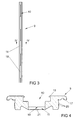
- FIG. 3 shows the adapter profile 9 in one of the window and the espagnolette fitting 3 from FIG. 1 separate condition. It can be seen here that the adapter profile 9 has a plurality of recesses 11, 18 at intended intervals in the bottom region of the receiving tub 10. These recesses 11, 18 serve to carry out the in FIG. 1 4. If in one embodiment of the in FIG. 1 Window shown no or less fittings 4 are used, the recesses 11, 18 are covered in the assembled state of the face-plate 5.
- FIG. 4 shows the adapter profile 9 FIG. 3 In a sectional view along the line IV - IV. It can be seen that the receptacle 10 of the adapter profile 9 has a material constriction 19.
- the Materialeinschnürung 19 is formed as an elongated, arranged in the bottom region of the receptacle 10 notch and allows easy bending of the adapter profile 9 for mounting and dismounting the faceplate 5.
- the outside of the receptacle 10 of the adapter profile 9 is designed to be tapered in cross section to the bottom area and allows Thus, a simple impressions of the adapter profile 9 in the profile 8 of the wing 2.
- a plurality of elongated projections 20 are arranged on the outside of the receptacle 10, which dig into the profile groove 8 in the mounted state.
- the paragraph 15 for supporting the face-plate 5 opposite side of the bottom portion of the receptacle 10 has centrally a stop 21, with which the adapter profile 9 is supported in the profile 8. This is a delay of the adapter profile 9 by the in FIG. 2 shown fastening screws 22 prevented.
Landscapes
- Engineering & Computer Science (AREA)
- Mechanical Engineering (AREA)
- Specific Sealing Or Ventilating Devices For Doors And Windows (AREA)
- Securing Of Glass Panes Or The Like (AREA)
Abstract
Description
- Die Erfindung betrifft eine Befestigungseinrichtung einer Stulpschiene eines Treibstangenbeschlages an einer Profilnut einer Tür oder eines Fensters mit einer an der Stulpschiene längsverschieblich geführten Treibstange und mit einem in der Profilnut montierten Adapterprofil.
- Eine solche Befestigungseinrichtung ist beispielsweise aus der
EP 0 916 790 B1 bekannt. Die Stulpschiene und das Adapterprofil sind mit der Tür oder einer Türfüllung verschraubt. Dies führt zu einem hohen Montageaufwand. - Aus der
EP 1 559 856 A1 ist die Befestigung eines Beschlagteils an einem Flügelrahmenprofil mittels eines Halteelements bekannt geworden. Das Halteelement wird mit dem Flügelrahmenprofil verschraubt und mit der Stulpschiene vernietet. Dies führt jedoch ebenfalls zu einem hohen Montageaufwand. - Weiterhin ist aus der
EP 1 085 151 B1 die Befestigung eines Beschlagteils an einem Rahmenprofil eines Fensters bekannt, bei dem das Rahmenprofil einen Rasthaken hat. An dem Rasthaken wird das Beschlagteil eingeklipst. Dies erfordert jedoch ein ausreichend elastisches Material für das Rahmenprofil. Häufig sind Rahmenprofile jedoch aus Holz gefertigt und weisen daher keine Möglichkeit zur Erzeugung eines Rasthakens auf. - Der Erfindung liegt das Problem zugrunde, eine Befestigungseinrichtung der eingangs genannten Art so weiter zu bilden, dass sie eine besonders einfache und kostengünstige Befestigung der Stulpschiene an der Tür oder dem Fenster ermöglicht.
- Dieses Problem wird erfindungsgemäß dadurch gelöst, dass das Adapterprofil eine formschlüssige Verbindung mit der Stulpschiene hat und dass in dem in die Profilnut eingesetzten Zustand des Adapterprofils die formschlüssige Verbindung mit der Stulpschiene gegen ein Lösen gesichert ist.
- Durch diese Gestaltung sind das Adapterprofil und die Stulpschiene im in der Profilnut montierten Zustand fest miteinander verbunden. Dies führt zu einer besonders einfachen und zuverlässigen Befestigung der Stulpschiene. Damit werden auf ein mit der Stulpschiene verbundenes Beschlagteil einwirkende Kräfte von dem Adapterprofil abgestützt. Hierdurch ist es möglich, für unterschiedliche Türen und Fenster standardisierte und damit kostengünstige Beschlagteile zu verwenden und ein für den entsprechenden Zweck angepasste Adapterprofil einzusetzen. Damit ermöglicht die erfindungsgemäße Befestigungseinrichtung die besonders kostengünstige Befestigung des Beschlagteils.
- Die Sicherung der formschlüssigen Verbindung des Adapterprofils mit der Stulpschiene gegen ein Lösen gestaltet sich konstruktiv besonders einfach, wenn das Adapterprofil eine Aufnahmewanne hat, wenn die formschlüssige Verbindung der Stulpschiene in der Innenseite der Aufnahmewanne angeordnet ist und wenn im montierten Zustand die Außenseite der Aufnahmewanne an der Innenseite der Profilnut abgestützt ist. Durch diese Gestaltung lässt sich die formschlüssige Verbindung der Stulpschiene mit dem Adapterprofil durch ein Aufbiegen des Adapterprofils lösen. Im montierten Zustand wird das Aufbiegen des Adapterprofils jedoch verhindert, weil die Aufnahmewanne an der Innenseite der Profilnut abgestützt ist.
- Die formschlüssige Verbindung der Stulpschiene mit dem Adapterprofil gestaltet sich gemäß einer anderen vorteilhaften Weiterbildung der Erfindung konstruktiv besonders einfach, wenn das Adapterprofil seitliche Ränder der die Stulpschiene übergreifende Haltestege hat und die Stulpschiene auf der den Haltestegen gegenüberliegenden Seite abstützt.
- Das Adapterprofil gestaltet sich gemäß einer anderen vorteilhaften Weiterbildung der Erfindung konstruktiv besonders einfach, wenn das Adapterprofil einen Absatz zur Abstützung der Stulpschiene hat.
- Zur Vereinfachung des Aufbiegens des Adapterprofils zur Montage der Stulpschiene trägt es gemäß einer anderen vorteilhaften Weiterbildung der Erfindung bei, wenn längs der Aufnahmewanne des Adapterprofils eine Materialeinschnürung angeordnet ist. Die Materialeinschnürung verringert die Festigkeit des Adapterprofils quer zu seiner längsten Erstreckung und vereinfacht hierdurch das Aufbiegen. Diese Gestaltung trägt zur Vereinfachung der Montage und der Demontage der Stulpschiene an dem Adapterprofil bei.
- Die Materialeinschnürung gestaltet sich gemäß einer anderen vorteilhaften Weiterbildung der Erfindung konstruktiv besonders einfach, wenn die Materialeinschnürung als im Bodenbereich der Aufnahmewanne angeordnete Kerbe ausgebildet ist.
- Das Adapterprofil lässt sich gemäß einer anderen vorteilhaften Weiterbildung der Erfindung besonders kostengünstig fertigen, wenn das Adapterprofil aus Kunststoff im Extrusionsverfahren gefertigt ist. Solche, im Extrusionsverfahren gefertigte Adapterprofile lassen sich einfach auf die gewünschte Länge schneiden und damit für das jeweilige Einsatzgebiet anpassen.
- Häufig bilden Beschlagteile mit Schlössern und dergleichen vormontierte Baugruppen. Eine Anpassung des Adapterprofils auf die jeweiligen Baugruppen lässt sich gemäß einer anderen vorteilhaften Weiterbildung der Erfindung häufig vermeiden, wenn das Adapterprofil in vorgesehenen Abständen im Bodenbereich Ausnehmungen aufweist. Da die Schlösser häufig in vorgesehenen Abständen an die Stulpschiene montiert sind und zudem bekannte Abmessungen aufweisen, können die Ausnehmungen in dem Adapterprofil zur Aufnahme der Schlösser vorbereitet sein. Im montierten Zustand des Beschlagteils nicht benötigte Ausnehmungen werden von der Stulpschiene abgedeckt. Im einfachsten Fall sind die Ausnehmungen in einem Rastermaß, beispielsweise vier pro laufenden Meter, angeordnet und weisen die Abmessungen von bekannten Schlössern auf.
- Eine hohe Klemmkraft zur Halterung des Adapterprofils lässt sich gemäß einer anderen vorteilhaften Weiterbildung der Erfindung erreichen, wenn die Außenseite der Aufnahmewanne des Adapterprofils im Querschnitt verjüngend gestaltet ist. Weiterhin werden durch diese Gestaltung Toleranzen zwischen der Profilnut und der Außenseite der Aufnahmewanne ausgeglichen. Vorzugsweise hat die Außenseite der Aufnahmewanne zudem in Längsrichtung weisende Erhebungen, mit denen sich das Adapterprofil in der Profilnut verhaken kann.
- Das Adapterprofil ermöglicht gemäß einer anderen vorteilhaften Weiterbildung der Erfindung einen Schutz der Tür gegen Feuchtigkeit, wenn das Adapterprofil an seinen seitlichen Begrenzungen angeordnete Dichtränder hat und wenn die Dichtränder im montierten Zustand an eine an die Profilnut angrenzende Fläche anliegen. Damit ist die erfindungsgemäße Befestigungseinrichtung besonders für Türen und Fenster mit aus Holz gefertigten Flügeln geeignet.
- Das Beschlagteil wird gemäß einer anderen vorteilhaften Weiterbildung der Erfindung gegenüber der Tür oder dem Fenster zuverlässig ausgerichtet, wenn die Aufnahmewanne an ihrer der Stulpschiene abgewandten Seite mittig einen Anschlag zur Abstützung in der Profilnut hat.
- Die Erfindung lässt zahlreiche Ausführungsformen zu. Zur weiteren Verdeutlichung ihres Grundprinzips ist eine davon in der Zeichnung dargestellt und wird nachfolgend beschrieben. Diese zeigt in
- Fig. 1
- eine Tür mit einem Treibstangenbeschlag,
- Fig. 2
- vergrößert eine Schnittdarstellung durch einen Teilbereich der Tür aus
Figur 1 entlang der Linie II - II mit einer Befestigungseinrichtung, - Fig. 3
- ein Adapterprofil der Befestigungseinrichtung aus
Figur 2 , - Fig. 4
- eine Schnittdarstellung durch das Adapterprofil aus
Figur 3 entlang der Linie IV - IV. -
Figur 1 zeigt eine Tür mit einem gegen einen Rahmen 1 schwenkbaren Flügel 2 und mit einem Treibstangenbeschlag 3. Der Treibstangenbeschlag 3 hat mehrere, als Schlösser ausgebildete Beschlagteile 4, welche mit einer feststehenden Stulpschiene 5 verbunden sind. An der Stulpschiene 5 ist eine Treibstange 6 längsverschieblich geführt. -
Figur 2 zeigt vergrößert eine Schnittdarstellung durch einen Teilbereich des Fensters entlang der Linie II - II. Der Flügel 2 des Fensters weist eine Fläche 7 mit einer eine Profilnut 8 auf, in der ein Adapterprofil 9 angeordnet ist. Das Adapterprofil 9 hat eine lang gestreckte Aufnahmewanne 10 zur Aufnahme der Stulpschiene 5 und der Treibstange 6. Die Stulpschiene 5 hat eine formschlüssige Verbindung 16 in der Aufnahmewanne 10 des Adapterprofils 9. Weiterhin weist das Adapterprofil 9 eine Ausnehmung 11 zur Durchführung des als Schloss ausgebildeten Beschlagteils 4 in eine Tasche 12 des Flügels 2 auf. Das Beschlagteil 4 ist zudem über eine durch die Stulpschiene 5 und das Adapterprofil 9 in den Flügel 2 eingedrehte Befestigungsschraube 22 gehalten. - Das Adapterprofil 9 hat zur Erzeugung der formschlüssigen Verbindung mit der Stulpschiene 5 an der Innenseite der Aufnahmewanne 10 angeordnete Haltestege 13. Die Haltestege 13 übergreifen Ränder 14 der Stulpschiene 5 und spannen sie gegen einen Absatz 15 im Adapterprofil 9 vor. Die formschlüssige Verbindung 16 der Stulpschiene 5 mit dem Adapterprofil 9 lässt sich durch ein Aufbiegen des Adapterprofils 9 lösen. In der dargestellten montierten Stellung stützt sich jedoch die Außenseite der Aufnahmewanne 10 in der Profilnut 8 des Flügels 2 ab. Durch die Abstützung der Aufnahmewanne 10 in der Profilnut 8 kann das Adapterprofil 9 nicht aufgebogen werden und die formschlüssige Verbindung 16 mit der Stulpschiene 5 ist damit gegen ein Lösen gesichert. Weiterhin hat das Adapterprofil 9 auf der an die Profilnut 8 angrenzenden Fläche 7 aufliegende Dichtränder 17.
-
Figur 3 zeigt das Adapterprofil 9 in einem von dem Fenster und dem Treibstangenbeschlag 3 ausFigur 1 getrennten Zustand. Hierbei ist zu erkennen, dass das Adapterprofil 9 in vorgesehenen Abständen im Bodenbereich der Aufnahmewanne 10 mehrere Ausnehmungen 11, 18 aufweist. Diese Ausnehmungen 11, 18 dienen zur Durchführung der inFigur 1 beispielhaft dargestellten Beschlagteile 4. Wenn in einer Ausführungsform des inFigur 1 dargestellten Fensters keine oder weniger Beschlagteile 4 eingesetzt werden, werden die Ausnehmungen 11, 18 im montierten Zustand von der Stulpschiene 5 abgedeckt. -
Figur 4 zeigt das Adapterprofil 9 ausFigur 3 in einer Schnittdarstellung entlang der Linie IV - IV. Hierbei ist zu erkennen, dass die Aufnahmewanne 10 des Adapterprofils 9 eine Materialeinschnürung 19 aufweist. Die Materialeinschnürung 19 ist als lang gestreckte, im Bodenbereich der Aufnahmewanne 10 angeordnete Kerbe ausgebildet und ermöglicht das einfache Aufbiegen des Adapterprofils 9 zur Montage und Demontage der Stulpschiene 5. Die Außenseite der Aufnahmewanne 10 des Adapterprofils 9 ist im Querschnitt zum Bodenbereich hin verjüngend gestaltet und ermöglicht damit ein einfaches Eindrücken des Adapterprofils 9 in die Profilnut 8 des Flügels 2. Zudem sind an der Außenseite der Aufnahmewanne 10 mehrere lang gestreckte Erhebungen 20 angeordnet, welche sich im montierten Zustand in der Profilnut 8 verkrallen. Die dem Absatz 15 zur Abstützung der Stulpschiene 5 abgewandte Seite des Bodenbereichs der Aufnahmewanne 10 hat mittig einen Anschlag 21, mit dem sich das Adapterprofil 9 in der Profilnut 8 abstützt. Damit wird ein Verzug des Adapterprofils 9 durch die inFigur 2 dargestellten Befestigungsschrauben 22 verhindert.
Claims (11)
- Befestigungseinrichtung einer Stulpschiene (5) eines Treibstangenbeschlages (3) an einer Profilnut (8) einer Tür oder eines Fensters mit einer an der Stulpschiene (5) längsverschieblich geführten Treibstange (6) und mit einem in der Profilnut (8) montierten Adapterprofil (9), dadurch gekennzeichnet, dass das Adapterprofil (9) eine formschlüssige Verbindung (16) mit der Stulpschiene (5) hat und dass in dem in die Profilnut (8) eingesetzten Zustand des Adapterprofils (9) die formschlüssige Verbindung (16) mit der Stulpschiene (5) gegen ein Lösen gesichert ist.
- Befestigungseinrichtung nach Anspruch 1, dadurch gekennzeichnet, dass das Adapterprofil (9) eine Aufnahmewanne (10) hat, dass die formschlüssige Verbindung (16) der Stulpschiene (5) in der Innenseite der Aufnahmewanne (10) angeordnet ist und dass im montierten Zustand die Außenseite der Aufnahmewanne (10) an der Innenseite der Profilnut (8) abgestützt ist.
- Befestigungseinrichtung nach Anspruch 1 oder 2, dadurch gekennzeichnet, dass das Adapterprofil (9) seitliche Ränder (14) der die Stulpschiene (5) übergreifende Haltestege (13) hat und die Stulpschiene (5) auf der den Haltestegen (13) gegenüberliegenden Seite abstützt.
- Befestigungseinrichtung nach Anspruch 3, dadurch gekennzeichnet, dass das Adapterprofil (9) einen Absatz (15) zur Abstützung der Stulpschiene (5) hat.
- Befestigungseinrichtung nach einem der Ansprüche 2 bis 4, dadurch gekennzeichnet, dass längs der Aufnahmewanne (10) des Adapterprofils (9) eine Materialeinschnürung (19) angeordnet ist.
- Befestigungseinrichtung nach Anspruch 5, dadurch gekennzeichnet, dass die Materialeinschnürung (19) als im Bodenbereich der Aufnahmewanne (10) angeordnete Kerbe ausgebildet ist.
- Befestigungseinrichtung nach einem der vorhergehenden Ansprüchen, dadurch gekennzeichnet, dass das Adapterprofil (9) aus Kunststoff im Extrusionsverfahren gefertigt ist.
- Befestigungseinrichtung nach einem der vorhergehenden Ansprüchen, dadurch gekennzeichnet, dass das Adapterprofil (9) in vorgesehenen Abständen im Bodenbereich Ausnehmungen (11, 18) aufweist.
- Befestigungseinrichtung nach einem der Ansprüche 2 bis 8, dadurch gekennzeichnet, dass die Außenseite der Aufnahmewanne (10) des Adapterprofils (9) im Querschnitt verjüngend gestaltet ist.
- Befestigungseinrichtung nach einem der vorhergehenden Ansprüchen, dadurch gekennzeichnet, dass das Adapterprofil (9) an seinen seitlichen Begrenzungen angeordnete Dichtränder (17) hat und dass die Dichtränder (17) im montierten Zustand an eine an die Profilnut (8) angrenzende Fläche (7) anliegen.
- Befestigungseinrichtung nach einem der Ansprüche 2 bis 10, dadurch gekennzeichnet, dass die Aufnahmewanne (10) an ihrer der Stulpschiene (5) abgewandten Seite mittig einen Anschlag (21) zur Abstützung in der Profilnut (8) hat.
Applications Claiming Priority (1)
| Application Number | Priority Date | Filing Date | Title |
|---|---|---|---|
| DE201010062309 DE102010062309A1 (de) | 2010-12-01 | 2010-12-01 | Befestigungseinrichtung einer Stulpschiene eines Treibstangenbeschlages |
Publications (3)
| Publication Number | Publication Date |
|---|---|
| EP2460961A2 true EP2460961A2 (de) | 2012-06-06 |
| EP2460961A3 EP2460961A3 (de) | 2017-11-01 |
| EP2460961B1 EP2460961B1 (de) | 2018-10-17 |
Family
ID=45092209
Family Applications (1)
| Application Number | Title | Priority Date | Filing Date |
|---|---|---|---|
| EP11188606.5A Active EP2460961B1 (de) | 2010-12-01 | 2011-11-10 | Befestigungseinrichtung einer Stulpschiene eines Treibstangenbeschlages |
Country Status (2)
| Country | Link |
|---|---|
| EP (1) | EP2460961B1 (de) |
| DE (1) | DE102010062309A1 (de) |
Citations (3)
| Publication number | Priority date | Publication date | Assignee | Title |
|---|---|---|---|---|
| EP0916790B1 (de) | 1997-11-12 | 2003-03-05 | Alprokon Promotie En Ontwikkeling B.V. | Einbruchhemmendes Profil für die Kante einer Tür |
| EP1085151B1 (de) | 1999-09-09 | 2005-01-26 | ROTO FRANK Aktiengesellschaft | Fenster, Tür oder dergleichen sowie Rahmenprofil hierfür |
| EP1559856A1 (de) | 2004-01-27 | 2005-08-03 | Roto Frank Ag | Fenster, Tür oder dergleichen sowie Flügelrahmenprofil und Stulpschienenbeschlag hierfür |
Family Cites Families (7)
| Publication number | Priority date | Publication date | Assignee | Title |
|---|---|---|---|---|
| BE744166A (nl) * | 1970-01-08 | 1970-06-15 | P V B A Vancraeynest Gebroeder | Grendel. |
| DE8117338U1 (de) * | 1981-06-11 | 1981-08-20 | Wilh. Frank Gmbh, 7022 Leinfelden-Echterdingen | Vorrichtung zum befestigen einer stulpschiene und zur fuehrung einer treibstange eines ablaengbaren treibstangenbeschlags |
| DE29712614U1 (de) * | 1997-07-17 | 1998-03-19 | Gretsch-Unitas GmbH Baubeschläge, 71254 Ditzingen | Stulpschienenbeschlag |
| DE29716501U1 (de) * | 1997-09-13 | 1999-01-28 | Roto Frank Ag, 70771 Leinfelden-Echterdingen | Halter zum Befestigen von Stulpschienen an Fenstern, Türen o.dgl. |
| DE29803656U1 (de) * | 1998-03-03 | 1998-04-23 | Wilhelm Weidtmann GmbH & Co KG, 42551 Velbert | Tür- oder Fensterbeschlag |
| FR2897382B1 (fr) * | 2006-02-13 | 2008-04-25 | Stremler Soc Par Actions Simpl | "dispositif de verrouillage a au moins un point de condamnation" |
| FR2938888B1 (fr) * | 2008-11-27 | 2010-12-10 | Metalux | Dispositif de fixation de tetiere. |
-
2010
- 2010-12-01 DE DE201010062309 patent/DE102010062309A1/de not_active Withdrawn
-
2011
- 2011-11-10 EP EP11188606.5A patent/EP2460961B1/de active Active
Patent Citations (3)
| Publication number | Priority date | Publication date | Assignee | Title |
|---|---|---|---|---|
| EP0916790B1 (de) | 1997-11-12 | 2003-03-05 | Alprokon Promotie En Ontwikkeling B.V. | Einbruchhemmendes Profil für die Kante einer Tür |
| EP1085151B1 (de) | 1999-09-09 | 2005-01-26 | ROTO FRANK Aktiengesellschaft | Fenster, Tür oder dergleichen sowie Rahmenprofil hierfür |
| EP1559856A1 (de) | 2004-01-27 | 2005-08-03 | Roto Frank Ag | Fenster, Tür oder dergleichen sowie Flügelrahmenprofil und Stulpschienenbeschlag hierfür |
Also Published As
| Publication number | Publication date |
|---|---|
| EP2460961B1 (de) | 2018-10-17 |
| EP2460961A3 (de) | 2017-11-01 |
| DE102010062309A1 (de) | 2012-06-21 |
Similar Documents
| Publication | Publication Date | Title |
|---|---|---|
| DE202018104747U1 (de) | Vorrichtung zur Gebäudeeinbruchsicherung | |
| DE202007004060U1 (de) | Gebäudeabschluss in sprengwirkungshemmender Ausführung | |
| DE202009005885U1 (de) | Treibstangenschloss mit Falle und Schubriegel | |
| EP2450519A1 (de) | Gebäudeabschluss in einbruchhemmender Ausführung | |
| DE202006005098U1 (de) | Rahmenbaugruppe | |
| EP2460961B1 (de) | Befestigungseinrichtung einer Stulpschiene eines Treibstangenbeschlages | |
| EP0725202B1 (de) | Bewehrung an Türen oder Fenstern | |
| AT522348B1 (de) | Befestigungssystem für Absturzsicherung | |
| EP2099989B1 (de) | Treibstangengetriebe | |
| EP2339095B1 (de) | Tür, insbesondere Kunstofftür, mit einer Schlosskastensicherung | |
| EP3441547B1 (de) | Schliessblech für einen treibstangenbeschlag | |
| DE102004055803A1 (de) | Rahmenloses Isolierglaselement sowie Beschlag- oder Befestigungssystem für das Isolierglaselement | |
| DE202005000629U1 (de) | T-Verbinder für eine aus Pfosten- und quer dazu verlaufenden Riegelprofilen gebildeten Fachwerkkonstruktion | |
| EP1559856B1 (de) | Fenster, Tür oder dergleichen mit einem Stulpschienenbeschlag | |
| DE202020000211U1 (de) | Distanzstück und System zum dauerhaften Befestigen eines Bauteils an wenigstens einem Befestigungspunkt | |
| DE102015206906A1 (de) | Fenster, Tür oder dergleichen, mit mindestens einer Verschlussvorrichtung | |
| DE202018104841U1 (de) | Verschlusselement zum Verschließen einer Öffnung | |
| DE3924054C2 (de) | Fensterrahmen, insbesondere aus Kunststoff und insbesondere für Kellerfenster | |
| EP2378045A2 (de) | Isolierglasscheibe | |
| EP2216471A2 (de) | Anordnung mit einem Montageteil für ein Scharnier an einer Platte | |
| DE102022120797A1 (de) | Isoliersteg zum Verbinden zweier Profilelemente zur Herstellung eines wärmegedämmten Profils und ein solches Profil | |
| DE1921370A1 (de) | Treibstangenbeschlag fuer Fensterfluegel od.dgl. | |
| DE102013101891B4 (de) | Riegelstück und Montageverfahren eines Riegelstücks | |
| EP1997988B1 (de) | Kantengetriebe zum Antrieb eines Treibstangenbeschlages eines Fensters | |
| EP4083355A1 (de) | Beschlagelement sowie fenster oder tür mit einem beschlagelement |
Legal Events
| Date | Code | Title | Description |
|---|---|---|---|
| PUAI | Public reference made under article 153(3) epc to a published international application that has entered the european phase |
Free format text: ORIGINAL CODE: 0009012 |
|
| AK | Designated contracting states |
Kind code of ref document: A2 Designated state(s): AL AT BE BG CH CY CZ DE DK EE ES FI FR GB GR HR HU IE IS IT LI LT LU LV MC MK MT NL NO PL PT RO RS SE SI SK SM TR |
|
| AX | Request for extension of the european patent |
Extension state: BA ME |
|
| PUAL | Search report despatched |
Free format text: ORIGINAL CODE: 0009013 |
|
| AK | Designated contracting states |
Kind code of ref document: A3 Designated state(s): AL AT BE BG CH CY CZ DE DK EE ES FI FR GB GR HR HU IE IS IT LI LT LU LV MC MK MT NL NO PL PT RO RS SE SI SK SM TR |
|
| AX | Request for extension of the european patent |
Extension state: BA ME |
|
| RIC1 | Information provided on ipc code assigned before grant |
Ipc: E05C 9/00 20060101AFI20170928BHEP Ipc: E05C 9/22 20060101ALI20170928BHEP |
|
| 17P | Request for examination filed |
Effective date: 20180327 |
|
| RBV | Designated contracting states (corrected) |
Designated state(s): AL AT BE BG CH CY CZ DE DK EE ES FI FR GB GR HR HU IE IS IT LI LT LU LV MC MK MT NL NO PL PT RO RS SE SI SK SM TR |
|
| GRAP | Despatch of communication of intention to grant a patent |
Free format text: ORIGINAL CODE: EPIDOSNIGR1 |
|
| INTG | Intention to grant announced |
Effective date: 20180613 |
|
| GRAS | Grant fee paid |
Free format text: ORIGINAL CODE: EPIDOSNIGR3 |
|
| GRAA | (expected) grant |
Free format text: ORIGINAL CODE: 0009210 |
|
| AK | Designated contracting states |
Kind code of ref document: B1 Designated state(s): AL AT BE BG CH CY CZ DE DK EE ES FI FR GB GR HR HU IE IS IT LI LT LU LV MC MK MT NL NO PL PT RO RS SE SI SK SM TR |
|
| REG | Reference to a national code |
Ref country code: GB Ref legal event code: FG4D Free format text: NOT ENGLISH |
|
| REG | Reference to a national code |
Ref country code: CH Ref legal event code: EP |
|
| REG | Reference to a national code |
Ref country code: IE Ref legal event code: FG4D Free format text: LANGUAGE OF EP DOCUMENT: GERMAN |
|
| REG | Reference to a national code |
Ref country code: DE Ref legal event code: R096 Ref document number: 502011014862 Country of ref document: DE Ref country code: AT Ref legal event code: REF Ref document number: 1054223 Country of ref document: AT Kind code of ref document: T Effective date: 20181115 |
|
| REG | Reference to a national code |
Ref country code: NL Ref legal event code: MP Effective date: 20181017 |
|
| REG | Reference to a national code |
Ref country code: LT Ref legal event code: MG4D |
|
| PG25 | Lapsed in a contracting state [announced via postgrant information from national office to epo] |
Ref country code: NL Free format text: LAPSE BECAUSE OF FAILURE TO SUBMIT A TRANSLATION OF THE DESCRIPTION OR TO PAY THE FEE WITHIN THE PRESCRIBED TIME-LIMIT Effective date: 20181017 |
|
| PG25 | Lapsed in a contracting state [announced via postgrant information from national office to epo] |
Ref country code: HR Free format text: LAPSE BECAUSE OF FAILURE TO SUBMIT A TRANSLATION OF THE DESCRIPTION OR TO PAY THE FEE WITHIN THE PRESCRIBED TIME-LIMIT Effective date: 20181017 Ref country code: LT Free format text: LAPSE BECAUSE OF FAILURE TO SUBMIT A TRANSLATION OF THE DESCRIPTION OR TO PAY THE FEE WITHIN THE PRESCRIBED TIME-LIMIT Effective date: 20181017 Ref country code: PL Free format text: LAPSE BECAUSE OF FAILURE TO SUBMIT A TRANSLATION OF THE DESCRIPTION OR TO PAY THE FEE WITHIN THE PRESCRIBED TIME-LIMIT Effective date: 20181017 Ref country code: BG Free format text: LAPSE BECAUSE OF FAILURE TO SUBMIT A TRANSLATION OF THE DESCRIPTION OR TO PAY THE FEE WITHIN THE PRESCRIBED TIME-LIMIT Effective date: 20190117 Ref country code: ES Free format text: LAPSE BECAUSE OF FAILURE TO SUBMIT A TRANSLATION OF THE DESCRIPTION OR TO PAY THE FEE WITHIN THE PRESCRIBED TIME-LIMIT Effective date: 20181017 Ref country code: IS Free format text: LAPSE BECAUSE OF FAILURE TO SUBMIT A TRANSLATION OF THE DESCRIPTION OR TO PAY THE FEE WITHIN THE PRESCRIBED TIME-LIMIT Effective date: 20190217 Ref country code: NO Free format text: LAPSE BECAUSE OF FAILURE TO SUBMIT A TRANSLATION OF THE DESCRIPTION OR TO PAY THE FEE WITHIN THE PRESCRIBED TIME-LIMIT Effective date: 20190117 Ref country code: FI Free format text: LAPSE BECAUSE OF FAILURE TO SUBMIT A TRANSLATION OF THE DESCRIPTION OR TO PAY THE FEE WITHIN THE PRESCRIBED TIME-LIMIT Effective date: 20181017 Ref country code: LV Free format text: LAPSE BECAUSE OF FAILURE TO SUBMIT A TRANSLATION OF THE DESCRIPTION OR TO PAY THE FEE WITHIN THE PRESCRIBED TIME-LIMIT Effective date: 20181017 |
|
| PG25 | Lapsed in a contracting state [announced via postgrant information from national office to epo] |
Ref country code: RS Free format text: LAPSE BECAUSE OF FAILURE TO SUBMIT A TRANSLATION OF THE DESCRIPTION OR TO PAY THE FEE WITHIN THE PRESCRIBED TIME-LIMIT Effective date: 20181017 Ref country code: SE Free format text: LAPSE BECAUSE OF FAILURE TO SUBMIT A TRANSLATION OF THE DESCRIPTION OR TO PAY THE FEE WITHIN THE PRESCRIBED TIME-LIMIT Effective date: 20181017 Ref country code: AL Free format text: LAPSE BECAUSE OF FAILURE TO SUBMIT A TRANSLATION OF THE DESCRIPTION OR TO PAY THE FEE WITHIN THE PRESCRIBED TIME-LIMIT Effective date: 20181017 Ref country code: PT Free format text: LAPSE BECAUSE OF FAILURE TO SUBMIT A TRANSLATION OF THE DESCRIPTION OR TO PAY THE FEE WITHIN THE PRESCRIBED TIME-LIMIT Effective date: 20190217 Ref country code: GR Free format text: LAPSE BECAUSE OF FAILURE TO SUBMIT A TRANSLATION OF THE DESCRIPTION OR TO PAY THE FEE WITHIN THE PRESCRIBED TIME-LIMIT Effective date: 20190118 |
|
| REG | Reference to a national code |
Ref country code: CH Ref legal event code: PL |
|
| REG | Reference to a national code |
Ref country code: DE Ref legal event code: R097 Ref document number: 502011014862 Country of ref document: DE |
|
| PG25 | Lapsed in a contracting state [announced via postgrant information from national office to epo] |
Ref country code: LU Free format text: LAPSE BECAUSE OF NON-PAYMENT OF DUE FEES Effective date: 20181110 Ref country code: DK Free format text: LAPSE BECAUSE OF FAILURE TO SUBMIT A TRANSLATION OF THE DESCRIPTION OR TO PAY THE FEE WITHIN THE PRESCRIBED TIME-LIMIT Effective date: 20181017 Ref country code: CZ Free format text: LAPSE BECAUSE OF FAILURE TO SUBMIT A TRANSLATION OF THE DESCRIPTION OR TO PAY THE FEE WITHIN THE PRESCRIBED TIME-LIMIT Effective date: 20181017 Ref country code: IT Free format text: LAPSE BECAUSE OF FAILURE TO SUBMIT A TRANSLATION OF THE DESCRIPTION OR TO PAY THE FEE WITHIN THE PRESCRIBED TIME-LIMIT Effective date: 20181017 |
|
| REG | Reference to a national code |
Ref country code: BE Ref legal event code: MM Effective date: 20181130 |
|
| REG | Reference to a national code |
Ref country code: IE Ref legal event code: MM4A |
|
| PLBE | No opposition filed within time limit |
Free format text: ORIGINAL CODE: 0009261 |
|
| STAA | Information on the status of an ep patent application or granted ep patent |
Free format text: STATUS: NO OPPOSITION FILED WITHIN TIME LIMIT |
|
| PG25 | Lapsed in a contracting state [announced via postgrant information from national office to epo] |
Ref country code: LI Free format text: LAPSE BECAUSE OF NON-PAYMENT OF DUE FEES Effective date: 20181130 Ref country code: RO Free format text: LAPSE BECAUSE OF FAILURE TO SUBMIT A TRANSLATION OF THE DESCRIPTION OR TO PAY THE FEE WITHIN THE PRESCRIBED TIME-LIMIT Effective date: 20181017 Ref country code: CH Free format text: LAPSE BECAUSE OF NON-PAYMENT OF DUE FEES Effective date: 20181130 Ref country code: EE Free format text: LAPSE BECAUSE OF FAILURE TO SUBMIT A TRANSLATION OF THE DESCRIPTION OR TO PAY THE FEE WITHIN THE PRESCRIBED TIME-LIMIT Effective date: 20181017 Ref country code: SM Free format text: LAPSE BECAUSE OF FAILURE TO SUBMIT A TRANSLATION OF THE DESCRIPTION OR TO PAY THE FEE WITHIN THE PRESCRIBED TIME-LIMIT Effective date: 20181017 Ref country code: SK Free format text: LAPSE BECAUSE OF FAILURE TO SUBMIT A TRANSLATION OF THE DESCRIPTION OR TO PAY THE FEE WITHIN THE PRESCRIBED TIME-LIMIT Effective date: 20181017 Ref country code: MC Free format text: LAPSE BECAUSE OF FAILURE TO SUBMIT A TRANSLATION OF THE DESCRIPTION OR TO PAY THE FEE WITHIN THE PRESCRIBED TIME-LIMIT Effective date: 20181017 |
|
| 26N | No opposition filed |
Effective date: 20190718 |
|
| PG25 | Lapsed in a contracting state [announced via postgrant information from national office to epo] |
Ref country code: IE Free format text: LAPSE BECAUSE OF NON-PAYMENT OF DUE FEES Effective date: 20181110 Ref country code: SI Free format text: LAPSE BECAUSE OF FAILURE TO SUBMIT A TRANSLATION OF THE DESCRIPTION OR TO PAY THE FEE WITHIN THE PRESCRIBED TIME-LIMIT Effective date: 20181017 |
|
| PG25 | Lapsed in a contracting state [announced via postgrant information from national office to epo] |
Ref country code: BE Free format text: LAPSE BECAUSE OF NON-PAYMENT OF DUE FEES Effective date: 20181130 |
|
| PG25 | Lapsed in a contracting state [announced via postgrant information from national office to epo] |
Ref country code: MT Free format text: LAPSE BECAUSE OF FAILURE TO SUBMIT A TRANSLATION OF THE DESCRIPTION OR TO PAY THE FEE WITHIN THE PRESCRIBED TIME-LIMIT Effective date: 20181017 |
|
| PG25 | Lapsed in a contracting state [announced via postgrant information from national office to epo] |
Ref country code: TR Free format text: LAPSE BECAUSE OF FAILURE TO SUBMIT A TRANSLATION OF THE DESCRIPTION OR TO PAY THE FEE WITHIN THE PRESCRIBED TIME-LIMIT Effective date: 20181017 |
|
| PGFP | Annual fee paid to national office [announced via postgrant information from national office to epo] |
Ref country code: AT Payment date: 20191121 Year of fee payment: 9 |
|
| PG25 | Lapsed in a contracting state [announced via postgrant information from national office to epo] |
Ref country code: HU Free format text: LAPSE BECAUSE OF FAILURE TO SUBMIT A TRANSLATION OF THE DESCRIPTION OR TO PAY THE FEE WITHIN THE PRESCRIBED TIME-LIMIT; INVALID AB INITIO Effective date: 20111110 Ref country code: MK Free format text: LAPSE BECAUSE OF NON-PAYMENT OF DUE FEES Effective date: 20181017 Ref country code: CY Free format text: LAPSE BECAUSE OF FAILURE TO SUBMIT A TRANSLATION OF THE DESCRIPTION OR TO PAY THE FEE WITHIN THE PRESCRIBED TIME-LIMIT Effective date: 20181017 |
|
| PGFP | Annual fee paid to national office [announced via postgrant information from national office to epo] |
Ref country code: FR Payment date: 20201126 Year of fee payment: 10 |
|
| REG | Reference to a national code |
Ref country code: AT Ref legal event code: MM01 Ref document number: 1054223 Country of ref document: AT Kind code of ref document: T Effective date: 20201110 |
|
| PG25 | Lapsed in a contracting state [announced via postgrant information from national office to epo] |
Ref country code: AT Free format text: LAPSE BECAUSE OF NON-PAYMENT OF DUE FEES Effective date: 20201110 |
|
| PGFP | Annual fee paid to national office [announced via postgrant information from national office to epo] |
Ref country code: DE Payment date: 20211122 Year of fee payment: 11 |
|
| PG25 | Lapsed in a contracting state [announced via postgrant information from national office to epo] |
Ref country code: FR Free format text: LAPSE BECAUSE OF NON-PAYMENT OF DUE FEES Effective date: 20211130 |
|
| REG | Reference to a national code |
Ref country code: DE Ref legal event code: R119 Ref document number: 502011014862 Country of ref document: DE |
|
| P01 | Opt-out of the competence of the unified patent court (upc) registered |
Effective date: 20230512 |
|
| PG25 | Lapsed in a contracting state [announced via postgrant information from national office to epo] |
Ref country code: DE Free format text: LAPSE BECAUSE OF NON-PAYMENT OF DUE FEES Effective date: 20230601 |
|
| PGFP | Annual fee paid to national office [announced via postgrant information from national office to epo] |
Ref country code: GB Payment date: 20241121 Year of fee payment: 14 |