EP2456998B1 - Dämpfungseinrichtung - Google Patents
Dämpfungseinrichtung Download PDFInfo
- Publication number
- EP2456998B1 EP2456998B1 EP10737822.6A EP10737822A EP2456998B1 EP 2456998 B1 EP2456998 B1 EP 2456998B1 EP 10737822 A EP10737822 A EP 10737822A EP 2456998 B1 EP2456998 B1 EP 2456998B1
- Authority
- EP
- European Patent Office
- Prior art keywords
- damping
- damping device
- bypass channel
- bellows
- channel
- Prior art date
- Legal status (The legal status is an assumption and is not a legal conclusion. Google has not performed a legal analysis and makes no representation as to the accuracy of the status listed.)
- Not-in-force
Links
- 238000013016 damping Methods 0.000 title claims description 128
- 229920001169 thermoplastic Polymers 0.000 claims description 6
- 229920002725 thermoplastic elastomer Polymers 0.000 claims description 6
- 239000004416 thermosoftening plastic Substances 0.000 claims description 6
- 238000000034 method Methods 0.000 claims description 3
- 230000005540 biological transmission Effects 0.000 description 9
- 230000000694 effects Effects 0.000 description 9
- 239000012530 fluid Substances 0.000 description 5
- 230000033001 locomotion Effects 0.000 description 5
- 239000007769 metal material Substances 0.000 description 2
- 239000004033 plastic Substances 0.000 description 2
- 238000004026 adhesive bonding Methods 0.000 description 1
- 230000007423 decrease Effects 0.000 description 1
- 230000001419 dependent effect Effects 0.000 description 1
- 230000002349 favourable effect Effects 0.000 description 1
- 239000000446 fuel Substances 0.000 description 1
- 239000000463 material Substances 0.000 description 1
- 230000007935 neutral effect Effects 0.000 description 1
- 238000005086 pumping Methods 0.000 description 1
- 230000035939 shock Effects 0.000 description 1
- 230000003068 static effect Effects 0.000 description 1
Images


Classifications
-
- F—MECHANICAL ENGINEERING; LIGHTING; HEATING; WEAPONS; BLASTING
- F16—ENGINEERING ELEMENTS AND UNITS; GENERAL MEASURES FOR PRODUCING AND MAINTAINING EFFECTIVE FUNCTIONING OF MACHINES OR INSTALLATIONS; THERMAL INSULATION IN GENERAL
- F16F—SPRINGS; SHOCK-ABSORBERS; MEANS FOR DAMPING VIBRATION
- F16F9/00—Springs, vibration-dampers, shock-absorbers, or similarly-constructed movement-dampers using a fluid or the equivalent as damping medium
- F16F9/02—Springs, vibration-dampers, shock-absorbers, or similarly-constructed movement-dampers using a fluid or the equivalent as damping medium using gas only or vacuum
- F16F9/04—Springs, vibration-dampers, shock-absorbers, or similarly-constructed movement-dampers using a fluid or the equivalent as damping medium using gas only or vacuum in a chamber with a flexible wall
-
- F—MECHANICAL ENGINEERING; LIGHTING; HEATING; WEAPONS; BLASTING
- F16—ENGINEERING ELEMENTS AND UNITS; GENERAL MEASURES FOR PRODUCING AND MAINTAINING EFFECTIVE FUNCTIONING OF MACHINES OR INSTALLATIONS; THERMAL INSULATION IN GENERAL
- F16F—SPRINGS; SHOCK-ABSORBERS; MEANS FOR DAMPING VIBRATION
- F16F9/00—Springs, vibration-dampers, shock-absorbers, or similarly-constructed movement-dampers using a fluid or the equivalent as damping medium
- F16F9/02—Springs, vibration-dampers, shock-absorbers, or similarly-constructed movement-dampers using a fluid or the equivalent as damping medium using gas only or vacuum
- F16F9/04—Springs, vibration-dampers, shock-absorbers, or similarly-constructed movement-dampers using a fluid or the equivalent as damping medium using gas only or vacuum in a chamber with a flexible wall
- F16F9/0472—Springs, vibration-dampers, shock-absorbers, or similarly-constructed movement-dampers using a fluid or the equivalent as damping medium using gas only or vacuum in a chamber with a flexible wall characterised by comprising a damping device
- F16F9/0481—Springs, vibration-dampers, shock-absorbers, or similarly-constructed movement-dampers using a fluid or the equivalent as damping medium using gas only or vacuum in a chamber with a flexible wall characterised by comprising a damping device provided in an opening to the exterior atmosphere
-
- F—MECHANICAL ENGINEERING; LIGHTING; HEATING; WEAPONS; BLASTING
- F16—ENGINEERING ELEMENTS AND UNITS; GENERAL MEASURES FOR PRODUCING AND MAINTAINING EFFECTIVE FUNCTIONING OF MACHINES OR INSTALLATIONS; THERMAL INSULATION IN GENERAL
- F16F—SPRINGS; SHOCK-ABSORBERS; MEANS FOR DAMPING VIBRATION
- F16F15/00—Suppression of vibrations in systems; Means or arrangements for avoiding or reducing out-of-balance forces, e.g. due to motion
-
- F—MECHANICAL ENGINEERING; LIGHTING; HEATING; WEAPONS; BLASTING
- F16—ENGINEERING ELEMENTS AND UNITS; GENERAL MEASURES FOR PRODUCING AND MAINTAINING EFFECTIVE FUNCTIONING OF MACHINES OR INSTALLATIONS; THERMAL INSULATION IN GENERAL
- F16F—SPRINGS; SHOCK-ABSORBERS; MEANS FOR DAMPING VIBRATION
- F16F15/00—Suppression of vibrations in systems; Means or arrangements for avoiding or reducing out-of-balance forces, e.g. due to motion
- F16F15/02—Suppression of vibrations of non-rotating, e.g. reciprocating systems; Suppression of vibrations of rotating systems by use of members not moving with the rotating systems
- F16F15/023—Suppression of vibrations of non-rotating, e.g. reciprocating systems; Suppression of vibrations of rotating systems by use of members not moving with the rotating systems using fluid means
- F16F15/027—Suppression of vibrations of non-rotating, e.g. reciprocating systems; Suppression of vibrations of rotating systems by use of members not moving with the rotating systems using fluid means comprising control arrangements
Definitions
- the present invention relates to a damping device for damping of attack and Abstelloeuvre an automotive engine, having a first and second chamber, which are filled with a damping medium and separated by an intermediate plate, wherein the chambers are each bounded by a bellows and a face plate, wherein in the intermediate plate a chamber connecting the damping channels is introduced, wherein both chambers are connected to at least one bypass channel, and wherein the bypass channel is releasable or closable by means of a switchable valve. Furthermore, the invention relates to a damping system with such a damping device.
- the damping device has an intermediate plate and two extending in the longitudinal direction of the intermediate plate in each case in the opposite direction wegerumblende Bellows on. At their end faces, the bellows are closed by means of a plate so that two working chambers are formed. Both chambers are connected to each other via a channel in the intermediate plate.
- a compressible fluid in particular air, is used. For damping the compressible fluid flows through the damping channel from one chamber to the other chamber, wherein the damping effect is generated due to the friction occurring in the channel.
- FR 1.112.259 A is a damper out, which has two working chambers, wherein the working chambers are separated by an intermediate plate. Furthermore, the working chambers are limited by a respective intermediate plate and a bellows.
- a damping channel and a bypass channel is introduced, wherein the damping channel is releasable and closable by means of an expansion valve.
- US 5,062,497 A shows a damping device which has two separate by an intermediate plate working chambers, wherein the working chambers are each bounded by an intermediate plate and a bellows.
- the two chambers are connected by a fluid channel, which is releasable and closable by means of a valve.
- a damping device for damping the movements of a motor vehicle engine has two chambers filled with oil, which are separated by an intermediate plate and each bounded by an elastic Umhausung.
- the intermediate plate two channels provided with different cross sections are introduced, which connect the two chambers together.
- the channel with larger cross section can be opened and closed by means of a rotary valve.
- the invention has for its object to provide a damping device that dampens the arrival and Abstellplo a motor vehicle engine and is free from driving a damping effect.
- bypass channel connects the two chambers with the environment that the switching state of the valve depends on the operating condition of the motor vehicle engine and that the bypass channel is closed during the on and off operation of the motor vehicle engine and is open while driving.
- the damping can be changed depending on the operating state of the engine by means of the switchable valve.
- a first switching position of the bypass channel is closed, so that the displaced air flows over the arranged between the chambers damping channel.
- the bypass channel is opened so that the displaced air flows via the bypass channel and not via the damping channel.
- the air is passed over the bypass channel open, so that no damping takes place when driving.
- the damping device according to the invention increases the ride comfort. Since the bypass channel connects the two chambers with the environment, the bypass channel allows leakage of the damping medium from the two chambers into the environment, whereby the damping channel is bridged.
- the bypass channel has a larger cross section than the damping channel.
- bypass channel is introduced in the intermediate plate.
- bypass channel connects the two chambers with each other.
- a first bypass channel is introduced into the first end plate for connecting the first chamber to the environment and a second bypass channel is introduced into the second end plate for connecting the second chamber to the environment.
- valve is designed as a multi-stage or continuously variable valve.
- cross section of the bypass channel can be advantageously adapted to the respective pitch frequency of the motor vehicle engine.
- the valve is advantageously switchable by means of vacuum or electromagnetically. On the one hand, such valves are cost-effective and, on the other hand, have high reliability.
- air is used as the damping medium.
- Air bearings are cheaper compared to hydraulic bearings, as a filling with damping fluid is eliminated.
- the bellows are arranged coaxially to the damping channel.
- the first end plate is attached to the end face of the first bellows and the second end plate is attached to the end face of the second bellows.
- the bellows advantageously have a length of 5 mm to 20 mm, preferably from 5 mm to 10 mm. Furthermore, the bellows advantageously have an outer diameter of from 70 mm to 100 mm, preferably from 80 mm to 90 mm. Due to the dimensions of the bellows a favorable small chamber volume and a large pumping area is provided, so that an effective damping effect can be achieved.
- the bellows are advantageously made of a thermoplastic elastomer (TPE) or a thermoplastic (TP).
- TPE thermoplastic elastomer
- TP thermoplastic
- the present invention relates to a damping system for damping of arrival and Abstellhave a motor vehicle engine having a damping device according to the invention and a control device for controlling the switchable valve of the damping device depending on the operating condition of the motor vehicle engine.
- the switchable valve of the damping device is controlled via the control device as a function of the operating state of the motor vehicle engine.
- the switchable valve is closed during the on and off operation of the motor vehicle engine and opened while driving. Consequently takes place during the on and off of the motor vehicle engine damping and driving is no damping.
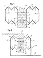
- Fig. 1 shows a damping device 10 which is provided for damping of attack and Abstellplo a transversely mounted motor vehicle engine 47, which has a start-stop system.
- the damping device 10 has an intermediate plate 11, a first bellows 12, a first end plate 13, a second bellows 15 and a second end plate 16.
- the Bellows 12, 15 are connected to the intermediate plate 11 at a first end region. At a second end region, the end plate 13, 16 is provided.
- the intermediate plate 11, the first bellows 12 and the first end plate 13 form a first working chamber 14.
- the intermediate plate 11, the second bellows 15 and the second end plate 16 form a second working chamber 17.
- Both working chambers 14, 17 are in the intermediate plate 11th introduced damping channel 19 connected to each other.
- Within the working chambers 14, 17 is a damping medium 18, in particular air.
- a bypass channel 20 is introduced into the intermediate plate 11, which connects the first chamber 14 and the second chamber 17 with the surroundings.
- the bypass channel 20 has a larger diameter than the damping channel 19.
- the intermediate plate 11 is made of a metallic material, but may also be made of a plastic.
- the bellows 12, 15 are made of a thermoplastic elastomer (TPE) or a thermoplastic (TP) and have a length of 5 mm to 20 mm and an outer diameter of 70 mm to 100 mm.
- the end plates 13, 16 are also made of a metallic material, but may also consist of a plastic.
- the bellows 12, 15 extend away from the intermediate plate coaxially with the damping channel 19, wherein the bellows 12, 15 extend in the opposite direction.
- the open end faces of the bellows 12, 15 are each closed by a front plate 13, 16.
- connection methods such as gluing, used.
- Fig. 1 is attached to the intermediate plate 11 of the damping device 10, a switchable valve 22.
- the switchable valve 22 has an actuator 23 which is in a known manner by means of vacuum or electromagnetically switchable.
- the actuator 23 opens or closes the bypass passage 20, as with the aid of in Fig. 1 shown double arrow 24 is shown.
- the valve can also be designed in multiple stages or infinitely adjustable. This makes it possible to adjust the channel cross-section of the bypass channel 20 stepwise or continuously between zero and the maximum cross-section.
- the damping device 10 can be optimally adapted to the pitch frequency of the motor vehicle engine 47.
- Fig. 1 the damping device is shown in a first switching position, in which the bypass channel 20 is closed by the actuator 23. This corresponds to the switching state during startup and shutdown of the motor vehicle engine 47.
- Fig. 2 the damping device 10 is shown in a second switching position in which the bypass channel 20 is opened. In this switching position, the displaced air flows via the bypass channel 20 into the environment, so that no damping takes place.
- a fastening device 30 for attaching the damping device 10 to the motor vehicle engine 47 and the vehicle body illustrated.
- the fastening device 30 has a motor-side connecting element 31, which connects the intermediate plate 11 of the damping device 10 with the motor vehicle engine 47, and a hub-side connecting element 31 for connecting the damping device 10 to the vehicle body.
- the wheel-house-side connecting element 32 is in each case connected to one of the end plates 13, 16, so that it surrounds the damping device 10.
- Fig. 3 schematically the damping system 40 is shown.
- the damping system 40 has the damping device 10, a control device 41, a first transmission device 42 for connecting the control device 41 with the switchable valve 22 and a second transmission device 46 for connecting the motor vehicle engine 47 to the control device 41.
- the damping device 10 is connected via the motor-side connecting element 31 with a motor holder 45 which is connected to an unspecified motor bearing 44, and the wheel-house-side connecting element 32 with a wheel arch 43.
- the damping system 40 In a startup and shutdown of the transversely mounted motor vehicle engine 47 performs this pitching movements about the vehicle transverse axis.
- the second transmission device 46 By means of the second transmission device 46, the information that this is an on and off operation is forwarded to the control device 41.
- the control device 41 the information is processed such that via the first transmission device 42, the switchable valve 22 is driven such that the actuator 23 closes the bypass passage 20. Consequently, the damper 10 is in the in Fig.1 illustrated state.
- the pitching motions of the automotive engine 40 are transmitted to the holder 45 and these in turn to the motor-side connecting member 31, so that the intermediate plate 11 moves in the vehicle longitudinal direction, as in Fig. 2 is shown with the double arrow 25.
- the intermediate plate 11 By the movement of the intermediate plate 11 alternately flows the damping fluid 18 via the damping channel 19 from one chamber into the other chamber 14, 17. Due to the small cross section of the damping channel 19, a frictional effect is generated, which leads to a damping effect.
- the switchable valve 22 When driving, the switchable valve 22 is controlled in such a way with the aid of the first transmission device 42, that the actuator 23, the bypass channel 20 releases, as in Fig. 2 is shown.
- the pitching movements of the motor vehicle engine 47 occurring during driving are not damped.
- the reason for this is on the one hand, that the existing in the two working chambers 14,17 damping medium 18 is discharged via the bypass passage 20 to the environment, and on the other hand, that the bellows 12, 15 have a low static stiffness.
- a drone is counteracted while driving and at the same time the ride comfort is increased.
- Fig. 4 shows a non-inventive embodiment of the damping device 10, which is different from the damping device 10 according to the Fig. 1 and 2 characterized in that the bypass channel 20, the chambers 14, 17 connected to each other, wherein the bypass passage 20 is releasable or closable by means of the actuator 23.
- the actuator 23 is moved to a position that releases the bypass channel 20.
- Fig. 5 shows a second embodiment of the damping device according to the invention 10.
- the damping device 10 according to the second embodiment differs from the first embodiment in that each one bypass channel 50, 53 is inserted into the end plate 13, 16, each bypass channel 50, 53 via a switchable Valve 51, 54 is releasable and lockable.
- a first bypass channel 50 is introduced, wherein on the first end plate 13, the first switchable valve 51 is mounted, the first actuator 52 closes or opens the first bypass channel 50.
- a second bypass channel 53 is introduced, which is releasable or closable by means of a second actuator 55 of the second switchable valve 54.
- Both the first switchable valve 51 and the second switchable valve 54 are connected to the control device 41 via the transmission device 42. To achieve a damping effect, both the first Bypass channel 50 and the second bypass channel 53 by means of the actuators 52, 55 closed. In order to achieve no damping effect, both bypass channels 50, 53 are released.
- Fig. 6 the damping and stiffness characteristic of the damping device 10 during an on and off operation of a motor vehicle engine 47 at an amplitude of +/- 4 mm and a channel diameter of 1.5 mm is shown.
- This channel diameter corresponds to the diameter of the damping channel 19.
- the loss angle has its maximum at a frequency of approximately 6 Hz and decreases with increasing frequency.
- the dynamic stiffness in contrast to the loss angle at low frequencies and large amplitudes, is small and increases with increasing frequency. This corresponds to a hardening of the bearing at high frequencies.
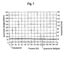
- Fig. 7 shows the damping characteristic of the damping device 10 during driving at an amplitude of +/- 0.05 mm and a channel diameter (damping channel 19 and bypass channel 20) of 15 mm. It can be seen that the loss angle due to the opened bypass channel 20 is approximately zero and the dynamic stiffness assumes a value of 60 N / mm. Consequently, the damper 10 is in this Switching state is only a very soft transmission path and no droning is perceptible to the driver while driving.
- the damping depending on the operating state of the motor vehicle engine 47 by means of the switchable valve 22 can be changed.
- the bypass channel 20 is closed, so that a damping takes place.
- the bypass channel is open, so that no droning occurs. Consequently, the damping device 10 according to the invention increases ride comfort.
Landscapes
- Engineering & Computer Science (AREA)
- General Engineering & Computer Science (AREA)
- Mechanical Engineering (AREA)
- Physics & Mathematics (AREA)
- Acoustics & Sound (AREA)
- Aviation & Aerospace Engineering (AREA)
- Arrangement Or Mounting Of Propulsion Units For Vehicles (AREA)
- Combined Devices Of Dampers And Springs (AREA)
- Vibration Prevention Devices (AREA)
Description
- Die vorliegende Erfindung betrifft eine Dämpfungseinrichtung zur Dämpfung von An- und Abstellschlägen eines Kraftfahrzeugmotors, mit einer ersten und zweiten Kammer, die mit einem Dämpfungsmedium gefüllt sind und durch eine Zwischenplatte getrennt sind, wobei die Kammern jeweils durch einen Faltenbalg und durch eine Stirnplatte begrenzt sind, wobei in der Zwischenplatte ein die Kammern verbindender Dämpfungskanal eingebracht ist, wobei beide Kammern mit wenigstens einem Bypasskanal verbunden sind, und wobei der Bypasskanal mittels eines schaltbaren Ventils freigebbar oder verschließbar ist. Des Weiteren bezieht sich die Erfindung auf ein Dämpfungssystem mit einer derartigen Dämpfungseinrichtung.
- Um den Kraftstoffverbrauch zu reduzieren, verfügen moderne Kraftfahrzeuge häufig über ein so genanntes Start- und Stopp-System, das den Kraftfahrzeugmotor abschaltet, wenn dieser nicht benötigt wird, wie beispielsweise bei einem Ampelstopp. Die Funktionsweise dieses Systems kann wie folgt anhand eines Ampelstopps beschrieben werden. Hält der Fahrer an einer Ampel an und schaltet in den Leerlauf, so schaltet sich der Kraftfahrzeugmotor beim Lösen der Kupplung aus. Zum Losfahren betätigt der Fahrer die Kupplung und der Motor wird wieder gestartet. Bei den zuvor genannten An- und Abstellvorgängen kommt es zu starken Schlägen des Motors, die in der Fahrgastzelle zu spüren sind und folglich den Fahrkomfort einschränken.
- Aus der
US 6,082,508 geht eine Dämpfungseinrichtung der eingangs genanten Art hervor, die für den Einsatz in einem Satellit vorgesehen ist. Die Dämpfungseinrichtung weist eine Zwischenplatte und zwei sich in Längsrichtung von der Zwischenplatte jeweils in die entgegengesetzte Richtung wegerstreckende Faltenbalge auf. An ihren Stirnseiten sind die Faltenbalge mittels einer Platte derart verschlossen, dass zwei Arbeitskammern gebildet werden. Beide Kammern sind über einen Kanal in der Zwischenplatte miteinander verbunden. Als Arbeitsmedium wird ein kompressibles Fluid, insbesondere Luft, verwendet. Zur Dämpfung fließt das kompressible Fluid über den Dämpfungskanal von einer Kammer zur anderen Kammer, wobei der Dämpfungseffekt infolge der im Kanal auftretenden Reibung erzeugt wird. - Aus
FR 1.112.259 A - In
US 5,062,497 A geht eine Dämpfungseinrichtung hervor, die zwei durch eine Zwischenplatte getrennte Arbeitskammern aufweist, wobei die Arbeitskammern jeweils durch eine Zwischenplatte und einen Faltenbalg begrenzt sind. Die beiden Kammern sind durch einen Flüssigkeitskanal, der mittels eines Ventils freigebbar und verschließbar ist, verbunden. - Aus
US 4,854,555 A geht eine Dämpfungseinrichtung hervor, die zwei Kammern aufweist, die durch eine Zwischenplatte voneinander getrennt sind und jeweils durch ein Außengehäuse, einen Kolben und eine Membran begrenzt sind. In die Zwischenplatte ist ein Dämpfungskanal eingebracht. Des Weiteren ist in die Zwischenplatte eine Öffnung vorgesehen durch die eine Kolbenstange geführt ist, wobei zwischen der Öffnung und der Kolbenstange ein O-Ring angeordnet ist. Durch Weglassen des O-Rings wird eine Art Bypasskanal erzeugt. Die Dämpfungscharakteristik des Dämpfungskanals kann mittels einer rotierbaren Platte eingestellt werden. - In der
US 4,516,545 ist eine Dämpfungseinrichtung zur Dämpfung der Bewegungen eines Kraftfahrzeugmotors offenbart. Die Dämpfungseinrichtung weist zwei mit Öl gefüllte Kammern auf, die durch eine Zwischenplatte voneinander getrennt sind und jeweils durch eine elastische Umhausung begrenzt sind. In der Zwischenplatte sind zwei mit unterschiedlichen Querschnitten versehene Kanäle eingebracht, die die beiden Kammern miteinander verbinden. Der Kanal mit größeren Querschnitt ist mittels eines Drehventils öffenbar und schließbar. - Der Erfindung liegt die Aufgabe zugrunde, eine Dämpfungseinrichtung zu schaffen, die die An- und Abstellschläge eines Kraftfahrzeugmotors dämpft und im Fahrbetrieb frei von einer Dämpfungswirkung ist.
- Zur Lösung dieser Aufgabe wird bei einer Dämpfungseinrichtung der eingangs genannten Art vorgeschlagen, dass der Bypasskanal die beiden Kammern mit der Umgebung verbindet, dass der Schaltzustand des Ventils vom Betriebszustand des Kraftfahrzeugmotors abhängt und dass der Bypasskanal während des An- und Abstellvorgangs des Kraftfahrzeugmotors geschlossen ist und im Fahrbetrieb geöffnet ist.
- Vorteilhafte Ausgestaltungen sind Gegenstand der Unteransprüche.
- Bei der erfindungsgemäßen Dämpfungseinrichtung kann die Dämpfung abhängig vom Betriebszustand des Motors mittels des schaltbaren Ventils verändert werden. In einer ersten Schaltstellung ist der Bypasskanal verschlossen, so dass die verdrängte Luft über den zwischen den Kammern angeordneten Dämpfungskanal strömt. Hierdurch werden insbesondere die beim An- und Abstellen auftretenden Schläge gedämpft. In einer zweiten Schaltstellung ist der Bypasskanal geöffnet, so dass die verdrängte Luft über den Bypasskanal und nicht über den Dämpfungskanal strömt. Insbesondere infolge des größeren Querschnitts des Bypasskanals wird die Luft bei geöffnetem Bypasskanal über diesen geleitet, so dass im Fahrbetrieb keine Dämpfung erfolgt. Somit liegt in dieser Schaltstellung keine Dämpfung vor. Aufgrund der niedrigen Steifigkeit der Faltenbalge tritt auch bei hohen Frequenzen kein Dröhnen auf. Somit erhöht die erfindungsgemäße Dämpfungseinrichtung den Fahrkomfort. Da der Bypasskanal die beiden Kammern mit der Umgebung verbindet, ermöglicht der Bypasskanal ein Ausströmen des Dämpfungsmediums aus den beiden Kammern in die Umgebung, wodurch der Dämpfungskanal überbrückt wird.
- In einer vorteilhaften Ausgestaltung weist der Bypasskanal einen größeren Querschnitt als der Dämpfungskanal auf. Hierdurch wird die Luft bei geöffnetem Bypasskanal über diesen geleitet, so dass im Fahrbetrieb keine Dämpfung erfolgt.
- Vorteilhaft ist der Bypasskanal in der Zwischenplatte eingebracht.
- Bei einer weiteren Ausgestaltung verbindet der Bypasskanal die beiden Kammern miteinander.
- Bei einer weiteren Ausgestaltung ist ein erster Bypasskanal in die erste Stirnplatte zum Verbinden der ersten Kammer mit der Umgebung eingebracht und ein zweiter Bypasskanal ist in die zweite Stirnplatte zum Verbinden der zweiten Kammer mit der Umgebung eingebracht.
- Vorteilhaft ist das Ventil als mehrstufig oder stufenlos verstellbares Ventil ausgebildet. Somit kann der Querschnitt des Bypasskanals vorteilhaft an die jeweilige Nickfrequenz des Kraftfahrzeugmotors angepasst werden.
- Das Ventil ist vorteilhaft mittels Vakuum oder elektromagnetisch schaltbar. Derartige Ventile sind einerseits kostengünstig und weisen andererseits eine hohe Zuverlässigkeit auf.
- In einer weiteren vorteilhaften Ausgestaltung wird als Dämpfungsmedium Luft verwendet. Luftlager sind im Vergleich zu hydraulischen Lagern kostengünstiger, da eine Befüllung mit Dämpfungsflüssigkeit entfällt.
- Vorteilhaft sind die Faltenbälge koaxial zum Dämpfungskanal angeordnet.
- Vorteilhaft ist die erste Stirnplatte an der Stirnseite des ersten Faltenbalges angebracht und die zweite Stirnplatte ist an der Stirnseite des zweiten Faltenbalges angebracht.
- Die Faltenbälge weisen vorteilhaft eine Länge von 5 mm bis 20 mm, vorzugsweise von 5 mm bis 10 mm, auf. Des Weiteren weisen die Faltenbälge vorteilhaft einen äußeren Durchmesser von 70 mm bis 100 mm, vorzugsweise von 80 mm bis 90 mm, auf. Aufgrund der Abmaße der Faltenbälge wird ein vorteilhaftes kleines Kammervolumen sowie eine große Pumpfläche zur Verfügung gestellt, so dass ein wirksamer Dämpfungseffekt erzielt werden kann.
- Vorteilhaft sind die Faltenbälge aus einem thermoplastischen Elastomer (TPE) oder einem Thermoplast (TP) hergestellt. Somit haben die Faltenbälge eine hohe Lebensdauer bei gleichzeitig konstanten Werkstoffeigenschaften.
- Weiterhin betrifft die vorliegende Erfindung ein Dämpfungssystem zur Dämpfung von An- und Abstellschlägen eines Kraftfahrzeugmotors, das eine erfindungsgemäße Dämpfungseinrichtung und eine Steuereinrichtung zum Steuern des schaltbaren Ventils der Dämpfungseinrichtung abhängig vom Betriebszustand des Kraftfahrzeugmotors aufweist. Das schaltbare Ventil der Dämpfungseinrichtung wird über die Steuereinrichtung abhängig vom Betriebszustand des Kraftfahrzeugmotors angesteuert.
- Vorteilhaft ist das schaltbare Ventil während des An- und Abstellvorgangs des Kraftfahrzeugmotors geschlossen und im Fahrbetrieb geöffnet. Somit erfolgt vorteilhaft während des An- und Abstellens des Kraftfahrzeugmotors eine Dämpfung und im Fahrbetrieb erfolgt keine Dämpfung.
- Nachfolgend wird die Erfindung anhand von Ausführungsbeispielen näher erläutert, die in den Zeichnungen schematisch dargestellt sind. Hierbei zeigen:
-
Fig. 1 einen Horizontalschnitt durch eine erste Ausführungsform der erfindungsgemäßen Dämpfungseinrichtung; -
Fig. 2 einen Horizontalschnitt durch die erfindungsgemäße Dämpfungseinrichtung mit daran angebrachten Verbindungselementen; -
Fig. 3 eine schematische Darstellung des erfindungsgemäßen Dämpfungssystems; -
Fig. 4 eine nicht erfindungsgemäße Dämpfungseinrichtung; -
Fig. 5 einen Horizontalschnitt einer zweiten Ausführungsform der erfindungsgemäßen Dämpfungseinrichtung; -
Fig. 6 eine graphische Darstellung der Dämpfungs- und Steifigkeitscharakteristik der erfindungsgemäßen Dämpfungseinrichtung während des An- und Abstellvorgangs und -
Fig. 7 eine graphische Darstellung der Dämpfungs- und Steifigkeitscharakteristik der erfindungsgemäßen Dämpfungseinrichtung während des Fahrbetriebs. -
Fig. 1 zeigt eine Dämpfungseinrichtung 10, die zur Dämpfung von An- und Abstellschlägen eines quer eingebauten Kraftfahrzeugmotors 47 vorgesehen ist, der über ein Start-Stopp-System verfügt. Die Dämpfungseinrichtung 10 weist eine Zwischenplatte 11, einen ersten Faltenbalg 12, eine erste Stirnplatte 13, einen zweiten Faltenbalg 15 und eine zweite Stirnplatte 16 auf. Die Faltenbälge 12, 15 sind an einem ersten Endbereich mit der Zwischenplatte 11 verbunden. An einem zweiten Endbereich ist die Stirnplatte 13, 16 vorgesehen. - Die Zwischenplatte 11, der erste Faltenbalg 12 und die erste Stirnplatte 13 bilden eine erste Arbeitskammer 14. Die Zwischenplatte 11, der zweite Faltenbalg 15 und die zweite Stirnplatte 16 bilden eine zweite Arbeitskammer 17. Beide Arbeitskammern 14, 17 sind über einen in die Zwischenplatte 11 eingebrachten Dämpfungskanal 19 miteinander verbunden. Innerhalb der Arbeitskammern 14, 17 befindet sich ein Dämpfungsmedium 18, insbesondere Luft. Des Weiteren ist in die Zwischenplatte 11 ein Bypasskanal 20 eingebracht, der die erste Kammer 14 und die zweite Kammer 17 mit der Umbebung verbindet. Der Bypasskanal 20 weist einen größeren Durchmesser als der Dämpfungskanal 19 auf.
- Die Zwischenplatte 11 besteht aus einem metallischen Werkstoff, kann aber auch aus einem Kunststoff hergestellt sein. Die Faltenbälge 12, 15 bestehen aus einem thermoplastischen Elastomer (TPE) oder einem Thermoplast (TP) und haben eine Länge von 5 mm bis 20 mm und einen äußeren Durchmesser von 70 mm bis 100 mm. Die Stirnplatten 13, 16 bestehen ebenfalls aus einem metallischen Werkstoff, können aber auch aus einem Kunststoff bestehen.
- Zur Bildung der Kammern 14, 17 erstrecken sich die Faltenbälge 12, 15 weg von der Zwischenplatte koaxial zu dem Dämpfungskanal 19, wobei sich die Faltenbälge 12, 15 in entgegengesetzter Richtung erstrecken. Die offenen Stirnseiten der Faltenbälge 12, 15 sind jeweils mit einer Stirnplatte 13, 16 verschlossen. Zur Verbindung der Faltenbälge 12, 15 mit der Zwischenplatte 11 sowie mit den jeweiligen Stirnplatten 13, 16 werden allgemein bekannte Verbindungsverfahren, wie beispielsweise Kleben, eingesetzt.
- Gemäß
Fig. 1 ist an der Zwischenplatte 11 der Dämpfungseinrichtung 10 ein schaltbares Ventil 22 angebracht. Das schaltbare Ventil 22 weist ein Stellglied 23 auf, das in bekannter Weise mittels Vakuum oder elektromagnetisch schaltbar ist. Das Stellglied 23 öffnet oder schließt den Bypasskanal 20, wie dies mit Hilfe des inFig. 1 gezeigten Doppelpfeils 24 dargestellt ist. Das Ventil kann auch mehrstufig oder stufenlos verstellbar ausgebildet sein. Hierdurch ist es möglich, den Kanalquerschnitt des Bypasskanals 20 stufig oder stufenlos zwischen Null und dem Maximalquerschnitt zu verstellen. Somit lässt sich die Dämpfungseinrichtung 10 optimal an die Nickfrequenz des Kraftfahrzeugmotors 47 anpassen. - In
Fig. 1 ist die Dämpfungseinrichtung in einer ersten Schaltstellung gezeigt, in der der Bypasskanal 20 durch das Stellglied 23 geschlossen ist. Dies entspricht dem Schaltzustand während des An- und Abstellens des Kraftfahrzeugmotors 47. - In
Fig. 2 ist die Dämpfungseinrichtung 10 in einer zweiten Schaltstellung, in der der Bypasskanal 20 geöffnet ist, gezeigt. In dieser Schaltstellung strömt die verdrängte Luft über den Bypasskanal 20 in die Umgebung, so dass keine Dämpfung erfolgt. - Des Weiteren ist in
Fig. 2 eine Befestigungseinrichtung 30 zur Befestigung der Dämpfungseinrichtung 10 an dem Kraftfahrzeugmotor 47 und der Fahrzeugkarosserie dargestellt. Die Befestigungseinrichtung 30 weist ein motorseitiges Verbindungselement 31, das die Zwischenplatte 11 der Dämpfungseinrichtung 10 mit dem Kraftfahrzeugmotor 47 verbindet, und ein radhausseitiges Verbindungselement 31 zur Verbindung der Dämpfungseinrichtung 10 mit der Fahrzeugkarosserie auf. Das radhausseitige Verbindungselement 32 ist jeweils mit einer der Stirnplatten 13, 16 verbunden, so dass es die Dämpfungseinrichtung 10 umgreift. - In
Fig. 3 ist schematisch das Dämpfungssystem 40 dargestellt. Das Dämpfungssystem 40 weist die Dämpfungseinrichtung 10, eine Steuereinrichtung 41, eine erste Übertragungseinrichtung 42 zum Verbinden der Steuereinrichtung 41 mit dem schaltbaren Ventil 22 und eine zweite Übertragungseinrichtung 46 zum Verbinden des Kraftfahrzeugmotors 47 mit der Steuereinrichtung 41 auf. Zur Einbindung der Dämpfungseinrichtung 10 in das Dämpfungssystem 40 ist die Dämpfungseinrichtung 10 über das motorseitige Verbindungselement 31 mit einem Motorhalter 45, der mit einem nicht näher definierten Motorlager 44 verbunden ist, und über das radhausseitige Verbindungselement 32 mit einem Radhaus 43 verbunden. - Die Funktionsweise des Dämpfungssystems 40 wird nachfolgend beschrieben. Bei einem An- und Abstellvorgang des quer eingebauten Kraftfahrzeugmotors 47 führt dieser Nickbewegungen um die Fahrzeugquerachse aus. Mittels der zweiten Übertragungseinrichtung 46 wird die Information, dass es sich hierbei um einen An- und Abstellvorgang handelt, an die Steuereinrichtung 41 weitergeleitet. In der Steuereinrichtung 41 wird die Information derart verarbeitet, dass über die erste Übertragungseinrichtung 42 das schaltbare Ventil 22 derart angesteuert wird, dass das Stellglied 23 den Bypasskanal 20 verschließt. Folglich befindet sich die Dämpfungseinrichtung 10 in dem in
Fig.1 dargestellten Zustand. Somit werden die Nickbewegungen des Kraftfahrzeugmotors 40 auf den Halter 45 übertragen und diese wiederum auf das motorseitige Verbindungselement 31, so dass sich die Zwischenplatte 11 in Fahrzeuglängsrichtung bewegt, wie dies inFig. 2 mit dem Doppelpfeil 25 dargestellt ist. Durch die Bewegung der Zwischenplatte 11 strömt abwechselnd das Dämpfungsfluid 18 über den Dämpfungskanal 19 von einer Kammer in die andere Kammer 14, 17. Aufgrund des geringen Querschnitts des Dämpfungskanals 19 wird ein Reibungseffekt erzeugt, der zu einer Dämpfungswirkung führt. - Im Fahrbetrieb wird mit Hilfe der ersten Übertragungseinrichtung 42 das schaltbare Ventil 22 derart ansteuert, dass das Stellglied 23 den Bypasskanal 20 freigibt, wie dies in
Fig. 2 dargestellt ist. Somit werden die während des Fahrbetriebs auftretenden Nickbewegungen des Kraftfahrzeugmotors 47 nicht gedämpft. Grund hierfür ist einerseits, dass das in den beiden Arbeitskammern 14,17 vorhandene Dämpfungsmedium 18 über den Bypasskanal 20 an die Umgebung abgeführt wird, und andererseits, dass die Faltenbälge 12, 15 eine niedrige statische Grundsteifigkeit aufweisen. Somit wird im Fahrbetrieb einem Dröhnen entgegengewirkt und zugleich wird der Fahrkomfort erhöht. -
Fig. 4 zeigt eine nicht erfindungsgemäße Ausführungsform der Dämpfungseinrichtung 10, die sich von der Dämpfungseinrichtung 10 gemäß denFig. 1 und 2 dadurch unterscheidet, dass der Bypasskanal 20 die Kammern 14, 17 miteinander verbindet, wobei der Bypasskanal 20 mittels des Stellglieds 23 freigebbar oder verschließbar ist. Zur Erzielung einer Dämpfungswirkung wird der Bypasskanal 20 mit Hilfe des Stellglieds 23 verschlossen. Um im Fahrbetrieb keine Dämpfungswirkung zu erzielen, wird das Stellglied 23 in eine Position verfahren, die den Bypasskanal 20 freigibt. -
Fig. 5 zeigt eine zweite Ausführungsform der erfindungsgemäßen Dämpfungseinrichtung 10. Die Dämpfungseinrichtung 10 gemäß der zweiten Ausführungsform unterscheidet sich von der ersten Ausführungsform darin, dass jeweils ein Bypasskanal 50, 53 in die Stirnplatte 13, 16 eingebracht ist, wobei jeder Bypasskanal 50, 53 über jeweils ein schaltbares Ventil 51, 54 freigebbar und verschließbar ist. In der ersten Stirnplatte 13 ist ein erster Bypasskanal 50 eingebracht, wobei an der ersten Stirnplatte 13 das erste schaltbare Ventil 51 angebracht ist, dessen erstes Stellglied 52 den ersten Bypasskanal 50 verschließt oder öffnet. An der zweiten Stirnplatte 16 ist ein zweiter Bypasskanal 53 eingebracht, der mittels eines zweiten Stellglieds 55 des zweiten schaltbaren Ventils 54 freigebbar oder verschließbar ist. Sowohl das erste schaltbare Ventil 51 als auch das zweite schaltbare Ventil 54 sind über die Übertragungseinrichtung 42 mit der Steuereinrichtung 41 verbunden. Zur Erzielung einer Dämpfungswirkung wird sowohl der erste Bypasskanal 50 als auch der zweite Bypasskanal 53 mit Hilfe der Stellglieder 52, 55 verschlossen. Um keinen Dämpfungseffekt zu erzielen, werden beide Bypasskanäle 50, 53 freigegeben. - Die Funktionsweise der beiden Ausführungsformen sowie deren Befestigungseinrichtung 30 entspricht denen der ersten Ausführungsform, so dass auf eine detaillierte Beschreibung im Folgenden verzichtet wird.
- In den
Fig. 6 und7 ist die Dämpfungs- und Steifigkeitscharakteristik der Dämpfungseinrichtung 10 in verschiedenen Schaltstellungen des Ventils 22 gezeigt. Hierbei ist der Verlauf der dynamischen Steifigkeit und der Verlauf des Verlustwinkels dargestellt. - In
Fig. 6 ist die Dämpfungs- und Steifigkeitscharakteristik der Dämpfungseinrichtung 10 während eines An- und Abstellvorgangs eines Kraftfahrzeugmotors 47 bei einer Amplitude von +/- 4 mm und einem Kanaldurchmesser von 1,5 mm dargestellt. Dieser Kanaldurchmesser entspricht dem Durchmesser des Dämpfungskanals 19. Hierbei ist ersichtlich, dass der Verlustwinkel sein Maximum bei einer Frequenz von ungefähr 6 Hz hat und mit zunehmender Frequenz sinkt. Somit liegt bei großen Amplituden und niedrigen Frequenzen eine hohe Dämpfung vor. Die dynamische Steifigkeit ist im Gegensatz zu dem Verlustwinkel bei niedrigen Frequenzen und großen Amplituden gering und nimmt mit steigender Frequenz zu. Dies entspricht einer Verhärtung des Lagers bei hohen Frequenzen. -
Fig. 7 zeigt die Dämpfungscharakteristik der Dämpfungseinrichtung 10 während des Fahrbetriebs bei einer Amplitude von +/- 0,05 mm und einem Kanaldurchmesser (Dämpfungskanal 19 und Bypasskanal 20) von 15 mm. Hieraus ist ersichtlich, dass der Verlustwinkel aufgrund des geöffneten Bypasskanals 20 annähernd Null ist und die dynamische Steifigkeit einen Wert von 60 N/mm annimmt. Folglich stellt die Dämpfungseinrichtung 10 in diesem Schaltzustand nur einen sehr weichen Übertragungsweg dar und für den Fahrer ist im Fahrbetrieb keinerlei Dröhnen wahrnehmbar. - Bei der vorstehend beschriebenen Dämpfungseinrichtung 10 kann die Dämpfung abhängig vom Betriebszustand des Kraftfahrzeugmotors 47 mit Hilfe des schaltbaren Ventils 22 verändert werden. Während des An- und Abstellvorgangs ist der Bypasskanal 20 geschlossen, so dass eine Dämpfung erfolgt. Im Fahrbetrieb ist der Bypasskanal geöffnet, so dass kein Dröhnen auftritt. Folglich erhöht die erfindungsgemäße Dämpfungseinrichtung 10 den Fahrkomfort.
Bezugszeichenliste 10 Dämpfungseinrichtung 46 zweite Übertragungseinrichtung 11 Zwischenplatte 12 erster Faltenbalg 47 Kraftfahrzeugmotor 13 erste Stirnplatte 14 erste Arbeitskammer 50 erster Bypasskanal 15 zweiter Faltenbalg 51 erstes schaltbares Ventil 16 zweite Stirnplatte 52 erstes Stellglied 17 zweite Arbeitskammer 53 zweiter Bypasskanal 18 Dämpfungsmedium 54 zweites schaltbares Ventil 19 Dämpfungskanal 55 zweites Stellglied 20 Bypasskanal 22 schaltbares Ventil 23 Stellglied 24 Doppelpfeil 25 Doppelpfeil 30 Befestigungseinrichtung 31 motorseitiges Verbindungselement 32 radhausseitiges Verbindungselement 40 Dämpfungssystem 41 Steuereinrichtung 42 erste Übertragungseinrichtung 43 Radhaus 44 Motorlager 45 Halter
Claims (13)
- Dämpfungseinrichtung (10) zur Dämpfung von An- und Abstellschlägen eines Kraftfahrzeugmotors (47), mit einer ersten und zweiten Kammer (14, 17), die mit einem Dämpfungsmedium (18) gefüllt sind und durch eine Zwischenplatte (11) getrennt sind, wobei die Kammern (14, 17) jeweils durch einen Faltenbalg (12, 15) und durch eine Stirnplatte (13, 16) begrenzt sind, wobei in der Zwischenplatte (11) ein die Kammern (14, 17) verbindender Dämpfungskanal (19) eingebracht ist, wobei beide Kammern (14, 17) mit wenigstens einem Bypasskanal (20) verbunden sind, und wobei der Bypasskanal (20) mittels eines schaltbaren Ventils (22, 51, 54) freigebbar oder verschließbar ist, dadurch gekennzeichnet dass der Bypasskanal (20) die beiden Kammern (14, 17) mit der Umgebung verbindet, dass der Schaltzustand des Ventils (22, 51, 54) vom Betriebszustand des Kraftfahrzeugmotors (47) abhängt und dass der Bypasskanal (19) während des An- und Abstellvorgangs des Kraftfahrzeugmotors (47) geschlossen und im Fahrbetrieb geöffnet ist.
- Dämpfungseinrichtung nach Anspruch 1, dadurch gekennzeichnet, dass der Bypasskanal (20) einen größeren Querschnitt als der Dämpfungskanal (19) aufweist.
- Dämpfungseinrichtung (10) nach Anspruch 1 oder 2, dadurch gekennzeichnet, dass der Bypasskanal (20) in der Zwischenplatte (11) eingebracht ist.
- Dämpfungseinrichtung (10) nach Anspruch 1 oder 2, dadurch gekennzeichnet, dass ein erster Bypasskanal (50) in die erste Stirnplatten (13) zum Verbinden der ersten Kammer (14) mit der Umgebung eingebracht ist und dass ein zweiter Bypasskanal (53) in die zweite Stirnplatte (16) zum Verbinden der zweiten Kammer (17) mit der Umgebung eingebracht ist.
- Dämpfungseinrichtung nach einem der Ansprüche 1 bis 4, dadurch gekennzeichnet, dass das Ventil (22, 51, 54) als mehrstufig oder stufenlos verstellbares Ventil ausgebildet ist.
- Dämpfungseinrichtung (10) nach einem der Ansprüche 1 bis 5, dadurch gekennzeichnet, dass das Ventil (22, 51, 54) mittels Vakuum oder elektromagnetisch schaltbar ist.
- Dämpfungseinrichtung (10) nach einem der Ansprüche 1 bis 6, dadurch gekennzeichnet, dass als Dämpfungsmedium (18) Luft verwendet wird.
- Dämpfungseinrichtung (10) nach einem der Ansprüche 1 bis 7, dadurch gekennzeichnet, dass die Faltenbälge (12, 15) koaxial zum Dämpfungskanal (19) angeordnet sind.
- Dämpfungseinrichtung (10) nach einem der Ansprüche 1 bis 8, dadurch gekennzeichnet, dass die erste Stirnplatte (13) an der Stirnseite des ersten Faltenbalgs (12) angebracht ist und dass die zweite Stirnplatte (16) an der Stirnseite des zweiten Faltenbalgs (15) angebracht ist.
- Dämpfungseinrichtung (10) nach einem der Ansprüche 1 bis 9, dadurch gekennzeichnet, dass die Faltenbälge (12, 15) eine Länge von 5 mm bis 20 mm, vorzugsweise von 5 mm bis 10 mm, aufweisen.
- Dämpfungseinrichtung (10) nach einem der Ansprüche 1 bis 10, dadurch gekennzeichnet, dass die Faltenbälge (12, 15) einen äußeren Durchmesser von 70 mm bis 100 mm, vorzugsweise von 80 mm bis 90 mm, aufweisen.
- Dämpfungseinrichtung (10) nach einem der Ansprüche 1 bis 11, dadurch gekennzeichnet, dass die Faltenbälge (12,15) aus einem thermoplastischen Elastomer (TPE) oder einem Thermoplast (TP) hergestellt sind.
- Dämpfungssystem (40) zur Dämpfung von An- und Abstellschlägen eines Kraftfahrzeugmotors (47) mit einer Dämpfungseinrichtung (10) nach einem der voranstehenden Ansprüche 1 bis 12 und einer Steuereinrichtung (41) zum Steuern des schaltbaren Ventils (22, 51, 54) der Dämpfungseinrichtung (10) abhängig vom Betriebszustand des Kraftfahrzeugmotors (47).
Priority Applications (1)
| Application Number | Priority Date | Filing Date | Title |
|---|---|---|---|
| PL10737822T PL2456998T3 (pl) | 2009-07-24 | 2010-07-12 | Urządzenie tłumiące |
Applications Claiming Priority (2)
| Application Number | Priority Date | Filing Date | Title |
|---|---|---|---|
| DE102009034677A DE102009034677B4 (de) | 2009-07-24 | 2009-07-24 | Dämpfungseinrichtung |
| PCT/EP2010/060000 WO2011009752A1 (de) | 2009-07-24 | 2010-07-12 | Dämpfungseinrichtung |
Publications (2)
| Publication Number | Publication Date |
|---|---|
| EP2456998A1 EP2456998A1 (de) | 2012-05-30 |
| EP2456998B1 true EP2456998B1 (de) | 2015-09-09 |
Family
ID=42829802
Family Applications (1)
| Application Number | Title | Priority Date | Filing Date |
|---|---|---|---|
| EP10737822.6A Not-in-force EP2456998B1 (de) | 2009-07-24 | 2010-07-12 | Dämpfungseinrichtung |
Country Status (7)
| Country | Link |
|---|---|
| US (1) | US20120152670A1 (de) |
| EP (1) | EP2456998B1 (de) |
| JP (1) | JP2013500436A (de) |
| KR (1) | KR101367605B1 (de) |
| DE (1) | DE102009034677B4 (de) |
| PL (1) | PL2456998T3 (de) |
| WO (1) | WO2011009752A1 (de) |
Families Citing this family (4)
| Publication number | Priority date | Publication date | Assignee | Title |
|---|---|---|---|---|
| DE102016113971B4 (de) | 2016-07-28 | 2019-01-31 | Vibracoustic Gmbh | Motorabstützungsvorrichtung |
| DE102016223707A1 (de) * | 2016-11-29 | 2018-05-30 | Audi Ag | Lageranordnung für ein Fahrzeug sowie Verfahren zur Steuerung einer solchen Lageranordnung |
| JP6900908B2 (ja) * | 2018-01-09 | 2021-07-07 | トヨタ自動車株式会社 | 車両用制御装置 |
| JP7027920B2 (ja) * | 2018-02-01 | 2022-03-02 | トヨタ自動車株式会社 | ハイブリッド車両の制御装置 |
Citations (1)
| Publication number | Priority date | Publication date | Assignee | Title |
|---|---|---|---|---|
| US4516545A (en) * | 1983-04-15 | 1985-05-14 | Mitsubishi Jidosha Kogyo Kabushiki Kaisha | Apparatus for controlling the rolling of an engine |
Family Cites Families (33)
| Publication number | Priority date | Publication date | Assignee | Title |
|---|---|---|---|---|
| FR1112259A (fr) | 1954-10-06 | 1956-03-12 | Suspension à membranes et air comprimé | |
| US3141523A (en) * | 1962-05-10 | 1964-07-21 | Robert J Dickie | Vibration damper |
| US3243154A (en) * | 1964-04-03 | 1966-03-29 | Hugh L Dryden | Vibration damping system |
| US3459395A (en) * | 1967-08-16 | 1969-08-05 | Ambac Ind | Shock isolating means |
| US3752270A (en) * | 1971-12-29 | 1973-08-14 | J Valdespino | Shock absorber structure including flexible bladder means |
| DE2406835A1 (de) * | 1974-02-13 | 1975-08-14 | Gold Henning Dipl Ing | Federungs- und daempfungsvorrichtung, insbesondere fuer fahrzeuge |
| DE2736188C3 (de) * | 1977-08-11 | 1981-05-14 | Audi Nsu Auto Union Ag, 7107 Neckarsulm | Gummilager mit hydraulischer Dämpfung |
| JPS5476778A (en) * | 1977-11-30 | 1979-06-19 | Nihon Plast Co Ltd | Bellows type double acting actuator |
| JPS57147925A (en) * | 1981-03-11 | 1982-09-13 | Honda Motor Co Ltd | Engine suspension device |
| DE3436664A1 (de) | 1983-10-07 | 1985-05-02 | Bridgestone Corp., Tokio/Tokyo | Membran-luftfeder |
| FR2553536B1 (fr) * | 1983-10-13 | 1985-12-27 | Aerospatiale | Procede et dispositif pour reguler le mouvement d'un organe par mise en oeuvre d'un ecoulement fluide |
| US4572488A (en) * | 1983-12-08 | 1986-02-25 | The United States Of America As Represented By The Secretary Of The Air Force | Low temperature rate controller |
| DE3421135A1 (de) * | 1984-06-07 | 1985-12-12 | Audi AG, 8070 Ingolstadt | Hydraulisches motorlager |
| JPS6448635U (de) * | 1987-09-19 | 1989-03-27 | ||
| GB8730005D0 (en) * | 1987-12-23 | 1988-02-03 | Avon Ind Polymers | Hydraulically damped mounting device |
| JP2523445Y2 (ja) | 1988-07-01 | 1997-01-22 | 日産自動車株式会社 | エンジンマウントバネ定数切換制御装置 |
| DE3827329A1 (de) * | 1988-08-09 | 1990-02-15 | Mannesmann Ag | Drehmomentabstuetzung fuer auf wellenzapfen reitende antriebe, insbesondere fuer konverterkippantriebe |
| JPH03234938A (ja) * | 1989-08-25 | 1991-10-18 | Bridgestone Corp | 振動減衰装置 |
| FR2675871B1 (fr) * | 1991-04-29 | 1995-02-17 | Hutchinson | Perfectionnements apportes aux dispositifs antivibratoires hydrauliques. |
| US5332070A (en) * | 1993-04-21 | 1994-07-26 | Honeywell Inc. | Three parameter viscous damper and isolator |
| DE4401770A1 (de) * | 1994-01-24 | 1995-08-03 | Fichtel & Sachs Ag | Selbstpumpendes Ferderbein mit Niveauregelung |
| US5597147A (en) * | 1994-03-08 | 1997-01-28 | Transuport Corporation | Articulation mechanism and a universal arm means applying the mechanism |
| JPH0925986A (ja) * | 1995-07-14 | 1997-01-28 | Nok Megurasutikku Kk | 液体封入式マウント |
| JP3425726B2 (ja) * | 1996-07-25 | 2003-07-14 | 三菱ふそうトラック・バス株式会社 | エンジンの防振支持装置 |
| US6082508A (en) | 1997-04-23 | 2000-07-04 | Honeywell International Inc. | Pneumatic damping strut |
| US5979882A (en) * | 1997-11-22 | 1999-11-09 | Honeywell Inc. | Direct fluid shear damper |
| HUP0101274A3 (en) * | 1998-12-03 | 2002-02-28 | Phoenix Ag | Pneumatic suspension system |
| JP2001277865A (ja) * | 2000-03-30 | 2001-10-10 | Isuzu Motors Ltd | エンジン支持装置 |
| US6561500B2 (en) * | 2001-03-07 | 2003-05-13 | The Goodyear Tire & Rubber Company | Hydro-damped air spring |
| DE10223405B4 (de) * | 2002-05-25 | 2007-01-11 | Daimlerchrysler Ag | Luftfedersystem für ein Kraftfahrzeug |
| DE102005060581B4 (de) * | 2005-12-17 | 2015-09-24 | Continental Teves Ag & Co. Ohg | Luftfeder- und Dämpfereinheit mit vorgesteuertem Hauptventil |
| JP2007253251A (ja) * | 2006-03-20 | 2007-10-04 | Max Co Ltd | 打ち込み工具のフック装置 |
| FR2926122A1 (fr) * | 2008-01-03 | 2009-07-10 | Hutchinson Sa | Amortisseur de vibrations notamment pour structure aerospatiale |
-
2009
- 2009-07-24 DE DE102009034677A patent/DE102009034677B4/de not_active Expired - Fee Related
-
2010
- 2010-07-12 JP JP2012520996A patent/JP2013500436A/ja active Pending
- 2010-07-12 PL PL10737822T patent/PL2456998T3/pl unknown
- 2010-07-12 US US13/386,821 patent/US20120152670A1/en not_active Abandoned
- 2010-07-12 EP EP10737822.6A patent/EP2456998B1/de not_active Not-in-force
- 2010-07-12 KR KR1020127004518A patent/KR101367605B1/ko not_active Expired - Fee Related
- 2010-07-12 WO PCT/EP2010/060000 patent/WO2011009752A1/de not_active Ceased
Patent Citations (1)
| Publication number | Priority date | Publication date | Assignee | Title |
|---|---|---|---|---|
| US4516545A (en) * | 1983-04-15 | 1985-05-14 | Mitsubishi Jidosha Kogyo Kabushiki Kaisha | Apparatus for controlling the rolling of an engine |
Also Published As
| Publication number | Publication date |
|---|---|
| DE102009034677B4 (de) | 2013-10-31 |
| DE102009034677A1 (de) | 2011-02-03 |
| EP2456998A1 (de) | 2012-05-30 |
| PL2456998T3 (pl) | 2016-02-29 |
| WO2011009752A1 (de) | 2011-01-27 |
| KR20120080565A (ko) | 2012-07-17 |
| US20120152670A1 (en) | 2012-06-21 |
| KR101367605B1 (ko) | 2014-02-25 |
| JP2013500436A (ja) | 2013-01-07 |
Similar Documents
| Publication | Publication Date | Title |
|---|---|---|
| DE102012112461A1 (de) | Umschaltventil und Verbrennungsmotor mit einem derartigen Umschaltventil | |
| DE102011014938A1 (de) | Dämpfungsanordnung | |
| EP1617100B1 (de) | Elastomeres Buchsenlager mit Axialanschlag | |
| DE102014205855B4 (de) | Dämpfventilanordnung mit einer mehrstufigen Dämpfkraftkennlinie | |
| EP3224498A1 (de) | Hydrolager sowie kraftfahrzeug mit einem derartigen hydrolager | |
| DE102009059234B4 (de) | Adaptives Motorlager | |
| DE102009034677B4 (de) | Dämpfungseinrichtung | |
| DE102008007137A1 (de) | Hydraulisch dämpfendes Aggregatelager | |
| DE102017216662B4 (de) | Dämpfungsanordnung für einen Schwingungsdämpfer eines Kraftfahrzeugs | |
| EP2620302B1 (de) | Hydraulisch dämpfendes Lager für ein Fahrwerk eines Fahrzeuges, insbesondere eines Kraftfahrzeugs, sowie Verfahren zur Veränderung der Position eines Fahrwerklagers | |
| DE102013209990A1 (de) | Hydraulisch dämpfendes Gummilager | |
| DE10330877B4 (de) | Fahrwerkslager | |
| DE10213627A1 (de) | Hydraulisch dämpfendes Gummilager | |
| DE102014211953A1 (de) | Hydrolager sowie Kraftfahrzeug mit einem derartigen Hydrolager | |
| DE102017205399B4 (de) | Dämpfungseinrichtung für einen Antriebsstrang eines Kraftfahrzeugs, insbesondere eines Kraftwagens, sowie Antriebsstrangs mit einer solchen Dämpfungseinrichtung | |
| DE102016205310B3 (de) | Aktor für eine Betätigungsvorrichtung mit einer Speicherkammer sowie eine Betätigungsvorrichtung mit einem entsprechenden Aktor | |
| DE102009014965A1 (de) | Hydrolager | |
| DE102023105815B3 (de) | Dämpfungssystem für ein Rad eines Kraftfahrzeugs und Kraftfahrzeug | |
| DE10240486B4 (de) | Elastische Feststellvorrichtung für das Antriebsaggregat eines Nutzfahrzeugs | |
| DE102004034578A1 (de) | Gummilager mit Wegbegrenzern | |
| EP3469228A1 (de) | Invertiertes aktives hydrolager | |
| DE102005034212B3 (de) | Hydraulisches Motorlager | |
| DE102010033010A1 (de) | Dämpfer, insbesondere für ein Fahrwerk eines Kraftwagens | |
| EP1256755A1 (de) | Vorrichtung zum Reduzieren von Druckpulsationen in Hydraulikleitungen | |
| EP1762748B1 (de) | Schaltbares hydraulisches Lager |
Legal Events
| Date | Code | Title | Description |
|---|---|---|---|
| PUAI | Public reference made under article 153(3) epc to a published international application that has entered the european phase |
Free format text: ORIGINAL CODE: 0009012 |
|
| 17P | Request for examination filed |
Effective date: 20120217 |
|
| AK | Designated contracting states |
Kind code of ref document: A1 Designated state(s): AL AT BE BG CH CY CZ DE DK EE ES FI FR GB GR HR HU IE IS IT LI LT LU LV MC MK MT NL NO PL PT RO SE SI SK SM TR |
|
| DAX | Request for extension of the european patent (deleted) | ||
| 17Q | First examination report despatched |
Effective date: 20130619 |
|
| GRAP | Despatch of communication of intention to grant a patent |
Free format text: ORIGINAL CODE: EPIDOSNIGR1 |
|
| INTG | Intention to grant announced |
Effective date: 20141030 |
|
| GRAP | Despatch of communication of intention to grant a patent |
Free format text: ORIGINAL CODE: EPIDOSNIGR1 |
|
| INTG | Intention to grant announced |
Effective date: 20150209 |
|
| GRAS | Grant fee paid |
Free format text: ORIGINAL CODE: EPIDOSNIGR3 |
|
| RAP1 | Party data changed (applicant data changed or rights of an application transferred) |
Owner name: TRELLEBORGVIBRACOUSTIC GMBH |
|
| GRAA | (expected) grant |
Free format text: ORIGINAL CODE: 0009210 |
|
| AK | Designated contracting states |
Kind code of ref document: B1 Designated state(s): AL AT BE BG CH CY CZ DE DK EE ES FI FR GB GR HR HU IE IS IT LI LT LU LV MC MK MT NL NO PL PT RO SE SI SK SM TR |
|
| REG | Reference to a national code |
Ref country code: GB Ref legal event code: FG4D Free format text: NOT ENGLISH |
|
| REG | Reference to a national code |
Ref country code: AT Ref legal event code: REF Ref document number: 748394 Country of ref document: AT Kind code of ref document: T Effective date: 20150915 Ref country code: CH Ref legal event code: EP |
|
| REG | Reference to a national code |
Ref country code: IE Ref legal event code: FG4D Free format text: LANGUAGE OF EP DOCUMENT: GERMAN |
|
| REG | Reference to a national code |
Ref country code: DE Ref legal event code: R096 Ref document number: 502010010262 Country of ref document: DE |
|
| REG | Reference to a national code |
Ref country code: RO Ref legal event code: EPE |
|
| REG | Reference to a national code |
Ref country code: NL Ref legal event code: MP Effective date: 20150909 |
|
| PG25 | Lapsed in a contracting state [announced via postgrant information from national office to epo] |
Ref country code: NO Free format text: LAPSE BECAUSE OF FAILURE TO SUBMIT A TRANSLATION OF THE DESCRIPTION OR TO PAY THE FEE WITHIN THE PRESCRIBED TIME-LIMIT Effective date: 20151209 Ref country code: LT Free format text: LAPSE BECAUSE OF FAILURE TO SUBMIT A TRANSLATION OF THE DESCRIPTION OR TO PAY THE FEE WITHIN THE PRESCRIBED TIME-LIMIT Effective date: 20150909 Ref country code: FI Free format text: LAPSE BECAUSE OF FAILURE TO SUBMIT A TRANSLATION OF THE DESCRIPTION OR TO PAY THE FEE WITHIN THE PRESCRIBED TIME-LIMIT Effective date: 20150909 Ref country code: GR Free format text: LAPSE BECAUSE OF FAILURE TO SUBMIT A TRANSLATION OF THE DESCRIPTION OR TO PAY THE FEE WITHIN THE PRESCRIBED TIME-LIMIT Effective date: 20151210 Ref country code: LV Free format text: LAPSE BECAUSE OF FAILURE TO SUBMIT A TRANSLATION OF THE DESCRIPTION OR TO PAY THE FEE WITHIN THE PRESCRIBED TIME-LIMIT Effective date: 20150909 |
|
| REG | Reference to a national code |
Ref country code: LT Ref legal event code: MG4D |
|
| PG25 | Lapsed in a contracting state [announced via postgrant information from national office to epo] |
Ref country code: SE Free format text: LAPSE BECAUSE OF FAILURE TO SUBMIT A TRANSLATION OF THE DESCRIPTION OR TO PAY THE FEE WITHIN THE PRESCRIBED TIME-LIMIT Effective date: 20150909 Ref country code: ES Free format text: LAPSE BECAUSE OF FAILURE TO SUBMIT A TRANSLATION OF THE DESCRIPTION OR TO PAY THE FEE WITHIN THE PRESCRIBED TIME-LIMIT Effective date: 20150909 Ref country code: HR Free format text: LAPSE BECAUSE OF FAILURE TO SUBMIT A TRANSLATION OF THE DESCRIPTION OR TO PAY THE FEE WITHIN THE PRESCRIBED TIME-LIMIT Effective date: 20150909 |
|
| PG25 | Lapsed in a contracting state [announced via postgrant information from national office to epo] |
Ref country code: NL Free format text: LAPSE BECAUSE OF FAILURE TO SUBMIT A TRANSLATION OF THE DESCRIPTION OR TO PAY THE FEE WITHIN THE PRESCRIBED TIME-LIMIT Effective date: 20150909 |
|
| PG25 | Lapsed in a contracting state [announced via postgrant information from national office to epo] |
Ref country code: EE Free format text: LAPSE BECAUSE OF FAILURE TO SUBMIT A TRANSLATION OF THE DESCRIPTION OR TO PAY THE FEE WITHIN THE PRESCRIBED TIME-LIMIT Effective date: 20150909 Ref country code: CZ Free format text: LAPSE BECAUSE OF FAILURE TO SUBMIT A TRANSLATION OF THE DESCRIPTION OR TO PAY THE FEE WITHIN THE PRESCRIBED TIME-LIMIT Effective date: 20150909 Ref country code: IS Free format text: LAPSE BECAUSE OF FAILURE TO SUBMIT A TRANSLATION OF THE DESCRIPTION OR TO PAY THE FEE WITHIN THE PRESCRIBED TIME-LIMIT Effective date: 20160109 Ref country code: SK Free format text: LAPSE BECAUSE OF FAILURE TO SUBMIT A TRANSLATION OF THE DESCRIPTION OR TO PAY THE FEE WITHIN THE PRESCRIBED TIME-LIMIT Effective date: 20150909 |
|
| PG25 | Lapsed in a contracting state [announced via postgrant information from national office to epo] |
Ref country code: PT Free format text: LAPSE BECAUSE OF FAILURE TO SUBMIT A TRANSLATION OF THE DESCRIPTION OR TO PAY THE FEE WITHIN THE PRESCRIBED TIME-LIMIT Effective date: 20160111 |
|
| REG | Reference to a national code |
Ref country code: DE Ref legal event code: R097 Ref document number: 502010010262 Country of ref document: DE |
|
| PLBE | No opposition filed within time limit |
Free format text: ORIGINAL CODE: 0009261 |
|
| STAA | Information on the status of an ep patent application or granted ep patent |
Free format text: STATUS: NO OPPOSITION FILED WITHIN TIME LIMIT |
|
| 26N | No opposition filed |
Effective date: 20160610 |
|
| PG25 | Lapsed in a contracting state [announced via postgrant information from national office to epo] |
Ref country code: SI Free format text: LAPSE BECAUSE OF FAILURE TO SUBMIT A TRANSLATION OF THE DESCRIPTION OR TO PAY THE FEE WITHIN THE PRESCRIBED TIME-LIMIT Effective date: 20150909 Ref country code: DK Free format text: LAPSE BECAUSE OF FAILURE TO SUBMIT A TRANSLATION OF THE DESCRIPTION OR TO PAY THE FEE WITHIN THE PRESCRIBED TIME-LIMIT Effective date: 20150909 |
|
| PG25 | Lapsed in a contracting state [announced via postgrant information from national office to epo] |
Ref country code: BE Free format text: LAPSE BECAUSE OF NON-PAYMENT OF DUE FEES Effective date: 20160731 |
|
| REG | Reference to a national code |
Ref country code: DE Ref legal event code: R119 Ref document number: 502010010262 Country of ref document: DE |
|
| REG | Reference to a national code |
Ref country code: CH Ref legal event code: PL |
|
| GBPC | Gb: european patent ceased through non-payment of renewal fee |
Effective date: 20160712 |
|
| PG25 | Lapsed in a contracting state [announced via postgrant information from national office to epo] |
Ref country code: MC Free format text: LAPSE BECAUSE OF FAILURE TO SUBMIT A TRANSLATION OF THE DESCRIPTION OR TO PAY THE FEE WITHIN THE PRESCRIBED TIME-LIMIT Effective date: 20150909 |
|
| PG25 | Lapsed in a contracting state [announced via postgrant information from national office to epo] |
Ref country code: FR Free format text: LAPSE BECAUSE OF NON-PAYMENT OF DUE FEES Effective date: 20160801 Ref country code: CH Free format text: LAPSE BECAUSE OF NON-PAYMENT OF DUE FEES Effective date: 20160731 Ref country code: DE Free format text: LAPSE BECAUSE OF NON-PAYMENT OF DUE FEES Effective date: 20170201 Ref country code: LI Free format text: LAPSE BECAUSE OF NON-PAYMENT OF DUE FEES Effective date: 20160731 Ref country code: RO Free format text: LAPSE BECAUSE OF NON-PAYMENT OF DUE FEES Effective date: 20150909 |
|
| REG | Reference to a national code |
Ref country code: FR Ref legal event code: ST Effective date: 20170331 |
|
| REG | Reference to a national code |
Ref country code: IE Ref legal event code: MM4A |
|
| PG25 | Lapsed in a contracting state [announced via postgrant information from national office to epo] |
Ref country code: GB Free format text: LAPSE BECAUSE OF NON-PAYMENT OF DUE FEES Effective date: 20160712 |
|
| PG25 | Lapsed in a contracting state [announced via postgrant information from national office to epo] |
Ref country code: IE Free format text: LAPSE BECAUSE OF NON-PAYMENT OF DUE FEES Effective date: 20160712 |
|
| PG25 | Lapsed in a contracting state [announced via postgrant information from national office to epo] |
Ref country code: IT Free format text: LAPSE BECAUSE OF NON-PAYMENT OF DUE FEES Effective date: 20160712 Ref country code: LU Free format text: LAPSE BECAUSE OF NON-PAYMENT OF DUE FEES Effective date: 20160712 |
|
| REG | Reference to a national code |
Ref country code: AT Ref legal event code: MM01 Ref document number: 748394 Country of ref document: AT Kind code of ref document: T Effective date: 20160712 |
|
| PG25 | Lapsed in a contracting state [announced via postgrant information from national office to epo] |
Ref country code: AT Free format text: LAPSE BECAUSE OF NON-PAYMENT OF DUE FEES Effective date: 20160712 |
|
| PG25 | Lapsed in a contracting state [announced via postgrant information from national office to epo] |
Ref country code: PL Free format text: LAPSE BECAUSE OF NON-PAYMENT OF DUE FEES Effective date: 20160712 |
|
| PG25 | Lapsed in a contracting state [announced via postgrant information from national office to epo] |
Ref country code: SM Free format text: LAPSE BECAUSE OF FAILURE TO SUBMIT A TRANSLATION OF THE DESCRIPTION OR TO PAY THE FEE WITHIN THE PRESCRIBED TIME-LIMIT Effective date: 20150909 Ref country code: CY Free format text: LAPSE BECAUSE OF FAILURE TO SUBMIT A TRANSLATION OF THE DESCRIPTION OR TO PAY THE FEE WITHIN THE PRESCRIBED TIME-LIMIT Effective date: 20150909 Ref country code: HU Free format text: LAPSE BECAUSE OF FAILURE TO SUBMIT A TRANSLATION OF THE DESCRIPTION OR TO PAY THE FEE WITHIN THE PRESCRIBED TIME-LIMIT; INVALID AB INITIO Effective date: 20100712 |
|
| PG25 | Lapsed in a contracting state [announced via postgrant information from national office to epo] |
Ref country code: MT Free format text: LAPSE BECAUSE OF FAILURE TO SUBMIT A TRANSLATION OF THE DESCRIPTION OR TO PAY THE FEE WITHIN THE PRESCRIBED TIME-LIMIT Effective date: 20150909 Ref country code: MK Free format text: LAPSE BECAUSE OF FAILURE TO SUBMIT A TRANSLATION OF THE DESCRIPTION OR TO PAY THE FEE WITHIN THE PRESCRIBED TIME-LIMIT Effective date: 20150909 |
|
| PG25 | Lapsed in a contracting state [announced via postgrant information from national office to epo] |
Ref country code: BG Free format text: LAPSE BECAUSE OF FAILURE TO SUBMIT A TRANSLATION OF THE DESCRIPTION OR TO PAY THE FEE WITHIN THE PRESCRIBED TIME-LIMIT Effective date: 20150909 |
|
| PG25 | Lapsed in a contracting state [announced via postgrant information from national office to epo] |
Ref country code: AL Free format text: LAPSE BECAUSE OF FAILURE TO SUBMIT A TRANSLATION OF THE DESCRIPTION OR TO PAY THE FEE WITHIN THE PRESCRIBED TIME-LIMIT Effective date: 20150909 |
|
| PG25 | Lapsed in a contracting state [announced via postgrant information from national office to epo] |
Ref country code: TR Free format text: LAPSE BECAUSE OF NON-PAYMENT OF DUE FEES Effective date: 20160712 |