EP2454539B1 - Refrigeration apparatus - Google Patents
Refrigeration apparatus Download PDFInfo
- Publication number
- EP2454539B1 EP2454539B1 EP10739675.6A EP10739675A EP2454539B1 EP 2454539 B1 EP2454539 B1 EP 2454539B1 EP 10739675 A EP10739675 A EP 10739675A EP 2454539 B1 EP2454539 B1 EP 2454539B1
- Authority
- EP
- European Patent Office
- Prior art keywords
- water
- refrigerator according
- payload
- refrigerator
- casing
- Prior art date
- Legal status (The legal status is an assumption and is not a legal conclusion. Google has not performed a legal analysis and makes no representation as to the accuracy of the status listed.)
- Active
Links
- 238000005057 refrigeration Methods 0.000 title claims description 44
- XLYOFNOQVPJJNP-UHFFFAOYSA-N water Substances O XLYOFNOQVPJJNP-UHFFFAOYSA-N 0.000 claims description 84
- 238000001816 cooling Methods 0.000 claims description 35
- 239000000463 material Substances 0.000 claims description 13
- 238000004891 communication Methods 0.000 claims description 8
- 238000003860 storage Methods 0.000 claims description 8
- 238000009413 insulation Methods 0.000 claims description 5
- 230000015572 biosynthetic process Effects 0.000 claims description 4
- 229920002457 flexible plastic Polymers 0.000 claims description 3
- 239000011810 insulating material Substances 0.000 claims description 3
- 238000001514 detection method Methods 0.000 claims description 2
- 239000007788 liquid Substances 0.000 claims description 2
- 239000000498 cooling water Substances 0.000 claims 1
- 239000012530 fluid Substances 0.000 claims 1
- 229960005486 vaccine Drugs 0.000 description 12
- 230000008014 freezing Effects 0.000 description 8
- 238000007710 freezing Methods 0.000 description 8
- 229940079593 drug Drugs 0.000 description 5
- 239000003814 drug Substances 0.000 description 5
- 235000013305 food Nutrition 0.000 description 5
- 238000010276 construction Methods 0.000 description 4
- 230000000694 effects Effects 0.000 description 4
- 230000005611 electricity Effects 0.000 description 4
- 238000013459 approach Methods 0.000 description 3
- 230000036541 health Effects 0.000 description 3
- 239000000523 sample Substances 0.000 description 3
- PEDCQBHIVMGVHV-UHFFFAOYSA-N Glycerine Chemical compound OCC(O)CO PEDCQBHIVMGVHV-UHFFFAOYSA-N 0.000 description 2
- 230000006378 damage Effects 0.000 description 2
- 238000004146 energy storage Methods 0.000 description 2
- 238000005516 engineering process Methods 0.000 description 2
- 230000004927 fusion Effects 0.000 description 2
- NOESYZHRGYRDHS-UHFFFAOYSA-N insulin Chemical compound N1C(=O)C(NC(=O)C(CCC(N)=O)NC(=O)C(CCC(O)=O)NC(=O)C(C(C)C)NC(=O)C(NC(=O)CN)C(C)CC)CSSCC(C(NC(CO)C(=O)NC(CC(C)C)C(=O)NC(CC=2C=CC(O)=CC=2)C(=O)NC(CCC(N)=O)C(=O)NC(CC(C)C)C(=O)NC(CCC(O)=O)C(=O)NC(CC(N)=O)C(=O)NC(CC=2C=CC(O)=CC=2)C(=O)NC(CSSCC(NC(=O)C(C(C)C)NC(=O)C(CC(C)C)NC(=O)C(CC=2C=CC(O)=CC=2)NC(=O)C(CC(C)C)NC(=O)C(C)NC(=O)C(CCC(O)=O)NC(=O)C(C(C)C)NC(=O)C(CC(C)C)NC(=O)C(CC=2NC=NC=2)NC(=O)C(CO)NC(=O)CNC2=O)C(=O)NCC(=O)NC(CCC(O)=O)C(=O)NC(CCCNC(N)=N)C(=O)NCC(=O)NC(CC=3C=CC=CC=3)C(=O)NC(CC=3C=CC=CC=3)C(=O)NC(CC=3C=CC(O)=CC=3)C(=O)NC(C(C)O)C(=O)N3C(CCC3)C(=O)NC(CCCCN)C(=O)NC(C)C(O)=O)C(=O)NC(CC(N)=O)C(O)=O)=O)NC(=O)C(C(C)CC)NC(=O)C(CO)NC(=O)C(C(C)O)NC(=O)C1CSSCC2NC(=O)C(CC(C)C)NC(=O)C(NC(=O)C(CCC(N)=O)NC(=O)C(CC(N)=O)NC(=O)C(NC(=O)C(N)CC=1C=CC=CC=1)C(C)C)CC1=CN=CN1 NOESYZHRGYRDHS-UHFFFAOYSA-N 0.000 description 2
- 238000004519 manufacturing process Methods 0.000 description 2
- 239000000155 melt Substances 0.000 description 2
- 238000000034 method Methods 0.000 description 2
- 239000000203 mixture Substances 0.000 description 2
- 230000008569 process Effects 0.000 description 2
- LFQSCWFLJHTTHZ-UHFFFAOYSA-N Ethanol Chemical compound CCO LFQSCWFLJHTTHZ-UHFFFAOYSA-N 0.000 description 1
- 102000004877 Insulin Human genes 0.000 description 1
- 108090001061 Insulin Proteins 0.000 description 1
- 239000000654 additive Substances 0.000 description 1
- 230000002547 anomalous effect Effects 0.000 description 1
- 239000003146 anticoagulant agent Substances 0.000 description 1
- 230000004888 barrier function Effects 0.000 description 1
- 230000036760 body temperature Effects 0.000 description 1
- 238000007906 compression Methods 0.000 description 1
- 230000007423 decrease Effects 0.000 description 1
- 206010012601 diabetes mellitus Diseases 0.000 description 1
- 230000003292 diminished effect Effects 0.000 description 1
- 238000009826 distribution Methods 0.000 description 1
- 230000005496 eutectics Effects 0.000 description 1
- 230000008020 evaporation Effects 0.000 description 1
- 238000001704 evaporation Methods 0.000 description 1
- 235000011187 glycerol Nutrition 0.000 description 1
- 230000005484 gravity Effects 0.000 description 1
- 238000010438 heat treatment Methods 0.000 description 1
- 239000012535 impurity Substances 0.000 description 1
- 238000002347 injection Methods 0.000 description 1
- 239000007924 injection Substances 0.000 description 1
- 229940125396 insulin Drugs 0.000 description 1
- 230000008018 melting Effects 0.000 description 1
- 238000002844 melting Methods 0.000 description 1
- 229920003023 plastic Polymers 0.000 description 1
- 238000004321 preservation Methods 0.000 description 1
- 102000004169 proteins and genes Human genes 0.000 description 1
- 108090000623 proteins and genes Proteins 0.000 description 1
- 238000001175 rotational moulding Methods 0.000 description 1
- 150000003839 salts Chemical class 0.000 description 1
- 239000013535 sea water Substances 0.000 description 1
- 230000035939 shock Effects 0.000 description 1
- 239000000126 substance Substances 0.000 description 1
- 238000002560 therapeutic procedure Methods 0.000 description 1
- 230000002537 thrombolytic effect Effects 0.000 description 1
- 235000013311 vegetables Nutrition 0.000 description 1
- 230000035899 viability Effects 0.000 description 1
Images


Classifications
-
- F—MECHANICAL ENGINEERING; LIGHTING; HEATING; WEAPONS; BLASTING
- F25—REFRIGERATION OR COOLING; COMBINED HEATING AND REFRIGERATION SYSTEMS; HEAT PUMP SYSTEMS; MANUFACTURE OR STORAGE OF ICE; LIQUEFACTION SOLIDIFICATION OF GASES
- F25D—REFRIGERATORS; COLD ROOMS; ICE-BOXES; COOLING OR FREEZING APPARATUS NOT OTHERWISE PROVIDED FOR
- F25D11/00—Self-contained movable devices, e.g. domestic refrigerators
-
- F—MECHANICAL ENGINEERING; LIGHTING; HEATING; WEAPONS; BLASTING
- F25—REFRIGERATION OR COOLING; COMBINED HEATING AND REFRIGERATION SYSTEMS; HEAT PUMP SYSTEMS; MANUFACTURE OR STORAGE OF ICE; LIQUEFACTION SOLIDIFICATION OF GASES
- F25B—REFRIGERATION MACHINES, PLANTS OR SYSTEMS; COMBINED HEATING AND REFRIGERATION SYSTEMS; HEAT PUMP SYSTEMS
- F25B27/00—Machines, plants or systems, using particular sources of energy
- F25B27/002—Machines, plants or systems, using particular sources of energy using solar energy
- F25B27/005—Machines, plants or systems, using particular sources of energy using solar energy in compression type systems
-
- F—MECHANICAL ENGINEERING; LIGHTING; HEATING; WEAPONS; BLASTING
- F25—REFRIGERATION OR COOLING; COMBINED HEATING AND REFRIGERATION SYSTEMS; HEAT PUMP SYSTEMS; MANUFACTURE OR STORAGE OF ICE; LIQUEFACTION SOLIDIFICATION OF GASES
- F25D—REFRIGERATORS; COLD ROOMS; ICE-BOXES; COOLING OR FREEZING APPARATUS NOT OTHERWISE PROVIDED FOR
- F25D11/00—Self-contained movable devices, e.g. domestic refrigerators
- F25D11/003—Transport containers
-
- F—MECHANICAL ENGINEERING; LIGHTING; HEATING; WEAPONS; BLASTING
- F25—REFRIGERATION OR COOLING; COMBINED HEATING AND REFRIGERATION SYSTEMS; HEAT PUMP SYSTEMS; MANUFACTURE OR STORAGE OF ICE; LIQUEFACTION SOLIDIFICATION OF GASES
- F25D—REFRIGERATORS; COLD ROOMS; ICE-BOXES; COOLING OR FREEZING APPARATUS NOT OTHERWISE PROVIDED FOR
- F25D11/00—Self-contained movable devices, e.g. domestic refrigerators
- F25D11/006—Self-contained movable devices, e.g. domestic refrigerators with cold storage accumulators
-
- F—MECHANICAL ENGINEERING; LIGHTING; HEATING; WEAPONS; BLASTING
- F25—REFRIGERATION OR COOLING; COMBINED HEATING AND REFRIGERATION SYSTEMS; HEAT PUMP SYSTEMS; MANUFACTURE OR STORAGE OF ICE; LIQUEFACTION SOLIDIFICATION OF GASES
- F25D—REFRIGERATORS; COLD ROOMS; ICE-BOXES; COOLING OR FREEZING APPARATUS NOT OTHERWISE PROVIDED FOR
- F25D16/00—Devices using a combination of a cooling mode associated with refrigerating machinery with a cooling mode not associated with refrigerating machinery
-
- F—MECHANICAL ENGINEERING; LIGHTING; HEATING; WEAPONS; BLASTING
- F25—REFRIGERATION OR COOLING; COMBINED HEATING AND REFRIGERATION SYSTEMS; HEAT PUMP SYSTEMS; MANUFACTURE OR STORAGE OF ICE; LIQUEFACTION SOLIDIFICATION OF GASES
- F25D—REFRIGERATORS; COLD ROOMS; ICE-BOXES; COOLING OR FREEZING APPARATUS NOT OTHERWISE PROVIDED FOR
- F25D3/00—Devices using other cold materials; Devices using cold-storage bodies
- F25D3/02—Devices using other cold materials; Devices using cold-storage bodies using ice, e.g. ice-boxes
-
- F—MECHANICAL ENGINEERING; LIGHTING; HEATING; WEAPONS; BLASTING
- F25—REFRIGERATION OR COOLING; COMBINED HEATING AND REFRIGERATION SYSTEMS; HEAT PUMP SYSTEMS; MANUFACTURE OR STORAGE OF ICE; LIQUEFACTION SOLIDIFICATION OF GASES
- F25D—REFRIGERATORS; COLD ROOMS; ICE-BOXES; COOLING OR FREEZING APPARATUS NOT OTHERWISE PROVIDED FOR
- F25D2700/00—Means for sensing or measuring; Sensors therefor
- F25D2700/12—Sensors measuring the inside temperature
-
- Y—GENERAL TAGGING OF NEW TECHNOLOGICAL DEVELOPMENTS; GENERAL TAGGING OF CROSS-SECTIONAL TECHNOLOGIES SPANNING OVER SEVERAL SECTIONS OF THE IPC; TECHNICAL SUBJECTS COVERED BY FORMER USPC CROSS-REFERENCE ART COLLECTIONS [XRACs] AND DIGESTS
- Y02—TECHNOLOGIES OR APPLICATIONS FOR MITIGATION OR ADAPTATION AGAINST CLIMATE CHANGE
- Y02E—REDUCTION OF GREENHOUSE GAS [GHG] EMISSIONS, RELATED TO ENERGY GENERATION, TRANSMISSION OR DISTRIBUTION
- Y02E10/00—Energy generation through renewable energy sources
- Y02E10/50—Photovoltaic [PV] energy
Definitions
- This invention relates to refrigeration apparatus. It has particular, but not exclusive, application to refrigeration apparatus for use in storage and transport of vaccines, food or other perishable items in the absence of a reliable supply of electricity.
- US 4,321,802 discloses a refrigerator according to the preamble of claim 1.
- US 7,543,455 and DE 41 42 842 each discloses a refrigeration apparatus that can maintain a cooling effect in the event of interruption of a power supply.
- a solar-powered refrigerator uses a solar photovoltaic panel to convert solar energy to electricity to power a DC motor.
- the DC motor drives the compressor of a vapor-compression refrigeration system to freeze an energy-storage vessel, located in the freezer.
- the energy-storage vessel is filled with a mixture of glycerin, alcohol and water, with a freezing point of -12oC to -23oC (10oF to -10oF). In the absence of sunlight, the temperature of the frozen mixture can maintain near its freezing point for more than one day.
- the temperature of the refrigerator is maintained to a desirable value, for example 3oC (37oF), by a pair of heat-exchange coils and a thermostat, with or without sunlight.
- a cool container equipped with a thermoelectric heat pump which on the heat side, and optionally also on the cold side, has a gravity operated cold medium circuit and on the cold side is provided with a thermic accumulator system. All of the components are integrated in a cover.
- the accumulator on the other side of an insulating layer, is located on the underside of the cover, and with its dimensions is matched to the opening area of an underpart, into which it extends when the cover is closed.
- the cover, underpart and accumulator are either rectangularly or cylindrically formed.
- FR 2,562,218 describes a refrigerator that is powered by photovoltaic energy and consists of a compartment for ice production and a compartment for storing perishable items. Each compartment has an evaporator immersed in a eutectic.
- the refrigerator enables the preservation of vaccines and the production of ice in isolated areas.
- US 2002/104318 describes a miniature thermoelectric cooling device for storing small amounts of thermally unstable substances, like drug vials with insulin for diabetic patients or protein based drugs for thrombolytic therapy.
- a solar energy collector coupled with a rechargeable battery is provided as the energy source.
- the miniature cooler is small enough to be belt-carried at all time by a person, whose life or health depends on the drugs.
- the thermoelectric device can temporarily elevate the temperature of the drug to a body temperature thus providing comfortable conditions for the injection.
- a combined solar-and-battery power supply allows an article to be kept in the cooler at low temperatures around o'clock at all times during substantially long travels in hot or tropical conditions where even short term exposure to surrounding temperatures can destroy the potency of the drug.
- the cold reservoir is a thermal mass that is cooled to a low temperature (perhaps as low as -30°C) while solar power is available. When power becomes unavailable, the reservoir can absorb heat from the payload space.
- An important disadvantage of this arrangement is that it is difficult to maintain the temperature of the payload within the required temperature range.
- This type of apparatus presents a particular risk of overcooling vaccine: freezing can result in its immediate destruction. Freezing can also destroy or diminish the value of some food, such as fresh vegetables, or cause bottles that contain water to burst.
- An aim of this invention is to provide refrigeration apparatus that can operate on solar power, yet which does not rely on batteries, and which minimises the risk to vaccines or other contents contained within it.
- this invention provides a refrigerator having the features of claim 1.
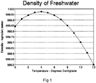
- water has its maximum density at 4°C. Therefore, as water in the headspace is cooled towards 4°C, its density will increase, and it will therefore tend to sink towards the bottom of the reservoir. Since the payload container will adopt a temperature at or around that of the surrounding water, it will tend towards 4°C, which is an ideal temperature for storage of vaccines and many other items.
- the payload container is separated from the cooling means, so avoiding the risk of its contents (or of its walls) dropping towards freezing point.
- the cooling means may include a refrigeration unit that can cool water within the headspace, and a power supply unit that can act as a source of power for the refrigeration unit.
- the power supply most typically includes means, such as photovoltaic cells, for converting sunlight into electrical power.
- the refrigeration unit includes an electrically-powered compressor.
- refrigeration units using other refrigeration technology might be used to increase the electrical efficiency of the refrigerator.
- One example of such alternative technology is a Stirling cooler, which may be operated in solar direct drive mode.
- a refrigerator having a refrigeration unit may further comprise a sensor disposed to detect the formation of ice in the reservoir.
- the sensor may be operative to cause operation of the refrigeration unit to be interrupted upon detection of the formation of ice.
- the cooling means includes a thermal mass that, for use, is at a temperature below a target temperature of the payload container.
- a thermal mass that, for use, is at a temperature below a target temperature of the payload container.
- the thermal mass may be a body of water ice.
- Such an arrangement may be used on its own or in combination with a refrigeration unit. This combination within the cooling means can cool the refrigerator to its working temperature better or more quickly than can the refrigeration unit alone.
- Such embodiments may include a compartment for receiving the thermal mass in thermal communication with water in the headspace.
- the compartment may be suitable for receiving ice.
- the thermal mass may be immersed in water within the headspace. In this latter case, the thermal mass may be an ice pack.
- the payload container is contained and submerged within the cooling region. This allows maximal heat transfer between the payload space and the water.
- the cooling region may be contained within a payload space. It may include one or more water-carrying passages that extend through the payload space, for example, in the form of a manifold. This arrangement may be simpler to construct, but the rate of heat transfer from the payload space to the water may be less.
- the headspace is located, in use, directly above the payload container.
- the payload container typically has an opening and a closure such as a door on one side of the payload container.
- the headspace may further be located, in use, to one side of the payload container.
- the payload container typically has an opening and a closure such as a door on the top of the payload container.
- a payload space within the payload container is in close thermal communication with the water in the reservoir. This ensures that the payload is maintained at a temperature approximately that of the water.
- the reservoir is insulated to minimise transfer of heat between water within the reservoir and surroundings of the refrigerator.
- Embodiments of the invention may further include a freezer compartment.
- the freezer compartment is in close thermal communication with a cooling element of the refrigeration unit. This ensures that it is cooled to a significantly lower temperature than the water.
- the freezer compartment may have an opening that is closed by an insulated door. The insulated door may or may not also close the payload container.
- An advantageous form of construction of embodiments of the invention may have an outer case within which is contained a water-containing liner.
- the liner may be formed of flexible plastic material.
- the outer case typically provides structural strength and thermal insulation for the refrigerator.
- the embodiment comprises a casing 10, which is, in this embodiment, shaped generally as an upright cuboid.
- the casing 10 is constructed to be a reservoir that, in use, contains a volume of water within an internal space 12.
- the casing 10 may be formed as a one-piece rotational moulding of plastic material.
- Insulating material 14 is carried on outer surfaces of the casing 10 to minimise flow of heat through the casing to or from the water contained within it. The water largely fills the internal space 12, but a small volume may be left unfilled to allow for expansion.
- a payload space 20 is formed within the casing 10.
- the payload space 20 is located within a generally cuboidal box 22 that has one open face that opens horizontally to the exterior of the casing.
- the typical volume of the payload space may be in the range of 50 to 100 litres, but other arrangements, for specialist purposes, may have greater or lesser capacities.
- the other faces are located within the casing 10 and are submerged under the water that is contained within the casing 10.
- the submerged faces of the cuboidal box 22 have no insulation so that they are in thermal communication with the surrounding water in a cooling region of the reservoir.
- the box 22 may optionally be integrally formed with the casing 10. When the refrigerator is disposed for use, the payload space 20 extends from close to the lowermost surface of the internal space 12 of the casing to appropriately half way towards the uppermost surface of the internal space 12.
- a door 24 is mounted on the casing 10.
- the door 24 can be opened to gain access to the payload space 20 through the open face. Insulating material is carried on the door 24 so that, when it is closed, it minimises the amount of heat that can be transferred through it into or out of the payload space 20.
- a refrigeration unit 30 is carried on a top surface of the casing 10.
- the refrigeration unit is a conventional electrical compressor-based cooling unit.
- the refrigeration unit 30 has a cooling element 32 that extends into the internal space 12 of the casing 10 and is submerged in the water.
- the cooling element 32 is located in a water-filled headspace above the box 22 such that it is spaced from the box 22 by a layer of water and likewise spaced from the uppermost surface of the internal space 12. (Alternatively, the refrigeration unit 30 may have a wrap-around evaporator that surrounds the headspace.)
- An optional ice probe 36 is located within the casing 10 above the box 22 but below the cooling element. The ice probe 36 is electrically connected to control the refrigeration unit 30, as will be described below.
- the refrigerator has an external power supply to feed the refrigeration unit 30.
- the power supply can operate from a supply of mains voltage (derived from a power grid or from a local generator) in the absence of bright sunlight.
- the power supply can also operate from photovoltaic panels, whereby the refrigeration unit 30 can be run without the need of a mains supply during sunny daytime conditions.
- the refrigeration unit 30 is run to cause its refrigeration element 32 to cool to a temperature that is typically well below the freezing point of water - for example, as low as -30°C. This, in turn, causes water in the immediate surroundings of the cooling element to cool. As the water cools, its density increases. This sets up an effect, whereby the cooled water sinks in the casing 10, so displacing warmer water below. This warmer water rises, and is, in turn, cooled. The average temperature of all of the water within the casing 10 falls. However, once the temperature of the water surrounding the cooling element 32 approaches 4°C, the rate of the effect decreases.
- the refrigeration unit 30 stops, assuming that ambient temperature is higher than the temperature of the water, energy will pass through the walls of the casing 10 into the water, which will start to warm.
- water in the lower part of the casing 10 will tend to stay around 4°C while the ice melts.
- the payload space 20 will be maintained at or around 4°C for as long as possible.
- a large amount of energy is required to melt ice - the latent heat of fusion.
- the payload of the refrigerator is therefore maintained at around 4°C, which is an ideal temperature for storage of vaccine and of food and drink.
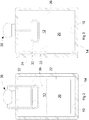
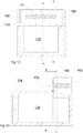
- Figures 4 and 5 show a second embodiment of the invention: this has essentially the same components as the first embodiment. However, their layout is somewhat different. In the following description, components of the second embodiment will be given reference signs that are 100 greater than the corresponding components of the first embodiment.
- the casing no is comparatively squatter in shape than that of the first embodiment.
- the opening of the box 122 faces upwards, and the door 124 opens upwards.
- Water surrounds the box on all sides but for the top opening, with the internal space 112 including an additional volume adjacent to one side of the box 122.
- a supplementary chamber 160 also containing water, is located on an upper surface of the box 122 above the additional headspace volume and adjacent to the door 124.
- a passage 162 interconnects the supplementary chamber 160 and the additional volume of the internal space 112 that allows water to pass between them.
- An ice sensor 136 is located adjacent to the passage 162 within the internal space 112.
- a refrigeration unit 130 is carried on an upper surface of the supplementary chamber 160, with a cooling element 132 extending from it into the supplementary chamber 160.
- This embodiment operates substantially as described above. Water that is cooled within the supplementary chamber passes into the internal space 112 through the passage 162. As before, the water that is densest - that is at round 4°C - sinks into the internal space 112 to cool the box 122 and the payload within it.
- the third and fourth embodiments add the ability to maintain items in a frozen condition to the first and second embodiments.
- the freezer compartment is in close thermal contact with a cooling element, such that it is cooled to a temperature well below that of the water.
- a freezer compartment 50 is provided, that has similar construction to the payload space 22, and similarly has a horizontal opening that is closed by the door 24.
- the freezer compartment 50 is located directly above the payload space, in close proximity to, or surrounded by, the cooling element 32 of the refrigeration unit 30.
- the opening of the freezer compartment 150 is horizontal and above that of the payload space 120. In the fourth embodiment, the opening of the freezer compartment 150 is horizontal and beside that of the payload space 120.
- the freezer compartment 150 is enclosed within the supplementary chamber 160, in close proximity to, or surrounded by, the cooling element 132 of the refrigeration unit 130.
- the freezer compartment 150 has an insulated door 152 that is separate from the door 124 of the payload space 120. The door 152 closes a horizontal opening of the freezer compartment 150.
- a fifth embodiment, shown in Figure 8 has a somewhat different construction from the previous embodiments, but operates on the same principles.
- the reservoir comprises an upper compartment 210 mounted above a payload container 220 to form a headspace.
- the reservoir includes first and second water ducts 212, 214 that extend generally downwards, when in use, into the payload container 220.
- the first duct 214 opens into the headspace at or close to a lowermost wall, while the second duct 214 extends upwards into water contained within the headspace.
- a manifold of several pipes 216 are connected to flow in parallel between the two ducts 212, 214.
- a refrigeration unit is provided with cooling elements 232 that can cool water within the headspace.
- the densest water will tend to flow towards the bottom of the reservoir - in this case, into the ducts 212, 214 and manifold 216 within the payload container 220, where heat can be exchanged between the water within the reservoir and the contents of the payload container 220.
- a thermosiphon process becomes established that transfers heat away from the payload container into the headspace as the temperature of the payload container falls towards 4°C.
- This performance is substantially beyond that required by the World Health Organization for vaccine storage, and is ideally suited for use with a power supply that relies upon energy derived from sunlight. It is significantly more than adequate to maintain the contents at the required temperature overnight, and, should it be necessary, through a period of cloudy weather when the supply of electrical power is limited. It should be noted that this level of performance is reached without any backup source of power such as a rechargeable battery.
- the maximum density of water occurs at 4°C, which is the case for pure water.
- the temperature at which the maximum density occurs can be altered by introduction of impurities into the water. For example, if salt is added to the water to a concentration of 3.5% (approximately that of sea water) then the maximum density occurs at nearer 2°C. This can be used to adjust the temperature of the payload space for specific applications.
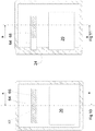
- Figures 10 to 13 simpler alternative embodiments of the invention are shown in Figures 10 to 13 .
- the embodiment of Figures 10 and 11 is similar to the third embodiment, and the embodiment of Figures 11 and 12 is similar to the fourth embodiment.
- the refrigeration unit 30, 310 and the associated cooling element 32, 132 is omitted. Consequentially, no source of electrical power is required.
- a watertight compartment 64 is provided.
- the compartment 64 extends into the headspace at substantially the same location as the freezer compartment 50, 150 of the earlier embodiments. Access to a space within the compartment 64 can be reached from an opening that is closed by a door 24, 152 in much the same way as the freezer compartments 50, 150.
- the material of the compartment 64 is chosen to have a high thermal conductivity to ensure efficient heat transfer between contents of the compartment 64 and water surrounding it.
- the compartment 64 is filled with a body of cold material 66, 166.
- the body of cold material 66, 166 is at a temperature that is below the intended operating temperature of the payload space 20, 120. It will typically be well below 0°C. A temperature of around -18°C can be obtained by placing the body in a conventional food freezer before use, and -30°C or less would emulate the effect of a refrigeration unit.
- heat is absorbed by the body of cold material from the water through the material of the compartment 64. In this way, the payload space 20, 120 is cooled by dense water cooled to approximately 4°C (or to another temperature at which the water and any of its additives is at its densest).
- the body of cold material can be anything with a suitable thermal mass.
- water ice is particularly suitable because it is readily available and has an advantageously high latent heat of fusion.
- the ice may be in the form of standard 0.6 litre ice packs 166 that are used in transport and storage of medical supplies. If ice packs are to be used, the compartment could be omitted altogether, with the ice packs being placed directly within the water of the headspace, as shown in Figures 12 and 13 . (Of course, the embodiment of Figures 12 and 13 could be modified to include a compartment as in the embodiment of Figures 10 and 11 , and the embodiment of Figures 10 and 11 could be modified by the omission of the compartment.)
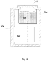
- FIG. 14 Another embodiment that makes use of a thermal mass is shown in Figure 14 .
- a container 364 is located above the payload container 320 submerged in water within the headspace.
- the container 364 is formed of a material that allows heat to be transferred from water within the headspace to its contents.
- the container 364 has an opening through which its interior can be reached from outside of the refrigerator, the opening being closed by a thermally-insulated cover 352. In this embodiment, the opening of the container faces upward when the refrigerator is in use.
- This embodiment functions in a manner similar to those described above that make use of a thermal mass.
- Cold material 366 most typically water ice
- Heat then moves from water in the headspace to the ice within the container, thereby cooling the water and the contents of the payload container 320, in accordance with the principles described above.
- the arrangement of the opening shown in Figure 14 allows the ice to be introduced quickly and easily into the container.
- a refrigerator with a payload space of 60 litres can be maintained within a required temperature range for between 7 and 30 days, with a requirement of 100 litres of ice to achieve the upper end of this range.
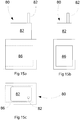
- a central requirement is that the water be maintained within the refrigerator in a manner that leakage and evaporation is prevented.
- the liner 80 will be shaped and dimensioned in accordance with the particular requirements with which it will be used, and that the figures illustrate just one exemplary configuration.
- the example shown in Figures 15a to 15c will be suitable for use in a front-entry refrigerator. It includes a headspace 82, a filling pipe 84, and a recess 86 within which the payload space is contained.
- the weight of the water causes the material of the liner 80 to deflect, so as to conform closely to the payload space, thereby ensuring effective heat transfer between the payload space and water within the liner 80. Small deflections of or damage to the outer case will not result in leakage of the liner 80. In the event that the liner does leak, it can be replaced readily and at little cost.
Applications Claiming Priority (3)
| Application Number | Priority Date | Filing Date | Title |
|---|---|---|---|
| GB0912286A GB2471865B (en) | 2009-07-15 | 2009-07-15 | Refrigeration apparatus |
| GB0916160A GB2471910A (en) | 2009-07-15 | 2009-09-15 | Refrigerator with a Container in Thermal Communication with a Water-Filled Reservoir |
| PCT/GB2010/051129 WO2011007162A2 (en) | 2009-07-15 | 2010-07-09 | Refrigeration apparatus |
Publications (2)
| Publication Number | Publication Date |
|---|---|
| EP2454539A2 EP2454539A2 (en) | 2012-05-23 |
| EP2454539B1 true EP2454539B1 (en) | 2017-11-08 |
Family
ID=41057993
Family Applications (1)
| Application Number | Title | Priority Date | Filing Date |
|---|---|---|---|
| EP10739675.6A Active EP2454539B1 (en) | 2009-07-15 | 2010-07-09 | Refrigeration apparatus |
Country Status (21)
| Country | Link |
|---|---|
| US (1) | US9618253B2 (zh) |
| EP (1) | EP2454539B1 (zh) |
| JP (2) | JP5852567B2 (zh) |
| KR (1) | KR101807171B1 (zh) |
| CN (2) | CN102483280B (zh) |
| AP (1) | AP3883A (zh) |
| AU (1) | AU2010272320B2 (zh) |
| BR (1) | BRPI1015971B1 (zh) |
| CA (1) | CA2767864C (zh) |
| CO (1) | CO6612198A2 (zh) |
| DK (1) | DK2454539T5 (zh) |
| EA (2) | EA030939B1 (zh) |
| GB (5) | GB2471865B (zh) |
| HK (3) | HK1148576A1 (zh) |
| MA (1) | MA33494B1 (zh) |
| MX (1) | MX338104B (zh) |
| MY (1) | MY154163A (zh) |
| SG (1) | SG176991A1 (zh) |
| TN (1) | TN2012000018A1 (zh) |
| WO (1) | WO2011007162A2 (zh) |
| ZA (2) | ZA201103063B (zh) |
Cited By (1)
| Publication number | Priority date | Publication date | Assignee | Title |
|---|---|---|---|---|
| FR3139623A1 (fr) | 2022-07-26 | 2024-03-15 | Koolboks | Système de réfrigération à énergie renouvelable comprenant une armoire réfrigérée |
Families Citing this family (26)
| Publication number | Priority date | Publication date | Assignee | Title |
|---|---|---|---|---|
| GB2471865B (en) | 2009-07-15 | 2011-06-29 | Bright Light Solar Ltd | Refrigeration apparatus |
| CN104364592B (zh) * | 2012-01-27 | 2018-02-06 | 确保冷藏有限公司 | 制冷设备 |
| GB201300885D0 (en) * | 2013-01-17 | 2013-03-06 | True Energy Ltd | Cooling Apparatus |
| GB201301494D0 (en) | 2013-01-28 | 2013-03-13 | True Energy Ltd | Refrigeration apparatus |
| US11105556B2 (en) | 2013-03-29 | 2021-08-31 | Tokitae, LLC | Temperature-controlled portable cooling units |
| CN105556224B (zh) | 2013-07-23 | 2019-10-11 | 确保冷藏有限公司 | 制冷装置及方法 |
| US9366483B2 (en) | 2013-11-27 | 2016-06-14 | Tokitac LLC | Temperature-controlled container systems for use within a refrigeration device |
| US9726418B2 (en) | 2013-11-27 | 2017-08-08 | Tokitae Llc | Refrigeration devices including temperature-controlled container systems |
| US9523522B2 (en) | 2013-11-27 | 2016-12-20 | Tokitae Llc | Refrigeration devices including temperature-controlled container systems |
| SG11201700928VA (en) * | 2014-08-08 | 2017-03-30 | Tokitae Llc | Temperature-controlled medicinal storage devices |
| CN105987555A (zh) * | 2015-03-06 | 2016-10-05 | 青岛海尔股份有限公司 | 冰水蓄冷恒温冷藏箱及控制方法 |
| WO2016164320A1 (en) * | 2015-04-06 | 2016-10-13 | The Sure Chill Company Limited | Mobile refrigeration apparatus |
| WO2017044934A1 (en) | 2015-09-11 | 2017-03-16 | The Sure Chill Company Limited | Portable refrigeration apparatus |
| JP6090407B1 (ja) * | 2015-10-27 | 2017-03-08 | 三菱電機株式会社 | 保存移動装置 |
| CN106500386B (zh) * | 2016-12-28 | 2022-12-30 | 宁波华斯特林电机制造有限公司 | 基于斯特林电机的冷却装置 |
| EP3589901B1 (en) * | 2017-02-28 | 2021-04-07 | B Medical Systems S.à.r.l. | Vaccine carrier with a passive cooling system |
| CN108895742A (zh) * | 2018-04-13 | 2018-11-27 | 西安工程大学 | 一种新型便携式家用冰箱 |
| CA3095760A1 (en) | 2018-04-19 | 2019-10-24 | Ember Technologies, Inc. | Portable cooler with active temperature control |
| GB2575859B (en) | 2018-07-26 | 2022-03-30 | B Medical Systems Sarl | Ice-lined vaccine refrigerator |
| WO2020146394A2 (en) | 2019-01-11 | 2020-07-16 | Ember Technologies, Inc. | Portable cooler with active temperature control |
| CA3143365A1 (en) | 2019-06-25 | 2020-12-30 | Ember Technologies, Inc. | Portable cooler |
| US11668508B2 (en) | 2019-06-25 | 2023-06-06 | Ember Technologies, Inc. | Portable cooler |
| US11162716B2 (en) | 2019-06-25 | 2021-11-02 | Ember Technologies, Inc. | Portable cooler |
| WO2021150241A1 (en) * | 2020-01-24 | 2021-07-29 | Nobotech, Llc | Regulator system and method for regulating liquid bulk gas containers |
| CN114735336B (zh) * | 2022-06-09 | 2022-08-30 | 郑州人民医院(郑州人民医院医疗管理中心) | 一种肾脏转运储存箱 |
| KR20240045503A (ko) | 2022-09-30 | 2024-04-08 | 충남대학교산학협력단 | 백신의 동결 손상 방지를 위한 과냉각 보존 장치 |
Citations (1)
| Publication number | Priority date | Publication date | Assignee | Title |
|---|---|---|---|---|
| US4321802A (en) * | 1979-07-05 | 1982-03-30 | Hoshizaki Electric Co., Ltd. | Ice and water-making refrigeration apparatus |
Family Cites Families (78)
| Publication number | Priority date | Publication date | Assignee | Title |
|---|---|---|---|---|
| US186200A (en) | 1877-01-16 | Improvement in refrigerators | ||
| GB165684A (en) * | 1920-08-16 | 1921-07-07 | Fred John Heideman | Improvements in refrigerating tanks for refrigerators |
| US1594015A (en) | 1926-01-19 | 1926-07-27 | Mclaughlin William | Beverage cooler and dispenser |
| US1988549A (en) | 1930-09-30 | 1935-01-22 | Frigidaire Corp | Refrigerating apparatus |
| US2046967A (en) | 1932-08-03 | 1936-07-07 | Int Motor Co | Refrigerating mechanism |
| GB494531A (en) | 1937-06-08 | 1938-10-27 | Harry Aldam | Improvements in or relating to refrigeration apparatus |
| US2641109A (en) | 1947-08-29 | 1953-06-09 | Muffly Glenn | Multitemperature refrigerating system |
| JPS4827260B1 (zh) * | 1967-08-08 | 1973-08-21 | ||
| US3609991A (en) | 1969-10-13 | 1971-10-05 | Ibm | Cooling system having thermally induced circulation |
| JPS4936282Y1 (zh) * | 1970-10-07 | 1974-10-03 | ||
| GB1429678A (en) | 1973-03-28 | 1976-03-24 | Distillers Co Carbon Dioxide | Apparatus for supplying liquid carbon dioxide |
| SU898226A1 (ru) * | 1979-09-21 | 1982-01-15 | Львовский Ордена Ленина Политехнический Институт Им. Ленинского Комсомола | Бытовой термоэлектрический холодильник |
| JPS614190Y2 (zh) * | 1979-11-06 | 1986-02-08 | ||
| EP0038864A1 (de) * | 1980-04-24 | 1981-11-04 | Eberlein & Co. | Kühlbox |
| US4509587A (en) | 1982-08-30 | 1985-04-09 | Clark Thomas S | Passive temperature control shipment container |
| FR2537712A1 (fr) | 1982-12-08 | 1984-06-15 | Droit Philippe | Echangeur thermique destine a des appareils pour conditionnement en temperature |
| JPS60108977U (ja) * | 1983-12-28 | 1985-07-24 | 株式会社東芝 | 冷温水機 |
| FR2562218B1 (fr) * | 1984-03-29 | 1987-03-20 | Elf Aquitaine | Refrigerateur alimente a l'energie solaire |
| DD240333A1 (de) | 1985-08-19 | 1986-10-29 | Univ Rostock | Kuehlcontainer insbesondere fuer spendeorgane |
| JPS63113872U (zh) * | 1987-01-19 | 1988-07-22 | ||
| US4715195A (en) | 1987-06-02 | 1987-12-29 | Iosif Kucza | Apparatus for rapid cooling of containers |
| FR2628077B1 (fr) * | 1988-03-07 | 1990-08-03 | Guilhem Jacques | Conteneur pour le transport de greffons |
| CN2062629U (zh) | 1988-12-30 | 1990-09-26 | 李耀忠 | 多功能气功效应仪 |
| GB2235968B (en) * | 1989-08-11 | 1993-01-13 | Booth Dispensers | Improvements in or relating to heat exchange |
| FR2660738B1 (fr) * | 1990-04-05 | 1994-10-28 | Cma | Installation permettant de realiser la refrigeration (ou rechauffement) rapide de produits emballes, notamment de bouteilles. |
| JPH0725578Y2 (ja) * | 1990-11-07 | 1995-06-07 | 大同ほくさん株式会社 | 保冷兼凍結冷却装置 |
| US5129238A (en) | 1990-11-30 | 1992-07-14 | Schwartz James A | Soft drink container cooler |
| BE1004012A3 (fr) | 1990-12-17 | 1992-09-08 | F R J Concept | Dispositif pour rafraichir des liquides contenus dans des recipients. |
| CA2140517C (en) | 1991-03-20 | 1998-06-30 | Yutaka Hachinohe | Low temperature food storage process |
| JPH0744929Y2 (ja) * | 1991-05-28 | 1995-10-11 | ホシザキ電機株式会社 | 冷水供給装置付き貯氷庫 |
| JP3108155B2 (ja) * | 1991-09-19 | 2000-11-13 | 三洋電機株式会社 | 冷水ショ−ケ−ス |
| DE4142842A1 (de) * | 1991-09-26 | 1993-04-01 | Wolfgang Wasserthal | Tragbares kuehlbehaeltnis |
| JPH05248754A (ja) * | 1992-03-09 | 1993-09-24 | Sanyo Electric Co Ltd | 冷却庫 |
| AU5670294A (en) * | 1992-11-20 | 1994-06-22 | Grumman Aerospace Corporation | Self-contained cooler/freezer apparatus |
| US5627310A (en) * | 1992-12-10 | 1997-05-06 | Imi Cornelius, Inc. | Sensor arrangement for ice bank control |
| CN2162269Y (zh) | 1993-06-18 | 1994-04-20 | 郁苏 | 发光跳棋 |
| US5408845A (en) | 1993-09-08 | 1995-04-25 | Microchill Int Ltd | Cooling or chilling apparatus |
| DE4425213A1 (de) * | 1994-07-16 | 1996-01-18 | Helmut Kuhn | Solarkühlschrank |
| JPH10144361A (ja) | 1996-11-12 | 1998-05-29 | Furukawa Electric Co Ltd:The | バッテリーシステムとそれを備えた輸送機械 |
| US5782095A (en) | 1997-09-18 | 1998-07-21 | General Electric Company | Cryogen recondensing superconducting magnet |
| US6253563B1 (en) * | 1999-06-03 | 2001-07-03 | The United States Of America As Represented By The Administrator Of The National Aeronautics And Space Administration | Solar-powered refrigeration system |
| CN2379760Y (zh) | 1999-06-09 | 2000-05-24 | 李丽芬 | 饮料桶保冷装置 |
| JP2001133109A (ja) * | 1999-10-29 | 2001-05-18 | Toshiba Electric Appliance Co Ltd | 冷水注出装置 |
| JP2001221553A (ja) * | 2000-02-07 | 2001-08-17 | Sharp Corp | 保冷庫 |
| JP2001227847A (ja) * | 2000-02-14 | 2001-08-24 | Masashi Ogoshi | 氷冷庫内蔵型製氷機 |
| CN1426523A (zh) * | 2000-04-27 | 2003-06-25 | 夏普公司 | 保冷箱 |
| JP3614349B2 (ja) | 2000-06-27 | 2005-01-26 | 象印マホービン株式会社 | 液体容器冷却装置 |
| US6415624B1 (en) | 2000-08-25 | 2002-07-09 | Frank R. Connors | Drinking bottle having a separate thermally regulating container |
| US6314751B1 (en) | 2000-11-17 | 2001-11-13 | Gilbert Sebastian Gjersvik | Beverage chilling apparatus |
| US20020104318A1 (en) * | 2001-02-08 | 2002-08-08 | Ali Jaafar | Miniature thermoelectric cooler |
| US6656380B2 (en) * | 2001-10-16 | 2003-12-02 | Supachill Technologies Pty. Ltd. | Super-coolable composition having long-duration phase change capability, process for preparation of same, process for super-cooling same and articles comprising same |
| JP2003148849A (ja) * | 2001-11-06 | 2003-05-21 | Biobank Co Ltd | ポータブル型医療用臓器冷蔵保存容器 |
| JP4556019B2 (ja) * | 2002-05-24 | 2010-10-06 | 日本通運株式会社 | 配送用保冷容器 |
| US7069739B2 (en) | 2002-12-18 | 2006-07-04 | Porter Michael A | Device for cooling or heating liquids in a bottle |
| DE10261366A1 (de) | 2002-12-30 | 2004-07-08 | BSH Bosch und Siemens Hausgeräte GmbH | Hilfskühlvorrichtung |
| AU2004224781B2 (en) * | 2003-03-24 | 2007-11-22 | Unilever Plc | Refrigerated display and dispensing assembly |
| SE0303234D0 (sv) | 2003-12-01 | 2003-12-01 | Dometic Sweden Ab | Refrigerator and method |
| US6948333B1 (en) | 2004-04-19 | 2005-09-27 | Akopyan Arshak Sh | Combined bottles with hidden cooler |
| US7296434B2 (en) * | 2004-06-22 | 2007-11-20 | Scroggs Donald T | Cooler |
| WO2006007663A1 (en) | 2004-07-22 | 2006-01-26 | Era (Environmental Refrigeration Alternatives) Pty Ltd | Refrigeration system |
| JP2007085635A (ja) * | 2005-09-21 | 2007-04-05 | Twinbird Corp | 液体冷却装置 |
| GB2430724B (en) | 2005-09-28 | 2007-09-12 | Yiu Wing Ng | Bottle cooler |
| KR100729962B1 (ko) * | 2005-10-21 | 2007-06-19 | 청호나이스 주식회사 | 하나의 증발기로 제빙과 동시에 냉수를 얻을 수 있는냉온정수시스템 및 장치 |
| US20090151368A1 (en) * | 2006-08-08 | 2009-06-18 | Ewa Tech Ltd. | Method and apparatus for extracting water from atmospheric air and utilizing the same |
| US7640764B2 (en) | 2006-09-08 | 2010-01-05 | Adroit Medical Systems, Inc. | Portable coolant system |
| JP2008086608A (ja) * | 2006-10-03 | 2008-04-17 | Twinbird Corp | 血液製剤の搬送装置 |
| DE102006058629B3 (de) | 2006-12-13 | 2008-07-10 | Schuler Pressen Gmbh & Co. Kg | Kühlanordnung für einen Kondensator |
| JP2009030961A (ja) | 2007-06-29 | 2009-02-12 | Mutsu Tsunoda | 冷却庫 |
| NL2001054C2 (nl) | 2007-12-04 | 2009-06-08 | Heineken Supply Chain Bv | Koeler en werkwijze voor koeling van drankhouders zoals flessen en blikjes. |
| GB2457054B (en) | 2008-01-31 | 2010-01-06 | Siemens Magnet Technology Ltd | A method and apparatus for controlling the cooling power of a cryogenic refigerator delivered to a cryogen vessel |
| US7543455B1 (en) * | 2008-06-06 | 2009-06-09 | Chengjun Julian Chen | Solar-powered refrigerator using a mixture of glycerin, alcohol and water to store energy |
| DE102009006426A1 (de) | 2009-01-28 | 2010-07-29 | Li-Tec Battery Gmbh | Batterie mit Gehäuse |
| GB2471865B (en) | 2009-07-15 | 2011-06-29 | Bright Light Solar Ltd | Refrigeration apparatus |
| CN201451827U (zh) | 2009-07-21 | 2010-05-12 | 成都峻峰科技开发有限公司 | 保鲜餐盒 |
| CN103988144B (zh) | 2011-12-13 | 2018-06-19 | 英特尔公司 | 使用自泵抽流体的计算设备冷却技术 |
| CN104364592B (zh) | 2012-01-27 | 2018-02-06 | 确保冷藏有限公司 | 制冷设备 |
| GB201301494D0 (en) | 2013-01-28 | 2013-03-13 | True Energy Ltd | Refrigeration apparatus |
| CN105556224B (zh) | 2013-07-23 | 2019-10-11 | 确保冷藏有限公司 | 制冷装置及方法 |
-
2009
- 2009-07-15 GB GB0912286A patent/GB2471865B/en active Active
- 2009-09-15 GB GB1115918.3A patent/GB2482993B/en active Active
- 2009-09-15 GB GB0916160A patent/GB2471910A/en not_active Withdrawn
-
2010
- 2010-07-09 AP AP2012006111A patent/AP3883A/en active
- 2010-07-09 CA CA2767864A patent/CA2767864C/en active Active
- 2010-07-09 US US13/383,118 patent/US9618253B2/en active Active
- 2010-07-09 EA EA201790498A patent/EA030939B1/ru not_active IP Right Cessation
- 2010-07-09 DK DK10739675.6T patent/DK2454539T5/en active
- 2010-07-09 WO PCT/GB2010/051129 patent/WO2011007162A2/en active Application Filing
- 2010-07-09 CN CN201080041090.9A patent/CN102483280B/zh active Active
- 2010-07-09 BR BRPI1015971-1A patent/BRPI1015971B1/pt active IP Right Grant
- 2010-07-09 MY MYPI2011006368A patent/MY154163A/en unknown
- 2010-07-09 MX MX2012000719A patent/MX338104B/es active IP Right Grant
- 2010-07-09 GB GB1202625.8A patent/GB2486094B/en active Active
- 2010-07-09 CN CN201510186465.5A patent/CN104976843B/zh active Active
- 2010-07-09 KR KR1020127000384A patent/KR101807171B1/ko active IP Right Grant
- 2010-07-09 JP JP2012520097A patent/JP5852567B2/ja active Active
- 2010-07-09 EA EA201270161A patent/EA027555B9/ru not_active IP Right Cessation
- 2010-07-09 MA MA34536A patent/MA33494B1/fr unknown
- 2010-07-09 AU AU2010272320A patent/AU2010272320B2/en active Active
- 2010-07-09 EP EP10739675.6A patent/EP2454539B1/en active Active
- 2010-07-09 SG SG2011096609A patent/SG176991A1/en unknown
-
2011
- 2011-03-08 HK HK11102373.0A patent/HK1148576A1/xx unknown
- 2011-04-21 ZA ZA2011/03063A patent/ZA201103063B/en unknown
- 2011-09-13 GB GBGB1115835.9A patent/GB201115835D0/en not_active Ceased
-
2012
- 2012-01-13 TN TNP2012000018A patent/TN2012000018A1/en unknown
- 2012-02-15 CO CO12026762A patent/CO6612198A2/es unknown
- 2012-03-01 HK HK12102147.4A patent/HK1161637A1/xx unknown
- 2012-09-07 ZA ZA2012/06710A patent/ZA201206710B/en unknown
- 2012-10-29 HK HK12110817.6A patent/HK1170020A1/xx unknown
-
2015
- 2015-12-03 JP JP2015236753A patent/JP2016029334A/ja active Pending
Patent Citations (1)
| Publication number | Priority date | Publication date | Assignee | Title |
|---|---|---|---|---|
| US4321802A (en) * | 1979-07-05 | 1982-03-30 | Hoshizaki Electric Co., Ltd. | Ice and water-making refrigeration apparatus |
Cited By (1)
| Publication number | Priority date | Publication date | Assignee | Title |
|---|---|---|---|---|
| FR3139623A1 (fr) | 2022-07-26 | 2024-03-15 | Koolboks | Système de réfrigération à énergie renouvelable comprenant une armoire réfrigérée |
Also Published As
Similar Documents
| Publication | Publication Date | Title |
|---|---|---|
| EP2454539B1 (en) | Refrigeration apparatus | |
| US9909799B2 (en) | Refrigeration apparatus | |
| US6308518B1 (en) | Thermal barrier enclosure system | |
| KR102155595B1 (ko) | 냉장 장치 | |
| CN107567571B (zh) | 冷却装置 | |
| CN110595129B (zh) | 制冷装置及方法 | |
| AU2001286740B2 (en) | Thermal barrier enclosure system | |
| AU2015202391A1 (en) | Refrigeration apparatus | |
| GB2498777A (en) | Refrigeration apparatus with fluid control between a reservoir and a headspace |
Legal Events
| Date | Code | Title | Description |
|---|---|---|---|
| PUAI | Public reference made under article 153(3) epc to a published international application that has entered the european phase |
Free format text: ORIGINAL CODE: 0009012 |
|
| 17P | Request for examination filed |
Effective date: 20120215 |
|
| AK | Designated contracting states |
Kind code of ref document: A2 Designated state(s): AL AT BE BG CH CY CZ DE DK EE ES FI FR GB GR HR HU IE IS IT LI LT LU LV MC MK MT NL NO PL PT RO SE SI SK SM TR |
|
| DAX | Request for extension of the european patent (deleted) | ||
| 17Q | First examination report despatched |
Effective date: 20160217 |
|
| REG | Reference to a national code |
Ref country code: DE Ref legal event code: R079 Ref document number: 602010046537 Country of ref document: DE Free format text: PREVIOUS MAIN CLASS: F25D0011000000 Ipc: F25B0027000000 |
|
| GRAP | Despatch of communication of intention to grant a patent |
Free format text: ORIGINAL CODE: EPIDOSNIGR1 |
|
| RIC1 | Information provided on ipc code assigned before grant |
Ipc: F25B 27/00 20060101AFI20170427BHEP Ipc: F25D 16/00 20060101ALI20170427BHEP Ipc: F25D 11/00 20060101ALI20170427BHEP |
|
| INTG | Intention to grant announced |
Effective date: 20170524 |
|
| RAP1 | Party data changed (applicant data changed or rights of an application transferred) |
Owner name: THE SURE CHILL COMPANY LIMITED |
|
| GRAS | Grant fee paid |
Free format text: ORIGINAL CODE: EPIDOSNIGR3 |
|
| GRAA | (expected) grant |
Free format text: ORIGINAL CODE: 0009210 |
|
| AK | Designated contracting states |
Kind code of ref document: B1 Designated state(s): AL AT BE BG CH CY CZ DE DK EE ES FI FR GB GR HR HU IE IS IT LI LT LU LV MC MK MT NL NO PL PT RO SE SI SK SM TR |
|
| REG | Reference to a national code |
Ref country code: GB Ref legal event code: FG4D |
|
| REG | Reference to a national code |
Ref country code: CH Ref legal event code: EP Ref country code: AT Ref legal event code: REF Ref document number: 944515 Country of ref document: AT Kind code of ref document: T Effective date: 20171115 |
|
| REG | Reference to a national code |
Ref country code: IE Ref legal event code: FG4D |
|
| REG | Reference to a national code |
Ref country code: DE Ref legal event code: R096 Ref document number: 602010046537 Country of ref document: DE |
|
| REG | Reference to a national code |
Ref country code: DK Ref legal event code: T3 Effective date: 20180206 |
|
| REG | Reference to a national code |
Ref country code: DK Ref legal event code: T5 Effective date: 20180212 |
|
| REG | Reference to a national code |
Ref country code: NL Ref legal event code: MP Effective date: 20171108 |
|
| REG | Reference to a national code |
Ref country code: LT Ref legal event code: MG4D |
|
| REG | Reference to a national code |
Ref country code: AT Ref legal event code: MK05 Ref document number: 944515 Country of ref document: AT Kind code of ref document: T Effective date: 20171108 |
|
| PG25 | Lapsed in a contracting state [announced via postgrant information from national office to epo] |
Ref country code: LT Free format text: LAPSE BECAUSE OF FAILURE TO SUBMIT A TRANSLATION OF THE DESCRIPTION OR TO PAY THE FEE WITHIN THE PRESCRIBED TIME-LIMIT Effective date: 20171108 Ref country code: SE Free format text: LAPSE BECAUSE OF FAILURE TO SUBMIT A TRANSLATION OF THE DESCRIPTION OR TO PAY THE FEE WITHIN THE PRESCRIBED TIME-LIMIT Effective date: 20171108 Ref country code: FI Free format text: LAPSE BECAUSE OF FAILURE TO SUBMIT A TRANSLATION OF THE DESCRIPTION OR TO PAY THE FEE WITHIN THE PRESCRIBED TIME-LIMIT Effective date: 20171108 Ref country code: NO Free format text: LAPSE BECAUSE OF FAILURE TO SUBMIT A TRANSLATION OF THE DESCRIPTION OR TO PAY THE FEE WITHIN THE PRESCRIBED TIME-LIMIT Effective date: 20180208 Ref country code: ES Free format text: LAPSE BECAUSE OF FAILURE TO SUBMIT A TRANSLATION OF THE DESCRIPTION OR TO PAY THE FEE WITHIN THE PRESCRIBED TIME-LIMIT Effective date: 20171108 Ref country code: NL Free format text: LAPSE BECAUSE OF FAILURE TO SUBMIT A TRANSLATION OF THE DESCRIPTION OR TO PAY THE FEE WITHIN THE PRESCRIBED TIME-LIMIT Effective date: 20171108 |
|
| PG25 | Lapsed in a contracting state [announced via postgrant information from national office to epo] |
Ref country code: BG Free format text: LAPSE BECAUSE OF FAILURE TO SUBMIT A TRANSLATION OF THE DESCRIPTION OR TO PAY THE FEE WITHIN THE PRESCRIBED TIME-LIMIT Effective date: 20180208 Ref country code: HR Free format text: LAPSE BECAUSE OF FAILURE TO SUBMIT A TRANSLATION OF THE DESCRIPTION OR TO PAY THE FEE WITHIN THE PRESCRIBED TIME-LIMIT Effective date: 20171108 Ref country code: GR Free format text: LAPSE BECAUSE OF FAILURE TO SUBMIT A TRANSLATION OF THE DESCRIPTION OR TO PAY THE FEE WITHIN THE PRESCRIBED TIME-LIMIT Effective date: 20180209 Ref country code: LV Free format text: LAPSE BECAUSE OF FAILURE TO SUBMIT A TRANSLATION OF THE DESCRIPTION OR TO PAY THE FEE WITHIN THE PRESCRIBED TIME-LIMIT Effective date: 20171108 Ref country code: IS Free format text: LAPSE BECAUSE OF FAILURE TO SUBMIT A TRANSLATION OF THE DESCRIPTION OR TO PAY THE FEE WITHIN THE PRESCRIBED TIME-LIMIT Effective date: 20180308 Ref country code: AT Free format text: LAPSE BECAUSE OF FAILURE TO SUBMIT A TRANSLATION OF THE DESCRIPTION OR TO PAY THE FEE WITHIN THE PRESCRIBED TIME-LIMIT Effective date: 20171108 |
|
| REG | Reference to a national code |
Ref country code: FR Ref legal event code: PLFP Year of fee payment: 9 |
|
| PG25 | Lapsed in a contracting state [announced via postgrant information from national office to epo] |
Ref country code: SK Free format text: LAPSE BECAUSE OF FAILURE TO SUBMIT A TRANSLATION OF THE DESCRIPTION OR TO PAY THE FEE WITHIN THE PRESCRIBED TIME-LIMIT Effective date: 20171108 Ref country code: CZ Free format text: LAPSE BECAUSE OF FAILURE TO SUBMIT A TRANSLATION OF THE DESCRIPTION OR TO PAY THE FEE WITHIN THE PRESCRIBED TIME-LIMIT Effective date: 20171108 Ref country code: CY Free format text: LAPSE BECAUSE OF FAILURE TO SUBMIT A TRANSLATION OF THE DESCRIPTION OR TO PAY THE FEE WITHIN THE PRESCRIBED TIME-LIMIT Effective date: 20171108 Ref country code: EE Free format text: LAPSE BECAUSE OF FAILURE TO SUBMIT A TRANSLATION OF THE DESCRIPTION OR TO PAY THE FEE WITHIN THE PRESCRIBED TIME-LIMIT Effective date: 20171108 |
|
| REG | Reference to a national code |
Ref country code: DE Ref legal event code: R097 Ref document number: 602010046537 Country of ref document: DE |
|
| PG25 | Lapsed in a contracting state [announced via postgrant information from national office to epo] |
Ref country code: PL Free format text: LAPSE BECAUSE OF FAILURE TO SUBMIT A TRANSLATION OF THE DESCRIPTION OR TO PAY THE FEE WITHIN THE PRESCRIBED TIME-LIMIT Effective date: 20171108 Ref country code: SM Free format text: LAPSE BECAUSE OF FAILURE TO SUBMIT A TRANSLATION OF THE DESCRIPTION OR TO PAY THE FEE WITHIN THE PRESCRIBED TIME-LIMIT Effective date: 20171108 Ref country code: IT Free format text: LAPSE BECAUSE OF FAILURE TO SUBMIT A TRANSLATION OF THE DESCRIPTION OR TO PAY THE FEE WITHIN THE PRESCRIBED TIME-LIMIT Effective date: 20171108 Ref country code: RO Free format text: LAPSE BECAUSE OF FAILURE TO SUBMIT A TRANSLATION OF THE DESCRIPTION OR TO PAY THE FEE WITHIN THE PRESCRIBED TIME-LIMIT Effective date: 20171108 |
|
| PLBE | No opposition filed within time limit |
Free format text: ORIGINAL CODE: 0009261 |
|
| STAA | Information on the status of an ep patent application or granted ep patent |
Free format text: STATUS: NO OPPOSITION FILED WITHIN TIME LIMIT |
|
| 26N | No opposition filed |
Effective date: 20180809 |
|
| PG25 | Lapsed in a contracting state [announced via postgrant information from national office to epo] |
Ref country code: SI Free format text: LAPSE BECAUSE OF FAILURE TO SUBMIT A TRANSLATION OF THE DESCRIPTION OR TO PAY THE FEE WITHIN THE PRESCRIBED TIME-LIMIT Effective date: 20171108 |
|
| REG | Reference to a national code |
Ref country code: CH Ref legal event code: PL |
|
| PG25 | Lapsed in a contracting state [announced via postgrant information from national office to epo] |
Ref country code: MC Free format text: LAPSE BECAUSE OF FAILURE TO SUBMIT A TRANSLATION OF THE DESCRIPTION OR TO PAY THE FEE WITHIN THE PRESCRIBED TIME-LIMIT Effective date: 20171108 |
|
| REG | Reference to a national code |
Ref country code: BE Ref legal event code: MM Effective date: 20180731 |
|
| REG | Reference to a national code |
Ref country code: IE Ref legal event code: MM4A |
|
| PG25 | Lapsed in a contracting state [announced via postgrant information from national office to epo] |
Ref country code: CH Free format text: LAPSE BECAUSE OF NON-PAYMENT OF DUE FEES Effective date: 20180731 Ref country code: IE Free format text: LAPSE BECAUSE OF NON-PAYMENT OF DUE FEES Effective date: 20180709 Ref country code: LI Free format text: LAPSE BECAUSE OF NON-PAYMENT OF DUE FEES Effective date: 20180731 |
|
| PG25 | Lapsed in a contracting state [announced via postgrant information from national office to epo] |
Ref country code: BE Free format text: LAPSE BECAUSE OF NON-PAYMENT OF DUE FEES Effective date: 20180731 |
|
| PG25 | Lapsed in a contracting state [announced via postgrant information from national office to epo] |
Ref country code: MT Free format text: LAPSE BECAUSE OF NON-PAYMENT OF DUE FEES Effective date: 20180709 |
|
| PG25 | Lapsed in a contracting state [announced via postgrant information from national office to epo] |
Ref country code: TR Free format text: LAPSE BECAUSE OF FAILURE TO SUBMIT A TRANSLATION OF THE DESCRIPTION OR TO PAY THE FEE WITHIN THE PRESCRIBED TIME-LIMIT Effective date: 20171108 |
|
| PG25 | Lapsed in a contracting state [announced via postgrant information from national office to epo] |
Ref country code: HU Free format text: LAPSE BECAUSE OF FAILURE TO SUBMIT A TRANSLATION OF THE DESCRIPTION OR TO PAY THE FEE WITHIN THE PRESCRIBED TIME-LIMIT; INVALID AB INITIO Effective date: 20100709 Ref country code: PT Free format text: LAPSE BECAUSE OF FAILURE TO SUBMIT A TRANSLATION OF THE DESCRIPTION OR TO PAY THE FEE WITHIN THE PRESCRIBED TIME-LIMIT Effective date: 20171108 |
|
| PG25 | Lapsed in a contracting state [announced via postgrant information from national office to epo] |
Ref country code: MK Free format text: LAPSE BECAUSE OF NON-PAYMENT OF DUE FEES Effective date: 20171108 |
|
| PG25 | Lapsed in a contracting state [announced via postgrant information from national office to epo] |
Ref country code: AL Free format text: LAPSE BECAUSE OF FAILURE TO SUBMIT A TRANSLATION OF THE DESCRIPTION OR TO PAY THE FEE WITHIN THE PRESCRIBED TIME-LIMIT Effective date: 20171108 |
|
| PGFP | Annual fee paid to national office [announced via postgrant information from national office to epo] |
Ref country code: FR Payment date: 20230620 Year of fee payment: 14 Ref country code: DK Payment date: 20230627 Year of fee payment: 14 |
|
| PGFP | Annual fee paid to national office [announced via postgrant information from national office to epo] |
Ref country code: LU Payment date: 20230628 Year of fee payment: 14 |
|
| P01 | Opt-out of the competence of the unified patent court (upc) registered |
Effective date: 20230815 |
|
| PGFP | Annual fee paid to national office [announced via postgrant information from national office to epo] |
Ref country code: GB Payment date: 20230601 Year of fee payment: 14 |
|
| PGFP | Annual fee paid to national office [announced via postgrant information from national office to epo] |
Ref country code: DE Payment date: 20230531 Year of fee payment: 14 |