EP2453799B1 - Auslösen eines intraoralen röntgenstrahlsensors unter verwendung einer pixel-anordnungs-unterprobennahme - Google Patents
Auslösen eines intraoralen röntgenstrahlsensors unter verwendung einer pixel-anordnungs-unterprobennahme Download PDFInfo
- Publication number
- EP2453799B1 EP2453799B1 EP10800232.0A EP10800232A EP2453799B1 EP 2453799 B1 EP2453799 B1 EP 2453799B1 EP 10800232 A EP10800232 A EP 10800232A EP 2453799 B1 EP2453799 B1 EP 2453799B1
- Authority
- EP
- European Patent Office
- Prior art keywords
- pixels
- pixel
- array
- ray
- clusters
- Prior art date
- Legal status (The legal status is an assumption and is not a legal conclusion. Google has not performed a legal analysis and makes no representation as to the accuracy of the status listed.)
- Not-in-force
Links
Images



Classifications
-
- A—HUMAN NECESSITIES
- A61—MEDICAL OR VETERINARY SCIENCE; HYGIENE
- A61B—DIAGNOSIS; SURGERY; IDENTIFICATION
- A61B6/00—Apparatus or devices for radiation diagnosis; Apparatus or devices for radiation diagnosis combined with radiation therapy equipment
- A61B6/50—Apparatus or devices for radiation diagnosis; Apparatus or devices for radiation diagnosis combined with radiation therapy equipment specially adapted for specific body parts; specially adapted for specific clinical applications
- A61B6/51—Apparatus or devices for radiation diagnosis; Apparatus or devices for radiation diagnosis combined with radiation therapy equipment specially adapted for specific body parts; specially adapted for specific clinical applications for dentistry
- A61B6/512—Intraoral means
-
- A—HUMAN NECESSITIES
- A61—MEDICAL OR VETERINARY SCIENCE; HYGIENE
- A61B—DIAGNOSIS; SURGERY; IDENTIFICATION
- A61B6/00—Apparatus or devices for radiation diagnosis; Apparatus or devices for radiation diagnosis combined with radiation therapy equipment
- A61B6/42—Arrangements for detecting radiation specially adapted for radiation diagnosis
- A61B6/4208—Arrangements for detecting radiation specially adapted for radiation diagnosis characterised by using a particular type of detector
- A61B6/4233—Arrangements for detecting radiation specially adapted for radiation diagnosis characterised by using a particular type of detector using matrix detectors
-
- A—HUMAN NECESSITIES
- A61—MEDICAL OR VETERINARY SCIENCE; HYGIENE
- A61B—DIAGNOSIS; SURGERY; IDENTIFICATION
- A61B6/00—Apparatus or devices for radiation diagnosis; Apparatus or devices for radiation diagnosis combined with radiation therapy equipment
- A61B6/52—Devices using data or image processing specially adapted for radiation diagnosis
- A61B6/5205—Devices using data or image processing specially adapted for radiation diagnosis involving processing of raw data to produce diagnostic data
-
- A—HUMAN NECESSITIES
- A61—MEDICAL OR VETERINARY SCIENCE; HYGIENE
- A61B—DIAGNOSIS; SURGERY; IDENTIFICATION
- A61B6/00—Apparatus or devices for radiation diagnosis; Apparatus or devices for radiation diagnosis combined with radiation therapy equipment
- A61B6/54—Control of apparatus or devices for radiation diagnosis
- A61B6/545—Control of apparatus or devices for radiation diagnosis involving automatic set-up of acquisition parameters
-
- G—PHYSICS
- G01—MEASURING; TESTING
- G01R—MEASURING ELECTRIC VARIABLES; MEASURING MAGNETIC VARIABLES
- G01R29/00—Arrangements for measuring or indicating electric quantities not covered by groups G01R19/00 - G01R27/00
- G01R29/08—Measuring electromagnetic field characteristics
- G01R29/0807—Measuring electromagnetic field characteristics characterised by the application
- G01R29/0814—Field measurements related to measuring influence on or from apparatus, components or humans, e.g. in ESD, EMI, EMC, EMP testing, measuring radiation leakage; detecting presence of micro- or radiowave emitters; dosimetry; testing shielding; measurements related to lightning
- G01R29/0857—Dosimetry, i.e. measuring the time integral of radiation intensity; Level warning devices for personal safety use
-
- G—PHYSICS
- G03—PHOTOGRAPHY; CINEMATOGRAPHY; ANALOGOUS TECHNIQUES USING WAVES OTHER THAN OPTICAL WAVES; ELECTROGRAPHY; HOLOGRAPHY
- G03B—APPARATUS OR ARRANGEMENTS FOR TAKING PHOTOGRAPHS OR FOR PROJECTING OR VIEWING THEM; APPARATUS OR ARRANGEMENTS EMPLOYING ANALOGOUS TECHNIQUES USING WAVES OTHER THAN OPTICAL WAVES; ACCESSORIES THEREFOR
- G03B42/00—Obtaining records using waves other than optical waves; Visualisation of such records by using optical means
- G03B42/02—Obtaining records using waves other than optical waves; Visualisation of such records by using optical means using X-rays
- G03B42/04—Holders for X-ray films
- G03B42/042—Holders for X-ray films for dental applications
-
- H—ELECTRICITY
- H04—ELECTRIC COMMUNICATION TECHNIQUE
- H04N—PICTORIAL COMMUNICATION, e.g. TELEVISION
- H04N23/00—Cameras or camera modules comprising electronic image sensors; Control thereof
- H04N23/30—Cameras or camera modules comprising electronic image sensors; Control thereof for generating image signals from X-rays
-
- A—HUMAN NECESSITIES
- A61—MEDICAL OR VETERINARY SCIENCE; HYGIENE
- A61B—DIAGNOSIS; SURGERY; IDENTIFICATION
- A61B2562/00—Details of sensors; Constructional details of sensor housings or probes; Accessories for sensors
- A61B2562/02—Details of sensors specially adapted for in-vivo measurements
-
- A—HUMAN NECESSITIES
- A61—MEDICAL OR VETERINARY SCIENCE; HYGIENE
- A61B—DIAGNOSIS; SURGERY; IDENTIFICATION
- A61B2562/00—Details of sensors; Constructional details of sensor housings or probes; Accessories for sensors
- A61B2562/02—Details of sensors specially adapted for in-vivo measurements
- A61B2562/0233—Special features of optical sensors or probes classified in A61B5/00
-
- A—HUMAN NECESSITIES
- A61—MEDICAL OR VETERINARY SCIENCE; HYGIENE
- A61B—DIAGNOSIS; SURGERY; IDENTIFICATION
- A61B2562/00—Details of sensors; Constructional details of sensor housings or probes; Accessories for sensors
- A61B2562/04—Arrangements of multiple sensors of the same type
- A61B2562/046—Arrangements of multiple sensors of the same type in a matrix array
-
- H—ELECTRICITY
- H04—ELECTRIC COMMUNICATION TECHNIQUE
- H04N—PICTORIAL COMMUNICATION, e.g. TELEVISION
- H04N25/00—Circuitry of solid-state image sensors [SSIS]; Control thereof
- H04N25/60—Noise processing, e.g. detecting, correcting, reducing or removing noise
- H04N25/63—Noise processing, e.g. detecting, correcting, reducing or removing noise applied to dark current
Definitions
- the present invention relates to x-ray imaging, including dental x-ray imaging. More particularly, embodiments of the invention relate to automatic triggering of an x-ray sensor used in dentistry.
- X-rays have been used in dentistry to image teeth and parts of the mouth for many years.
- the process involves generating x-rays and directing the x-rays at the patient's mouth.
- the x-rays are attenuated differently by different parts of the mouth (e.g., bone versus tissue) and this difference in attenuation is used to create an image, such as on film or by using electronic image sensor.
- the x-ray source is triggered manually. That is, the capturing of an image is initiated by a technician or other person by, for example, activating a switch.
- the image is captured as soon as the film is exposed to x-ray radiation. So, there is no need to "activate" the film. Once the x-ray source is activated and the x-rays reach the film, an image is captured.
- the particular image captured depends on at least two factors: activation of the x-ray source and "activation" of the sensor. What constitutes “activation” of the sensor can vary based upon the type of sensor used, but in most cases “activation” occurs when a command is provided to the sensor to either store or output its current image data (referred to herein as “image capture”). So, in some systems, there is an electrical link between the x-ray source and the sensor such that when the x-ray source is activated a command is sent (simultaneously or nearly simultaneously) to the sensor to perform an image capture. Thus, it is possible to generate a burst of x-ray radiation and be assured that an image will be captured by the sensor during the relatively short period of x-ray exposure.
- U.S. Patent No. 5,694,448 discloses a solidstate imaging device that is "clocked out" during a wait period prior to irradiation from an x-ray source. A signal derived from a charge-coupled device is compared to a threshold to determine the onset of irradiation. If the threshold is met or exceeded, image capture or acquisition occurs. While the sensor disclosed in the '448 patent eliminates the need for an electrical link between the x-ray source and the sensor, it is not fully satisfactory.
- One challenge associated with automatic triggering systems relates to the alignment between the x-ray source and the sensor.
- x-ray sensors particularly those placed in the mouth (i.e., an intra-oral sensor)
- x-ray sensors are often misaligned.
- only a portion of the x-ray sensor is exposed to radiation.
- this partial exposure is not sufficient to cause a simple threshold-based trigger to initiate image capture.
- a misalignment may not be recognized until the x-ray technician attempts to review images that he or she believes to have been created only to discover that no such images have been created. The technician may then try to realign the x-ray source and sensor and reinitiate the imaging process.
- the received dose is a function of the x-ray dose rate, the x-ray exposure time, the x-ray exposure projection, and the x-ray attenuation of the object.
- the received dose at the sensor is the integral of the time-depending dose rate over time.
- the variation in dosage is caused by a number of factors including differences in x-ray sources. X-ray sources are manufactured by a number of different manufacturers and their designs and specifications have changed over time. Thus, the intensity of their outputs varies. For example, older x-ray machines usually generate relatively high x-ray doses while newer machines generate lower doses.
- x-ray machines use pulsed exposure schemes while newer machines may deliver a steady time constant dose and dose rate.
- the variation in dosage is also a consequence of variation in anatomy (from patient to patient) and the distance of the source to the patient.
- the x-ray dose and dose rate are dependent on the distance (d) between the source and the patient by a factor of d 2 .
- Embodiments of the invention provide, among other things, a method of automatically triggering an intraoral x-ray sensor using pixel array sub-sampling.
- the method includes directing x-ray radiation toward the intraoral sensor. When x-ray radiation impinges a pixel in the array of pixels, an electrical signal correlated to the x-ray radiation that impinges the pixel is generated.
- the method also includes processing electrical signals generated by one or more pixels in the array of pixels in a processor or similar electronic device by destructively reading first and second pixel clusters located at a perimeter of the array of pixels in one or more of the plurality of lines of pixels.
- a combined signal based on the signals from each of the first and second pixel clusters in each of the one or more lines of pixels is generated.
- the combined signal exceeds a predetermined threshold, capture of an image generated with information from all of the pixels in the array of pixels is initiated.
- the invention provides an intraoral x-ray system.
- the system includes an intraoral sensor having an array of pixels.
- the array of pixels has a plurality of lines of pixels.
- Each of the pixels generates an electrical signal correlated to x-ray radiation that impinges that pixel.
- a processor or similar electronic device receives electric signals from the array of pixels.
- the processor destructively reads first and second pixel clusters in one or more of the plurality of lines of pixels. Each of the first and second pixel clusters is located at a perimeter of the array of pixels.
- the processor generates a combined signal based on the signals from each of the first and second pixel clusters in each of the one or more lines of pixels and initiates capture of an image (which is generated with information from all of the pixels in the array of pixels) when the combined signal exceeds a predetermined threshold.
- the processor generates a combined signal based on the first and second pixel clusters and initiates image capture when the combined signal exceeds a threshold.
- the invention provides an intraoral x-ray system.
- the intraoral x-ray system includes an array of pixels including a perimeter, a processor coupled to the array of pixels, and cluster select lines. Each pixel of the array of pixels generates an electrical signal correlated to x-ray radiation that impinges that pixel.
- the array of pixels includes at least a first portion of pixels arranged in a first cluster at a first side of the perimeter and a second portion of pixels arranged in a second cluster at a second side of the perimeter. The second side of the perimeter is opposite of the first side of the perimeter.
- the cluster select lines when enabled, couple the processor to at least one of the first cluster and the second cluster to enable the processor to determine an amount of electrical signal generated at the at least one of the first cluster and second cluster.
- the processor reads the array of pixels if the processor determines that the amount of electrical signal generated crosses a threshold.
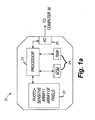
- Fig. 1 illustrates a dental x-ray system 10.
- the system includes an x-ray source 12.
- the source is located on an end 13 of a mechanical arm 15.
- the x-ray source 12 When activated, the x-ray source 12 generates an x-ray stream 16 that has a generally circular cross-section.
- a collimator is used to reduce the size of the stream and generate a smaller x-ray stream having a rectangular cross-section.
- a collimator may be used with a mechanical positioning device to help align the x-ray stream with an x-ray sensor. As shown in Fig.
- the arm 15 is positioned (e.g., by an operator) so that the x-ray stream is directed to an intraoral sensor 20.
- the intraoral sensor 20 is shown located in the mouth of a patient 21.
- the intraoral sensor 20 includes a scintillator that coverts x-ray radiation to visible light.
- the sensor 20 is configured to convert x-rays to electrons without a scintillator.
- the sensor 20 also includes an array of pixels 22. Each pixel produces an electric signal in response to light (from the scintillator) or x-ray radiation impinged upon it.
- the senor 20 includes one or more "on-board" analog-to-digital converters to covert analog signals generated by the pixels to digital signals. These signals are provided to a processor 23 (such as a programmable, electronic microprocessor or similar device). In the embodiment shown, the processor 23 is connected to memory 24 (ROM and RAM) and an input-output interface 25. The sensor also includes one or more electronic circuits for power supply, driving the array of pixels, and driving the output (e.g., circuits located in the I/O interface 25). As discussed in greater detail below, in the embodiment illustrated, the processor 23 controls image capture or triggering of the sensor 20.
- a processor 23 such as a programmable, electronic microprocessor or similar device.
- the processor 23 is connected to memory 24 (ROM and RAM) and an input-output interface 25.
- the sensor also includes one or more electronic circuits for power supply, driving the array of pixels, and driving the output (e.g., circuits located in the I/O interface 25).
- the processor 23 controls image capture or
- a wire, cable, or similar connecter 27 of the sensor 20 connects the sensor 20 to a computer 30.
- the computer 30 includes various components, including a processor or similar electronic device 32, an input/output interface 34, and memory 36 (e.g., RAM and ROM).
- the input/output interface 34 is a USB connection and the connector 27 is a USB cable.
- Fig. 1 illustrates that image data captured by the sensor 20 and processed by the computer 30 is sent to a display 38 and viewed as image 40. (Image 40 is drawn more distinctly than an x-ray image would typically appear.)
- the location of the intraoral sensor 20 in the patient's mouth determines what part of the patient's anatomy can be imaged (e.g., the upper jaw versus the lower jaw or the incisors versus the molars.)
- An x-ray operator places (or assists the patient in placing) the intraoral sensor at a desired location with the patient's mouth.
- Various sensor holders may be used to keep the sensor 20 in the desired location until an image is created or captured. For example, some holders are designed so that the patient bites the holder with his or her teeth and maintain the position of the sensor by maintaining a bite on the holder.
- the sensor After the sensor is positioned behind the desired anatomical structure, and the x-ray field to be generated by the x-ray source 12 is aligned with the sensor, it is possible that the source and sensor will, nevertheless, become misaligned. Misalignment can be caused by the patient moving his or her head, moving the intraoral sensor (by re-biting the holder, moving his or her tongue, etc.), and other causes.
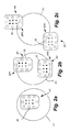
- Fig. 2a illustrates an alignment A1 in which the sensor 20 is located entirely within an x-ray field F1 produced by the x-ray source 12.
- Fig. 2b illustrates two alignments A2 and A3, where the sensor 20 is located mostly within the x-ray field F1, but a portions of the sensor (either SP1 or SP2) are located outside of the field F1.
- Fig. 2c illustrates two alignments A4 and A5, where the sensor 20 is located mostly outside the x-ray field F1, but portions (either SP3 or SP4) are located inside of the field F1.
- image capture is triggered based on manual activation of a switch or upon the output of an image sensor (i.e., the output from all the pixels) exceeding a predetermined threshold.
- triggering of image capture or acquisition is based on sub-sampling particular pixel clusters located within an image sensor.
- Fig. 3a illustrates the alignment of pixels in the sensor 20.
- the sensor 20 includes a plurality of pixels and the processor 23 receives information from the pixels.
- the processor reads out data from the pixels in the array of pixels of the sensor.
- Fig. 3a illustrates eight lines of pixels of the sensor (lines 52, 54, 56, 58, 60, 62, 64, and 66.)
- Each line includes a first cluster of pixels and a second cluster of pixels.
- line 52 includes clusters 70 and 71.
- Line 54 includes clusters 72 and 73.
- Lines 56, 58, 60, 62, 64, and 66 include clusters 74 and 75, 76 and 77, 78 and 79, 80 and 81, 82 and 83, and 84 and 85, respectively.
- each pixel cluster 70-85 includes 32 pixels.
- Each of the pixel clusters in each line of the array of pixels is located at the edge or perimeter P or the sensor.
- each of the pixel clusters on the left-hand side (“LHS") of the sensor 20 i.e., clusters 72, 74, 76, 78, 80, 82, and 84
- LHS left-hand side
- RHS right-hand side
- the pixel clusters in each of the lines of pixels and in the general configuration shown in Fig. 3a are referred to as the "perimeter pixels.”
- the processor 23 carries out a rolling-shutter mode scanning of the perimeter pixels.
- the pixel integration time is set at a predetermined amount and one cluster is sampled at some fraction of this time.
- the integration time could be set between 5 to 50 milliseconds with the scanning or sampling time being a corresponding lower amount.
- the integration time is 16 milliseconds (ms) and one cluster is sampled every 1 ms.
- cluster 70 in line 52 is sampled and approximately 1 ms later the pixel cluster 71 in the same line (line 54) is sampled, this process continues until all the clusters in the eight lines are read or sampled. Reading is carried out in a destructive manner, meaning that once the information is readout of a pixel, the pixel is reset.
- the signal in a pixel includes two main portions: a background signal and a signal generated as a result of incident x-ray radiation.
- the background signal is mostly a consequence of 1) "dark current” (a generally unavoidable disturbance that depends on temperature), 2) other parameters, and 3) noise.
- a signal conditioning technique called double sampling or correlated double sampling (“DS/CDS") is used to improve the ratio between the signal and background noise. If DS/CDS is used, the pixel's signal is read (the "initial pixel reading"), then the pixel is reset and the reset level is read and subtracted from the initial pixel reading. This methodology helps cancel read-out noise.
- DS/CDS is performed on the same chip on which the array of pixels is constructed. The analog values are subtracted and only then converted to a digital signal by an analog-to-digital converter.
- the values from each pixel in a pixel cluster are combined.
- the combined value is evaluated against a predetermined threshold. If the combined value exceeds the threshold, image acquisition is triggered.
- the way in which values from the pixels are combined can vary but certain techniques for doing so are described below.
- the signal-to-noise ("SNR") ratio of the combined values is relatively low.
- combination of the pixel values is carried out in a manner that improves the SNR.
- the pixel values are integrated. Signals from the pixels are correlated from pixel to pixel and the integration is performed by adding the values. Because the values are correlated from pixel to pixel, when the values are added to each other, noise is averaged out.
- the threshold to which the combination or sum of values is compared to is (in one embodiment), a predetermined threshold based on empirical knowledge.
- the threshold may be a few millivolts or correlated to an x-ray dose of a few ⁇ Gy (e.g., 5 ⁇ Gy).
- the threshold is determined using an adaptive technique that takes into account temperature, dark current, or both.
- the sensor 20 is always armed (or turned on). When the sensor is so configured, it will detect x-ray radiation without requiring that the operator activate it.
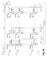
- Fig. 3b depicts an exemplary diagram of the array of pixels 22.
- the array of pixels 22 is depicted as an N x M pixel array for explanation purposes; the values of N and M may vary depending on the implementation.
- the array of pixels 22 includes pixels 86, a reset switch 87, and a sensing switch 88.
- Each pixel includes a reset/sense switch 89, an integrating element 90, a read-out amplifier 91, and a read-out switch 92.
- the integrating element 90 integrates charge in response to receiving energy based on x-rays, dark current, and noise, as will be described in more detail below. While we use the term charge in this description, broadly speaking, the charge represents the amount of energy received at the integrating element 90.
- electrons, holes, or other electrical signals represent the amount of energy received at the integrating element 90.
- Each pixel also receives one of the row select lines 93 and column select lines 94.
- the row select line 93 controls the read-out switch 92.
- the charge stored on each integrating element 90 is read using the appropriate row select line 93 and column select line 94 and interpreted to generate an x-ray image 40 as described above.
- the integrating element 90 is erased upon a read out (a "destructive" read). In some embodiments, it is possible for the integrating element 90 to be read out and not erased (a "non-destructive" read), and periodically resetting all or a portion of the array of pixels 22 instead.
- the array of pixels 22 has four general function states: 1) a reset state, 2) a detecting state, 3) an integrating state, and 4) a read-out state.
- the reset state the charge stored on the integrating element 90 of each pixel 86 is removed by setting the integrating elements 90 to the reference voltage (e.g., 2 volts).
- the integrating elements 90 are set to the reference voltage by closing the reset/sense switch 89 and the reset switch 87, while leaving the sensing switch 88 and read-out switch 92 open.
- each integrating element 90 begins with a voltage approximately equal to the reference voltage from the reset state. Thereafter, as charge is integrating at the integrating element 90 from x-ray energy, dark current, and noise, the voltage at the integrating element 90 decreases.
- the collective voltage of the particular pixels selected (referred to as the "diode voltage," since a group of pixels selected can be viewed as a meta diode) measured across the sensing line 98 and ground 99 decreases as the voltage at any integrating element 90 decreases.
- the sensing switch 88 and the appropriate row select line 93 and column select line 94 are enabled to couple the appropriate pixels 86 to the sensing line 98.
- sense cluster 70 1) row select line 1 is enabled; and 2) column select lines 1-32 are enabled (cluster 70).
- row select line 2 is enabled, and the same column select lines remain enabled from sensing cluster 70 (i.e., column select lines 1-32 are enabled).
- row select line 1 is enabled, and column select lines column select lines M to M-32 are enabled.
- additional sensing switches 88 are provided in the array of pixels 22.
- Each sensing switch 88 is connected to a particular portion of pixels 42 (e.g., one of the pixel rows 52-66) and each sensing switch 88 is associated with its own diode voltage. Thus, multiple pixel clusters 70-85 are sensed simultaneously by sensing the diode voltage of each sense switch, as opposed to cycling through the pixel rows 70-85 one-by-one.
- all switches (87, 88, 89, and 92) are open.
- the array of pixels 22 integrates the charges created by the x-ray radiation as well as by the undesirable noise components (e.g., dark current).
- a signal is provided to a column select line 94 (one from column select lines 1 through M).
- a signal is provided along a row select line 93 (one from row select lines 1 through N).
- the read-out switches of the selected row of pixels is closed.
- the charge stored on the integrating elements 90 of the row of pixels is output along the output paths 96.
- the indication provided to the particular column select line 94 serves to chose one of the output paths 96 and allows the charge output along the chosen output path 96 to be input to the A/D converter 97.
- the A/D converter 97 converts the analog signal received from a pixel and outputs a digital signal to the processor 23.
- multiple pixels are read out in parallel.
- the A/D converter 97 converts multiple analog signals from pixels 86 to digital signals simultaneously and forwards the digital signals along a multi-bit bus to the processor 23.
- individual pixel A/D converters are provided within each pixel, as opposed to a single A/D converter 97.
- the charge integrating on integrating elements 90 increases (rather than decreases) the voltage stored across each integrating element.
- the reset signal removes the stored charge on each integrating element 90 by causing the voltage across each integrating element 90 to be set to ground.
- the diode voltage increases, rather than decreases, as the array of pixels is exposed to x-ray radiation, dark current, and other noise.
- the threshold voltage is set to a value above the reset value and is crossed upon the diode voltage increasing to a level above the threshold.
- a variation of the pixel-cluster scanning technique described above is implemented.
- all of the pixel clusters are read or scanned at the same speed.
- one group of pixel clusters is read quickly (or fast) (e.g., every millisecond) and the second group of pixel clusters is read slowly (or slow) (e.g., every 10 ms).
- Both sets of clusters are assigned thresholds (which can be different).
- the clusters of pixels are located in the same positions as the clusters of perimeter pixels discussed above. However, it is possible that the location of pixel clusters could be different in embodiments that utilize multiple reading speeds.
- Fig. 4a includes a graph 100. Time is measured on the horizontal axis, X, and signal magnitude is measured on the vertical axis, Y.
- Fig. 4a illustrates an embodiment with a first, relatively short reset time T1.
- dark current is the relatively small electric current that flows through photosensitive devices even when the device is not energized by radiation. Changes in temperature can affect dark current.
- the dark signal curve, DS in Fig. 4a , the magnitude of the pixel or sensor signal due to dark current increases over time. The pixels are periodically reset (e.g., every T1 milliseconds) to remove the dark signal.
- the dark signal alone could reach a level that meets or exceeds a sensor trigger threshold, TT1.
- a sensor trigger threshold TT1
- Two circumstances are illustrated in Fig 4a .
- the sum of a dark signal 110 and an x-ray signal 112 (the signals 110 and 112 are shown overlapping one another, not added to one another) exceeds the threshold TT1.
- the sum of a dark signal 114 and an x-ray signal 116 does not exceed the threshold TT1.
- Fig. 4b illustrates a graph 150 with similar axes (X' and Y') as in Fig. 4a ., but a relatively long reset time T2. Like Fig. 4a, Fig. 4b illustrates two circumstances. One in which the sum of a dark signal 154 and an x-ray signal 156 exceeds a trigger threshold TT2 and a second in which the sum of a dark signal 160 and an x-ray signal 164 does not exceed the threshold TT2.
- x-ray doses can vary due to a variety of reasons. Reading certain groups of pixels at different speeds helps compensate for these differences and to adapt to different dose rates.
- a fast read time is used.
- the reset time for the pixels is set to a relatively short time. Having a short reset time is particularly useful when the x-ray source is a high dose or high dose rate source, the distance between the x-ray source and the sensor is short, or both. Reducing the reset time helps reduce the possibility of false triggers.
- a short reset time is prudent only when the x-ray signal is relatively strong, as the fast reset time tends to reduce the contribution of the dark signal in the sum of the dark signal and x-ray signal, which as noted above, is the value that is compared to the triggering threshold.
- a slow read time is used.
- the reset time for the pixels is set to a relatively long time. Having a long reset time is particularly useful when the x-ray source is a low dose source or low dose rate source, the distance between the x-ray source and the sensor is long, or both. Increasing the reset time is prudent when the x-ray signal is relatively low, as the long reset time increases the contribution of the dark signal in the sum of the dark signal and x-ray signal. The increased read time comes at the expense of a lower or slower image detection speed.
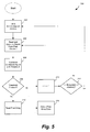
- Fig. 5 depicts a process 200 for automatically triggering the sensor 20 to capture an image.
- step 202 also includes resetting the array of pixels 22 to remove any dark current, noise, or other undesirable integrated charge using reset switch 87.
- the pixel cluster i e.g., cluster 0
- cluster 0 is shown as cluster 70.
- processor 23 compares the signal value read from cluster i with a threshold (e.g., threshold TT1 or TT2).
- a threshold e.g., threshold TT1 or TT2
- step 208 if the comparison indicates that the threshold has not been crossed, the processor 23 proceeds to step 210 and increments the parameter i.
- delay counters or similar techniques are incorporated in the process 200.
- the processor 23 is operable to delay the pixel reading step 204 until a predetermined time has passed since the previous execution of step 204.
- process 200 is altered to include nested loops to achieve different cycle times for particular pixel clusters.
- the nested loops use particular delay times, particular increment values in step 210, or a combination thereof to achieve the desired cycle time for pixel clusters.
- the invention provides, among other things, automatic triggering of an x-ray sensor using a selected group of pixels.
- the trigger threshold is adapted so that the onset of x-rays will be detected even in very low-dose conditions.
- the sensor was successfully triggered both with 480 ⁇ Gy/s dose rates and with a total dose of 5 ⁇ Gy.
- the SNR of the signal created by the sensor is adapted (because the overall sensor signal is low, but the sum of the noise is constant).
- the trigger level is stable and does not require adjustments to accommodate for time-dependent effects like accumulating dark signal.
Landscapes
- Health & Medical Sciences (AREA)
- Life Sciences & Earth Sciences (AREA)
- Engineering & Computer Science (AREA)
- Medical Informatics (AREA)
- Physics & Mathematics (AREA)
- General Health & Medical Sciences (AREA)
- Molecular Biology (AREA)
- Heart & Thoracic Surgery (AREA)
- Nuclear Medicine, Radiotherapy & Molecular Imaging (AREA)
- Optics & Photonics (AREA)
- Pathology (AREA)
- Radiology & Medical Imaging (AREA)
- Biomedical Technology (AREA)
- Veterinary Medicine (AREA)
- Biophysics (AREA)
- Surgery (AREA)
- Animal Behavior & Ethology (AREA)
- High Energy & Nuclear Physics (AREA)
- Public Health (AREA)
- Oral & Maxillofacial Surgery (AREA)
- Computer Vision & Pattern Recognition (AREA)
- Mathematical Physics (AREA)
- Multimedia (AREA)
- Signal Processing (AREA)
- Dentistry (AREA)
- General Physics & Mathematics (AREA)
- Electromagnetism (AREA)
- Apparatus For Radiation Diagnosis (AREA)
Claims (22)
- Intraorales Röntgensystem, das Folgendes umfasst:einen intraoralen Sensor, der eine Anordnung von Pixeln aufweist, wobei die Anordnung von Pixeln eine Vielzahl von Pixelclustern aufweist, wobei jedes der Pixel ein elektrisches Signal erzeugt, das mit einer Röntgenstrahlung korreliert ist, die auf das Pixel trifft; undeine elektronische Steuereinheit, die mit der Anordnung von Pixeln verbunden ist, um elektrische Signale von der Anordnung von Pixeln zu empfangen und jedes Pixelcluster zu lesen, wobei die elektronische Steuereinheit für Folgendes konfiguriert ist: Erzeugen eines kombinierten Signals für jedes Pixelcluster und Initiieren der Erfassung eines Bildes, das mit Hilfe von Informationen von jedem der Pixel in der Anordnung von Pixeln erzeugt wurde, die einer Strahlung ausgesetzt sind, wenn mindestens eines der kombinierten Signale einen vorbestimmten Grenzwert überschreitet.
- Röntgensystem nach Anspruch 1, wobei die elektronische Steuereinheit ferner dafür konfiguriert ist, eine Pixelintegration durchzuführen.
- Röntgensystem nach Anspruch 1, wobei die Pixelintegration innerhalb einer vorbestimmten Zeitspanne durchgeführt wird und Lesen jedes der Pixelcluster in einem Bruchteil der vorbestimmten Zeitspanne.
- Röntgensystem nach Anspruch 1, wobei die elektronische Steuereinheit ferner dafür konfiguriert ist, Signale von den Pixeln auf einer Pixel-zu-Pixel-Basis zu korrelieren.
- Röntgensystem nach Anspruch 1, wobei die elektronische Steuereinheit ferner dafür konfiguriert ist, die Pixelcluster im Rolladenmodus abzutasten.
- Röntgensystem nach Anspruch 1, wobei die Pixelcluster erste Pixelcluster und zweite Pixelcluster umfassen und wobei jedes erste Pixelcluster eine vorbestimmte Anzahl von Pixeln auf einer linken Seite der Anordnung von Pixeln in mindestens einer linken Gruppe von Pixeln umfasst und jedes zweite Pixelcluster eine vorbestimmte Anzahl von Pixeln auf einer rechten Seite der Anordnung von Pixeln in mindestens einer rechten Gruppe von Pixeln umfasst.
- Röntgensystem nach Anspruch 1, wobei die elektronische Steuereinheit mindestens eine von zwei Arten der Signalkonditionierung durchführt: Doppelabtastung und korrelierte Doppelabtastung.
- Röntgensystem nach Anspruch 1, wobei der vorbestimmte Grenzwert mindestens eines von Folgendem umfasst: (a) einen empirischen Grenzwert; und (b) einen Grenzwert, der mit Hilfe eines adaptiven Verfahrens bestimmt wird.
- Röntgensystem nach Anspruch 1, wobei sich die Pixelcluster benachbart zu einem Umfang der Anordnung von Pixeln befinden.
- Röntgensystem nach Anspruch 1, wobei die elektronische Steuereinheit jedes Pixelcluster destruktiv liest.
- Röntgensystem nach Anspruch 1, wobei die elektronische Steuereinheit die Pixelcluster jeweils einzeln nacheinander liest.
- Verfahren zum automatischen Auslösen eines intraoralen Röntgensensors zur Erfassung eines Bildes, wobei der intraorale Sensor eine Anordnung von Pixeln aufweist, wobei die Anordnung von Pixeln eine Vielzahl von Pixelclustern aufweist und das Verfahren Folgendes umfasst:Richten einer Röntgenstrahlung in Richtung des intraoralen Sensors;wenn die Röntgenstrahlung auf ein Pixel in der Anordnung von Pixeln trifft, Erzeugen eines elektrischen Signals, das mit der Röntgenstrahlung korreliert ist, die auf das Pixel trifft;Verarbeiten elektrischer Signale, die durch ein oder mehrere Pixel in der Anordnung von Pixeln in einer elektronischen Steuereinheit durch Lesen der Pixelcluster erzeugt werden;Erzeugen eines kombinierten Signals für jedes Pixelcluster basierend auf den Signalen von jedem der Pixelcluster; undwenn mindestens eines der kombinierten Signale einen vorbestimmten Grenzwert überschreitet: Initiieren der Erfassung des Bildes, das mit Hilfe von Informationen von jedem der Pixel in der Anordnung von Pixeln erzeugt wurde, die der Strahlung ausgesetzt wird.
- Verfahren nach Anspruch 12, das ferner das Integrieren von Werten von Pixeln in den Pixelclustern umfasst.
- Verfahren nach Anspruch 12, das ferner das Lesen der Pixelcluster in einem Rolladenmodus umfasst.
- Verfahren nach Anspruch 12, wobei das Verfahren ferner Folgendes umfasst: Durchführen der Pixelintegration innerhalb einer vorbestimmten Zeitspanne und Lesen jedes der Pixelcluster in einem Bruchteil der vorbestimmten Zeitspanne.
- Verfahren nach Anspruch 12, das ferner das Korrelieren von Signalen von den Pixeln auf einer Pixel-zu-Pixel-Basis umfasst.
- Verfahren nach Anspruch 12, wobei die Pixelcluster erste Pixelcluster und zweite Pixelcluster umfassen und wobei jedes erste Pixelcluster eine vorbestimmte Anzahl von Pixeln auf einer linken Seite der Anordnung von Pixeln in mindestens einer linken Gruppe von Pixeln umfasst und jedes zweite Pixelcluster eine vorbestimmte Anzahl von Pixeln auf einer rechten Seite der Anordnung von Pixeln in mindestens einer rechten Gruppe von Pixeln umfasst.
- Verfahren nach Anspruch 12, das ferner das Durchführen von mindestens einer von zwei Arten der Signalkonditionierung umfasst: Doppelabtastung und korrelierte Doppelabtastung.
- Verfahren nach Anspruch 12, das ferner mindestens einen der folgenden Schritte umfasst: (a) Bestimmen des vorbestimmten Grenzwerts basierend auf empirischen Informationen; und (b) Bestimmen des vorbestimmten Grenzwerts mittels eines adaptiven Verfahrens.
- Verfahren nach Anspruch 12, wobei sich jedes der Pixelcluster benachbart zu einem Umfang der Anordnung von Pixeln befindet.
- Verfahren nach Anspruch 12, wobei jedes der Pixelcluster von der elektronischen Steuereinheit destruktiv gelesen wird.
- Verfahren nach Anspruch 12, wobei jedes der Pixelcluster von der elektronischen Steuereinheit nacheinander gelesen wird.
Applications Claiming Priority (3)
| Application Number | Priority Date | Filing Date | Title |
|---|---|---|---|
| US22653309P | 2009-07-17 | 2009-07-17 | |
| US12/796,235 US9492129B2 (en) | 2008-10-27 | 2010-06-08 | Triggering of intraoral X-ray sensor using pixel array sub-sampling |
| PCT/US2010/039322 WO2011008421A1 (en) | 2009-07-17 | 2010-06-21 | Triggering of intraoral x-ray sensor using pixel array sub-sampling |
Publications (3)
| Publication Number | Publication Date |
|---|---|
| EP2453799A1 EP2453799A1 (de) | 2012-05-23 |
| EP2453799A4 EP2453799A4 (de) | 2013-01-23 |
| EP2453799B1 true EP2453799B1 (de) | 2015-04-08 |
Family
ID=43449672
Family Applications (1)
| Application Number | Title | Priority Date | Filing Date |
|---|---|---|---|
| EP10800232.0A Not-in-force EP2453799B1 (de) | 2009-07-17 | 2010-06-21 | Auslösen eines intraoralen röntgenstrahlsensors unter verwendung einer pixel-anordnungs-unterprobennahme |
Country Status (6)
| Country | Link |
|---|---|
| US (2) | US9492129B2 (de) |
| EP (1) | EP2453799B1 (de) |
| JP (2) | JP2012533339A (de) |
| KR (1) | KR101749777B1 (de) |
| CN (1) | CN102481135B (de) |
| WO (1) | WO2011008421A1 (de) |
Families Citing this family (23)
| Publication number | Priority date | Publication date | Assignee | Title |
|---|---|---|---|---|
| US9492129B2 (en) | 2008-10-27 | 2016-11-15 | Dental Imaging Technologies Corporation | Triggering of intraoral X-ray sensor using pixel array sub-sampling |
| US8366318B2 (en) | 2009-07-17 | 2013-02-05 | Dental Imaging Technologies Corporation | Intraoral X-ray sensor with embedded standard computer interface |
| JP2013012888A (ja) * | 2011-06-29 | 2013-01-17 | Canon Inc | 撮影装置、撮影システム、制御装置、イメージセンサの制御方法 |
| JP5512638B2 (ja) | 2011-11-22 | 2014-06-04 | 富士フイルム株式会社 | 放射線画像検出装置及び放射線撮影システム |
| JP2014048204A (ja) | 2012-08-31 | 2014-03-17 | Canon Inc | 放射線撮像装置及び放射線撮像システム |
| US9470008B2 (en) * | 2013-12-12 | 2016-10-18 | Crystal Lagoons (Curacao) B.V. | System and method for maintaining water quality in large water bodies |
| EP3148439B1 (de) * | 2014-05-27 | 2020-11-04 | Agfa Nv | Verfahren zur steuerung von mehreren drahtlosen selbstauslösenden radiographischen bildsensoren in einer einzigen belichtung |
| RU2614984C2 (ru) * | 2014-07-03 | 2017-04-03 | Закрытое акционерное общество "Научно-исследовательская производственная компания "Электрон" (ЗАО НИПК "Электрон") | Система формирования изображения для рентгенодиагностического комплекса и рентгенодиагностический комплекс |
| CN105794195B (zh) * | 2014-10-27 | 2020-02-07 | 松下知识产权经营株式会社 | 图像形成系统、图像形成方法以及拍摄元件 |
| FR3032105B1 (fr) | 2015-01-30 | 2017-01-27 | E2V Semiconductors | Capteur radiologique avec detection de rayons x |
| KR102377484B1 (ko) * | 2015-04-20 | 2022-03-22 | 주식회사 바텍 | 모션 센서를 구비한 엑스선 조사 장치 및 이를 이용한 엑스선 촬영 방법 |
| JP5925937B2 (ja) * | 2015-04-24 | 2016-05-25 | 富士フイルム株式会社 | 放射線の照射開始判定装置およびその作動方法、並びに放射線の照射開始判定システム |
| KR101676426B1 (ko) * | 2015-07-02 | 2016-11-15 | 주식회사 디알텍 | 방사선 디텍터 및 이를 이용한 방사선 촬영방법 |
| JP6668717B2 (ja) | 2015-12-04 | 2020-03-18 | コニカミノルタ株式会社 | 放射線撮影装置及び放射線撮影システム |
| JP6093069B2 (ja) * | 2016-04-19 | 2017-03-08 | 富士フイルム株式会社 | 放射線の照射開始判定装置およびその作動方法、並びに放射線の照射開始判定システム |
| US10932733B2 (en) | 2016-09-14 | 2021-03-02 | Dental Imaging Technologies Corporation | Multiple-dimension imaging sensor with operation based on movement detection |
| US10213180B2 (en) * | 2016-09-14 | 2019-02-26 | Dental Imaging Technologies Corporation | Multiple-dimension imaging sensor with operation based on magnetic field detection |
| KR101997826B1 (ko) * | 2017-11-15 | 2019-07-08 | (주)해우기술 | 엑스레이 디텍터 제어장치 및 그 방법 |
| US10441509B2 (en) * | 2018-03-16 | 2019-10-15 | Berkshire Biomedical, LLC | Computerized oral prescription administration with refillable medication dispensing devices and associated systems and methods |
| EP3673810B1 (de) | 2018-12-28 | 2023-09-27 | Sirona Dental Systems GmbH | Dentales röntgenbildgebungssystem zur erzeugung von intraoralen röntgenbildern |
| US11911197B2 (en) * | 2021-12-14 | 2024-02-27 | BAE Systems Imaging Solutions Inc. | X-ray sensor system for intraoral tomography |
| US12015870B2 (en) * | 2022-08-03 | 2024-06-18 | BAE Systems Imaging Solutions Inc. | X-ray onset detector for intraoral dental sensor |
| KR102843067B1 (ko) * | 2025-01-02 | 2025-08-06 | (주)비트리 | 트리거 기반의 구강 방사선 영상 획득 방법, 장치 및 프로그램 |
Family Cites Families (126)
| Publication number | Priority date | Publication date | Assignee | Title |
|---|---|---|---|---|
| US3023267A (en) * | 1959-03-05 | 1962-02-27 | Gen Cable Corp | Combination power and communication cable |
| US3843831A (en) * | 1973-04-30 | 1974-10-22 | Belden Corp | Low capacitance and low leakage cable |
| DE2519640C3 (de) | 1975-05-02 | 1981-02-05 | Siemens Ag, 1000 Berlin Und 8000 Muenchen | Dental-Röntgendiagnostikeinrichtung mit Mitteln zur Bemessung der Aufnahmezeit |
| US4057732A (en) * | 1976-02-04 | 1977-11-08 | Rolf Marcus Klauser | Film holder for bite-wing radiographs |
| US4259583A (en) * | 1979-05-03 | 1981-03-31 | Albert Richard D | Image region selector for a scanning X-ray system |
| FR2547495B1 (fr) * | 1983-06-16 | 1986-10-24 | Mouyen Francis | Appareil permettant d'obtenir une image radiologique dentaire |
| US4866750A (en) * | 1987-03-27 | 1989-09-12 | Board Of Regents, The University Of Texas System | Image receptor holder and bite block device |
| JPH02101878A (ja) * | 1988-10-11 | 1990-04-13 | Nec Corp | 固体撮像装置 |
| DE8909398U1 (de) | 1989-08-03 | 1989-10-05 | Siemens AG, 1000 Berlin und 8000 München | Zahnärztliche Röntgendiagnostikeinrichtung |
| SE469104B (sv) | 1991-06-03 | 1993-05-10 | Regam Medical Systems Ab | Foerfarande och anordning vid roentgenapparat med elektronisk bildavkaenning |
| US5220130A (en) * | 1991-08-06 | 1993-06-15 | Cooper Industries, Inc. | Dual insulated data cable |
| US5331166A (en) * | 1991-10-25 | 1994-07-19 | Kabushiki Kaisha Morita Seisakusho | Dental X-ray image detecting device with an automatic exposure function |
| DE4218020C1 (de) * | 1992-06-01 | 1993-07-15 | Siemens Ag, 8000 Muenchen, De | |
| JPH08603Y2 (ja) | 1992-07-02 | 1996-01-10 | 株式会社新来島どっく | 風向指向型排ガス管吹出構造 |
| JP3190458B2 (ja) * | 1992-10-15 | 2001-07-23 | 浜松ホトニクス株式会社 | 歯科用x線画像処理装置 |
| US5434418A (en) * | 1992-10-16 | 1995-07-18 | Schick; David | Intra-oral sensor for computer aided radiography |
| US5436476A (en) * | 1993-04-14 | 1995-07-25 | Texas Instruments Incorporated | CCD image sensor with active transistor pixel |
| US5572566A (en) | 1993-11-30 | 1996-11-05 | J. Morita Manufacturing Corporation | X-ray imaging apparatus and X-ray generation detector for activating the same |
| DE4402114C2 (de) * | 1994-01-25 | 1999-06-02 | Sirona Dental Systems Gmbh | Strahlendetektor mit einem Gehäuse zur Aufnahme eines Strahlungswandlers |
| US5471515A (en) * | 1994-01-28 | 1995-11-28 | California Institute Of Technology | Active pixel sensor with intra-pixel charge transfer |
| US5444756A (en) * | 1994-02-09 | 1995-08-22 | Minnesota Mining And Manufacturing Company | X-ray machine, solid state radiation detector and method for reading radiation detection information |
| US5574250A (en) * | 1995-02-03 | 1996-11-12 | W. L. Gore & Associates, Inc. | Multiple differential pair cable |
| US5757011A (en) * | 1995-02-10 | 1998-05-26 | Orbit Semiconductor, Inc. | X-ray onset detector and method |
| US5510623A (en) * | 1995-02-24 | 1996-04-23 | Loral Fairchild Corp. | Center readout intra-oral image sensor |
| DE29505854U1 (de) * | 1995-04-05 | 1995-06-01 | Pfeiffer, Manfred, Dr., London | Gerät zur Bilderfassung im Oralbereich, insbesondere zur zahnmedizinischen Diagnose |
| SE9501332L (sv) | 1995-04-10 | 1996-10-11 | Regam Medical Systems Ab | Anordning vid CCD-cell |
| DE29506839U1 (de) * | 1995-04-22 | 1995-06-22 | Pfeiffer, Manfred, Dr., London | Intraoral eines Patientenmundes plazierbarer Sensor zur Erstellung von Zahn-/Kieferaufnahmen eines Patienten |
| GB2303772B (en) | 1995-07-28 | 1999-06-16 | Eev Ltd | Imaging apparatus |
| CN1156376A (zh) | 1995-08-01 | 1997-08-06 | Eev有限公司 | 成像设备 |
| GB9515762D0 (en) * | 1995-08-01 | 1995-10-04 | Eev Ltd | Imaging apparatus |
| JP3441578B2 (ja) * | 1995-11-22 | 2003-09-02 | 株式会社モリタ製作所 | 歯科用パノラマx線撮影装置 |
| US6271880B1 (en) | 1996-02-26 | 2001-08-07 | Canon Kabushiki Kaisha | Apparatus having a photoelectric conversion element and a transistor, in which the duration of the on time of the transistor is based on a detected temperature of the conversion element or transistor |
| US6127684A (en) | 1996-02-26 | 2000-10-03 | Canon Kabushiki Kaisha | Photoelectric conversion apparatus and driving method of the apparatus |
| US5789711A (en) * | 1996-04-09 | 1998-08-04 | Belden Wire & Cable Company | High-performance data cable |
| US5887049A (en) * | 1996-11-12 | 1999-03-23 | California Institute Of Technology | Self-triggered X-ray sensor |
| US6011251A (en) * | 1997-06-04 | 2000-01-04 | Imec | Method for obtaining a high dynamic range read-out signal of a CMOS-based pixel structure and such CMOS-based pixel structure |
| JPH10277028A (ja) * | 1997-04-08 | 1998-10-20 | Morita Mfg Co Ltd | 歯科用x線画像検出器およびそのアダプタ |
| JP3836208B2 (ja) * | 1997-04-09 | 2006-10-25 | 浜松ホトニクス株式会社 | 医療用小型x線画像検出装置 |
| US6074503A (en) * | 1997-04-22 | 2000-06-13 | Cable Design Technologies, Inc. | Making enhanced data cable with cross-twist cabled core profile |
| US5912942A (en) * | 1997-06-06 | 1999-06-15 | Schick Technologies, Inc. | X-ray detection system using active pixel sensors |
| DE29717432U1 (de) * | 1997-09-30 | 1999-02-04 | Sirona Dental Systems GmbH & Co. KG, 64625 Bensheim | Intraoral eines Patientenmundes plazierbarer Sensor zur Erstellung von Zahn-/Kieferaufnahmen eines Patienten |
| TW410516B (en) * | 1998-07-28 | 2000-11-01 | Novatek Microelectronics Corp | Electromagnetic safety enhancement device for universal serial bus and method thereof |
| US6462268B1 (en) * | 1998-08-06 | 2002-10-08 | Krone, Inc. | Cable with twisting filler and shared sheath |
| US6134298A (en) * | 1998-08-07 | 2000-10-17 | Schick Technologies, Inc. | Filmless dental radiography system using universal serial bus port |
| US6033111A (en) * | 1998-11-20 | 2000-03-07 | Wolf X-Ray Corporation | Color coding method and apparatus for an X-ray positioning system |
| EP1131916B1 (de) * | 1998-11-24 | 2006-02-08 | Giga A/S | Verfahren und schaltung zur neutaktung eines digitalen datensignals |
| JP2000175906A (ja) | 1998-12-18 | 2000-06-27 | Matsushita Electric Ind Co Ltd | パノラマx線撮影装置 |
| US6203195B1 (en) * | 1999-01-20 | 2001-03-20 | Timothy G. Willis | Holder for dental sensors |
| AU4600600A (en) * | 1999-04-26 | 2000-11-10 | Simage Oy | Self triggered imaging device for imaging radiation |
| EP1194811B1 (de) * | 1999-06-30 | 2004-05-12 | Dentsply International, Inc. | Positioniervorrichtung für verschiedene dentale Röntgenaufnahmeverfahren mit einer Sensorhalterung und unterschiedlichen Bi blöcken modularen Designs |
| US7081607B1 (en) * | 1999-10-05 | 2006-07-25 | Canon Kabushiki Kaisha | Solid state image pickup device and image pickup system |
| US6244866B1 (en) * | 1999-12-29 | 2001-06-12 | Regina Campbell | Tongue suppressing bite block |
| WO2001058148A1 (en) | 2000-02-02 | 2001-08-09 | Dentsply International Inc. | Automatic x-ray detection for intra-oral dental x-ray imaging apparatus |
| JP4234304B2 (ja) * | 2000-05-19 | 2009-03-04 | 浜松ホトニクス株式会社 | 放射線検出器 |
| JP4398065B2 (ja) * | 2000-05-19 | 2010-01-13 | 浜松ホトニクス株式会社 | 放射線検出器 |
| US6527442B2 (en) * | 2000-06-26 | 2003-03-04 | Afp Imaging Corporation | Integrated sensor holder for dental imaging |
| US6307915B1 (en) * | 2000-06-26 | 2001-10-23 | Afp Imaging Corporation | Triggering of solid state X-ray imagers with non-destructive readout capability |
| US6404854B1 (en) * | 2000-06-26 | 2002-06-11 | Afp Imaging Corporation | Dental x-ray imaging system |
| US6320934B1 (en) * | 2000-06-26 | 2001-11-20 | Afp Imaging Corporation | Sensor characterization in memory |
| DE20100641U1 (de) | 2001-01-27 | 2001-07-26 | Herzog, Rainer, Dipl.-Ing.Univ., 90537 Feucht | Universell verstellbares Halter-System zur einfachen Positionierung eines Aufnahmemediums bei Röntgenaufnahmen |
| SE0100382D0 (sv) | 2001-02-07 | 2001-02-07 | Lp Roentgenteknik Ab | X-ray detector |
| DE50106886D1 (de) | 2001-05-05 | 2005-09-01 | Pfeiffer Manfred | Gerät zur Bilderfassung im Oralbereich, insbesondere zur zahnmedizinischen Diagnose |
| FI117818B (fi) * | 2001-08-03 | 2007-03-15 | Palodex Group Oy | Säteilytyksen säätö röntgenkuvauslaitteessa, jota käytetään intraoraalisovellutukseen |
| JP3950665B2 (ja) | 2001-10-23 | 2007-08-01 | キヤノン株式会社 | 放射線撮像装置及び放射線撮像装置の撮像方法 |
| JP3778844B2 (ja) * | 2001-11-15 | 2006-05-24 | 浜松ホトニクス株式会社 | イメージセンサおよびそのイメージセンサを用いた撮像システム |
| DE10162739A1 (de) | 2001-12-20 | 2003-07-03 | Nexans | Flexible elektrische Leitung |
| US6652141B1 (en) * | 2002-01-24 | 2003-11-25 | Cygnus Technologies, L.L.C. | Intraoral sensor |
| US6811312B2 (en) * | 2002-02-08 | 2004-11-02 | Schick Technologies, Inc. | Dental x-ray positioning using adhesives |
| ITBO20020440A1 (it) | 2002-07-05 | 2004-01-05 | Cefla Coop | Unita per l ' acquisizione e la visualizzazione di immagini radiografiche dentali |
| US7072443B2 (en) * | 2002-10-03 | 2006-07-04 | Schick Technologies, Inc. | Intraoral image sensor |
| US6972411B2 (en) * | 2002-10-03 | 2005-12-06 | Schick Technologies, Inc. | Method of event detection for intraoral image sensor |
| US6924486B2 (en) * | 2002-10-03 | 2005-08-02 | Schick Technologies, Inc. | Intraoral sensor having power conservation features |
| US7033075B2 (en) * | 2002-11-27 | 2006-04-25 | Op-D-Op, Inc. | Apparatus for retaining a radiographic sensor during dental x-ray imaging |
| DE10303809A1 (de) * | 2003-01-31 | 2004-08-12 | Nexans | Datenübertragungskabel zum Anschluss an orstveränderliche Geräte |
| WO2004084730A2 (de) * | 2003-03-24 | 2004-10-07 | Kaltenbach & Voigt Gmbh & Co. Kg | Intraoraler röntgensensor |
| DE10313976A1 (de) * | 2003-03-27 | 2004-10-28 | Sirona Dental Systems Gmbh | Bildempfänger zur Erstellung von digitalen zahnmedizinischen Aufnahmen |
| FR2857160B1 (fr) * | 2003-07-01 | 2005-09-23 | Atmel Grenoble Sa | Capteur d'image ergonomique |
| US7661880B2 (en) * | 2003-07-17 | 2010-02-16 | Calderwood Mitchell C | Radiographic sensor positioning system |
| KR100480084B1 (ko) * | 2003-07-23 | 2005-04-06 | 엘지전자 주식회사 | 범용 직렬버스를 이용한 데이터 전송 시스템 |
| US7115923B2 (en) * | 2003-08-22 | 2006-10-03 | Micron Technology, Inc. | Imaging with gate controlled charge storage |
| TWM243182U (en) * | 2003-09-03 | 2004-09-11 | Ying-Chau Yau | Multi-directional bracketed tooth X-ray radiation clamp |
| JP4501383B2 (ja) | 2003-09-12 | 2010-07-14 | パナソニック株式会社 | X線撮影装置 |
| EP1532927B1 (de) * | 2003-11-21 | 2007-12-19 | Eastman Kodak Company | Zahnärztliches Röntgengerät |
| EP1537826B1 (de) * | 2003-11-26 | 2010-11-10 | Carestream Health, Inc. | Verfahren zur Signalverarbeitung in einem Dental-Radiologiegerät |
| US7006600B1 (en) * | 2004-01-15 | 2006-02-28 | Progeny, Inc. | Integrated digital dental x-ray system |
| WO2005070296A1 (ja) * | 2004-01-22 | 2005-08-04 | Canon Kabushiki Kaisha | X線撮影装置及びx線撮影方法 |
| US7036985B2 (en) * | 2004-02-25 | 2006-05-02 | Ultradent Products, Inc. | X-ray positioning device |
| US7090395B2 (en) * | 2004-04-05 | 2006-08-15 | Dov Glazer | Wireless digital dental x-ray sensor with positioning apparatus |
| US6974253B2 (en) * | 2004-04-12 | 2005-12-13 | Instrumentarium Corp. | Connection between X-ray sensor and holder |
| SE528307C2 (sv) | 2004-07-06 | 2006-10-17 | Unident Ab | Anordning vid behållare |
| FI119008B (fi) | 2004-07-22 | 2008-06-13 | Planmeca Oy | Langaton intraoraaliröntgenkuvantaminen |
| US7172339B2 (en) * | 2004-07-26 | 2007-02-06 | Jennifer A Diederich | Intraoral dental radiology positioning device for use with aiming ring |
| ES2273132T3 (es) | 2004-08-06 | 2007-05-01 | Gendex Corporation | Sensor de imagen para radiografia dental intraoral. |
| DE102004046968A1 (de) | 2004-09-28 | 2006-04-06 | Siemens Ag | Detektorsystem, insbesondere für intraorale Röntgenabbildungen |
| JP2006134406A (ja) * | 2004-11-04 | 2006-05-25 | Fuji Photo Film Co Ltd | 磁気記録媒体 |
| DK1848340T3 (da) | 2005-02-16 | 2014-06-30 | Dentsply Int Inc | Universaldentalrøntgensensorholder |
| US7194064B2 (en) * | 2005-02-23 | 2007-03-20 | Interactive Diagnostic Imaging, Inc. | Image capture device and methods |
| US7195395B2 (en) * | 2005-02-28 | 2007-03-27 | Kerrhawe Sa | Dental sensor clamp |
| US20060199146A1 (en) | 2005-03-01 | 2006-09-07 | Schick Technologies | Method of transferring power and data via an inductive link |
| GB0504415D0 (en) * | 2005-03-03 | 2005-04-06 | E2V Tech Uk Ltd | Non-planar x-ray sensor |
| FR2883719B1 (fr) | 2005-04-01 | 2007-06-01 | Atmel Grenoble Soc Par Actions | Capteur d'image dentaire intra-oral et systeme radiologique utilisant ce capteur |
| US7775713B2 (en) * | 2005-05-16 | 2010-08-17 | Palodex Group Oy | Arrangement for dental imaging |
| FR2888044B1 (fr) | 2005-07-01 | 2007-08-31 | Atmel Grenoble Soc Par Actions | Capteur d'image a coins coupes |
| GB0514998D0 (en) | 2005-07-21 | 2005-08-31 | E2V Tech Uk Ltd | Sensor with trigger pixels for imaging of pulsed radiation |
| CA2619528C (en) | 2005-08-16 | 2013-11-26 | Dentsply International Inc. | Holder device for dental x-ray digital sensor |
| US7425095B2 (en) * | 2005-08-23 | 2008-09-16 | Harold K. Schmulenson | Instrument for holding and aligning an x-ray sensing device |
| US7563026B2 (en) * | 2005-09-08 | 2009-07-21 | Schick Technologies, Inc. | Flexible intra-oral x-ray imaging device |
| US7501631B2 (en) | 2005-10-07 | 2009-03-10 | Schick Technologies, Inc. | Shielding an imaging array from X-ray noise |
| US20070147675A1 (en) * | 2005-12-06 | 2007-06-28 | Johannes Ulrici | Image detection system, comprising an X-ray sensor and an image detecting unit, and method of operating same |
| DK2024788T3 (en) | 2006-05-30 | 2018-09-17 | Dentsply Sirona Inc | Adjustable media holder for dental x-ray |
| JP2006263483A (ja) | 2006-06-06 | 2006-10-05 | Canon Inc | 撮像装置 |
| US7659516B2 (en) * | 2006-06-29 | 2010-02-09 | Dalsa Corporation | C-MOS sensor readout from multiple cells across the array to generate dose sensing signal |
| FR2908625B1 (fr) | 2006-11-17 | 2008-12-26 | E2V Semiconductors Soc Par Act | Systeme a capteur d'image dentaire intra-oral a multiples leds |
| US7959355B2 (en) * | 2006-11-19 | 2011-06-14 | George Stantchev | Method and apparatus for imaging using digital dental X-ray sensor |
| JP5217156B2 (ja) | 2006-11-29 | 2013-06-19 | コニカミノルタエムジー株式会社 | 放射線撮像システム |
| JP2008187615A (ja) * | 2007-01-31 | 2008-08-14 | Canon Inc | 撮像素子、撮像装置、制御方法、及びプログラム |
| JP5345558B2 (ja) | 2007-02-22 | 2013-11-20 | デンツプライ インターナショナル インコーポレーテッド | 色分けされた歯科x線位置決め装置 |
| JP5105940B2 (ja) * | 2007-04-06 | 2012-12-26 | キヤノン株式会社 | 撮像装置、撮像システム、その制御方法及びプログラム |
| US20090108311A1 (en) | 2007-10-25 | 2009-04-30 | Xinqiao Liu | CMOS Detector with Reduced Sensitivity to X-Rays |
| US7605376B2 (en) | 2007-10-29 | 2009-10-20 | Fairchild Imaging, Inc. | CMOS sensor adapted for dental x-ray imaging |
| US7812879B2 (en) | 2007-10-30 | 2010-10-12 | Fairchild Imaging | Self-triggering CMOS image sensor |
| US9492129B2 (en) | 2008-10-27 | 2016-11-15 | Dental Imaging Technologies Corporation | Triggering of intraoral X-ray sensor using pixel array sub-sampling |
| IL201765A (en) * | 2008-10-27 | 2013-06-27 | Imaging Sciences Int Llc | Device and method for detecting x-rays by sensor |
| US8366318B2 (en) * | 2009-07-17 | 2013-02-05 | Dental Imaging Technologies Corporation | Intraoral X-ray sensor with embedded standard computer interface |
| US8546688B2 (en) | 2009-04-14 | 2013-10-01 | John Martin Horan | High speed data cable with shield connection |
| JP5616106B2 (ja) | 2010-04-14 | 2014-10-29 | 浜松ホトニクス株式会社 | 固体撮像装置 |
-
2010
- 2010-06-08 US US12/796,235 patent/US9492129B2/en active Active
- 2010-06-21 JP JP2012520649A patent/JP2012533339A/ja active Pending
- 2010-06-21 KR KR1020127004070A patent/KR101749777B1/ko not_active Expired - Fee Related
- 2010-06-21 EP EP10800232.0A patent/EP2453799B1/de not_active Not-in-force
- 2010-06-21 WO PCT/US2010/039322 patent/WO2011008421A1/en not_active Ceased
- 2010-06-21 CN CN201080032476.3A patent/CN102481135B/zh not_active Expired - Fee Related
-
2016
- 2016-02-02 JP JP2016017636A patent/JP2016120306A/ja active Pending
- 2016-11-03 US US15/343,053 patent/US20170049410A1/en not_active Abandoned
Also Published As
| Publication number | Publication date |
|---|---|
| KR101749777B1 (ko) | 2017-06-21 |
| WO2011008421A1 (en) | 2011-01-20 |
| US9492129B2 (en) | 2016-11-15 |
| KR20120036366A (ko) | 2012-04-17 |
| EP2453799A4 (de) | 2013-01-23 |
| US20170049410A1 (en) | 2017-02-23 |
| CN102481135A (zh) | 2012-05-30 |
| JP2012533339A (ja) | 2012-12-27 |
| CN102481135B (zh) | 2015-12-02 |
| JP2016120306A (ja) | 2016-07-07 |
| EP2453799A1 (de) | 2012-05-23 |
| US20110013746A1 (en) | 2011-01-20 |
Similar Documents
| Publication | Publication Date | Title |
|---|---|---|
| US9492129B2 (en) | Triggering of intraoral X-ray sensor using pixel array sub-sampling | |
| EP2180343B1 (de) | System und Verfahren zur Röntgenstrahldetektion mit einem Sensor | |
| US5694448A (en) | Imaging apparatus | |
| EP0756416B1 (de) | Bilderzeugungsgerät | |
| EP1746442B1 (de) | Sensor mit Trigger-Pixeln für die Bildgebung mit gepulster Strahlung | |
| EP1308070B1 (de) | Auslösen von röhrenlosen röntgen-abbildungsvorrichtungen mit zerstörungsfreier auslesefähigkeit | |
| US7592577B1 (en) | Self-triggering CMOS imaging array utilizing guard region structures as light detectors | |
| US9907521B2 (en) | Radiation sensor with X-ray detection | |
| EP2952136A2 (de) | Röntgenvorrichtung | |
| GB2304017A (en) | Imaging apparatus | |
| EP3890310B1 (de) | Vorrichtung zur radiologischen bildgebung und verfahren zur steuerung einer vorrichtung zur radiologischen bildgebung | |
| KR20230144540A (ko) | 구강 내 촬상 시스템 및 촬상 장치 | |
| CN109219954B (zh) | 利用流模式的高帧捕获率同步 | |
| JP6484916B2 (ja) | X線画像撮影装置 | |
| US20010019600A1 (en) | Planar image detector for electromagnetic rays, particularly X-rays |
Legal Events
| Date | Code | Title | Description |
|---|---|---|---|
| PUAI | Public reference made under article 153(3) epc to a published international application that has entered the european phase |
Free format text: ORIGINAL CODE: 0009012 |
|
| 17P | Request for examination filed |
Effective date: 20120119 |
|
| AK | Designated contracting states |
Kind code of ref document: A1 Designated state(s): AL AT BE BG CH CY CZ DE DK EE ES FI FR GB GR HR HU IE IS IT LI LT LU LV MC MK MT NL NO PL PT RO SE SI SK SM TR |
|
| DAX | Request for extension of the european patent (deleted) | ||
| A4 | Supplementary search report drawn up and despatched |
Effective date: 20121221 |
|
| RIC1 | Information provided on ipc code assigned before grant |
Ipc: A61B 6/14 20060101AFI20121217BHEP |
|
| RAP1 | Party data changed (applicant data changed or rights of an application transferred) |
Owner name: DENTAL IMAGING TECHNOLOGIES CORPORATION |
|
| GRAP | Despatch of communication of intention to grant a patent |
Free format text: ORIGINAL CODE: EPIDOSNIGR1 |
|
| INTG | Intention to grant announced |
Effective date: 20141105 |
|
| GRAS | Grant fee paid |
Free format text: ORIGINAL CODE: EPIDOSNIGR3 |
|
| GRAA | (expected) grant |
Free format text: ORIGINAL CODE: 0009210 |
|
| AK | Designated contracting states |
Kind code of ref document: B1 Designated state(s): AL AT BE BG CH CY CZ DE DK EE ES FI FR GB GR HR HU IE IS IT LI LT LU LV MC MK MT NL NO PL PT RO SE SI SK SM TR |
|
| REG | Reference to a national code |
Ref country code: GB Ref legal event code: FG4D |
|
| REG | Reference to a national code |
Ref country code: CH Ref legal event code: EP |
|
| REG | Reference to a national code |
Ref country code: IE Ref legal event code: FG4D |
|
| REG | Reference to a national code |
Ref country code: AT Ref legal event code: REF Ref document number: 719878 Country of ref document: AT Kind code of ref document: T Effective date: 20150515 |
|
| REG | Reference to a national code |
Ref country code: DE Ref legal event code: R096 Ref document number: 602010023848 Country of ref document: DE Effective date: 20150521 |
|
| REG | Reference to a national code |
Ref country code: NL Ref legal event code: T3 |
|
| REG | Reference to a national code |
Ref country code: AT Ref legal event code: MK05 Ref document number: 719878 Country of ref document: AT Kind code of ref document: T Effective date: 20150408 |
|
| REG | Reference to a national code |
Ref country code: LT Ref legal event code: MG4D |
|
| PG25 | Lapsed in a contracting state [announced via postgrant information from national office to epo] |
Ref country code: NO Free format text: LAPSE BECAUSE OF FAILURE TO SUBMIT A TRANSLATION OF THE DESCRIPTION OR TO PAY THE FEE WITHIN THE PRESCRIBED TIME-LIMIT Effective date: 20150708 Ref country code: ES Free format text: LAPSE BECAUSE OF FAILURE TO SUBMIT A TRANSLATION OF THE DESCRIPTION OR TO PAY THE FEE WITHIN THE PRESCRIBED TIME-LIMIT Effective date: 20150408 Ref country code: PT Free format text: LAPSE BECAUSE OF FAILURE TO SUBMIT A TRANSLATION OF THE DESCRIPTION OR TO PAY THE FEE WITHIN THE PRESCRIBED TIME-LIMIT Effective date: 20150810 Ref country code: LT Free format text: LAPSE BECAUSE OF FAILURE TO SUBMIT A TRANSLATION OF THE DESCRIPTION OR TO PAY THE FEE WITHIN THE PRESCRIBED TIME-LIMIT Effective date: 20150408 Ref country code: HR Free format text: LAPSE BECAUSE OF FAILURE TO SUBMIT A TRANSLATION OF THE DESCRIPTION OR TO PAY THE FEE WITHIN THE PRESCRIBED TIME-LIMIT Effective date: 20150408 |
|
| PG25 | Lapsed in a contracting state [announced via postgrant information from national office to epo] |
Ref country code: AT Free format text: LAPSE BECAUSE OF FAILURE TO SUBMIT A TRANSLATION OF THE DESCRIPTION OR TO PAY THE FEE WITHIN THE PRESCRIBED TIME-LIMIT Effective date: 20150408 Ref country code: GR Free format text: LAPSE BECAUSE OF FAILURE TO SUBMIT A TRANSLATION OF THE DESCRIPTION OR TO PAY THE FEE WITHIN THE PRESCRIBED TIME-LIMIT Effective date: 20150709 Ref country code: IS Free format text: LAPSE BECAUSE OF FAILURE TO SUBMIT A TRANSLATION OF THE DESCRIPTION OR TO PAY THE FEE WITHIN THE PRESCRIBED TIME-LIMIT Effective date: 20150808 Ref country code: LV Free format text: LAPSE BECAUSE OF FAILURE TO SUBMIT A TRANSLATION OF THE DESCRIPTION OR TO PAY THE FEE WITHIN THE PRESCRIBED TIME-LIMIT Effective date: 20150408 |
|
| REG | Reference to a national code |
Ref country code: DE Ref legal event code: R097 Ref document number: 602010023848 Country of ref document: DE |
|
| PG25 | Lapsed in a contracting state [announced via postgrant information from national office to epo] |
Ref country code: DK Free format text: LAPSE BECAUSE OF FAILURE TO SUBMIT A TRANSLATION OF THE DESCRIPTION OR TO PAY THE FEE WITHIN THE PRESCRIBED TIME-LIMIT Effective date: 20150408 Ref country code: MC Free format text: LAPSE BECAUSE OF FAILURE TO SUBMIT A TRANSLATION OF THE DESCRIPTION OR TO PAY THE FEE WITHIN THE PRESCRIBED TIME-LIMIT Effective date: 20150408 Ref country code: EE Free format text: LAPSE BECAUSE OF FAILURE TO SUBMIT A TRANSLATION OF THE DESCRIPTION OR TO PAY THE FEE WITHIN THE PRESCRIBED TIME-LIMIT Effective date: 20150408 |
|
| REG | Reference to a national code |
Ref country code: CH Ref legal event code: PL |
|
| PLBE | No opposition filed within time limit |
Free format text: ORIGINAL CODE: 0009261 |
|
| STAA | Information on the status of an ep patent application or granted ep patent |
Free format text: STATUS: NO OPPOSITION FILED WITHIN TIME LIMIT |
|
| PG25 | Lapsed in a contracting state [announced via postgrant information from national office to epo] |
Ref country code: PL Free format text: LAPSE BECAUSE OF FAILURE TO SUBMIT A TRANSLATION OF THE DESCRIPTION OR TO PAY THE FEE WITHIN THE PRESCRIBED TIME-LIMIT Effective date: 20150408 Ref country code: RO Free format text: LAPSE BECAUSE OF NON-PAYMENT OF DUE FEES Effective date: 20150408 Ref country code: LU Free format text: LAPSE BECAUSE OF FAILURE TO SUBMIT A TRANSLATION OF THE DESCRIPTION OR TO PAY THE FEE WITHIN THE PRESCRIBED TIME-LIMIT Effective date: 20150621 Ref country code: CZ Free format text: LAPSE BECAUSE OF FAILURE TO SUBMIT A TRANSLATION OF THE DESCRIPTION OR TO PAY THE FEE WITHIN THE PRESCRIBED TIME-LIMIT Effective date: 20150408 Ref country code: SK Free format text: LAPSE BECAUSE OF FAILURE TO SUBMIT A TRANSLATION OF THE DESCRIPTION OR TO PAY THE FEE WITHIN THE PRESCRIBED TIME-LIMIT Effective date: 20150408 |
|
| 26N | No opposition filed |
Effective date: 20160111 |
|
| REG | Reference to a national code |
Ref country code: IE Ref legal event code: MM4A |
|
| PG25 | Lapsed in a contracting state [announced via postgrant information from national office to epo] |
Ref country code: IE Free format text: LAPSE BECAUSE OF NON-PAYMENT OF DUE FEES Effective date: 20150621 Ref country code: LI Free format text: LAPSE BECAUSE OF NON-PAYMENT OF DUE FEES Effective date: 20150630 Ref country code: CH Free format text: LAPSE BECAUSE OF NON-PAYMENT OF DUE FEES Effective date: 20150630 |
|
| PG25 | Lapsed in a contracting state [announced via postgrant information from national office to epo] |
Ref country code: SI Free format text: LAPSE BECAUSE OF FAILURE TO SUBMIT A TRANSLATION OF THE DESCRIPTION OR TO PAY THE FEE WITHIN THE PRESCRIBED TIME-LIMIT Effective date: 20150408 |
|
| REG | Reference to a national code |
Ref country code: FR Ref legal event code: PLFP Year of fee payment: 7 |
|
| PG25 | Lapsed in a contracting state [announced via postgrant information from national office to epo] |
Ref country code: BE Free format text: LAPSE BECAUSE OF FAILURE TO SUBMIT A TRANSLATION OF THE DESCRIPTION OR TO PAY THE FEE WITHIN THE PRESCRIBED TIME-LIMIT Effective date: 20150408 |
|
| PG25 | Lapsed in a contracting state [announced via postgrant information from national office to epo] |
Ref country code: MT Free format text: LAPSE BECAUSE OF FAILURE TO SUBMIT A TRANSLATION OF THE DESCRIPTION OR TO PAY THE FEE WITHIN THE PRESCRIBED TIME-LIMIT Effective date: 20150408 |
|
| PG25 | Lapsed in a contracting state [announced via postgrant information from national office to epo] |
Ref country code: BG Free format text: LAPSE BECAUSE OF FAILURE TO SUBMIT A TRANSLATION OF THE DESCRIPTION OR TO PAY THE FEE WITHIN THE PRESCRIBED TIME-LIMIT Effective date: 20150408 Ref country code: SM Free format text: LAPSE BECAUSE OF FAILURE TO SUBMIT A TRANSLATION OF THE DESCRIPTION OR TO PAY THE FEE WITHIN THE PRESCRIBED TIME-LIMIT Effective date: 20150408 Ref country code: HU Free format text: LAPSE BECAUSE OF FAILURE TO SUBMIT A TRANSLATION OF THE DESCRIPTION OR TO PAY THE FEE WITHIN THE PRESCRIBED TIME-LIMIT; INVALID AB INITIO Effective date: 20100621 |
|
| REG | Reference to a national code |
Ref country code: FR Ref legal event code: PLFP Year of fee payment: 8 |
|
| PG25 | Lapsed in a contracting state [announced via postgrant information from national office to epo] |
Ref country code: CY Free format text: LAPSE BECAUSE OF FAILURE TO SUBMIT A TRANSLATION OF THE DESCRIPTION OR TO PAY THE FEE WITHIN THE PRESCRIBED TIME-LIMIT Effective date: 20150408 Ref country code: SE Free format text: LAPSE BECAUSE OF FAILURE TO SUBMIT A TRANSLATION OF THE DESCRIPTION OR TO PAY THE FEE WITHIN THE PRESCRIBED TIME-LIMIT Effective date: 20150408 |
|
| PG25 | Lapsed in a contracting state [announced via postgrant information from national office to epo] |
Ref country code: TR Free format text: LAPSE BECAUSE OF FAILURE TO SUBMIT A TRANSLATION OF THE DESCRIPTION OR TO PAY THE FEE WITHIN THE PRESCRIBED TIME-LIMIT Effective date: 20150408 |
|
| REG | Reference to a national code |
Ref country code: FR Ref legal event code: PLFP Year of fee payment: 9 |
|
| PG25 | Lapsed in a contracting state [announced via postgrant information from national office to epo] |
Ref country code: MK Free format text: LAPSE BECAUSE OF FAILURE TO SUBMIT A TRANSLATION OF THE DESCRIPTION OR TO PAY THE FEE WITHIN THE PRESCRIBED TIME-LIMIT Effective date: 20150408 |
|
| PG25 | Lapsed in a contracting state [announced via postgrant information from national office to epo] |
Ref country code: AL Free format text: LAPSE BECAUSE OF FAILURE TO SUBMIT A TRANSLATION OF THE DESCRIPTION OR TO PAY THE FEE WITHIN THE PRESCRIBED TIME-LIMIT Effective date: 20150408 |
|
| PGFP | Annual fee paid to national office [announced via postgrant information from national office to epo] |
Ref country code: FI Payment date: 20210629 Year of fee payment: 12 Ref country code: FR Payment date: 20210625 Year of fee payment: 12 Ref country code: DE Payment date: 20210629 Year of fee payment: 12 Ref country code: NL Payment date: 20210626 Year of fee payment: 12 Ref country code: IT Payment date: 20210621 Year of fee payment: 12 |
|
| PGFP | Annual fee paid to national office [announced via postgrant information from national office to epo] |
Ref country code: GB Payment date: 20210628 Year of fee payment: 12 |
|
| REG | Reference to a national code |
Ref country code: DE Ref legal event code: R119 Ref document number: 602010023848 Country of ref document: DE |
|
| REG | Reference to a national code |
Ref country code: FI Ref legal event code: MAE |
|
| PG25 | Lapsed in a contracting state [announced via postgrant information from national office to epo] |
Ref country code: FI Free format text: LAPSE BECAUSE OF NON-PAYMENT OF DUE FEES Effective date: 20220621 |
|
| REG | Reference to a national code |
Ref country code: NL Ref legal event code: MM Effective date: 20220701 |
|
| GBPC | Gb: european patent ceased through non-payment of renewal fee |
Effective date: 20220621 |
|
| PG25 | Lapsed in a contracting state [announced via postgrant information from national office to epo] |
Ref country code: NL Free format text: LAPSE BECAUSE OF NON-PAYMENT OF DUE FEES Effective date: 20220701 |
|
| PG25 | Lapsed in a contracting state [announced via postgrant information from national office to epo] |
Ref country code: FR Free format text: LAPSE BECAUSE OF NON-PAYMENT OF DUE FEES Effective date: 20220630 |
|
| PG25 | Lapsed in a contracting state [announced via postgrant information from national office to epo] |
Ref country code: GB Free format text: LAPSE BECAUSE OF NON-PAYMENT OF DUE FEES Effective date: 20220621 Ref country code: DE Free format text: LAPSE BECAUSE OF NON-PAYMENT OF DUE FEES Effective date: 20230103 |
|
| PG25 | Lapsed in a contracting state [announced via postgrant information from national office to epo] |
Ref country code: IT Free format text: LAPSE BECAUSE OF NON-PAYMENT OF DUE FEES Effective date: 20220621 |