EP2453115B1 - Réservoir de liquide, en particulier pour une solution d'urée aqueuse - Google Patents
Réservoir de liquide, en particulier pour une solution d'urée aqueuse Download PDFInfo
- Publication number
- EP2453115B1 EP2453115B1 EP11007663.5A EP11007663A EP2453115B1 EP 2453115 B1 EP2453115 B1 EP 2453115B1 EP 11007663 A EP11007663 A EP 11007663A EP 2453115 B1 EP2453115 B1 EP 2453115B1
- Authority
- EP
- European Patent Office
- Prior art keywords
- liquid
- filter element
- filter
- valve
- liquid reservoir
- Prior art date
- Legal status (The legal status is an assumption and is not a legal conclusion. Google has not performed a legal analysis and makes no representation as to the accuracy of the status listed.)
- Not-in-force
Links
Images

Classifications
-
- F—MECHANICAL ENGINEERING; LIGHTING; HEATING; WEAPONS; BLASTING
- F01—MACHINES OR ENGINES IN GENERAL; ENGINE PLANTS IN GENERAL; STEAM ENGINES
- F01N—GAS-FLOW SILENCERS OR EXHAUST APPARATUS FOR MACHINES OR ENGINES IN GENERAL; GAS-FLOW SILENCERS OR EXHAUST APPARATUS FOR INTERNAL COMBUSTION ENGINES
- F01N3/00—Exhaust or silencing apparatus having means for purifying, rendering innocuous, or otherwise treating exhaust
- F01N3/08—Exhaust or silencing apparatus having means for purifying, rendering innocuous, or otherwise treating exhaust for rendering innocuous
- F01N3/10—Exhaust or silencing apparatus having means for purifying, rendering innocuous, or otherwise treating exhaust for rendering innocuous by thermal or catalytic conversion of noxious components of exhaust
- F01N3/18—Exhaust or silencing apparatus having means for purifying, rendering innocuous, or otherwise treating exhaust for rendering innocuous by thermal or catalytic conversion of noxious components of exhaust characterised by methods of operation; Control
- F01N3/20—Exhaust or silencing apparatus having means for purifying, rendering innocuous, or otherwise treating exhaust for rendering innocuous by thermal or catalytic conversion of noxious components of exhaust characterised by methods of operation; Control specially adapted for catalytic conversion ; Methods of operation or control of catalytic converters
- F01N3/2066—Selective catalytic reduction [SCR]
- F01N3/208—Control of selective catalytic reduction [SCR], e.g. dosing of reducing agent
-
- F—MECHANICAL ENGINEERING; LIGHTING; HEATING; WEAPONS; BLASTING
- F01—MACHINES OR ENGINES IN GENERAL; ENGINE PLANTS IN GENERAL; STEAM ENGINES
- F01N—GAS-FLOW SILENCERS OR EXHAUST APPARATUS FOR MACHINES OR ENGINES IN GENERAL; GAS-FLOW SILENCERS OR EXHAUST APPARATUS FOR INTERNAL COMBUSTION ENGINES
- F01N3/00—Exhaust or silencing apparatus having means for purifying, rendering innocuous, or otherwise treating exhaust
- F01N3/08—Exhaust or silencing apparatus having means for purifying, rendering innocuous, or otherwise treating exhaust for rendering innocuous
- F01N3/10—Exhaust or silencing apparatus having means for purifying, rendering innocuous, or otherwise treating exhaust for rendering innocuous by thermal or catalytic conversion of noxious components of exhaust
- F01N3/18—Exhaust or silencing apparatus having means for purifying, rendering innocuous, or otherwise treating exhaust for rendering innocuous by thermal or catalytic conversion of noxious components of exhaust characterised by methods of operation; Control
- F01N3/20—Exhaust or silencing apparatus having means for purifying, rendering innocuous, or otherwise treating exhaust for rendering innocuous by thermal or catalytic conversion of noxious components of exhaust characterised by methods of operation; Control specially adapted for catalytic conversion ; Methods of operation or control of catalytic converters
- F01N3/2006—Periodically heating or cooling catalytic reactors, e.g. at cold starting or overheating
- F01N3/2013—Periodically heating or cooling catalytic reactors, e.g. at cold starting or overheating using electric or magnetic heating means
-
- F—MECHANICAL ENGINEERING; LIGHTING; HEATING; WEAPONS; BLASTING
- F02—COMBUSTION ENGINES; HOT-GAS OR COMBUSTION-PRODUCT ENGINE PLANTS
- F02M—SUPPLYING COMBUSTION ENGINES IN GENERAL WITH COMBUSTIBLE MIXTURES OR CONSTITUENTS THEREOF
- F02M37/00—Apparatus or systems for feeding liquid fuel from storage containers to carburettors or fuel-injection apparatus; Arrangements for purifying liquid fuel specially adapted for, or arranged on, internal-combustion engines
- F02M37/04—Feeding by means of driven pumps
- F02M37/08—Feeding by means of driven pumps electrically driven
- F02M37/10—Feeding by means of driven pumps electrically driven submerged in fuel, e.g. in reservoir
- F02M37/106—Feeding by means of driven pumps electrically driven submerged in fuel, e.g. in reservoir the pump being installed in a sub-tank
-
- F—MECHANICAL ENGINEERING; LIGHTING; HEATING; WEAPONS; BLASTING
- F01—MACHINES OR ENGINES IN GENERAL; ENGINE PLANTS IN GENERAL; STEAM ENGINES
- F01N—GAS-FLOW SILENCERS OR EXHAUST APPARATUS FOR MACHINES OR ENGINES IN GENERAL; GAS-FLOW SILENCERS OR EXHAUST APPARATUS FOR INTERNAL COMBUSTION ENGINES
- F01N2550/00—Monitoring or diagnosing the deterioration of exhaust systems
- F01N2550/05—Systems for adding substances into exhaust
-
- F—MECHANICAL ENGINEERING; LIGHTING; HEATING; WEAPONS; BLASTING
- F01—MACHINES OR ENGINES IN GENERAL; ENGINE PLANTS IN GENERAL; STEAM ENGINES
- F01N—GAS-FLOW SILENCERS OR EXHAUST APPARATUS FOR MACHINES OR ENGINES IN GENERAL; GAS-FLOW SILENCERS OR EXHAUST APPARATUS FOR INTERNAL COMBUSTION ENGINES
- F01N2610/00—Adding substances to exhaust gases
- F01N2610/02—Adding substances to exhaust gases the substance being ammonia or urea
-
- F—MECHANICAL ENGINEERING; LIGHTING; HEATING; WEAPONS; BLASTING
- F01—MACHINES OR ENGINES IN GENERAL; ENGINE PLANTS IN GENERAL; STEAM ENGINES
- F01N—GAS-FLOW SILENCERS OR EXHAUST APPARATUS FOR MACHINES OR ENGINES IN GENERAL; GAS-FLOW SILENCERS OR EXHAUST APPARATUS FOR INTERNAL COMBUSTION ENGINES
- F01N2610/00—Adding substances to exhaust gases
- F01N2610/14—Arrangements for the supply of substances, e.g. conduits
- F01N2610/1406—Storage means for substances, e.g. tanks or reservoirs
-
- F—MECHANICAL ENGINEERING; LIGHTING; HEATING; WEAPONS; BLASTING
- F01—MACHINES OR ENGINES IN GENERAL; ENGINE PLANTS IN GENERAL; STEAM ENGINES
- F01N—GAS-FLOW SILENCERS OR EXHAUST APPARATUS FOR MACHINES OR ENGINES IN GENERAL; GAS-FLOW SILENCERS OR EXHAUST APPARATUS FOR INTERNAL COMBUSTION ENGINES
- F01N2610/00—Adding substances to exhaust gases
- F01N2610/14—Arrangements for the supply of substances, e.g. conduits
- F01N2610/1426—Filtration means
-
- F—MECHANICAL ENGINEERING; LIGHTING; HEATING; WEAPONS; BLASTING
- F01—MACHINES OR ENGINES IN GENERAL; ENGINE PLANTS IN GENERAL; STEAM ENGINES
- F01N—GAS-FLOW SILENCERS OR EXHAUST APPARATUS FOR MACHINES OR ENGINES IN GENERAL; GAS-FLOW SILENCERS OR EXHAUST APPARATUS FOR INTERNAL COMBUSTION ENGINES
- F01N2610/00—Adding substances to exhaust gases
- F01N2610/14—Arrangements for the supply of substances, e.g. conduits
- F01N2610/1433—Pumps
-
- F—MECHANICAL ENGINEERING; LIGHTING; HEATING; WEAPONS; BLASTING
- F01—MACHINES OR ENGINES IN GENERAL; ENGINE PLANTS IN GENERAL; STEAM ENGINES
- F01N—GAS-FLOW SILENCERS OR EXHAUST APPARATUS FOR MACHINES OR ENGINES IN GENERAL; GAS-FLOW SILENCERS OR EXHAUST APPARATUS FOR INTERNAL COMBUSTION ENGINES
- F01N2610/00—Adding substances to exhaust gases
- F01N2610/14—Arrangements for the supply of substances, e.g. conduits
- F01N2610/1466—Means for venting air out of conduits or tanks
-
- F—MECHANICAL ENGINEERING; LIGHTING; HEATING; WEAPONS; BLASTING
- F01—MACHINES OR ENGINES IN GENERAL; ENGINE PLANTS IN GENERAL; STEAM ENGINES
- F01N—GAS-FLOW SILENCERS OR EXHAUST APPARATUS FOR MACHINES OR ENGINES IN GENERAL; GAS-FLOW SILENCERS OR EXHAUST APPARATUS FOR INTERNAL COMBUSTION ENGINES
- F01N2610/00—Adding substances to exhaust gases
- F01N2610/14—Arrangements for the supply of substances, e.g. conduits
- F01N2610/1493—Purging the reducing agent out of the conduits or nozzle
-
- Y—GENERAL TAGGING OF NEW TECHNOLOGICAL DEVELOPMENTS; GENERAL TAGGING OF CROSS-SECTIONAL TECHNOLOGIES SPANNING OVER SEVERAL SECTIONS OF THE IPC; TECHNICAL SUBJECTS COVERED BY FORMER USPC CROSS-REFERENCE ART COLLECTIONS [XRACs] AND DIGESTS
- Y02—TECHNOLOGIES OR APPLICATIONS FOR MITIGATION OR ADAPTATION AGAINST CLIMATE CHANGE
- Y02A—TECHNOLOGIES FOR ADAPTATION TO CLIMATE CHANGE
- Y02A50/00—TECHNOLOGIES FOR ADAPTATION TO CLIMATE CHANGE in human health protection, e.g. against extreme weather
- Y02A50/20—Air quality improvement or preservation, e.g. vehicle emission control or emission reduction by using catalytic converters
-
- Y—GENERAL TAGGING OF NEW TECHNOLOGICAL DEVELOPMENTS; GENERAL TAGGING OF CROSS-SECTIONAL TECHNOLOGIES SPANNING OVER SEVERAL SECTIONS OF THE IPC; TECHNICAL SUBJECTS COVERED BY FORMER USPC CROSS-REFERENCE ART COLLECTIONS [XRACs] AND DIGESTS
- Y02—TECHNOLOGIES OR APPLICATIONS FOR MITIGATION OR ADAPTATION AGAINST CLIMATE CHANGE
- Y02T—CLIMATE CHANGE MITIGATION TECHNOLOGIES RELATED TO TRANSPORTATION
- Y02T10/00—Road transport of goods or passengers
- Y02T10/10—Internal combustion engine [ICE] based vehicles
- Y02T10/12—Improving ICE efficiencies
Definitions
- the invention relates to liquid containers, in particular for an aqueous urea solution.
- the SCR process (selective catalytic reduction) is increasingly being used to reduce nitrogen oxide emissions in diesel vehicles.
- the ammonia required for the SCR reaction is not used directly, but in the form of a 32.5% aqueous urea solution according to DIN 700 70th
- This aqueous urea solution is from the SCR catalyst in the exhaust line, for example by means of a metering pump or an injector , injected.
- From the urea-water solution caused by a hydrolysis reaction ammonia and CO 2 .
- the ammonia thus produced can react with the nitrogen oxides in the exhaust gas and thus reduce the nitrogen oxide emission.
- the amount of urea injected depends on the nitrogen oxide emission of the engine and thus on the instantaneous engine speed and torque.
- the efficiency of the SCR catalyst depends on the fact that the aqueous urea solution is injected in the correct ratio to the nitrogen oxide emission of the engine. If the injection of aqueous urea solution is too low, the nitrogen oxide reduction efficiency drops. If too much urea is injected, the ammonia formed from it can not react with nitrogen oxides and enter the environment. Thus, the most accurate possible delivery of aqueous urea solution from the liquid container for the aqueous urea solution to the SCR catalyst is necessary, preferably in the range of milliliters.
- a fuel tank for a motor vehicle having a fuel delivery unit for delivering fuel is known.
- the fuel delivery unit comprises a filter element arranged on the base of the fuel tank, wherein the filter element has a bag-shaped filter fabric with a designated mesh width.
- the bag-shaped filter fabric is arranged in several, in the intended installation position of the fuel tank deep areas of the soil, wherein the mesh size is such that the wetted filter fabric permeable for fuels and impermeable to air.
- the filter fabric extends substantially over the entire area of the bottom of the fuel tank.
- a plurality of individual filter fabrics are arranged distributed in the intended areas of the bottom of the fuel tank.
- the filter fabric extending over the entire area of the bottom of the fuel tank and the liquid lines to the fuel pump, however, there is air at the beginning of the delivery, which first has to be removed before a delivery of fuel.
- multiple filter cloths spread over the bottom of the fuel tank there is the problem that all liquid lines must be evenly vented to ensure consistent delivery of fuel thereafter.
- the document DE 196 19 992 A1 discloses a fuel delivery module with a fuel pump, a fuel coarse and a fuel fine filter, wherein the fuel pump is surrounded by the upstream fuel coarse filter from a arranged on the bottom of a fuel tank storage pot.
- the wall of the storage pot is formed at least partially double-walled.
- the intermediate space has, on the one hand, an inflow connection connected to the pressure connection of the fuel pump in the fine-filter input region and, on the other hand, it has an outflow connection in the fine-filter output region.
- a system for storing and injecting an additive solution in the exhaust line of an internal combustion engine comprises at least one tank for storing the additive, a pump having an inlet and an outlet, in a injection mode, a direct supply of the additive and in a Discharge mode allows a backflow of additive between at least two suction points and an injector, wherein a suction point is connected to the pump inlet and is only active when the pump is active in the injection mode and the second suction point is connected to the pump outlet and is only active when the pump is operated in the retraction mode.
- the invention is therefore based on the object to improve the promotion of a liquid from a liquid container to a subsequent consumer, such as an SCR catalyst, with regard to the accuracy of the funded amount of liquid.
- a liquid container in particular for an aqueous urea solution, comprising a buffer arranged in the installed position at the bottom of the liquid container, a liquid conveying unit, at least one, preferably several, in installation position the first filter elements are formed so that the filter fabric of the first filter elements is permeable to the liquid in the liquid container and impermeable to air, wherein between the Inside the buffer and the liquid feed unit, a second filter element is arranged, which is formed so that the filter fabric of the second filter element is permeable to the liquid in the liquid container and impermeable to air, wherein the fürbrechdruck of the second filter element, in which supported by the filter element air is greater than the breakthrough pressure of the first filter elements, further comprising a first valve between the liquid conveying unit and the first filter elements, wherein the ⁇ réellesdru ck of the first valve is smaller than the breakthrough pressure of the second filter element.
- the opening pressure of a valve according to the invention is the pressure at which the valve changes from the closed state to the open state.
- the breakthrough pressure of a filter element according to the invention is the pressure at which air is conveyed through the filter element.
- the opening pressure of the first valve can be influenced by the breakthrough pressure of the first filter elements, since these are connected in series in the flow direction. That the opening pressure of the first valve is smaller than the breakthrough pressure of the second filter element is to be understood that the series connection of the first filter element and the first valve has a total opening pressure, which is smaller than the breakthrough pressure of the second filter element.
- the first valve ensures that first the liquid is conveyed from the buffer to the consumer via the liquid delivery unit. If the buffer is completely emptied, locks the second filter element within the buffer until its breakthrough pressure, before air is sucked in via the second filter element. Before reaching the breakthrough pressure of the second filter element, the first valve opens and subsequently liquid is conveyed via the first filter elements, the position of the first filter elements at the bottom of the liquid container ensuring almost complete emptying of the liquid container.
- the liquid container according to the invention has the advantage that first the liquid is discharged from the buffer, wherein the liquid lines are very short.
- the liquid delivery unit is disposed within the buffer.
- the second filter element comprises at least two filter fabrics arranged one behind the other in the conveying direction, whereby the breakthrough pressure of the second filter element increases. Due to the number of successively arranged filter fabric within the second filter element, the breakthrough pressure of the second filter element can be adapted in a simple manner. Since the breakthrough pressure depends on the mesh size of the filter fabric of the second filter element and filter fabric can be produced only with a mesh size in a certain predetermined range, a cascade-like arrangement of filter elements is a way to increase the breakthrough pressure.
- the at least two filter fabrics of the second filter element correspond to the filter fabric of the first filter element.
- only a single type of filter fabric is used within the liquid container according to the invention, whereby the manufacturing costs can be reduced because the filter fabric can be manufactured in a larger number or purchased.
- the first filter elements are each connected via a liquid line with a collection point and the collection point is connected via a liquid collecting line with the liquid conveying unit.
- the liquid collecting line is the Reduced air within the conduit system between the first filter elements and the liquid delivery unit, whereby the delivery accuracy of liquid from the liquid container according to the invention to a subsequent consumer significantly increased.
- the collection point is the highest point in the installation position in the fluid connection between the first filter elements and the liquid delivery unit.
- the combination of the collection point and the arrangement of the collection point at the highest point in the fluid connection between the first filter elements and the liquid delivery unit ensures that, as soon as liquid is conveyed by a first filter element via the liquid delivery unit, no pressure loss in the liquid lines between the collection point and the other first filter elements is formed, which could fill the corresponding line between the first filter element and collection point again with air.
- the liquid conveying unit is arranged in the installed position below the collecting point.
- the first valve is arranged in the liquid collecting line.
- a separate first valve need not be provided for each first filter element, but a single first valve for all first filter elements.
- the temporary storage device comprises a heating element in order to melt or heat the liquid in the intermediate storage.
- the buffer may be formed as a swirl pot.
- the heating element ensures that sufficient liquid is available for delivery at all times.
- the heating element is advantageous because the freezing point of aqueous urea solution is about -11 ° C and thus in the field of use of motor vehicles.
- the swirl pot has the advantage that a sloshing of the liquid within the liquid container is at least partially prevented, whereby a better supply of the liquid conveying device is ensured with liquid.
- the liquid container according to the invention further comprises a second liquid container arranged outside the liquid container with at least one third filter element arranged in the installed position on the bottom, the second liquid container being connected to the liquid conveying unit via the at least one third filter element and a liquid connection line.
- a configuration is used to adapt the liquid container according to the invention to the spatial conditions in which the liquid container is to be installed. For example, the space conditions are limited in a motor vehicle, since as much of the space available for the interior should be made available. Thus, it may be advantageous to form the liquid container in several parts and to place the individual liquid containers at different locations of the motor vehicle.
- Another advantage of such a configuration is that the liquid communication line between the first liquid container and the second liquid container requires no liquid delivery unit, regardless of the position of the second liquid container.
- the second liquid container can be arranged, for example, in the installed position below or above the first liquid container without requiring an additional liquid conveying unit.
- the liquid container comprises a second valve between the second filter element and the liquid delivery unit and a third valve between the third filter element and the liquid delivery unit, wherein the opening pressure of the second valve is smaller than the opening pressure of the first valve and the opening pressure of the third Valve is smaller than the opening pressure of the second valve.
- the liquid container comprises a fourth valve between the liquid conveying unit and the interior of the liquid container to allow a backflow of liquid from the liquid conveying unit into the liquid container, preferably into the liquid container having a heating element.
- the fourth valve is arranged between the liquid conveying unit and the intermediate store.
- the fourth valve is designed as a one-way valve, for example as a check valve, to prevent a conveyance of liquid from the liquid container to the liquid conveying unit.
- the second liquid container comprises a second collection point, preferably the second collection point is the highest point in the installation position of the liquid line within the second liquid container.
- the second filter element is arranged in the installed position at the bottom of the buffer.
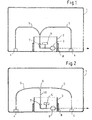
- FIG. 1 shows a sectional view of a liquid container 1 according to the invention, in particular for an aqueous urea solution.
- the liquid container 1 comprises a buffer store 2 arranged in the installed position at the bottom of the liquid container 1, a liquid conveying unit 3 arranged inside the intermediate store 2, and two first filter elements 4 arranged in the installed position on the bottom outside the intermediate store 2, each with a liquid line 5 with the liquid conveying unit 3 are connected.
- the first filter elements 4 are formed so that the filter fabric of the first filter elements 4 are permeable to the liquid in the liquid container 1 and impermeable to air.
- a second filter element 6 is arranged, which is formed so that the filter fabric of the second filter element 6 is permeable to the liquid in the liquid container and impermeable to air.
- the breakthrough pressure of the second filter element 6, in which air is conveyed through the filter element, is greater than the breakthrough pressure of the first filter elements 4.
- the liquid container 1 further comprises a first valve 7 between the liquid feed unit 3 and the first filter elements 4, wherein the opening pressure of the first Valve 7 is smaller than the breakthrough pressure of the second filter element. 6
- the opening pressure of the first valve 7 can be influenced by the breakdown pressure of the first filter elements 4, since these are connected in series in the flow direction. That the opening pressure of the first valve 7 is smaller than the breakthrough pressure of the second filter element 6 is to be understood that the series connection of the first filter element 4 and the first valve 7 has a total opening pressure, which is smaller than the breakthrough pressure of the second filter element.
- the second filter element 6 has a breakthrough pressure of 100 mbar
- the first filter elements 4 a breakthrough pressure of 50 mbar
- the first valve has an opening pressure of 25 mbar.
- a liquid container 1 designed in this way ensures that first the liquid is conveyed out of the buffer 2 by means of the liquid conveying unit 3. Subsequently, when the buffer 2 contains no liquid, opens before a breakthrough of the second filter element 6, the first valve 7 and the liquid is sucked through the first filter elements 4 and the liquid lines 5 from different points at the bottom of the liquid container 1 until it is completely emptied is.
- these at least two filter cloths of the second filter element 6 correspond to the filter cloth of the first filter element 4.
- the buffer 2 comprises a heating element 8 in order to heat the liquid in the buffer 2 or to melt it after freezing.
- the buffer 2 is designed as a swirl pot to restrict movement of the liquid during movement of the liquid container, for example when inserted into a motor vehicle, or to ensure that the second filter element is surrounded by liquid as long as possible.
- the second filter element 6 can be arranged on in the installation position bottom of the buffer to ensure the most complete possible emptying of the buffer.
- the first filter elements 4 are arranged in the installed position at the lowest points of the liquid container 1.
- the intuitionbrechdruck the first filter elements 4 is the same size in the illustrated embodiment, to make no selection between the two first filter elements 4.
- the in FIG. 1 shown liquid container can be prepared for example by blow molding or injection molding and is used to transport aqueous urea solution in a motor vehicle, wherein the aqueous urea solution is fed to an SCR catalyst.
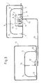
- the in FIG. 2 illustrated liquid container 1 for an aqueous urea solution comprises a arranged in the installed position at the bottom of the liquid container 1 buffer 2, a liquid conveying unit 3, at least two in installation position on the ground outside of the buffer 2 arranged first filter elements 4, each connected via a liquid line 5 to the liquid conveying unit 3 are, wherein the first filter elements 4 are formed so that the filter fabric of the first filter elements 4 is permeable to the liquid container 1 located liquid and impermeable to air.
- a second filter element 6 is arranged, which is formed so that the filter fabric of the second filter element 6 is permeable to the liquid in the liquid container and impermeable to air, wherein the breakthrough pressure of the second filter element 6, In which is conveyed through the filter element air, is greater than the breakthrough pressure of the first filter elements 4.
- a first valve 7 is arranged, wherein the opening pressure of the first valve 7 is smaller than the breakthrough pressure of the second filter element 6th
- the first filter elements 4 are each connected via a liquid line 5 to a collection point 9 and the collection point 9 is connected via a liquid collecting line 10 with the liquid conveying unit 3.
- the collecting point 10 is arranged in the installed position at the highest point in the liquid connection between the first filter elements 4 and the liquid conveying unit 3.
- FIG. 3 is a liquid container 1 according to FIG. 2 which further comprises a second liquid container 11 arranged outside the liquid container 1 with at least one third filter element 12 arranged in the installed position on the bottom, wherein the second liquid container 11 is connected to the liquid conveying unit 3 via the at least one third filter element 12 and a liquid connection line 13.
- the liquid container 1 is also referred to as an active container, since it comprises active components such as the liquid delivery unit 3 and the second liquid container 11 is referred to as a passive container, since this contains no active components.
- a two-part embodiment of the liquid container 1, 11 has several advantages. On the one hand, the containers can be made smaller and thus better adapted to the space available at the installation site. On the other hand, it is sufficient if one of the two containers comprises a heating device 8 in order to provide sufficient liquid even at low temperatures. The liquid in a smaller liquid container 1, 11 can be defrosted faster than in a large container.
- the liquid container 1 in conjunction with the second liquid container 11 from FIG. 3 further comprises a second valve 14 between the second filter element 6 and the liquid feed unit 3 and a third valve 15 between the third filter element 12 and the liquid feed unit 3, wherein the opening pressure of the second valve 14 is less than the opening pressure of the first valve 7 and the opening pressure of the third Valve 15 is smaller than the opening pressure of the second valve 14.
- FIG. 3 illustrated embodiment has over the prior art has the advantage that between the active container and passive container no additional liquid delivery unit is needed.
- the liquid container 11 comprises a fourth valve 19 between the liquid conveying unit 3 and the interior of the buffer 2, to allow a backflow of liquid from the liquid conveying unit 3 into the buffer 2, for example during a backwashing of the liquid line between Liquid delivery unit 3 and the consumer.
- the fourth valve 19 is designed as a one-way valve in the form of a check valve. This has the advantage that the liquid is backwashed into the intermediate storage means 2 heated by means of the heating element 8, whereby a renewed freezing of the liquid is prevented or slowed down.
- the fourth valve 19 may be formed integrally with the second valve 14. The line between the liquid delivery unit 3 and the consumer is backwashed after switching off the consumer to empty them from the liquid to prevent freezing of the liquid within the conduit to the consumer.
- the second liquid container 11 may also comprise a plurality of third filter elements 12 which are connected via liquid lines 5 to a second collection point 16 and wherein the second collection point 16 is connected via the liquid connection line 13 to the liquid delivery unit 3, as in FIG. 3 indicated by the dashed lines.
- FIG. 4 shows a non-inventive liquid container 1, in particular for an aqueous urea solution, comprising a liquid conveying unit 3, four arranged in the installed position at the bottom of the liquid container 1 filter elements 4, the first filter elements 4 are each connected via a liquid line 5 to a collection point 9 and the collection point. 9 is connected via a liquid collecting line 10 with the liquid conveying unit 3.
- the collecting point 9 is the highest point in the fluid connection between the first filter elements 4 and the liquid conveying unit 3 in the installation position.
- Such a configuration has the advantage that, as soon as the liquid conveying unit 3 delivers liquid through a first filter element 4 the associated liquid line 5 and the liquid collecting line 10 that liquid level in the other liquid lines 5 to the other first filter elements 4 does not decrease by a pressure drop, but remains consistently high.
- the other liquid lines 5 are the other first Filter elements 4 at least partially, preferably completely, filled with liquid and it can be supplied to the consumer without the promotion of larger amounts of air liquid.
- the liquid container 1 off FIG. 4 further comprising a second liquid container 11 arranged outside the liquid container 1 with at least one third filter element 12 arranged in the installed position on the bottom, wherein the second liquid container 11 is connected to the liquid conveying unit 3 via the at least one third filter element 12 and a liquid connection line 13.
- a first valve 7 is provided between the first filter elements 4 and the liquid conveying unit 3 and a third valve 15 between the third filter elements 12 and the liquid conveying unit 3, wherein the opening pressure of the third Valve 15 is smaller than the opening pressure of the first valve 7,
- a fourth valve 19 is arranged, so that the backwashed from the line between liquid conveying unit 3 and consumer liquid enters the heated buffer 2.
- the fourth valve 19 can also be arranged so that a backwashing of the liquid takes place via the second filter element 6.
- the buffer 2 and / or the second liquid container 11 the first filter elements 4, the second filter elements 6 and the third filter elements 12 are arranged at the bottom of each container.
- a liquid container 1 not according to the invention may comprise a filling nozzle 17 and / or a ventilation element 18, as in FIG FIG. 4 shown.
- first valves 7, second valves 14 and third valves 15 are all formed as a one-way valve, for example in the form of a check valve.
Landscapes
- Engineering & Computer Science (AREA)
- Chemical & Material Sciences (AREA)
- Chemical Kinetics & Catalysis (AREA)
- Combustion & Propulsion (AREA)
- Mechanical Engineering (AREA)
- General Engineering & Computer Science (AREA)
- Health & Medical Sciences (AREA)
- Toxicology (AREA)
- Exhaust Gas After Treatment (AREA)
Claims (13)
- Réservoir de liquide (1), en particulier pour une solution d'urée aqueuse, comprenant :- un accumulateur intermédiaire (2) agencé sur le fond du réservoir de liquide (1) dans la position de montage,- une unité de transport de liquide (3),- au moins un et de préférence plusieurs premiers éléments filtrants (4) agencés sur le fond à l'extérieur de l'accumulateur intermédiaire (2) dans la position de montage, qui sont chacun reliés à l'unité de transport de liquide (3) au moyen d'une conduite de liquide (5),dans lequel les premiers éléments filtrants (4) sont réalisés de telle sorte que le tissu filtrant des premiers éléments filtrants (4) est perméable pour le liquide se trouvant dans le réservoir de liquide (1) et étanche pour l'air,
dans lequel un deuxième élément filtrant (6) est agencé entre l'intérieur de l'accumulateur intermédiaire (2) et l'unité de transport de liquide (3), lequel est réalisé de telle sorte que le tissu filtrant du deuxième élément filtrant (6) est perméable pour le liquide se trouvant dans le réservoir de liquide (1) et étanche pour l'air,
comprenant en outre une première vanne (7) entre l'unité de transport de liquide (3) et les premiers éléments filtrants (4),
caractérisé en ce que la pression de perforation du deuxième élément filtrant (6), à laquelle l'air circule à travers l'élément filtrant, est supérieure à la pression de perforation des premiers éléments filtrants (4),
étant entendu que la pression d'ouverture de la première vanne (7) est inférieure à la pression de perforation du deuxième élément filtrant (6). - Réservoir de liquide (1) selon la revendication 1, dans lequel le deuxième élément filtrant (6) comprend au moins deux tissus filtrants agencés l'un derrière l'autre dans le sens du transport, ce par quoi la pression de perforation du deuxième élément filtrant (6) est augmentée.
- Réservoir de liquide (1) selon la revendication 2, dans lequel les au moins deux tissus filtrants du deuxième élément filtrant (6) correspondent au tissu filtrant du premier élément filtrant (4) en ce qui concerne la pression de perforation et/ou le matériau utilisé.
- Réservoir de liquide (1) selon l'une des revendications 1 à 3, dans lequel les premiers éléments filtrants (4) sont chacun reliés à un point de collecte (9) au moyen d'une conduite de liquide (5) et le point de collecte (9) est relié à l'unité de transport de liquide (3) au moyen d'une conduite de collecte de liquide (10).
- Réservoir de liquide (1) selon la revendication 4, dans lequel le point de collecte (9) est le point le plus élevé dans la position de montage dans le raccordement de liquide entre les premiers éléments filtrants (4) et l'unité de transport de liquide (3).
- Réservoir de liquide (1) selon la revendication 4 ou 5, dans lequel la première vanne (7) est agencée dans la conduite de collecte de liquide (10).
- Réservoir de liquide (1) selon l'une des revendications 1 à 6, dans lequel l'accumulateur intermédiaire (2) comprend un élément chauffant (8) afin de séparer par fusion ou de chauffer le liquide se trouvant dans l'accumulateur intermédiaire (2) et/ou il est réalisé en tant que pot de tourbillonnement.
- Réservoir de liquide (1) selon l'une des revendications 1 à 7, comprenant en outre un deuxième réservoir de liquide (11) agencé à l'extérieur du réservoir de liquide (1) ayant au moins un troisième élément filtrant (12) agencé sur le fond dans la position de montage, étant entendu que le deuxième réservoir de liquide (11) est relié à l'unité de transport de liquide (3) au moyen de l'au moins un troisième élément filtrant (12) et d'une conduite de raccordement de liquide (13).
- Réservoir de liquide (1) selon la revendication 8, comprenant en outre une deuxième vanne (14) entre le deuxième élément filtrant (6) et l'unité de transport de liquide (3) et une troisième vanne (15) entre le troisième élément filtrant (12) et l'unité de transport de liquide (3),
étant entendu que la pression d'ouverture de la deuxième vanne (14) est inférieure à la pression d'ouverture de la première vanne (7) et que la pression d'ouverture de la troisième vanne (15) est inférieure à la pression d'ouverture de la deuxième vanne (14). - Réservoir de liquide (1) selon la revendication 8 ou 9, comprenant en outre une quatrième vanne (19) entre l'unité de transport de liquide (3) et l'intérieur du réservoir de liquide (1), de préférence l'intérieur de l'accumulateur intermédiaire (2).
- Réservoir de liquide (1) selon l'une des revendications 8 à 10, comprenant en outre un deuxième point de collecte (16) dans le deuxième réservoir de liquide (11), étant entendu que le deuxième point de collecte (16) est de préférence le point le plus élevé dans la position de montage de la conduite de liquide (5) à l'intérieur du deuxième réservoir de liquide (11).
- Réservoir de liquide (1) selon l'une des revendications 8 à 11, dans lequel le deuxième réservoir de liquide (11) est agencé dans la position de montage au-dessus ou en dessous du premier réservoir de liquide (1), étant entendu que la conduite de raccordement de liquide (13) ne présente de préférence pas d'unité de transport de liquide (3).
- Réservoir de liquide (1) selon l'une des revendications 1 à 12, dans lequel le deuxième élément filtrant (6) est agencé dans la position de montage sur le fond de l'accumulateur intermédiaire (2).
Priority Applications (1)
| Application Number | Priority Date | Filing Date | Title |
|---|---|---|---|
| EP12007406.7A EP2554813B1 (fr) | 2010-11-12 | 2011-09-21 | Réservoir de liquide, en particulier pour une solution d'urée aqueuse |
Applications Claiming Priority (1)
| Application Number | Priority Date | Filing Date | Title |
|---|---|---|---|
| DE102010051072A DE102010051072B4 (de) | 2010-11-12 | 2010-11-12 | Flüssigkeitsbehälter, insbesondere für eine wässrige Harnstofflösung |
Related Child Applications (2)
| Application Number | Title | Priority Date | Filing Date |
|---|---|---|---|
| EP12007406.7A Division EP2554813B1 (fr) | 2010-11-12 | 2011-09-21 | Réservoir de liquide, en particulier pour une solution d'urée aqueuse |
| EP12007406.7 Division-Into | 2012-10-30 |
Publications (2)
| Publication Number | Publication Date |
|---|---|
| EP2453115A1 EP2453115A1 (fr) | 2012-05-16 |
| EP2453115B1 true EP2453115B1 (fr) | 2013-07-10 |
Family
ID=44650908
Family Applications (2)
| Application Number | Title | Priority Date | Filing Date |
|---|---|---|---|
| EP11007663.5A Not-in-force EP2453115B1 (fr) | 2010-11-12 | 2011-09-21 | Réservoir de liquide, en particulier pour une solution d'urée aqueuse |
| EP12007406.7A Not-in-force EP2554813B1 (fr) | 2010-11-12 | 2011-09-21 | Réservoir de liquide, en particulier pour une solution d'urée aqueuse |
Family Applications After (1)
| Application Number | Title | Priority Date | Filing Date |
|---|---|---|---|
| EP12007406.7A Not-in-force EP2554813B1 (fr) | 2010-11-12 | 2011-09-21 | Réservoir de liquide, en particulier pour une solution d'urée aqueuse |
Country Status (7)
| Country | Link |
|---|---|
| US (1) | US9803530B2 (fr) |
| EP (2) | EP2453115B1 (fr) |
| JP (1) | JP5746360B2 (fr) |
| KR (1) | KR101503193B1 (fr) |
| CN (2) | CN103189608B (fr) |
| DE (1) | DE102010051072B4 (fr) |
| WO (1) | WO2012062400A1 (fr) |
Families Citing this family (21)
| Publication number | Priority date | Publication date | Assignee | Title |
|---|---|---|---|---|
| FR2941156A1 (fr) * | 2009-01-19 | 2010-07-23 | Cummins Filtration | Dispositif de filtration pour liquide circulant dans un moteur ou un equipement hydraulique, comprenant des moyens de chauffage du liquide jouxtant les moyens de filtration |
| DE102010051072B4 (de) * | 2010-11-12 | 2012-11-08 | Kautex Textron Gmbh & Co. Kg | Flüssigkeitsbehälter, insbesondere für eine wässrige Harnstofflösung |
| DE102011105893B4 (de) * | 2011-06-27 | 2014-03-06 | Kautex Textron Gmbh & Co. Kg | Harnstoffbehälter für ein Kfz |
| DE102012017288A1 (de) * | 2012-08-31 | 2014-03-06 | Hydac Filtertechnik Gmbh | Einrichtung zur Saugfiltration von Fluiden |
| DE102012020039B4 (de) * | 2012-10-12 | 2015-02-19 | Kautex Textron Gmbh & Co. Kg | Einrichtung zur Bevorratung und Förderung eines Additivs zur katalytischen Abgasentstickung an einem Kfz |
| DE102012020948B4 (de) * | 2012-10-25 | 2017-02-16 | Kautex Textron Gmbh & Co. Kg | Einrichtung zur Bevorratung und Förderung eines flüssigen Additivs, insbesondere zur katalytischen Abgasentstickung an einem Kfz |
| EP2738032B1 (fr) * | 2012-11-30 | 2016-02-03 | Magna Steyr Fuel Systems GesmbH | Système de réservoir pour un véhicule automobile |
| DE102013001237B4 (de) | 2013-01-25 | 2015-04-16 | Kautex Textron Gmbh & Co. Kg | Filtervorrichtung für einen Flüssigkeitsbehälter, insbesondere für wässrige Harnstofflösung |
| US9089791B2 (en) * | 2013-03-14 | 2015-07-28 | Cummins Ip, Inc. | Apparatus, method, and system for reductant filtration |
| JP2014202088A (ja) * | 2013-04-02 | 2014-10-27 | ヤマハ発動機株式会社 | 燃料供給装置及び鞍乗型車両 |
| EP2846011A1 (fr) * | 2013-09-04 | 2015-03-11 | Inergy Automotive Systems Research (Société Anonyme) | Procédé et système pour purifier les gaz d'échappement d'un moteur à combustion |
| EP2857645B2 (fr) | 2013-10-02 | 2019-01-09 | Magna Steyr Fuel Systems GmbH | Récipient pour solution d'urée et procédé de fabrication d'un tel récipient |
| US10328366B2 (en) * | 2015-05-21 | 2019-06-25 | Caterpillar Inc. | Fluid reservoir having inlet filtering |
| DE102016220625A1 (de) | 2016-10-20 | 2018-04-26 | Bayerische Motoren Werke Aktiengesellschaft | Behälter für ein flüssiges Betriebsmittel eines Kraftfahrzeugs |
| EP3324030A1 (fr) | 2016-11-17 | 2018-05-23 | Plastic Omnium Advanced Innovation and Research | Système de stockage d'une solution aqueuse à bord d'un véhicule |
| EP3324031A1 (fr) * | 2016-11-17 | 2018-05-23 | Plastic Omnium Advanced Innovation and Research | Système de stockage d'une solution aqueuse à bord d'un véhicule |
| DE102017115820A1 (de) * | 2017-07-13 | 2019-01-17 | Kautex Textron Gmbh & Co. Kg | Flüssigkeitsbehälter für ein Kraftfahrzeug |
| CN107965669A (zh) * | 2017-12-15 | 2018-04-27 | 四川北方硝化棉股份有限公司 | 液体输送装置和硝化棉生产废水输送系统 |
| CN108301906B (zh) * | 2018-03-21 | 2023-11-03 | 武汉洛特福动力技术有限公司 | 空气加压渗水清洗装置 |
| DE102018208643A1 (de) * | 2018-05-30 | 2019-12-05 | Röchling Automotive SE & Co. KG | Kfz-Tankbaugruppe und Entnahmemodul mit einem porösen Förderkörper |
| FR3093676B1 (fr) * | 2019-03-14 | 2021-04-02 | Continental Automotive Gmbh | Dispositif de stockage de liquide pour véhicule automobile |
Family Cites Families (24)
| Publication number | Priority date | Publication date | Assignee | Title |
|---|---|---|---|---|
| JPS60169727A (ja) | 1984-02-13 | 1985-09-03 | Agency Of Ind Science & Technol | 簡易放射率計 |
| US4546750A (en) * | 1984-07-12 | 1985-10-15 | General Motors Corporation | Secondary reservoir for a fuel tank |
| JPS6278523A (ja) | 1985-10-02 | 1987-04-10 | Canon Inc | 望遠型ズ−ムレンズ |
| JPS6283224A (ja) | 1985-10-08 | 1987-04-16 | Mitsubishi Electric Corp | 燃料供給装置 |
| JPS6278523U (fr) * | 1985-11-06 | 1987-05-20 | ||
| JPS6284990U (fr) | 1985-11-15 | 1987-05-30 | ||
| JPH0778116B2 (ja) | 1987-02-09 | 1995-08-23 | 住友化学工業株式会社 | ポリピロ−ル類水分散液の製造方法 |
| JPS63193926U (fr) * | 1987-05-30 | 1988-12-14 | ||
| JPS63306271A (ja) | 1987-06-09 | 1988-12-14 | Mitsuba Electric Mfg Co Ltd | 燃料供給装置 |
| FR2746855B1 (fr) * | 1996-03-28 | 1998-06-19 | Marwal Systems | Dispositif de pompage de carburant pour reservoir multipoches |
| DE19619992A1 (de) * | 1996-05-17 | 1997-11-20 | Bosch Gmbh Robert | Kraftstoff-Fördermodul mit integriertem Kraftstoff-Feinfilter |
| DE19644464B4 (de) * | 1996-10-25 | 2007-06-14 | Bayerische Motoren Werke Ag | Kraftstoffbehälter für ein Kraftfahrzeug |
| US5951050A (en) | 1997-09-18 | 1999-09-14 | Siekmann; Jim | Integral reservoir for tank |
| DE10340246B3 (de) | 2003-08-29 | 2005-03-10 | Siemens Ag | Kraftstoffbehälter für ein Kraftfahrzeug und Kraftstoff-Fördereinheit |
| DE102005037201A1 (de) * | 2005-08-06 | 2007-02-22 | Eichenauer Heizelemente Gmbh & Co. Kg | Heizsystem |
| DE102007050272A1 (de) * | 2007-10-18 | 2009-04-23 | Robert Bosch Gmbh | Tank zur Bevorratung eines Reduktionsmittels |
| US20110209789A1 (en) | 2008-11-07 | 2011-09-01 | Honda Motor Co., Ltd. | Fuel tank |
| DE102009010406B4 (de) | 2009-02-26 | 2011-09-22 | Magna Steyr Fuel Systems Gesmbh | Einfüllkopf für einen Kraftstoffbehälter mit einer Schutzvorrichtung |
| DE102009011518A1 (de) * | 2009-03-06 | 2010-09-16 | Kautex Textron Gmbh & Co. Kg | Reduktionsmittelbehälter |
| JP5249108B2 (ja) | 2009-03-31 | 2013-07-31 | 三菱電機株式会社 | 燃料供給装置 |
| JP2010248944A (ja) | 2009-04-13 | 2010-11-04 | Toyota Motor Corp | 尿素タンク構造 |
| WO2010119116A2 (fr) * | 2009-04-16 | 2010-10-21 | Inergy Automotive Systems Research (Société Anonyme) | Système et procédé de stockage d'un additif et d'injection de celui-ci dans les gaz d'échappement d'un moteur |
| JP2011026980A (ja) | 2009-07-22 | 2011-02-10 | Aisan Industry Co Ltd | 燃料供給装置 |
| DE102010051072B4 (de) * | 2010-11-12 | 2012-11-08 | Kautex Textron Gmbh & Co. Kg | Flüssigkeitsbehälter, insbesondere für eine wässrige Harnstofflösung |
-
2010
- 2010-11-12 DE DE102010051072A patent/DE102010051072B4/de not_active Expired - Fee Related
-
2011
- 2011-09-21 EP EP11007663.5A patent/EP2453115B1/fr not_active Not-in-force
- 2011-09-21 EP EP12007406.7A patent/EP2554813B1/fr not_active Not-in-force
- 2011-10-18 US US13/885,086 patent/US9803530B2/en active Active
- 2011-10-18 CN CN201180051219.9A patent/CN103189608B/zh not_active Expired - Fee Related
- 2011-10-18 CN CN201510105199.9A patent/CN104791054B/zh not_active Expired - Fee Related
- 2011-10-18 KR KR1020137012064A patent/KR101503193B1/ko active IP Right Grant
- 2011-10-18 JP JP2013538086A patent/JP5746360B2/ja not_active Expired - Fee Related
- 2011-10-18 WO PCT/EP2011/005213 patent/WO2012062400A1/fr active Application Filing
Also Published As
| Publication number | Publication date |
|---|---|
| US9803530B2 (en) | 2017-10-31 |
| CN104791054A (zh) | 2015-07-22 |
| US20130233850A1 (en) | 2013-09-12 |
| CN103189608B (zh) | 2015-06-17 |
| EP2554813B1 (fr) | 2014-07-09 |
| EP2453115A1 (fr) | 2012-05-16 |
| CN103189608A (zh) | 2013-07-03 |
| EP2554813A1 (fr) | 2013-02-06 |
| JP2013542371A (ja) | 2013-11-21 |
| DE102010051072A1 (de) | 2012-05-16 |
| DE102010051072B4 (de) | 2012-11-08 |
| KR20130067309A (ko) | 2013-06-21 |
| CN104791054B (zh) | 2018-01-05 |
| KR101503193B1 (ko) | 2015-03-24 |
| JP5746360B2 (ja) | 2015-07-08 |
| WO2012062400A1 (fr) | 2012-05-18 |
Similar Documents
| Publication | Publication Date | Title |
|---|---|---|
| EP2453115B1 (fr) | Réservoir de liquide, en particulier pour une solution d'urée aqueuse | |
| DE102009037564B4 (de) | Vorrichtung und Verfahren zur Dosierung eines Reduktionsmittels in einen Abgastrakt einer Brennkraftmaschine | |
| WO2008040589A1 (fr) | Réservoir d'alimentation pour un agent de réduction | |
| EP2094953A1 (fr) | Dispositif de dosage d'agent de réduction liquide | |
| EP2791481B1 (fr) | Système de dosage pour un produit liquide de retraitement des gaz d'échappement et procédé de dosage | |
| EP2707579B1 (fr) | Réservoir de stockage et unité fonctionnelle pour ledit réservoir | |
| EP2504540A1 (fr) | Procédé permettant de faire fonctionner un dispositif de transport d'un agent de réduction | |
| DE102006012855A1 (de) | Verfahren und Dosiersystem zur Schadstoffreduktion in Kraftfahrzeugabgasen | |
| EP1925354A1 (fr) | Dispositif de réduction catalytique | |
| DE102006061734A1 (de) | Vorrichtung zum Dosieren eines Reduktionsmittels | |
| DE102009011018A1 (de) | Vorrichtung zum Zuführen eines Hilfsmittels zu einer Abgasnachbehandlungseinrichtung eines Kraftfahrzeugs | |
| DE102016206637A1 (de) | Behälteranordnung für ein Kraftfahrzeug | |
| EP2288795B1 (fr) | Systeme scr dote de plusieurs reservoirs | |
| DE102012013468A1 (de) | Reduktionsmitteldosiersystem mit Entleerung der Reduktionsmittelleitung nach Beendigung der Dosierung | |
| DE102006048721B4 (de) | Katalytische Reduktionseinrichtung für eine katalytische Reduktion von Stickoxiden in Abgasanlagen | |
| DE102008042954A1 (de) | Dosiersystem für ein flüssiges Medium, insbesondere Harnstoff-Wasser-Lösung | |
| DE102016220625A1 (de) | Behälter für ein flüssiges Betriebsmittel eines Kraftfahrzeugs | |
| DE102013010872A1 (de) | Schwalltopf und Reservoir | |
| DE102009045721A1 (de) | Tank für ein flüssiges Reduktionsmittel | |
| WO2018137914A1 (fr) | Module de refoulement pour un système de dosage destiné à injecter un agent de réduction dans la ligne d'échappement d'un véhicule à moteur et système de dosage | |
| DE102011118626A1 (de) | Verfahren zum Betriebsstopp einer Dosiervorrichtung | |
| DE102010039103A1 (de) | Dosiersystem sowie 3/2-Wegeventil für ein Dosiersystem | |
| DE102010029334A1 (de) | Fluidspeichereinrichtung | |
| DE102018119406A1 (de) | Reduktionsmittelzusetzsystem | |
| EP4321740A2 (fr) | Système de filtration de fluides par aspiration |
Legal Events
| Date | Code | Title | Description |
|---|---|---|---|
| PUAI | Public reference made under article 153(3) epc to a published international application that has entered the european phase |
Free format text: ORIGINAL CODE: 0009012 |
|
| AK | Designated contracting states |
Kind code of ref document: A1 Designated state(s): AL AT BE BG CH CY CZ DE DK EE ES FI FR GB GR HR HU IE IS IT LI LT LU LV MC MK MT NL NO PL PT RO RS SE SI SK SM TR |
|
| AX | Request for extension of the european patent |
Extension state: BA ME |
|
| 17P | Request for examination filed |
Effective date: 20121030 |
|
| GRAP | Despatch of communication of intention to grant a patent |
Free format text: ORIGINAL CODE: EPIDOSNIGR1 |
|
| GRAS | Grant fee paid |
Free format text: ORIGINAL CODE: EPIDOSNIGR3 |
|
| GRAA | (expected) grant |
Free format text: ORIGINAL CODE: 0009210 |
|
| AK | Designated contracting states |
Kind code of ref document: B1 Designated state(s): AL AT BE BG CH CY CZ DE DK EE ES FI FR GB GR HR HU IE IS IT LI LT LU LV MC MK MT NL NO PL PT RO RS SE SI SK SM TR |
|
| REG | Reference to a national code |
Ref country code: GB Ref legal event code: FG4D Free format text: NOT ENGLISH |
|
| REG | Reference to a national code |
Ref country code: CH Ref legal event code: EP Ref country code: AT Ref legal event code: REF Ref document number: 621103 Country of ref document: AT Kind code of ref document: T Effective date: 20130715 |
|
| REG | Reference to a national code |
Ref country code: IE Ref legal event code: FG4D Free format text: LANGUAGE OF EP DOCUMENT: GERMAN |
|
| REG | Reference to a national code |
Ref country code: DE Ref legal event code: R096 Ref document number: 502011000997 Country of ref document: DE Effective date: 20130905 |
|
| PG25 | Lapsed in a contracting state [announced via postgrant information from national office to epo] |
Ref country code: SI Free format text: LAPSE BECAUSE OF FAILURE TO SUBMIT A TRANSLATION OF THE DESCRIPTION OR TO PAY THE FEE WITHIN THE PRESCRIBED TIME-LIMIT Effective date: 20130710 |
|
| REG | Reference to a national code |
Ref country code: NL Ref legal event code: VDEP Effective date: 20130710 |
|
| REG | Reference to a national code |
Ref country code: LT Ref legal event code: MG4D |
|
| PG25 | Lapsed in a contracting state [announced via postgrant information from national office to epo] |
Ref country code: HR Free format text: LAPSE BECAUSE OF FAILURE TO SUBMIT A TRANSLATION OF THE DESCRIPTION OR TO PAY THE FEE WITHIN THE PRESCRIBED TIME-LIMIT Effective date: 20130710 Ref country code: PT Free format text: LAPSE BECAUSE OF FAILURE TO SUBMIT A TRANSLATION OF THE DESCRIPTION OR TO PAY THE FEE WITHIN THE PRESCRIBED TIME-LIMIT Effective date: 20131111 Ref country code: SE Free format text: LAPSE BECAUSE OF FAILURE TO SUBMIT A TRANSLATION OF THE DESCRIPTION OR TO PAY THE FEE WITHIN THE PRESCRIBED TIME-LIMIT Effective date: 20130710 Ref country code: IS Free format text: LAPSE BECAUSE OF FAILURE TO SUBMIT A TRANSLATION OF THE DESCRIPTION OR TO PAY THE FEE WITHIN THE PRESCRIBED TIME-LIMIT Effective date: 20131110 Ref country code: LT Free format text: LAPSE BECAUSE OF FAILURE TO SUBMIT A TRANSLATION OF THE DESCRIPTION OR TO PAY THE FEE WITHIN THE PRESCRIBED TIME-LIMIT Effective date: 20130710 Ref country code: CY Free format text: LAPSE BECAUSE OF FAILURE TO SUBMIT A TRANSLATION OF THE DESCRIPTION OR TO PAY THE FEE WITHIN THE PRESCRIBED TIME-LIMIT Effective date: 20130821 Ref country code: NO Free format text: LAPSE BECAUSE OF FAILURE TO SUBMIT A TRANSLATION OF THE DESCRIPTION OR TO PAY THE FEE WITHIN THE PRESCRIBED TIME-LIMIT Effective date: 20131010 |
|
| PG25 | Lapsed in a contracting state [announced via postgrant information from national office to epo] |
Ref country code: NL Free format text: LAPSE BECAUSE OF FAILURE TO SUBMIT A TRANSLATION OF THE DESCRIPTION OR TO PAY THE FEE WITHIN THE PRESCRIBED TIME-LIMIT Effective date: 20130710 Ref country code: GR Free format text: LAPSE BECAUSE OF FAILURE TO SUBMIT A TRANSLATION OF THE DESCRIPTION OR TO PAY THE FEE WITHIN THE PRESCRIBED TIME-LIMIT Effective date: 20131011 Ref country code: PL Free format text: LAPSE BECAUSE OF FAILURE TO SUBMIT A TRANSLATION OF THE DESCRIPTION OR TO PAY THE FEE WITHIN THE PRESCRIBED TIME-LIMIT Effective date: 20130710 Ref country code: FI Free format text: LAPSE BECAUSE OF FAILURE TO SUBMIT A TRANSLATION OF THE DESCRIPTION OR TO PAY THE FEE WITHIN THE PRESCRIBED TIME-LIMIT Effective date: 20130710 Ref country code: LV Free format text: LAPSE BECAUSE OF FAILURE TO SUBMIT A TRANSLATION OF THE DESCRIPTION OR TO PAY THE FEE WITHIN THE PRESCRIBED TIME-LIMIT Effective date: 20130710 Ref country code: ES Free format text: LAPSE BECAUSE OF FAILURE TO SUBMIT A TRANSLATION OF THE DESCRIPTION OR TO PAY THE FEE WITHIN THE PRESCRIBED TIME-LIMIT Effective date: 20131021 |
|
| BERE | Be: lapsed |
Owner name: KAUTEX TEXTRON G.M.B.H. & CO. KG Effective date: 20130930 |
|
| PG25 | Lapsed in a contracting state [announced via postgrant information from national office to epo] |
Ref country code: CY Free format text: LAPSE BECAUSE OF FAILURE TO SUBMIT A TRANSLATION OF THE DESCRIPTION OR TO PAY THE FEE WITHIN THE PRESCRIBED TIME-LIMIT Effective date: 20130710 |
|
| REG | Reference to a national code |
Ref country code: DE Ref legal event code: R097 Ref document number: 502011000997 Country of ref document: DE |
|
| PG25 | Lapsed in a contracting state [announced via postgrant information from national office to epo] |
Ref country code: SK Free format text: LAPSE BECAUSE OF FAILURE TO SUBMIT A TRANSLATION OF THE DESCRIPTION OR TO PAY THE FEE WITHIN THE PRESCRIBED TIME-LIMIT Effective date: 20130710 Ref country code: EE Free format text: LAPSE BECAUSE OF FAILURE TO SUBMIT A TRANSLATION OF THE DESCRIPTION OR TO PAY THE FEE WITHIN THE PRESCRIBED TIME-LIMIT Effective date: 20130710 Ref country code: MC Free format text: LAPSE BECAUSE OF FAILURE TO SUBMIT A TRANSLATION OF THE DESCRIPTION OR TO PAY THE FEE WITHIN THE PRESCRIBED TIME-LIMIT Effective date: 20130710 Ref country code: DK Free format text: LAPSE BECAUSE OF FAILURE TO SUBMIT A TRANSLATION OF THE DESCRIPTION OR TO PAY THE FEE WITHIN THE PRESCRIBED TIME-LIMIT Effective date: 20130710 Ref country code: RO Free format text: LAPSE BECAUSE OF FAILURE TO SUBMIT A TRANSLATION OF THE DESCRIPTION OR TO PAY THE FEE WITHIN THE PRESCRIBED TIME-LIMIT Effective date: 20130710 |
|
| PLBE | No opposition filed within time limit |
Free format text: ORIGINAL CODE: 0009261 |
|
| STAA | Information on the status of an ep patent application or granted ep patent |
Free format text: STATUS: NO OPPOSITION FILED WITHIN TIME LIMIT |
|
| PG25 | Lapsed in a contracting state [announced via postgrant information from national office to epo] |
Ref country code: IT Free format text: LAPSE BECAUSE OF FAILURE TO SUBMIT A TRANSLATION OF THE DESCRIPTION OR TO PAY THE FEE WITHIN THE PRESCRIBED TIME-LIMIT Effective date: 20130710 |
|
| 26N | No opposition filed |
Effective date: 20140411 |
|
| REG | Reference to a national code |
Ref country code: DE Ref legal event code: R082 Ref document number: 502011000997 Country of ref document: DE Representative=s name: KIERDORF RITSCHEL RICHLY PATENTANWAELTE PARTG , DE Ref country code: DE Ref legal event code: R082 Ref document number: 502011000997 Country of ref document: DE Representative=s name: KIERDORF RITSCHEL PATENTANWAELTE PARTG MBB, DE Ref country code: DE Ref legal event code: R082 Ref document number: 502011000997 Country of ref document: DE Representative=s name: RICHLY & RITSCHEL PATENTANWAELTE PARTG MBB, DE |
|
| REG | Reference to a national code |
Ref country code: IE Ref legal event code: MM4A |
|
| REG | Reference to a national code |
Ref country code: DE Ref legal event code: R097 Ref document number: 502011000997 Country of ref document: DE Effective date: 20140411 |
|
| PG25 | Lapsed in a contracting state [announced via postgrant information from national office to epo] |
Ref country code: BE Free format text: LAPSE BECAUSE OF NON-PAYMENT OF DUE FEES Effective date: 20130930 Ref country code: IE Free format text: LAPSE BECAUSE OF NON-PAYMENT OF DUE FEES Effective date: 20130921 |
|
| REG | Reference to a national code |
Ref country code: CH Ref legal event code: PL |
|
| PG25 | Lapsed in a contracting state [announced via postgrant information from national office to epo] |
Ref country code: SM Free format text: LAPSE BECAUSE OF FAILURE TO SUBMIT A TRANSLATION OF THE DESCRIPTION OR TO PAY THE FEE WITHIN THE PRESCRIBED TIME-LIMIT Effective date: 20130710 |
|
| PG25 | Lapsed in a contracting state [announced via postgrant information from national office to epo] |
Ref country code: TR Free format text: LAPSE BECAUSE OF FAILURE TO SUBMIT A TRANSLATION OF THE DESCRIPTION OR TO PAY THE FEE WITHIN THE PRESCRIBED TIME-LIMIT Effective date: 20130710 Ref country code: MT Free format text: LAPSE BECAUSE OF FAILURE TO SUBMIT A TRANSLATION OF THE DESCRIPTION OR TO PAY THE FEE WITHIN THE PRESCRIBED TIME-LIMIT Effective date: 20130710 |
|
| PG25 | Lapsed in a contracting state [announced via postgrant information from national office to epo] |
Ref country code: BG Free format text: LAPSE BECAUSE OF FAILURE TO SUBMIT A TRANSLATION OF THE DESCRIPTION OR TO PAY THE FEE WITHIN THE PRESCRIBED TIME-LIMIT Effective date: 20130710 Ref country code: LU Free format text: LAPSE BECAUSE OF NON-PAYMENT OF DUE FEES Effective date: 20130921 Ref country code: MK Free format text: LAPSE BECAUSE OF FAILURE TO SUBMIT A TRANSLATION OF THE DESCRIPTION OR TO PAY THE FEE WITHIN THE PRESCRIBED TIME-LIMIT Effective date: 20130710 Ref country code: CH Free format text: LAPSE BECAUSE OF NON-PAYMENT OF DUE FEES Effective date: 20140930 Ref country code: HU Free format text: LAPSE BECAUSE OF FAILURE TO SUBMIT A TRANSLATION OF THE DESCRIPTION OR TO PAY THE FEE WITHIN THE PRESCRIBED TIME-LIMIT; INVALID AB INITIO Effective date: 20110921 Ref country code: LI Free format text: LAPSE BECAUSE OF NON-PAYMENT OF DUE FEES Effective date: 20140930 Ref country code: RS Free format text: LAPSE BECAUSE OF FAILURE TO SUBMIT A TRANSLATION OF THE DESCRIPTION OR TO PAY THE FEE WITHIN THE PRESCRIBED TIME-LIMIT Effective date: 20131010 |
|
| REG | Reference to a national code |
Ref country code: FR Ref legal event code: PLFP Year of fee payment: 5 |
|
| GBPC | Gb: european patent ceased through non-payment of renewal fee |
Effective date: 20150921 |
|
| PG25 | Lapsed in a contracting state [announced via postgrant information from national office to epo] |
Ref country code: GB Free format text: LAPSE BECAUSE OF NON-PAYMENT OF DUE FEES Effective date: 20150921 |
|
| REG | Reference to a national code |
Ref country code: FR Ref legal event code: PLFP Year of fee payment: 6 |
|
| REG | Reference to a national code |
Ref country code: FR Ref legal event code: PLFP Year of fee payment: 7 |
|
| REG | Reference to a national code |
Ref country code: AT Ref legal event code: MM01 Ref document number: 621103 Country of ref document: AT Kind code of ref document: T Effective date: 20160921 |
|
| PG25 | Lapsed in a contracting state [announced via postgrant information from national office to epo] |
Ref country code: AT Free format text: LAPSE BECAUSE OF NON-PAYMENT OF DUE FEES Effective date: 20160921 |
|
| REG | Reference to a national code |
Ref country code: FR Ref legal event code: PLFP Year of fee payment: 8 |
|
| PG25 | Lapsed in a contracting state [announced via postgrant information from national office to epo] |
Ref country code: AL Free format text: LAPSE BECAUSE OF FAILURE TO SUBMIT A TRANSLATION OF THE DESCRIPTION OR TO PAY THE FEE WITHIN THE PRESCRIBED TIME-LIMIT Effective date: 20130710 |
|
| PGFP | Annual fee paid to national office [announced via postgrant information from national office to epo] |
Ref country code: CZ Payment date: 20200918 Year of fee payment: 10 Ref country code: FR Payment date: 20200914 Year of fee payment: 10 Ref country code: DE Payment date: 20200831 Year of fee payment: 10 |
|
| REG | Reference to a national code |
Ref country code: DE Ref legal event code: R119 Ref document number: 502011000997 Country of ref document: DE |
|
| PG25 | Lapsed in a contracting state [announced via postgrant information from national office to epo] |
Ref country code: CZ Free format text: LAPSE BECAUSE OF NON-PAYMENT OF DUE FEES Effective date: 20210921 |
|
| PG25 | Lapsed in a contracting state [announced via postgrant information from national office to epo] |
Ref country code: FR Free format text: LAPSE BECAUSE OF NON-PAYMENT OF DUE FEES Effective date: 20210930 Ref country code: DE Free format text: LAPSE BECAUSE OF NON-PAYMENT OF DUE FEES Effective date: 20220401 |