EP2707579B1 - Réservoir de stockage et unité fonctionnelle pour ledit réservoir - Google Patents
Réservoir de stockage et unité fonctionnelle pour ledit réservoir Download PDFInfo
- Publication number
- EP2707579B1 EP2707579B1 EP12711852.9A EP12711852A EP2707579B1 EP 2707579 B1 EP2707579 B1 EP 2707579B1 EP 12711852 A EP12711852 A EP 12711852A EP 2707579 B1 EP2707579 B1 EP 2707579B1
- Authority
- EP
- European Patent Office
- Prior art keywords
- functional unit
- storage tank
- reducing agent
- heat conducting
- reservoir
- Prior art date
- Legal status (The legal status is an assumption and is not a legal conclusion. Google has not performed a legal analysis and makes no representation as to the accuracy of the status listed.)
- Not-in-force
Links
Images

Classifications
-
- F—MECHANICAL ENGINEERING; LIGHTING; HEATING; WEAPONS; BLASTING
- F01—MACHINES OR ENGINES IN GENERAL; ENGINE PLANTS IN GENERAL; STEAM ENGINES
- F01N—GAS-FLOW SILENCERS OR EXHAUST APPARATUS FOR MACHINES OR ENGINES IN GENERAL; GAS-FLOW SILENCERS OR EXHAUST APPARATUS FOR INTERNAL COMBUSTION ENGINES
- F01N3/00—Exhaust or silencing apparatus having means for purifying, rendering innocuous, or otherwise treating exhaust
- F01N3/08—Exhaust or silencing apparatus having means for purifying, rendering innocuous, or otherwise treating exhaust for rendering innocuous
- F01N3/10—Exhaust or silencing apparatus having means for purifying, rendering innocuous, or otherwise treating exhaust for rendering innocuous by thermal or catalytic conversion of noxious components of exhaust
- F01N3/18—Exhaust or silencing apparatus having means for purifying, rendering innocuous, or otherwise treating exhaust for rendering innocuous by thermal or catalytic conversion of noxious components of exhaust characterised by methods of operation; Control
- F01N3/20—Exhaust or silencing apparatus having means for purifying, rendering innocuous, or otherwise treating exhaust for rendering innocuous by thermal or catalytic conversion of noxious components of exhaust characterised by methods of operation; Control specially adapted for catalytic conversion ; Methods of operation or control of catalytic converters
- F01N3/2066—Selective catalytic reduction [SCR]
-
- F—MECHANICAL ENGINEERING; LIGHTING; HEATING; WEAPONS; BLASTING
- F01—MACHINES OR ENGINES IN GENERAL; ENGINE PLANTS IN GENERAL; STEAM ENGINES
- F01N—GAS-FLOW SILENCERS OR EXHAUST APPARATUS FOR MACHINES OR ENGINES IN GENERAL; GAS-FLOW SILENCERS OR EXHAUST APPARATUS FOR INTERNAL COMBUSTION ENGINES
- F01N2610/00—Adding substances to exhaust gases
- F01N2610/02—Adding substances to exhaust gases the substance being ammonia or urea
-
- F—MECHANICAL ENGINEERING; LIGHTING; HEATING; WEAPONS; BLASTING
- F01—MACHINES OR ENGINES IN GENERAL; ENGINE PLANTS IN GENERAL; STEAM ENGINES
- F01N—GAS-FLOW SILENCERS OR EXHAUST APPARATUS FOR MACHINES OR ENGINES IN GENERAL; GAS-FLOW SILENCERS OR EXHAUST APPARATUS FOR INTERNAL COMBUSTION ENGINES
- F01N2610/00—Adding substances to exhaust gases
- F01N2610/10—Adding substances to exhaust gases the substance being heated, e.g. by heating tank or supply line of the added substance
-
- F—MECHANICAL ENGINEERING; LIGHTING; HEATING; WEAPONS; BLASTING
- F01—MACHINES OR ENGINES IN GENERAL; ENGINE PLANTS IN GENERAL; STEAM ENGINES
- F01N—GAS-FLOW SILENCERS OR EXHAUST APPARATUS FOR MACHINES OR ENGINES IN GENERAL; GAS-FLOW SILENCERS OR EXHAUST APPARATUS FOR INTERNAL COMBUSTION ENGINES
- F01N2610/00—Adding substances to exhaust gases
- F01N2610/14—Arrangements for the supply of substances, e.g. conduits
- F01N2610/1406—Storage means for substances, e.g. tanks or reservoirs
-
- F—MECHANICAL ENGINEERING; LIGHTING; HEATING; WEAPONS; BLASTING
- F01—MACHINES OR ENGINES IN GENERAL; ENGINE PLANTS IN GENERAL; STEAM ENGINES
- F01N—GAS-FLOW SILENCERS OR EXHAUST APPARATUS FOR MACHINES OR ENGINES IN GENERAL; GAS-FLOW SILENCERS OR EXHAUST APPARATUS FOR INTERNAL COMBUSTION ENGINES
- F01N2610/00—Adding substances to exhaust gases
- F01N2610/14—Arrangements for the supply of substances, e.g. conduits
- F01N2610/1433—Pumps
-
- F—MECHANICAL ENGINEERING; LIGHTING; HEATING; WEAPONS; BLASTING
- F01—MACHINES OR ENGINES IN GENERAL; ENGINE PLANTS IN GENERAL; STEAM ENGINES
- F01N—GAS-FLOW SILENCERS OR EXHAUST APPARATUS FOR MACHINES OR ENGINES IN GENERAL; GAS-FLOW SILENCERS OR EXHAUST APPARATUS FOR INTERNAL COMBUSTION ENGINES
- F01N2610/00—Adding substances to exhaust gases
- F01N2610/14—Arrangements for the supply of substances, e.g. conduits
- F01N2610/1466—Means for venting air out of conduits or tanks
-
- Y—GENERAL TAGGING OF NEW TECHNOLOGICAL DEVELOPMENTS; GENERAL TAGGING OF CROSS-SECTIONAL TECHNOLOGIES SPANNING OVER SEVERAL SECTIONS OF THE IPC; TECHNICAL SUBJECTS COVERED BY FORMER USPC CROSS-REFERENCE ART COLLECTIONS [XRACs] AND DIGESTS
- Y02—TECHNOLOGIES OR APPLICATIONS FOR MITIGATION OR ADAPTATION AGAINST CLIMATE CHANGE
- Y02A—TECHNOLOGIES FOR ADAPTATION TO CLIMATE CHANGE
- Y02A50/00—TECHNOLOGIES FOR ADAPTATION TO CLIMATE CHANGE in human health protection, e.g. against extreme weather
- Y02A50/20—Air quality improvement or preservation, e.g. vehicle emission control or emission reduction by using catalytic converters
-
- Y—GENERAL TAGGING OF NEW TECHNOLOGICAL DEVELOPMENTS; GENERAL TAGGING OF CROSS-SECTIONAL TECHNOLOGIES SPANNING OVER SEVERAL SECTIONS OF THE IPC; TECHNICAL SUBJECTS COVERED BY FORMER USPC CROSS-REFERENCE ART COLLECTIONS [XRACs] AND DIGESTS
- Y02—TECHNOLOGIES OR APPLICATIONS FOR MITIGATION OR ADAPTATION AGAINST CLIMATE CHANGE
- Y02T—CLIMATE CHANGE MITIGATION TECHNOLOGIES RELATED TO TRANSPORTATION
- Y02T10/00—Road transport of goods or passengers
- Y02T10/10—Internal combustion engine [ICE] based vehicles
- Y02T10/12—Improving ICE efficiencies
Definitions
- the invention relates to a storage tank of an injection device according to the preamble of claim 1 and a functional unit for this purpose.
- a common method is a method with a catalyst for selective catalytic reduction (SCR), in which the harmful nitrogen oxide fraction in the exhaust gas is reduced to nitrogen and water with the aid of liquid reducing agent, for example a urea water solution (so-called AdBlue).
- SCR selective catalytic reduction
- AdBlue liquid reducing agent
- a pump usually promotes the reducing agent from a storage tank to a metering valve, which in turn injects the reducing agent in the exhaust gas.
- EP 2 161 422 A1 describes systems and methods for delivering a urea solution to an exhaust treatment system.
- a urea tank is provided.
- the urea tank includes a reservoir having a fluid inlet port for receiving urea solution and a fluid outlet port for discharging the urea solution.
- the urea tank further includes a vented hollow member disposed in the reservoir.
- the vented hollow member has an inner hollow portion and a plurality of openings that allow fluid flow between the reservoir and the inner hollow portion.
- the urea tank further includes a heater disposed along the hollow member to heat the urea solution in the inner hollow portion and in the reservoir.
- the urea tank further comprises a fluid pump disposed in the reservoir. The fluid pump is in fluid communication with the inner hollow portion and the reservoir to convey the urea solution therein through the fluid outlet port.
- WO 2010/078989 A1 discloses a storage tank for a metering system for introducing a reducing agent into an exhaust tract of an internal combustion engine.
- the storage tank has at least one opening for internals and openings for filling and emptying and for a ventilation / venting, all openings being arranged above a region of the storage tank flooded by the reducing agent.
- the present invention differs from the aforementioned prior art in that there is a gap acting as a throttle between the opening of a suction line (22) in the storage tank and a substantially vertical stack.
- the functional unit comprises a housing, a pump body and a valve plate, and that the functional unit is inserted into an opening in the bottom of the storage tank and sealingly connected to the storage tank.
- a suction line and a delivery line are formed in the valve plate.
- the heating device and any sensors can also be integrated into the functional unit, so that the functional unit according to the invention is compact and above all very flat. There are also advantageously no lines to the top of the storage tank needed.
- the housing of the functional unit is inserted from below into the storage tank and is welded to the storage tank. This ensures easy installation and the necessary tightness of the storage tank.
- the functional unit for conveying the reducing agent through the delivery line has a pumping device which comprises an electromagnet, a working diaphragm and the valve plate.
- the working diaphragm is preferably arranged in the region of the valve plate or an inlet of the delivery line; the electromagnet is preferably arranged in a region of the functional unit opposite the valve plate.
- An armature is disposed on the diaphragm, which can be moved by turning on and off a current through the electromagnet.
- the pumping device can therefore advantageously be constructed relatively flat in contrast to the known devices.
- valve elements support the respective function of the inflow and outflow into and out of the functional unit.
- a ventilation channel arranged in the functional device can provide the necessary ventilation, in particular in the region of the inflow.
- the functional unit can be heated by at least one heating device.
- Heaters are needed in the functional unit, so that the reducing agent can be kept liquid during frost, or can be thawed again after freezing when the vehicle is at a standstill.
- the heating device may comprise PTC heating elements, wherein the heating elements are preferably pressed into a cylindrical aluminum body.
- the aluminum body can be later encapsulated with plastic to avoid corrosion and represents a heat spreader.
- Other highly thermally conductive materials as an alternative to aluminum are of course also possible.
- the cylindrical heat distribution body can be designed so wide that it encloses substantially all components of the functional unit in order to heat or thaw the components of the functional unit when needed.
- the cylindrical aluminum body is characterized by a high rigidity, so that especially in the interior of the cylindrical aluminum body arranged pressure-sensitive components of the functional unit, such as the pumping means and the sealing areas of the valve plate to the storage tank, are sufficiently protected at an ice pressure in frost.
- the electromagnet Since the electromagnet is arranged more in the upper region of the functional unit, the heat generated during energization of the electromagnet is usable for devices of the functional unit, which in particular in the upper region of the functional unit, such. a filter element are arranged.
- the electromagnet thus represents, in addition to the heat distribution body, a second heating device within the functional unit.
- the functional unit for filtering the reducing agent introduced into the storage tank has a filter element, preferably a filter fabric, which is indirectly heatable.
- the filter fabric is here preferably formed so feinmaschig that particles of the reducing agent can be filtered out so that they can not clog the supply line or the delivery line.
- the filter fabric is usefully arranged in the upper part of the functional unit such that it essentially covers the functional unit and that the filter fabric can be heated by the electromagnet arranged in this region.
- the heating elements in the cylindrical heat distribution body can also conduct heat into the area of the filter fabric, so that it can be heated if necessary.
- the filter fabric can also be arranged undulating over the functional unit, so that a filter surface can be substantially enlarged. It is also possible that the filter fabric can be fixed exchangeably.
- the functional unit it is advantageous for the functional unit to have a heat-conducting ring on one side opposite the valve plate.
- the planteleitring ensures that the heat can be passed as best as possible, for example, to overlying ice of the storage tank.
- the plastic of the sheathing can support the heat transfer,
- the heat conduction ring ensures an optimal transfer of heat to the ice during thawing.
- the heat-conducting ring may have recesses on a side facing a storage tank cover, which can trap sloshing liquid reducing agent when the motor vehicle is driving in the storage tank. The recesses allow so that even with a low level of the reducing agent, the functional unit can have sufficient reducing agent in the interior for conveying.
- the functional unit comprises at least one reservoir for reducing agent.
- a first reservoir may preferably lie in the interior of the heatable cylindrical heat distribution body. This ensures that even in frost, the reducing agent can be heated and liquid reducing agent in the reservoir is present so that it can be promoted by the functional unit.
- a second reservoir for reducing agent is provided directly from the outside to the functional unit adjacent.
- This arranged outside the actual functional unit second reservoir can be arranged in the storage tank, that it can also be heated by the cylindrical heat distribution body.
- the other reservoir is constantly filled even with relatively low level of the storage tank by sloshing with reducing agent. By sloshing during driving, the reducing agent of the other reservoir can then pass through the recesses of the michleitrings inside the functional unit.
- FIG. 1 is an internal combustion engine 1 with an exhaust aftertreatment device 3 greatly simplified and shown schematically and shows the environment of the invention.
- the exhaust gas aftertreatment device 3 comprises an exhaust gas pipe 5, an oxidation catalyst 7 and an SCR catalyst 11 for the selective catalytic reduction of harmful nitric oxide.
- a particulate filter which is usually arranged downstream of the oxidation catalyst 7.
- the flow direction of the exhaust gas through the exhaust pipe 5 is indicated by arrows (not numbered).
- a liquid reducing agent e.g.
- AdBlue urea-water solution
- AdBlue urea-water solution
- the metering device 13 injects the urea-water solution into the exhaust pipe 5 upstream of the SCR catalytic converter 11.
- a metering system for the targeted injection of the urea-water solution comprises, in addition to the metering device 13, a storage tank 19 in which a functional unit 20 according to the invention for conveying liquid reducing agent is integrated.
- the reference numeral 99 a 4/2-way valve is shown, which serves to reverse the conveying direction of the functional unit 20. This makes it possible to empty the metering system as much as possible, so that damage can be avoided with freezing reducing agent.
- the functional unit 20 comprises a pumping device 41 (see FIG. 2 ), which can preferably be electrically operated. Between the storage tank 19 and the metering device 13, a delivery line 22 is provided. It is preferably connected to the storage tank 19 below.
- the delivery line 22 may be at least partially formed as a hose.
- the functional unit 20 may include a sensor for determining a filling level in the storage tank 19 (not shown).
- sensors arranged in the exhaust system namely a nitrogen oxide sensor 25, as well as temperature sensors 24 and 27 should be pointed out.
- These sensors 24, 25 and 27 are connected via signal lines (without reference numeral) to a first control unit 29 of the internal combustion engine 1.
- the first controller 29 controls the engine 1 and sends and receives data from a second controller 31 of the urea-water solution metering system.
- the signal connections from and to the second control unit 31 of the metering system are in FIG. 1 represented by dashed lines.
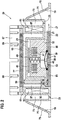
- FIG. 2 shows the functional unit 20 according to the invention.
- the functional unit 20 comprises a plurality of assemblies, such as a diaphragm pump designed as a pumping device 41, a heating element 63, a réelleleitmaschine 61, which terminates at the top with a heat conducting ring 67, a filter screen 65, a valve plate 35 and a (vent) fireplace 59th
- the functional unit 20 is inserted from below into a preferably circular opening of the storage tank 19 and then sealed by a weld 33 with the storage tank 19.
- the functional unit 20 is composed of three main components. It is a housing 21 having a cavity 23, a pump body 32 and a valve plate 35th
- the downwardly open cavity 23 is formed in the center of the housing 21, the downwardly open cavity 23 is formed.
- the pump body 32 is arranged in the cavity 23, the pump body 32 is arranged in the cavity 23, the pump body 32 is arranged.
- the cavity 23 is completed by the valve plate 35th
- a diaphragm 43 and the electromagnetic drive with an armature 45 and an electromagnet 47 are arranged in the pump body 32 .
- the diaphragm 43 is moved by the armature 45 by means of an electromagnet 47.
- the electromagnet 47 attracts the armature 45 against the spring force of a spring element 49.
- the working diaphragm 43 undergoes an up and down movement by turning on and off a current flowing through the electromagnet 47.
- reducing agent is conveyed from a working space 50 of the pumping device 41 into the delivery line 22; during the upward movement, reducing agent is sucked into the working area 50 through a suction line 51 arranged in the valve plate 35.
- valve plate 35 is in FIG. 2 integrated on the right side of the delivery line 22 for the liquid reducing agent.
- a first check valve 39 is arranged in the delivery line 22 in the delivery line 22.
- valve plate 35 is in FIG. 2 integrated on the left side of a suction line 51.
- a second check valve 53 is arranged in the suction line 51.
- the suction line 51 bends at the in FIG. 2 left end perpendicular to the top.
- the bent portion of the suction pipe 51 continues in the pump body 32 and in the pump housing 21.
- the extending in the vertical direction of the suction line in the housing 21 has the reference numeral 59 and is hereinafter referred to as a fireplace.
- the chimney 59 terminates shortly below a filter element 65.
- the filter element 65 is preferably designed as a close-meshed filter fabric and is sealingly connected at its outer edge with a heat distribution body 61.
- the suction line 51 is hydraulically connected to a first liquid reservoir 57.
- the first liquid reservoir 57 is bounded in the radial direction by a heating element 63 or a heat distribution body 61 and the cavity 23.
- FIG. 2 a liquid level of the urea-water solution is located. If the liquid level drops further than in FIG. 2 represented, then the upper end of the chimney protrudes into the air bubble located below the filter element 65.
- the diaphragm pump 41 When the diaphragm pump 41 is turned on in this state, the diaphragm pump 41 sucks through the throttle 55 the urea-water solution present in the first fluid reservoir 57. At the same time, the diaphragm pump 41 sucks air through the chimney 59. In this case, the urea-water solution and the air mix to form a two-phase mixture, which is conveyed by the diaphragm pump 41.
- the filter material is partially hydrophobic and allows little or no air through. Thus, air accumulates below the filter cloth. Some of this air was previously dissolved in the liquid or enters the system through the re-suction process to vent the system with Hilde of the 4/2 valve 99. The vacuuming takes place each time the vehicle is parked to prevent freeze damage. However, this also means that air is below filter 65 every time the vehicle is started. Without the chimney 59 and the throttle 55, the entire space 57 would fill with air over time. If the pump then sucks, reducing agent passes through the filter cloth 65 into the room 57. This would lead to uncontrolled aspiration, especially if, for example, when cornering or downhill, liquid reducing agent spills into the interior of the heat conducting ring 67.
- the heat distribution body 61 is preferably made of aluminum, although other materials can be used. In the heat distribution body 61, one or more PTC heating elements 63 are pressed. The heating elements 63 and / or the heat distribution body 61 may be coated with plastic to protect against corrosion.
- the heat-conducting body 61 goes up into a heat-conducting ring 67.
- the heat conducting body 61 and the heat conducting ring 67 support the heat transfer from the heating elements 63 to the urea-water solution.
- the casseroleleitring 67 has recesses 69, which are preferably directed sloping inwards sloping.
- the recesses 69 terminate in the interior of the heat-conducting ring 67 slightly above the filter element 65, so that the liquid reducing agent can reach the interior of the heat-conducting ring and the filter element 65, for example when driving uphill.
- the storage tank 19 forms a circumferential wall 71, which forms a further reservoir 73 with the outer wall of the heat distribution body 61.
- the second reservoir 73 has, inter alia, the function of a swirl pot.
- To the storage tank 19 is followed by the circumferential wall 71 at an inclined ramp 75, which limits the second reservoir 73.
- liquid reducing agent If liquid reducing agent is present in the storage tank, it passes through the filter element 65 into the first reservoir 57 and can be conveyed by the diaphragm pump 41 as required. This is done by 43 reducing agent is sucked from the reservoir 57 via the inlet line 51 into the work area 50 by lifting the working diaphragm 43 if necessary. By switching on the current for the electromagnet 47, the working diaphragm 43 is moved downwards via the magnet armature 45. As a result, reducing agent is conveyed through the delivery line 22 to the metering device 13.
- the reducing agent at low filling level can pass from the storage tank 19 via the ramp 75 into the second reservoir 73. From there, the reducing agent passes through the recesses 69 of the sauceleitrings 67 into the first reservoir 57. From the reservoir 57, the reducing agent is conveyed in the manner described above by the diaphragm pump 41.
- the reducing agent freezes slowly from below and outside.
- the reducing agent must be heated or thawed.
- the heating elements 63 in the cylindrical heat distribution body 61 on the other hand, the discharged heat of the electromagnet 47 can be used as a heater.
- the pumping device 41 is arranged so that the electromagnet 47 is arranged in the upper region of the functional unit 20.
- valve plate 35 closes down the functional unit 20 from plan. By this arrangement it is ensured that frost first the valve plate 35 freezes, while the area above it, in particular by the position of the heating electromagnet 47 and the heat distribution body 61 only later freezes. With such a bottom-up freezing, ice pressure can not build up because the reductant can continuously escape up to below the filter element 65.
- an air bubble 77 is present below the filter element 65, because the excreted from the reducing agent air can not escape through the close-meshed filter element 65 upwards.
- This compressible air bubble 77 absorbs the expansion of the reducing agent during the transition from the liquid phase to the solid phase and thereby prevents the functional unit 20 from being damaged by ice pressure.
- the inventive design of the functional unit 20 is characterized by a high rigidity due to the cylindrical heat distribution body 61.
- the deformation-critical pumping unit 41 and a sealing point of the valve plate 35 to the storage tank 19 are in the interior by the cylindrical heat distribution body 61 before Damage protected because the reducing agent freezes from bottom to top and the air bubble 77 absorbs the increase in volume of the freezing reducing agent.
- the peripheral wall 71 in the bottom of the storage tank makes it very soft in the radial direction, so that any deformations occurring in the wall 71 of the storage tank 19 and not take place in the functional unit 20.
Claims (12)
- Unité fonctionnelle (20) pour un réservoir (19) pour un agent réducteur fluide, l'unité fonctionnelle (20) pouvant être prévue dans le fond du réservoir (19), comprenant un dispositif de pompe (41) qui est prévu pour refouler l'agent réducteur hors du réservoir (19),
caractérisée en ce qu'entre une ouverture qui est réalisée dans une portion verticale d'une conduite d'aspiration (51) et une extrémité inférieure d'une cheminée (59) disposée sensiblement verticalement, est prévue une fente (55) agissant tant qu'étranglement,
la conduite d'aspiration étant connectée hydrauliquement par le biais de la fente (55) à un premier contenant de stockage (57) d'agent réducteur et la cheminée (59) se terminant juste en dessous d'un élément de filtre (65) et étant prévue pour aspirer de l'air qui peut s'accumuler en dessous de l'élément de filtre (65). - Unité fonctionnelle (20) selon la revendication 1,
caractérisée en ce qu'elle peut être insérée dans une ouverture dans le fond du réservoir (19) et peut être connectée de manière hermétique au réservoir (19). - Unité fonctionnelle (20) selon la revendication 1 ou 2, caractérisée en ce qu'elle comprend au moins un boîtier (21), un corps de pompe (32) et une plaque de soupape (35).
- Unité fonctionnelle (20) selon la revendication 3,
caractérisée en ce qu'une conduite d'aspiration (51) et une conduite de refoulement (22) sont réalisées dans la plaque de soupape (35). - Unité fonctionnelle (20) selon l'une quelconque des revendications caractérisée en ce que le dispositif de pompe (41) comprend un induit (45), un électroaimant (47), une membrane (43) et une, ou la, plaque de soupape (35).
- Unité fonctionnelle (20) selon l'une quelconque des revendications précédentes, caractérisée en ce qu'elle peut être chauffée par un élément chauffant (63), un corps thermoconducteur (61) et/ou une bague thermoconductrice (67).
- Unité fonctionnelle (20) selon la revendication 6,
caractérisée en ce que le corps thermoconducteur (61) et/ou la bague thermoconductrice (67) sont réalisés essentiellement sous forme cylindrique. - Unité fonctionnelle (20) selon l'une quelconque des revendications précédentes, caractérisée en ce qu'à l'extrémité supérieure du corps thermoconducteur (61) est monté de manière hermétique l'élément de filtre (65) réalisé sous forme de tissu filtrant.
- Unité fonctionnelle (20) selon l'une quelconque des revendications 6 à 8, caractérisée en ce que la bague thermoconductrice (67) présente des évidements (69) qui reçoivent le liquide clapotant dans le réservoir (19) pendant la conduite.
- Unité fonctionnelle (20) selon l'une quelconque des revendications 6 à 9, caractérisée en ce que le corps thermoconducteur (61) limite le premier réservoir (57) pour agent réducteur.
- Unité fonctionnelle (20) selon l'une quelconque des revendications précédentes, caractérisée en ce qu'une bulle d'air (77) se forme pendant le fonctionnement en dessous de l'élément de filtre (65).
- Réservoir (19) pour un agent réducteur fluide, une unité fonctionnelle (20) selon l'une quelconque des revendications précédentes étant prévue dans le fond du réservoir (19).
Applications Claiming Priority (2)
| Application Number | Priority Date | Filing Date | Title |
|---|---|---|---|
| DE102011075726A DE102011075726A1 (de) | 2011-05-12 | 2011-05-12 | Vorratstank und Funktionseinheit hierzu |
| PCT/EP2012/055314 WO2012152498A1 (fr) | 2011-05-12 | 2012-03-26 | Réservoir de stockage et unité fonctionnelle pour ledit réservoir |
Publications (2)
| Publication Number | Publication Date |
|---|---|
| EP2707579A1 EP2707579A1 (fr) | 2014-03-19 |
| EP2707579B1 true EP2707579B1 (fr) | 2018-07-04 |
Family
ID=45928878
Family Applications (1)
| Application Number | Title | Priority Date | Filing Date |
|---|---|---|---|
| EP12711852.9A Not-in-force EP2707579B1 (fr) | 2011-05-12 | 2012-03-26 | Réservoir de stockage et unité fonctionnelle pour ledit réservoir |
Country Status (4)
| Country | Link |
|---|---|
| EP (1) | EP2707579B1 (fr) |
| CN (1) | CN103518046B (fr) |
| DE (1) | DE102011075726A1 (fr) |
| WO (1) | WO2012152498A1 (fr) |
Families Citing this family (11)
| Publication number | Priority date | Publication date | Assignee | Title |
|---|---|---|---|---|
| DE102012204402B4 (de) | 2012-03-20 | 2020-01-02 | Robert Bosch Gmbh | Elektronisches Schaltungsmodul zur Steuerung einer Hubmagnetmembranpumpe und Verfahren zum Betreiben der Hubmagnetmembranpumpe |
| DE102013101573A1 (de) | 2013-02-18 | 2014-08-21 | Emitec France S.A.S | Verfahren zum Beheizen einer Fördervorrichtung |
| DE102013108501A1 (de) | 2013-08-07 | 2015-03-05 | Emitec Gesellschaft Für Emissionstechnologie Mbh | Verfahren zur Herstellung eines Fördermoduls zum Einbau in einen Tank |
| US9957862B2 (en) | 2014-04-03 | 2018-05-01 | Robert Bosch Gmbh | Secondary heating device for diesel exhaust fluid tank |
| DE102014222743A1 (de) * | 2014-11-06 | 2016-05-12 | Continental Automotive Gmbh | Pumpeneinheit für Reduktionsmittel einer Abgasreinigungsanlage |
| DE102015206589A1 (de) * | 2015-04-14 | 2016-10-20 | Continental Automotive Gmbh | Verfahren zum Bestimmen einer Temperatur einer Membran einer Pumpe |
| US10634033B2 (en) | 2015-12-10 | 2020-04-28 | Continental Automotive Gmbh | Tank system for a reducing agent |
| EP3428438A1 (fr) * | 2017-07-13 | 2019-01-16 | Kautex Textron GmbH & Co. Kg | Récipient pour liquide avec dispositif de chauffage |
| DE102017222301A1 (de) | 2017-12-08 | 2019-06-13 | Continental Automotive Gmbh | SCR-Dosiereinheit zur Förderung und Bereitstellung eines flüssigen Abgasreinigungsadditivs |
| DE102018117181A1 (de) * | 2018-07-16 | 2020-01-16 | Kautex Textron Gmbh & Co. Kg | Flüssigkeitsbehälter für ein Kraftfahrzeug und Verfahren zum Herstellen eines Flüssigkeitsbehälters für ein Kraftfahrzeug |
| FR3096738B1 (fr) * | 2019-05-31 | 2021-05-28 | Plastic Omnium Advanced Innovation & Res | Dispositif de fixation pour module de distribution de solution aqueuse contenue dans un réservoir à bord d’un véhicule automobile |
Family Cites Families (7)
| Publication number | Priority date | Publication date | Assignee | Title |
|---|---|---|---|---|
| DE102005037201A1 (de) * | 2005-08-06 | 2007-02-22 | Eichenauer Heizelemente Gmbh & Co. Kg | Heizsystem |
| US20100050606A1 (en) * | 2008-09-04 | 2010-03-04 | Fulks Gary C | Urea tank assembly |
| DE102009000101A1 (de) * | 2009-01-09 | 2010-07-15 | Robert Bosch Gmbh | Tankgestaltung |
| DE102010004614A1 (de) * | 2010-01-13 | 2011-07-14 | Emitec Gesellschaft für Emissionstechnologie mbH, 53797 | Tankanordnung und Dosiersystem für ein Reduktionsmittel |
| CN201666176U (zh) * | 2010-03-05 | 2010-12-08 | 苏州派格力减排系统有限公司 | 柴油车用储液罐加压式尿素溶液计量喷射系统 |
| DE102010003310A1 (de) * | 2010-03-26 | 2011-09-29 | Robert Bosch Gmbh | Vorrichtung zur Vermeidung des Flutens eines Förder- oder Dosiersystems |
| DE102010029636A1 (de) * | 2010-06-02 | 2011-12-08 | Robert Bosch Gmbh | Vorratsbehälter für Flüssigkeiten mit einem Flüssigkeitssumpf für ein Kraftfahrzeug |
-
2011
- 2011-05-12 DE DE102011075726A patent/DE102011075726A1/de not_active Withdrawn
-
2012
- 2012-03-26 CN CN201280022686.3A patent/CN103518046B/zh not_active Expired - Fee Related
- 2012-03-26 EP EP12711852.9A patent/EP2707579B1/fr not_active Not-in-force
- 2012-03-26 WO PCT/EP2012/055314 patent/WO2012152498A1/fr active Application Filing
Non-Patent Citations (1)
| Title |
|---|
| None * |
Also Published As
| Publication number | Publication date |
|---|---|
| WO2012152498A1 (fr) | 2012-11-15 |
| DE102011075726A1 (de) | 2012-11-15 |
| CN103518046B (zh) | 2016-06-29 |
| EP2707579A1 (fr) | 2014-03-19 |
| CN103518046A (zh) | 2014-01-15 |
Similar Documents
| Publication | Publication Date | Title |
|---|---|---|
| EP2707579B1 (fr) | Réservoir de stockage et unité fonctionnelle pour ledit réservoir | |
| EP2453115B1 (fr) | Réservoir de liquide, en particulier pour une solution d'urée aqueuse | |
| EP1925354B1 (fr) | Dispositif de réduction catalytique | |
| EP2094953B1 (fr) | Dispositif de dosage d'agent de réduction liquide | |
| EP2569522B1 (fr) | Dispositif de réduction de substances polluantes dans le flux de gaz d'échappement d'un moteur à combustion interne | |
| EP2157295B1 (fr) | Système de dosage pour un milieu liquide, notamment solution urée-eau | |
| DE102005002318A1 (de) | Abgasnachbehandlungsverfahren und Vorrichtung hierzu | |
| WO2009121644A1 (fr) | Dispositif de dosage d'un agent de réduction liquide | |
| DE102006061734A1 (de) | Vorrichtung zum Dosieren eines Reduktionsmittels | |
| DE102013210742A1 (de) | Tankvorrichtung | |
| EP2288795B1 (fr) | Systeme scr dote de plusieurs reservoirs | |
| WO2010046152A1 (fr) | Système de dosage pour un fluide liquide, en particulier pour une solution d'eau et d'urée | |
| EP3325782B1 (fr) | Soupape d'injection et système de post-traitement des gaz d'échappement | |
| DE102007033470B4 (de) | Vorrichtung und Verfahren zur Dosierung eines Reduktionsmittels in einen Abgastrakt eines Fahrzeugs | |
| DE102009011018A1 (de) | Vorrichtung zum Zuführen eines Hilfsmittels zu einer Abgasnachbehandlungseinrichtung eines Kraftfahrzeugs | |
| DE102009054735A1 (de) | Verfahren zum Betreiben eines SCR-Katalysatorsystems | |
| WO2016142107A1 (fr) | Récipient pour carburant liquide d'un véhicule automobile et véhicule automobile équipé d'un tel récipient | |
| EP2577010B1 (fr) | Dispositif de stockage de fluide | |
| WO2018121908A1 (fr) | Ensemble réservoir pour véhicule | |
| DE102010039115A1 (de) | Vorratstank für flüssiges Reduktionsmittel | |
| DE102021102696A1 (de) | Behälter für ein flüssiges Betriebsmittel eines Kraftfahrzeuges und Kraftfahrzeug mit einem solchen Behälter | |
| WO2020038640A1 (fr) | Système de réservoir | |
| EP2450541A1 (fr) | Agencement de réservoir | |
| WO2018103923A1 (fr) | Dispositif d'injection d'agent de réduction | |
| DE102016224237A1 (de) | Reduktionsmittel-Einspritzvorrichtung |
Legal Events
| Date | Code | Title | Description |
|---|---|---|---|
| PUAI | Public reference made under article 153(3) epc to a published international application that has entered the european phase |
Free format text: ORIGINAL CODE: 0009012 |
|
| 17P | Request for examination filed |
Effective date: 20131212 |
|
| AK | Designated contracting states |
Kind code of ref document: A1 Designated state(s): AL AT BE BG CH CY CZ DE DK EE ES FI FR GB GR HR HU IE IS IT LI LT LU LV MC MK MT NL NO PL PT RO RS SE SI SK SM TR |
|
| DAX | Request for extension of the european patent (deleted) | ||
| STAA | Information on the status of an ep patent application or granted ep patent |
Free format text: STATUS: EXAMINATION IS IN PROGRESS |
|
| 17Q | First examination report despatched |
Effective date: 20171114 |
|
| GRAP | Despatch of communication of intention to grant a patent |
Free format text: ORIGINAL CODE: EPIDOSNIGR1 |
|
| STAA | Information on the status of an ep patent application or granted ep patent |
Free format text: STATUS: GRANT OF PATENT IS INTENDED |
|
| INTG | Intention to grant announced |
Effective date: 20180404 |
|
| GRAS | Grant fee paid |
Free format text: ORIGINAL CODE: EPIDOSNIGR3 |
|
| GRAA | (expected) grant |
Free format text: ORIGINAL CODE: 0009210 |
|
| STAA | Information on the status of an ep patent application or granted ep patent |
Free format text: STATUS: THE PATENT HAS BEEN GRANTED |
|
| AK | Designated contracting states |
Kind code of ref document: B1 Designated state(s): AL AT BE BG CH CY CZ DE DK EE ES FI FR GB GR HR HU IE IS IT LI LT LU LV MC MK MT NL NO PL PT RO RS SE SI SK SM TR |
|
| REG | Reference to a national code |
Ref country code: GB Ref legal event code: FG4D Free format text: NOT ENGLISH |
|
| REG | Reference to a national code |
Ref country code: CH Ref legal event code: EP |
|
| REG | Reference to a national code |
Ref country code: AT Ref legal event code: REF Ref document number: 1014744 Country of ref document: AT Kind code of ref document: T Effective date: 20180715 |
|
| REG | Reference to a national code |
Ref country code: IE Ref legal event code: FG4D Free format text: LANGUAGE OF EP DOCUMENT: GERMAN |
|
| REG | Reference to a national code |
Ref country code: DE Ref legal event code: R096 Ref document number: 502012012979 Country of ref document: DE |
|
| REG | Reference to a national code |
Ref country code: NL Ref legal event code: MP Effective date: 20180704 |
|
| REG | Reference to a national code |
Ref country code: LT Ref legal event code: MG4D |
|
| PG25 | Lapsed in a contracting state [announced via postgrant information from national office to epo] |
Ref country code: NL Free format text: LAPSE BECAUSE OF FAILURE TO SUBMIT A TRANSLATION OF THE DESCRIPTION OR TO PAY THE FEE WITHIN THE PRESCRIBED TIME-LIMIT Effective date: 20180704 |
|
| PG25 | Lapsed in a contracting state [announced via postgrant information from national office to epo] |
Ref country code: CZ Free format text: LAPSE BECAUSE OF FAILURE TO SUBMIT A TRANSLATION OF THE DESCRIPTION OR TO PAY THE FEE WITHIN THE PRESCRIBED TIME-LIMIT Effective date: 20180704 Ref country code: PL Free format text: LAPSE BECAUSE OF FAILURE TO SUBMIT A TRANSLATION OF THE DESCRIPTION OR TO PAY THE FEE WITHIN THE PRESCRIBED TIME-LIMIT Effective date: 20180704 Ref country code: LT Free format text: LAPSE BECAUSE OF FAILURE TO SUBMIT A TRANSLATION OF THE DESCRIPTION OR TO PAY THE FEE WITHIN THE PRESCRIBED TIME-LIMIT Effective date: 20180704 Ref country code: BG Free format text: LAPSE BECAUSE OF FAILURE TO SUBMIT A TRANSLATION OF THE DESCRIPTION OR TO PAY THE FEE WITHIN THE PRESCRIBED TIME-LIMIT Effective date: 20181004 Ref country code: SE Free format text: LAPSE BECAUSE OF FAILURE TO SUBMIT A TRANSLATION OF THE DESCRIPTION OR TO PAY THE FEE WITHIN THE PRESCRIBED TIME-LIMIT Effective date: 20180704 Ref country code: IS Free format text: LAPSE BECAUSE OF FAILURE TO SUBMIT A TRANSLATION OF THE DESCRIPTION OR TO PAY THE FEE WITHIN THE PRESCRIBED TIME-LIMIT Effective date: 20181104 Ref country code: NO Free format text: LAPSE BECAUSE OF FAILURE TO SUBMIT A TRANSLATION OF THE DESCRIPTION OR TO PAY THE FEE WITHIN THE PRESCRIBED TIME-LIMIT Effective date: 20181004 Ref country code: FI Free format text: LAPSE BECAUSE OF FAILURE TO SUBMIT A TRANSLATION OF THE DESCRIPTION OR TO PAY THE FEE WITHIN THE PRESCRIBED TIME-LIMIT Effective date: 20180704 Ref country code: GR Free format text: LAPSE BECAUSE OF FAILURE TO SUBMIT A TRANSLATION OF THE DESCRIPTION OR TO PAY THE FEE WITHIN THE PRESCRIBED TIME-LIMIT Effective date: 20181005 Ref country code: RS Free format text: LAPSE BECAUSE OF FAILURE TO SUBMIT A TRANSLATION OF THE DESCRIPTION OR TO PAY THE FEE WITHIN THE PRESCRIBED TIME-LIMIT Effective date: 20180704 |
|
| PG25 | Lapsed in a contracting state [announced via postgrant information from national office to epo] |
Ref country code: LV Free format text: LAPSE BECAUSE OF FAILURE TO SUBMIT A TRANSLATION OF THE DESCRIPTION OR TO PAY THE FEE WITHIN THE PRESCRIBED TIME-LIMIT Effective date: 20180704 Ref country code: ES Free format text: LAPSE BECAUSE OF FAILURE TO SUBMIT A TRANSLATION OF THE DESCRIPTION OR TO PAY THE FEE WITHIN THE PRESCRIBED TIME-LIMIT Effective date: 20180704 Ref country code: HR Free format text: LAPSE BECAUSE OF FAILURE TO SUBMIT A TRANSLATION OF THE DESCRIPTION OR TO PAY THE FEE WITHIN THE PRESCRIBED TIME-LIMIT Effective date: 20180704 Ref country code: AL Free format text: LAPSE BECAUSE OF FAILURE TO SUBMIT A TRANSLATION OF THE DESCRIPTION OR TO PAY THE FEE WITHIN THE PRESCRIBED TIME-LIMIT Effective date: 20180704 |
|
| REG | Reference to a national code |
Ref country code: DE Ref legal event code: R097 Ref document number: 502012012979 Country of ref document: DE |
|
| PG25 | Lapsed in a contracting state [announced via postgrant information from national office to epo] |
Ref country code: EE Free format text: LAPSE BECAUSE OF FAILURE TO SUBMIT A TRANSLATION OF THE DESCRIPTION OR TO PAY THE FEE WITHIN THE PRESCRIBED TIME-LIMIT Effective date: 20180704 Ref country code: IT Free format text: LAPSE BECAUSE OF FAILURE TO SUBMIT A TRANSLATION OF THE DESCRIPTION OR TO PAY THE FEE WITHIN THE PRESCRIBED TIME-LIMIT Effective date: 20180704 Ref country code: RO Free format text: LAPSE BECAUSE OF FAILURE TO SUBMIT A TRANSLATION OF THE DESCRIPTION OR TO PAY THE FEE WITHIN THE PRESCRIBED TIME-LIMIT Effective date: 20180704 |
|
| PLBE | No opposition filed within time limit |
Free format text: ORIGINAL CODE: 0009261 |
|
| STAA | Information on the status of an ep patent application or granted ep patent |
Free format text: STATUS: NO OPPOSITION FILED WITHIN TIME LIMIT |
|
| PG25 | Lapsed in a contracting state [announced via postgrant information from national office to epo] |
Ref country code: SK Free format text: LAPSE BECAUSE OF FAILURE TO SUBMIT A TRANSLATION OF THE DESCRIPTION OR TO PAY THE FEE WITHIN THE PRESCRIBED TIME-LIMIT Effective date: 20180704 Ref country code: SM Free format text: LAPSE BECAUSE OF FAILURE TO SUBMIT A TRANSLATION OF THE DESCRIPTION OR TO PAY THE FEE WITHIN THE PRESCRIBED TIME-LIMIT Effective date: 20180704 Ref country code: DK Free format text: LAPSE BECAUSE OF FAILURE TO SUBMIT A TRANSLATION OF THE DESCRIPTION OR TO PAY THE FEE WITHIN THE PRESCRIBED TIME-LIMIT Effective date: 20180704 |
|
| 26N | No opposition filed |
Effective date: 20190405 |
|
| PG25 | Lapsed in a contracting state [announced via postgrant information from national office to epo] |
Ref country code: SI Free format text: LAPSE BECAUSE OF FAILURE TO SUBMIT A TRANSLATION OF THE DESCRIPTION OR TO PAY THE FEE WITHIN THE PRESCRIBED TIME-LIMIT Effective date: 20180704 |
|
| PG25 | Lapsed in a contracting state [announced via postgrant information from national office to epo] |
Ref country code: MC Free format text: LAPSE BECAUSE OF FAILURE TO SUBMIT A TRANSLATION OF THE DESCRIPTION OR TO PAY THE FEE WITHIN THE PRESCRIBED TIME-LIMIT Effective date: 20180704 |
|
| REG | Reference to a national code |
Ref country code: CH Ref legal event code: PL |
|
| GBPC | Gb: european patent ceased through non-payment of renewal fee |
Effective date: 20190326 |
|
| PG25 | Lapsed in a contracting state [announced via postgrant information from national office to epo] |
Ref country code: LU Free format text: LAPSE BECAUSE OF NON-PAYMENT OF DUE FEES Effective date: 20190326 |
|
| REG | Reference to a national code |
Ref country code: BE Ref legal event code: MM Effective date: 20190331 |
|
| PG25 | Lapsed in a contracting state [announced via postgrant information from national office to epo] |
Ref country code: LI Free format text: LAPSE BECAUSE OF NON-PAYMENT OF DUE FEES Effective date: 20190331 Ref country code: CH Free format text: LAPSE BECAUSE OF NON-PAYMENT OF DUE FEES Effective date: 20190331 Ref country code: GB Free format text: LAPSE BECAUSE OF NON-PAYMENT OF DUE FEES Effective date: 20190326 Ref country code: IE Free format text: LAPSE BECAUSE OF NON-PAYMENT OF DUE FEES Effective date: 20190326 |
|
| PG25 | Lapsed in a contracting state [announced via postgrant information from national office to epo] |
Ref country code: BE Free format text: LAPSE BECAUSE OF NON-PAYMENT OF DUE FEES Effective date: 20190331 |
|
| PG25 | Lapsed in a contracting state [announced via postgrant information from national office to epo] |
Ref country code: TR Free format text: LAPSE BECAUSE OF FAILURE TO SUBMIT A TRANSLATION OF THE DESCRIPTION OR TO PAY THE FEE WITHIN THE PRESCRIBED TIME-LIMIT Effective date: 20180704 |
|
| PG25 | Lapsed in a contracting state [announced via postgrant information from national office to epo] |
Ref country code: PT Free format text: LAPSE BECAUSE OF FAILURE TO SUBMIT A TRANSLATION OF THE DESCRIPTION OR TO PAY THE FEE WITHIN THE PRESCRIBED TIME-LIMIT Effective date: 20181105 Ref country code: MT Free format text: LAPSE BECAUSE OF FAILURE TO SUBMIT A TRANSLATION OF THE DESCRIPTION OR TO PAY THE FEE WITHIN THE PRESCRIBED TIME-LIMIT Effective date: 20180704 |
|
| PGFP | Annual fee paid to national office [announced via postgrant information from national office to epo] |
Ref country code: FR Payment date: 20200325 Year of fee payment: 9 |
|
| PGFP | Annual fee paid to national office [announced via postgrant information from national office to epo] |
Ref country code: DE Payment date: 20200526 Year of fee payment: 9 |
|
| REG | Reference to a national code |
Ref country code: AT Ref legal event code: MM01 Ref document number: 1014744 Country of ref document: AT Kind code of ref document: T Effective date: 20190326 |
|
| PG25 | Lapsed in a contracting state [announced via postgrant information from national office to epo] |
Ref country code: AT Free format text: LAPSE BECAUSE OF NON-PAYMENT OF DUE FEES Effective date: 20190326 |
|
| PG25 | Lapsed in a contracting state [announced via postgrant information from national office to epo] |
Ref country code: CY Free format text: LAPSE BECAUSE OF FAILURE TO SUBMIT A TRANSLATION OF THE DESCRIPTION OR TO PAY THE FEE WITHIN THE PRESCRIBED TIME-LIMIT Effective date: 20180704 |
|
| PG25 | Lapsed in a contracting state [announced via postgrant information from national office to epo] |
Ref country code: HU Free format text: LAPSE BECAUSE OF FAILURE TO SUBMIT A TRANSLATION OF THE DESCRIPTION OR TO PAY THE FEE WITHIN THE PRESCRIBED TIME-LIMIT; INVALID AB INITIO Effective date: 20120326 |
|
| REG | Reference to a national code |
Ref country code: DE Ref legal event code: R119 Ref document number: 502012012979 Country of ref document: DE |
|
| PG25 | Lapsed in a contracting state [announced via postgrant information from national office to epo] |
Ref country code: DE Free format text: LAPSE BECAUSE OF NON-PAYMENT OF DUE FEES Effective date: 20211001 Ref country code: FR Free format text: LAPSE BECAUSE OF NON-PAYMENT OF DUE FEES Effective date: 20210331 |
|
| PG25 | Lapsed in a contracting state [announced via postgrant information from national office to epo] |
Ref country code: MK Free format text: LAPSE BECAUSE OF FAILURE TO SUBMIT A TRANSLATION OF THE DESCRIPTION OR TO PAY THE FEE WITHIN THE PRESCRIBED TIME-LIMIT Effective date: 20180704 |