EP2707579B1 - Vorratstank und funktionseinheit hierzu - Google Patents
Vorratstank und funktionseinheit hierzu Download PDFInfo
- Publication number
- EP2707579B1 EP2707579B1 EP12711852.9A EP12711852A EP2707579B1 EP 2707579 B1 EP2707579 B1 EP 2707579B1 EP 12711852 A EP12711852 A EP 12711852A EP 2707579 B1 EP2707579 B1 EP 2707579B1
- Authority
- EP
- European Patent Office
- Prior art keywords
- functional unit
- storage tank
- reducing agent
- heat conducting
- reservoir
- Prior art date
- Legal status (The legal status is an assumption and is not a legal conclusion. Google has not performed a legal analysis and makes no representation as to the accuracy of the status listed.)
- Not-in-force
Links
Images

Classifications
-
- F—MECHANICAL ENGINEERING; LIGHTING; HEATING; WEAPONS; BLASTING
- F01—MACHINES OR ENGINES IN GENERAL; ENGINE PLANTS IN GENERAL; STEAM ENGINES
- F01N—GAS-FLOW SILENCERS OR EXHAUST APPARATUS FOR MACHINES OR ENGINES IN GENERAL; GAS-FLOW SILENCERS OR EXHAUST APPARATUS FOR INTERNAL COMBUSTION ENGINES
- F01N3/00—Exhaust or silencing apparatus having means for purifying, rendering innocuous, or otherwise treating exhaust
- F01N3/08—Exhaust or silencing apparatus having means for purifying, rendering innocuous, or otherwise treating exhaust for rendering innocuous
- F01N3/10—Exhaust or silencing apparatus having means for purifying, rendering innocuous, or otherwise treating exhaust for rendering innocuous by thermal or catalytic conversion of noxious components of exhaust
- F01N3/18—Exhaust or silencing apparatus having means for purifying, rendering innocuous, or otherwise treating exhaust for rendering innocuous by thermal or catalytic conversion of noxious components of exhaust characterised by methods of operation; Control
- F01N3/20—Exhaust or silencing apparatus having means for purifying, rendering innocuous, or otherwise treating exhaust for rendering innocuous by thermal or catalytic conversion of noxious components of exhaust characterised by methods of operation; Control specially adapted for catalytic conversion ; Methods of operation or control of catalytic converters
- F01N3/2066—Selective catalytic reduction [SCR]
-
- F—MECHANICAL ENGINEERING; LIGHTING; HEATING; WEAPONS; BLASTING
- F01—MACHINES OR ENGINES IN GENERAL; ENGINE PLANTS IN GENERAL; STEAM ENGINES
- F01N—GAS-FLOW SILENCERS OR EXHAUST APPARATUS FOR MACHINES OR ENGINES IN GENERAL; GAS-FLOW SILENCERS OR EXHAUST APPARATUS FOR INTERNAL COMBUSTION ENGINES
- F01N2610/00—Adding substances to exhaust gases
- F01N2610/02—Adding substances to exhaust gases the substance being ammonia or urea
-
- F—MECHANICAL ENGINEERING; LIGHTING; HEATING; WEAPONS; BLASTING
- F01—MACHINES OR ENGINES IN GENERAL; ENGINE PLANTS IN GENERAL; STEAM ENGINES
- F01N—GAS-FLOW SILENCERS OR EXHAUST APPARATUS FOR MACHINES OR ENGINES IN GENERAL; GAS-FLOW SILENCERS OR EXHAUST APPARATUS FOR INTERNAL COMBUSTION ENGINES
- F01N2610/00—Adding substances to exhaust gases
- F01N2610/10—Adding substances to exhaust gases the substance being heated, e.g. by heating tank or supply line of the added substance
-
- F—MECHANICAL ENGINEERING; LIGHTING; HEATING; WEAPONS; BLASTING
- F01—MACHINES OR ENGINES IN GENERAL; ENGINE PLANTS IN GENERAL; STEAM ENGINES
- F01N—GAS-FLOW SILENCERS OR EXHAUST APPARATUS FOR MACHINES OR ENGINES IN GENERAL; GAS-FLOW SILENCERS OR EXHAUST APPARATUS FOR INTERNAL COMBUSTION ENGINES
- F01N2610/00—Adding substances to exhaust gases
- F01N2610/14—Arrangements for the supply of substances, e.g. conduits
- F01N2610/1406—Storage means for substances, e.g. tanks or reservoirs
-
- F—MECHANICAL ENGINEERING; LIGHTING; HEATING; WEAPONS; BLASTING
- F01—MACHINES OR ENGINES IN GENERAL; ENGINE PLANTS IN GENERAL; STEAM ENGINES
- F01N—GAS-FLOW SILENCERS OR EXHAUST APPARATUS FOR MACHINES OR ENGINES IN GENERAL; GAS-FLOW SILENCERS OR EXHAUST APPARATUS FOR INTERNAL COMBUSTION ENGINES
- F01N2610/00—Adding substances to exhaust gases
- F01N2610/14—Arrangements for the supply of substances, e.g. conduits
- F01N2610/1433—Pumps
-
- F—MECHANICAL ENGINEERING; LIGHTING; HEATING; WEAPONS; BLASTING
- F01—MACHINES OR ENGINES IN GENERAL; ENGINE PLANTS IN GENERAL; STEAM ENGINES
- F01N—GAS-FLOW SILENCERS OR EXHAUST APPARATUS FOR MACHINES OR ENGINES IN GENERAL; GAS-FLOW SILENCERS OR EXHAUST APPARATUS FOR INTERNAL COMBUSTION ENGINES
- F01N2610/00—Adding substances to exhaust gases
- F01N2610/14—Arrangements for the supply of substances, e.g. conduits
- F01N2610/1466—Means for venting air out of conduits or tanks
-
- Y—GENERAL TAGGING OF NEW TECHNOLOGICAL DEVELOPMENTS; GENERAL TAGGING OF CROSS-SECTIONAL TECHNOLOGIES SPANNING OVER SEVERAL SECTIONS OF THE IPC; TECHNICAL SUBJECTS COVERED BY FORMER USPC CROSS-REFERENCE ART COLLECTIONS [XRACs] AND DIGESTS
- Y02—TECHNOLOGIES OR APPLICATIONS FOR MITIGATION OR ADAPTATION AGAINST CLIMATE CHANGE
- Y02A—TECHNOLOGIES FOR ADAPTATION TO CLIMATE CHANGE
- Y02A50/00—TECHNOLOGIES FOR ADAPTATION TO CLIMATE CHANGE in human health protection, e.g. against extreme weather
- Y02A50/20—Air quality improvement or preservation, e.g. vehicle emission control or emission reduction by using catalytic converters
-
- Y—GENERAL TAGGING OF NEW TECHNOLOGICAL DEVELOPMENTS; GENERAL TAGGING OF CROSS-SECTIONAL TECHNOLOGIES SPANNING OVER SEVERAL SECTIONS OF THE IPC; TECHNICAL SUBJECTS COVERED BY FORMER USPC CROSS-REFERENCE ART COLLECTIONS [XRACs] AND DIGESTS
- Y02—TECHNOLOGIES OR APPLICATIONS FOR MITIGATION OR ADAPTATION AGAINST CLIMATE CHANGE
- Y02T—CLIMATE CHANGE MITIGATION TECHNOLOGIES RELATED TO TRANSPORTATION
- Y02T10/00—Road transport of goods or passengers
- Y02T10/10—Internal combustion engine [ICE] based vehicles
- Y02T10/12—Improving ICE efficiencies
Definitions
- the invention relates to a storage tank of an injection device according to the preamble of claim 1 and a functional unit for this purpose.
- a common method is a method with a catalyst for selective catalytic reduction (SCR), in which the harmful nitrogen oxide fraction in the exhaust gas is reduced to nitrogen and water with the aid of liquid reducing agent, for example a urea water solution (so-called AdBlue).
- SCR selective catalytic reduction
- AdBlue liquid reducing agent
- a pump usually promotes the reducing agent from a storage tank to a metering valve, which in turn injects the reducing agent in the exhaust gas.
- EP 2 161 422 A1 describes systems and methods for delivering a urea solution to an exhaust treatment system.
- a urea tank is provided.
- the urea tank includes a reservoir having a fluid inlet port for receiving urea solution and a fluid outlet port for discharging the urea solution.
- the urea tank further includes a vented hollow member disposed in the reservoir.
- the vented hollow member has an inner hollow portion and a plurality of openings that allow fluid flow between the reservoir and the inner hollow portion.
- the urea tank further includes a heater disposed along the hollow member to heat the urea solution in the inner hollow portion and in the reservoir.
- the urea tank further comprises a fluid pump disposed in the reservoir. The fluid pump is in fluid communication with the inner hollow portion and the reservoir to convey the urea solution therein through the fluid outlet port.
- WO 2010/078989 A1 discloses a storage tank for a metering system for introducing a reducing agent into an exhaust tract of an internal combustion engine.
- the storage tank has at least one opening for internals and openings for filling and emptying and for a ventilation / venting, all openings being arranged above a region of the storage tank flooded by the reducing agent.
- the present invention differs from the aforementioned prior art in that there is a gap acting as a throttle between the opening of a suction line (22) in the storage tank and a substantially vertical stack.
- the functional unit comprises a housing, a pump body and a valve plate, and that the functional unit is inserted into an opening in the bottom of the storage tank and sealingly connected to the storage tank.
- a suction line and a delivery line are formed in the valve plate.
- the heating device and any sensors can also be integrated into the functional unit, so that the functional unit according to the invention is compact and above all very flat. There are also advantageously no lines to the top of the storage tank needed.
- the housing of the functional unit is inserted from below into the storage tank and is welded to the storage tank. This ensures easy installation and the necessary tightness of the storage tank.
- the functional unit for conveying the reducing agent through the delivery line has a pumping device which comprises an electromagnet, a working diaphragm and the valve plate.
- the working diaphragm is preferably arranged in the region of the valve plate or an inlet of the delivery line; the electromagnet is preferably arranged in a region of the functional unit opposite the valve plate.
- An armature is disposed on the diaphragm, which can be moved by turning on and off a current through the electromagnet.
- the pumping device can therefore advantageously be constructed relatively flat in contrast to the known devices.
- valve elements support the respective function of the inflow and outflow into and out of the functional unit.
- a ventilation channel arranged in the functional device can provide the necessary ventilation, in particular in the region of the inflow.
- the functional unit can be heated by at least one heating device.
- Heaters are needed in the functional unit, so that the reducing agent can be kept liquid during frost, or can be thawed again after freezing when the vehicle is at a standstill.
- the heating device may comprise PTC heating elements, wherein the heating elements are preferably pressed into a cylindrical aluminum body.
- the aluminum body can be later encapsulated with plastic to avoid corrosion and represents a heat spreader.
- Other highly thermally conductive materials as an alternative to aluminum are of course also possible.
- the cylindrical heat distribution body can be designed so wide that it encloses substantially all components of the functional unit in order to heat or thaw the components of the functional unit when needed.
- the cylindrical aluminum body is characterized by a high rigidity, so that especially in the interior of the cylindrical aluminum body arranged pressure-sensitive components of the functional unit, such as the pumping means and the sealing areas of the valve plate to the storage tank, are sufficiently protected at an ice pressure in frost.
- the electromagnet Since the electromagnet is arranged more in the upper region of the functional unit, the heat generated during energization of the electromagnet is usable for devices of the functional unit, which in particular in the upper region of the functional unit, such. a filter element are arranged.
- the electromagnet thus represents, in addition to the heat distribution body, a second heating device within the functional unit.
- the functional unit for filtering the reducing agent introduced into the storage tank has a filter element, preferably a filter fabric, which is indirectly heatable.
- the filter fabric is here preferably formed so feinmaschig that particles of the reducing agent can be filtered out so that they can not clog the supply line or the delivery line.
- the filter fabric is usefully arranged in the upper part of the functional unit such that it essentially covers the functional unit and that the filter fabric can be heated by the electromagnet arranged in this region.
- the heating elements in the cylindrical heat distribution body can also conduct heat into the area of the filter fabric, so that it can be heated if necessary.
- the filter fabric can also be arranged undulating over the functional unit, so that a filter surface can be substantially enlarged. It is also possible that the filter fabric can be fixed exchangeably.
- the functional unit it is advantageous for the functional unit to have a heat-conducting ring on one side opposite the valve plate.
- the planteleitring ensures that the heat can be passed as best as possible, for example, to overlying ice of the storage tank.
- the plastic of the sheathing can support the heat transfer,
- the heat conduction ring ensures an optimal transfer of heat to the ice during thawing.
- the heat-conducting ring may have recesses on a side facing a storage tank cover, which can trap sloshing liquid reducing agent when the motor vehicle is driving in the storage tank. The recesses allow so that even with a low level of the reducing agent, the functional unit can have sufficient reducing agent in the interior for conveying.
- the functional unit comprises at least one reservoir for reducing agent.
- a first reservoir may preferably lie in the interior of the heatable cylindrical heat distribution body. This ensures that even in frost, the reducing agent can be heated and liquid reducing agent in the reservoir is present so that it can be promoted by the functional unit.
- a second reservoir for reducing agent is provided directly from the outside to the functional unit adjacent.
- This arranged outside the actual functional unit second reservoir can be arranged in the storage tank, that it can also be heated by the cylindrical heat distribution body.
- the other reservoir is constantly filled even with relatively low level of the storage tank by sloshing with reducing agent. By sloshing during driving, the reducing agent of the other reservoir can then pass through the recesses of the michleitrings inside the functional unit.
- FIG. 1 is an internal combustion engine 1 with an exhaust aftertreatment device 3 greatly simplified and shown schematically and shows the environment of the invention.
- the exhaust gas aftertreatment device 3 comprises an exhaust gas pipe 5, an oxidation catalyst 7 and an SCR catalyst 11 for the selective catalytic reduction of harmful nitric oxide.
- a particulate filter which is usually arranged downstream of the oxidation catalyst 7.
- the flow direction of the exhaust gas through the exhaust pipe 5 is indicated by arrows (not numbered).
- a liquid reducing agent e.g.
- AdBlue urea-water solution
- AdBlue urea-water solution
- the metering device 13 injects the urea-water solution into the exhaust pipe 5 upstream of the SCR catalytic converter 11.
- a metering system for the targeted injection of the urea-water solution comprises, in addition to the metering device 13, a storage tank 19 in which a functional unit 20 according to the invention for conveying liquid reducing agent is integrated.
- the reference numeral 99 a 4/2-way valve is shown, which serves to reverse the conveying direction of the functional unit 20. This makes it possible to empty the metering system as much as possible, so that damage can be avoided with freezing reducing agent.
- the functional unit 20 comprises a pumping device 41 (see FIG. 2 ), which can preferably be electrically operated. Between the storage tank 19 and the metering device 13, a delivery line 22 is provided. It is preferably connected to the storage tank 19 below.
- the delivery line 22 may be at least partially formed as a hose.
- the functional unit 20 may include a sensor for determining a filling level in the storage tank 19 (not shown).
- sensors arranged in the exhaust system namely a nitrogen oxide sensor 25, as well as temperature sensors 24 and 27 should be pointed out.
- These sensors 24, 25 and 27 are connected via signal lines (without reference numeral) to a first control unit 29 of the internal combustion engine 1.
- the first controller 29 controls the engine 1 and sends and receives data from a second controller 31 of the urea-water solution metering system.
- the signal connections from and to the second control unit 31 of the metering system are in FIG. 1 represented by dashed lines.
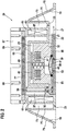
- FIG. 2 shows the functional unit 20 according to the invention.
- the functional unit 20 comprises a plurality of assemblies, such as a diaphragm pump designed as a pumping device 41, a heating element 63, a réelleleitmaschine 61, which terminates at the top with a heat conducting ring 67, a filter screen 65, a valve plate 35 and a (vent) fireplace 59th
- the functional unit 20 is inserted from below into a preferably circular opening of the storage tank 19 and then sealed by a weld 33 with the storage tank 19.
- the functional unit 20 is composed of three main components. It is a housing 21 having a cavity 23, a pump body 32 and a valve plate 35th
- the downwardly open cavity 23 is formed in the center of the housing 21, the downwardly open cavity 23 is formed.
- the pump body 32 is arranged in the cavity 23, the pump body 32 is arranged in the cavity 23, the pump body 32 is arranged.
- the cavity 23 is completed by the valve plate 35th
- a diaphragm 43 and the electromagnetic drive with an armature 45 and an electromagnet 47 are arranged in the pump body 32 .
- the diaphragm 43 is moved by the armature 45 by means of an electromagnet 47.
- the electromagnet 47 attracts the armature 45 against the spring force of a spring element 49.
- the working diaphragm 43 undergoes an up and down movement by turning on and off a current flowing through the electromagnet 47.
- reducing agent is conveyed from a working space 50 of the pumping device 41 into the delivery line 22; during the upward movement, reducing agent is sucked into the working area 50 through a suction line 51 arranged in the valve plate 35.
- valve plate 35 is in FIG. 2 integrated on the right side of the delivery line 22 for the liquid reducing agent.
- a first check valve 39 is arranged in the delivery line 22 in the delivery line 22.
- valve plate 35 is in FIG. 2 integrated on the left side of a suction line 51.
- a second check valve 53 is arranged in the suction line 51.
- the suction line 51 bends at the in FIG. 2 left end perpendicular to the top.
- the bent portion of the suction pipe 51 continues in the pump body 32 and in the pump housing 21.
- the extending in the vertical direction of the suction line in the housing 21 has the reference numeral 59 and is hereinafter referred to as a fireplace.
- the chimney 59 terminates shortly below a filter element 65.
- the filter element 65 is preferably designed as a close-meshed filter fabric and is sealingly connected at its outer edge with a heat distribution body 61.
- the suction line 51 is hydraulically connected to a first liquid reservoir 57.
- the first liquid reservoir 57 is bounded in the radial direction by a heating element 63 or a heat distribution body 61 and the cavity 23.
- FIG. 2 a liquid level of the urea-water solution is located. If the liquid level drops further than in FIG. 2 represented, then the upper end of the chimney protrudes into the air bubble located below the filter element 65.
- the diaphragm pump 41 When the diaphragm pump 41 is turned on in this state, the diaphragm pump 41 sucks through the throttle 55 the urea-water solution present in the first fluid reservoir 57. At the same time, the diaphragm pump 41 sucks air through the chimney 59. In this case, the urea-water solution and the air mix to form a two-phase mixture, which is conveyed by the diaphragm pump 41.
- the filter material is partially hydrophobic and allows little or no air through. Thus, air accumulates below the filter cloth. Some of this air was previously dissolved in the liquid or enters the system through the re-suction process to vent the system with Hilde of the 4/2 valve 99. The vacuuming takes place each time the vehicle is parked to prevent freeze damage. However, this also means that air is below filter 65 every time the vehicle is started. Without the chimney 59 and the throttle 55, the entire space 57 would fill with air over time. If the pump then sucks, reducing agent passes through the filter cloth 65 into the room 57. This would lead to uncontrolled aspiration, especially if, for example, when cornering or downhill, liquid reducing agent spills into the interior of the heat conducting ring 67.
- the heat distribution body 61 is preferably made of aluminum, although other materials can be used. In the heat distribution body 61, one or more PTC heating elements 63 are pressed. The heating elements 63 and / or the heat distribution body 61 may be coated with plastic to protect against corrosion.
- the heat-conducting body 61 goes up into a heat-conducting ring 67.
- the heat conducting body 61 and the heat conducting ring 67 support the heat transfer from the heating elements 63 to the urea-water solution.
- the casseroleleitring 67 has recesses 69, which are preferably directed sloping inwards sloping.
- the recesses 69 terminate in the interior of the heat-conducting ring 67 slightly above the filter element 65, so that the liquid reducing agent can reach the interior of the heat-conducting ring and the filter element 65, for example when driving uphill.
- the storage tank 19 forms a circumferential wall 71, which forms a further reservoir 73 with the outer wall of the heat distribution body 61.
- the second reservoir 73 has, inter alia, the function of a swirl pot.
- To the storage tank 19 is followed by the circumferential wall 71 at an inclined ramp 75, which limits the second reservoir 73.
- liquid reducing agent If liquid reducing agent is present in the storage tank, it passes through the filter element 65 into the first reservoir 57 and can be conveyed by the diaphragm pump 41 as required. This is done by 43 reducing agent is sucked from the reservoir 57 via the inlet line 51 into the work area 50 by lifting the working diaphragm 43 if necessary. By switching on the current for the electromagnet 47, the working diaphragm 43 is moved downwards via the magnet armature 45. As a result, reducing agent is conveyed through the delivery line 22 to the metering device 13.
- the reducing agent at low filling level can pass from the storage tank 19 via the ramp 75 into the second reservoir 73. From there, the reducing agent passes through the recesses 69 of the sauceleitrings 67 into the first reservoir 57. From the reservoir 57, the reducing agent is conveyed in the manner described above by the diaphragm pump 41.
- the reducing agent freezes slowly from below and outside.
- the reducing agent must be heated or thawed.
- the heating elements 63 in the cylindrical heat distribution body 61 on the other hand, the discharged heat of the electromagnet 47 can be used as a heater.
- the pumping device 41 is arranged so that the electromagnet 47 is arranged in the upper region of the functional unit 20.
- valve plate 35 closes down the functional unit 20 from plan. By this arrangement it is ensured that frost first the valve plate 35 freezes, while the area above it, in particular by the position of the heating electromagnet 47 and the heat distribution body 61 only later freezes. With such a bottom-up freezing, ice pressure can not build up because the reductant can continuously escape up to below the filter element 65.
- an air bubble 77 is present below the filter element 65, because the excreted from the reducing agent air can not escape through the close-meshed filter element 65 upwards.
- This compressible air bubble 77 absorbs the expansion of the reducing agent during the transition from the liquid phase to the solid phase and thereby prevents the functional unit 20 from being damaged by ice pressure.
- the inventive design of the functional unit 20 is characterized by a high rigidity due to the cylindrical heat distribution body 61.
- the deformation-critical pumping unit 41 and a sealing point of the valve plate 35 to the storage tank 19 are in the interior by the cylindrical heat distribution body 61 before Damage protected because the reducing agent freezes from bottom to top and the air bubble 77 absorbs the increase in volume of the freezing reducing agent.
- the peripheral wall 71 in the bottom of the storage tank makes it very soft in the radial direction, so that any deformations occurring in the wall 71 of the storage tank 19 and not take place in the functional unit 20.
Description
- Die Erfindung betrifft einen Vorratstank einer Einspritzeinrichtung nach dem Oberbegriff des Anspruchs 1 und eine Funktionseinheit hierzu.
- Aufgrund der zunehmend verschärften Abgasgesetzgebung muss insbesondere bei Kraftwagen mit Verbrennungsmotoren unter anderem der Stickoxid-Anteil im Abgas weiter reduziert werden. Eine gängige Methode ist ein Verfahren mit einem Katalysator zur selektiven katalytischen Reduktion (SCR), bei dem der gesundheitsschädliche Stickoxid-Anteil im Abgas unter zu Hilfenahme von flüssigem Reduktionsmittel, beispielsweise einer Harnstoffwasserlösung (sogenanntes AdBlue), zu Stickstoff und Wasser reduziert wird. Bei diesem Verfahren fördert in der Regel eine Pumpe das Reduktionsmittel von einem Vorratstank zu einem Dosierventil, welches das Reduktionsmittel wiederum in das Abgas einspritzt.
- Im Zusammenhang mit dem Stand der Technik und der Erfindung wird nachfolgend verschiedentlich von "oben" und "unten" gesprochen. Dabei beziehen sich diese Angaben, wenn nichts anderes gesagt wird, auf die Einbaulage des Vorratstanks.
- Aus der
WO 2010/078989 A1 ist eine elektrische Widerstands-Heizung für einen Vorratstank von flüssigem Reduktionsmittel bekannt, die im Inneren und am Boden des Vorratstanks angeordnet ist. Durch das Beheizen der wässrigen Harnstoff-Wasser-Lösung wird das Einfrieren während des Betriebs und das Auftauen des Reduktionsmittels nach einem längeren Stillstand bei Dauerfrost ermöglicht. -
EP 2 161 422 A1 beschreibt Systeme und Verfahren zur Abgabe einer Harnstofflösung an ein Abgasbehandlungssystem. Insbesondere wird ein Harnstofftank bereitgestellt. Die Harnstofftank umfasst ein Reservoir mit einer Fluideinlassöffnung zum Aufnehmen von Harnstofflösung und mit einer Fluidauslassöffnung zum Ausgeben der Harnstofflösung. Der Harnstofftank umfasst ferner ein belüftetes Hohlelement, das in dem Reservoir angeordnet ist. Das belüftete Hohlelement hat einen inneren hohlen Abschnitt und eine Vielzahl von Öffnungen, die einen Fluidfluss zwischen dem Reservoir und dem inneren hohlen Abschnitt ermöglichen. Der Harnstofftank umfasst ferner eine Heizeinrichtung, die entlang des hohlen Elements angeordnet ist, um die Harnstofflösung in dem inneren hohlen Abschnitt und in dem Reservoir zu erwärmen. Der Harnstofftank umfasst ferner eine in dem Reservoir angeordnete Fluidpumpe. Die Fluidpumpe steht in Fluidverbindung mit dem inneren hohlen Abschnitt und dem Reservoir, um die darin befindliche Harnstofflösung durch die Fluidauslassöffnung zu fördern. -
WO 2010/078989 A1 offenbart einen Vorratstank für ein Dosiersystem zum Einbringen eines Reduktionsmittels in einen Abgastrakt einer Brennkraftmaschine. Der Vorratstank weist mindestens eine Öffnung für Einbauten sowie Öffnungen zum Befüllen und Entleeren und für eine Be/Entlüftung auf, wobei sämtliche Öffnungen oberhalb eines vom Reduktionsmittels gefluteten Bereiches des Vorratstanks angeordnet sind. - Die Entnahme der flüssigen Harnstoff-Wasser-Lösung aus dem Vorratstank erfolgt bei dem aus der
WO 2010/078989 A1 bekannten System über eine Sauglanze, die über eine Öffnung an einer Tankoberseite in den Tank eingeführt wird. Bei dem aus derWO 2010/078989 A1 bekannten Vorratstank sind alle Öffnungen zum Befüllen und Entleeren des Tanks sowie die Montageöffnung zum Einbringen der Funktionseinheit oberhalb eines vom Reduktionsmittel gefluteten Bereichs des Vorratstanks angeordnet. Da jedoch die Vorratstanks verschiedener Fahrzeuge unterschiedliche Bauhöhen haben, müssen zum Beispiel die Sauglanzen, aber auch die im Inneren des Vorratstanks angeordneten Funktionseinheiten an die Tankform angepasst werden. Dies führt zwangsläufig zu einer hohen Variantenvielfalt und verursacht dadurch hohe Kosten. - Deshalb sind auch Funktionseinheiten entwickelt worden, die von unten in eine bodenseitige Öffnung im Tank eingeführt werden. Bei diesen Funktionseinheiten ist in der Regel die Pumpe oder auch ein Sensor zum Ermitteln des Füllstandes Bestandteil der Funktionseinheit. Die bekannten Ausführungen beanspruchen nachteiliger Weise jedoch einen großen Bauraum. Da der Bauraum in radialer Richtung begrenzt ist, muss die Funktionseinheit in die Höhe gebaut werden. Damit ragt die Funktionseinheit, insbesondere das Filter, bis etwa in die Mitte des Vorratstanks und ist deshalb stark eisdruckgefährdet. Das Reduktionsmittel gefriert nämlich stets von einer Außenseite des Tanks zum Innern, das heißt, dass nach einer längeren Gefrierphase in der Mitte des Tanks eine Flüssigkeitsblase übrig bleibt, die dann schlagartig einfrieren kann und sich dabei um ca. 10% ausdehnt. Dadurch entsteht ein erheblicher Druck, der sogenannte Eisdruck, leicht zu Schäden an den mit Eisdruck beaufschlagten Bauteilen der Funktionseinheit führen.
- Die vorliegende Erfindung unterscheidet sich von dem eingangsgenannten Stand der Technik dadurch, dass zwischen der Öffnung einer Saugleitung (22) im Vorratstank und einem im Wesentlichen vertikal angeordneten Kamin ein als Drossel wirkender Spalt vorhanden ist.
- Die Kombination eines Kamins, dessen oberes Ende in der Regel in eine unterhalb eines Filterelements befindliche Luftblase ragt, und eines Spalts, über den flüssiges Reduktionsmittel angesaugt wird, führt dazu, dass auch bei teilweise mit Luft beziehungsweise Abgas gefüllter Saugleitung, rasch und zuverlässig zumindest ein Zwei-Phasen-Gemisch aus Reduktionsmittel und Luft von der Pumpeneinheit gefördert wird. Dadurch wird ein zuverlässiger Betrieb des Dosiersystems erreicht und insbesondere Fehlermeldungen beziehungsweise Instabilitäten der Regelung des Dosiersystems verhindert. Im Ergebnis werden dadurch auch die Schadstoffemissionen reduziert.
- Weitere vorteilhafte Ausgestaltungen der Erfindung sehen vor, dass die Funktionseinheit ein Gehäuse, einen Pumpenkörper und eine Ventilplatte umfasst, und dass die Funktionseinheit in eine Öffnung im Boden des Vorratstanks eingesetzt und dichtend mit dem Vorratstank verbunden ist. In der Ventilplatte sind eine Saugleitung und eine Förderleitung ausgebildet sind. Des weiteren können die Heizeinrichtung und eventuelle Sensoren auch noch in die Funktionseinheit integriert werden, so dass die erfindungsgemäße Funktionseinheit baut kompakt und vor allem sehr flach. Es sind darüber hinaus vorteilhafterweise keine Leitungen zur Oberseite des Vorratstanks nötig.
- In einer bevorzugten Ausführungsform wird das Gehäuse der Funktionseinheit von unten in den Vorratstank eingesetzt und wird mit dem Vorratstank verschweißt. Dies gewährleistet eine einfache Montage und die nötige Dichtigkeit des Vorratstanks.
- Weiterhin ist vorteilhaft, dass die Funktionseinheit zum Fördern des Reduktionsmittels durch die Förderleitung eine Pumpeinrichtung aufweist, die einen Elektromagneten, eine Arbeitsmembrane und die Ventilplatte umfasst. Die Arbeitsmembrane ist bevorzugt im Bereich der Ventilplatte bzw. eines Einlasses der Förderleitung angeordnet; der Elektromagnet ist bevorzugt in einem der Ventilplatte entgegengesetzten Bereich der Funktionseinheit angeordnet. An der Membrane ist ein Anker angeordnet, der durch ein Ein- und Ausschalten eines Stromes durch des Elektromagneten bewegt werden kann. Die Pumpeinrichtung kann daher vorteilhafterweise im Gegensatz zu den bekannten Vorrichtungen relativ flach aufgebaut werden. Durch ein so mögliches Auf- und Abschwingen der Arbeitsmembrane wird durch so erzeugte Pumpbewegungen der Arbeitsmembrane der Zufluss bzw. der Abfluss von Reduktionsmitteln in die Funktionseinheit bzw. aus der Funktionseinheit gesteuert. In der Zufluss- und Förderleitung angeordnete Ventilelemente unterstützen die jeweilige Funktion des Zuflusses und des Abflusses in die bzw. aus der Funktionseinheit. Ein in der Funktionseinrichtung angeordneter Entlüftungskanal kann für die nötige Entlüftung, insbesondere im Bereich des Zuflusses, sorgen.
- Besonders vorteilhaft ist, dass die Funktionseinheit durch mindestens eine Heizvorrichtung beheizbar ist. Heizvorrichtungen sind in der Funktionseinheit nötig, damit bei Frost das Reduktionsmittel flüssig gehalten werden kann, bzw. nach einem Einfrieren im Stillstand des Fahrzeugs wieder aufgetaut werden kann. Die Heizvorrichtung kann dabei PTC Heizelemente umfassen, wobei die Heizelemente vorzugsweise in einen zylinderförmigen Aluminiumkörper eingepresst sind. Der Aluminiumkörper kann zur Vermeidung von Korrosion nachträglich mit Kunststoff umspritzt sein und stellt einen Wärmeverteilkörper dar. Andere gut wärmeleitende Materialien alternativ zu Aluminium sind natürlich auch möglich. Der zylinderförmige Wärmeverteilkörper kann dabei so breit ausgelegt sein, dass er im Wesentlichen alle Komponenten der Funktionseinheit umschließt, um die Komponenten der Funktionseinheit bei Bedarf zu beheizen bzw. aufzutauen. Der zylinderförmige Aluminiumkörper zeichnet sich durch eine hohe Steifigkeit aus, so dass besonders die im Innern des zylinderförmigen Aluminiumkörpers angeordnete druckempfindliche Komponenten der Funktionseinheit, wie die Pumpeinrichtung und die Abdichtungsbereiche der Ventilplatte zum Vorratstank, bei einem Eisdruck bei Frost ausreichend geschützt sind.
- Da der Elektromagnet eher im oberen Bereich der Funktionseinheit angeordnet ist, ist die beim Bestromen des Elektromagnets erzeugte Wärme für Einrichtungen der Funktionseinheit nutzbar, die insbesondere im oberen Bereich der Funktionseinheit, wie z.B. ein Filterelement, angeordnet sind. Der Elektromagnet stellt damit neben dem Wärmeverteilkörper eine zweite Heizvorrichtung innerhalb der Funktionseinheit dar.
- Weiterhin ist vorteilhaft, dass die Funktionseinheit zum Filtern des in den Vorratstank eingeführten Reduktionsmittels ein Filterelement, bevorzugt ein Filtergewebe aufweist, das mittelbar beheizbar ist. Das Filtergewebe ist dabei bevorzugt so feinmaschig ausgebildet, dass Partikel des Reduktionsmittels heraus gefiltert werden können, damit sie die Zuflussleitung bzw. die Förderleitung nicht verstopfen können. Sinnvollerweise ist das Filtergewebe im oberen Teil der Funktionseinheit angeordnet, dass es im Wesentlichen die Funktionseinheit bedeckt und dass das Filtergewebe durch den in diesem Bereich angeordneten Elektromagneten beheizbar ist. Auch die Heizelemente im zylinderförmigen Wärmeverteilkörper können Wärme in den Bereich des Filtergewebes leiten, damit dieses bei Bedarf beheizt werden kann. Bei einer Erwartung von besonders viel herauszufilternden Partikeln, kann das Filtergewebe auch wellig über der Funktionseinheit angeordnet sein, so dass eine Filteroberfläche wesentlich vergrößert werden kann. Möglich ist auch, dass das Filtergewebe tauschbar fixiert werden kann.
- Damit insbesondere die Wärme aus den Heizelementen des bevorzugt kunststoffummantelten, zylinderförmigen Wärmeverteilkörpers in möglichst viele Bereiche der Funktionseinheit gelangen kann, ist es vorteilhaft, dass die Funktionseinheit an einer der Ventilplatte gegenüberliegenden Seite einen Wärmeleitring aufweist. Der Wärmeleitring gewährleistet, dass die Wärme beispielsweise an darüber liegendes Eis des Vorratstanks bestmöglich geleitet werden kann. Der Kunststoff der Ummantelung kann den Wärmeübergang unterstützen, Der Wärmeleitring sorgt für einen optimalen Übergang der Wärme an das Eis beim Auftauen. Darüber hinaus kann der Wärmeleitring an einer zu einem Vorratstankdeckel zeigenden Seite Aussparungen aufweisen, die beim Fahren des Kraftfahrzeugs im Vorratstank schwappendes, flüssiges Reduktionsmittel einfangen können. Die Aussparungen ermöglichen so, dass auch bei einem niedrigen Füllstand des Reduktionsmittels die Funktionseinheit genügend Reduktionsmittel im Innern zum Fördern aufweisen kann.
- Damit immer genügend Reduktionsmittel in der Funktionseinheit zum Fördern vorhanden ist, ist es vorteilhaft, dass die Funktionseinheit mindestens ein Reservoir für Reduktionsmittel umfasst. Ein erstes Reservoir kann dabei bevorzugt im Innern des beheizbaren zylinderförmigen Wärmeverteilkörpers liegen. Dadurch wird sichergestellt, dass auch bei Frost das Reduktionsmittel beheizbar und flüssiges Reduktionsmittel im Reservoir vorhanden ist, damit es durch die Funktionseinheit gefördert werden kann.
- Ferner ist vorteilhaft, dass direkt von außen an die Funktionseinheit angrenzend ein zweites Reservoir für Reduktionsmittel vorgesehen ist. Dieses außerhalb der eigentlichen Funktionseinheit angeordnete zweite Reservoir kann derart im Vorratstank angeordnet sein, dass es ebenfalls durch den zylinderförmigen Wärmeverteilkörper beheizt werden kann. Durch bspw. eine im Vorratstank außerhalb der Funktionseinheit an das weitere Reservoir angrenzende schräg in Richtung des weiteren Reservoirs verlaufende Rampe, ist es möglich, dass das weitere Reservoir auch bei relativ niedrigen Füllstand des Vorratstanks ständig durch Schwappbewegungen mit Reduktionsmittel gefüllt wird. Durch Schwappbewegungen während des Fahrens kann das Reduktionsmittel des weiteren Reservoirs anschließend über die Aussparungen des Wärmeleitrings ins Innere der Funktionseinheit gelangen.
- Weitere Merkmale und Vorteile der Erfindung ergeben sich aus den abhängigen Ansprüchen, der Beschreibung und den beigefügten Figuren. Es versteht sich, dass die vorstehend genannten und die nachstehend noch zu erläuternden Merkmale nicht nur in der jeweils angegebenen Kombination, sondern auch in anderen Kombinationen oder in Alleinstellung einen wesentlichen Aspekt der Erfindung darstellen können. Die Figuren zeigen ein bevorzugtes Ausführungsbeispiel der Erfindung und werden in der nachfolgenden Beschreibung näher erläutert. Dabei zeigen:
- Fig. 1
- das Umfeld der Erfindung; und
- Fig. 2
- eine erfindungsgemäße Funktionseinheit eines Vorratstanks.
- In
Figur 1 ist eine Brennkraftmaschine 1 mit einer Abgasnachbehandlungseinrichtung 3 stark vereinfacht und schematisch dargestellt und zeigt das Umfeld der Erfindung. Die Abgasnachbehandlungseinrichtung 3 umfasst ein Abgasrohr 5, einen Oxidationskatalysator 7 und einen SCR-Katalysator 11 zur selektiven katalytischen Reduktion von gesundheitsschädlichem Stickoxid. Nicht dargestellt ist ein Partikelfilter, der üblicherweise stromabwärts des Oxidationskatalysators 7 angeordnet ist. Die Strömungsrichtung des Abgases durch das Abgasrohr 5 ist durch Pfeile (ohne Bezugszeichen) angedeutet. - Um den SCR-Katalysator 11 mit einem flüssigen Reduktionsmittel, z.B. einer Harnstoff-Wasser-Lösung (sog. AdBlue) oder einem anderen flüssigen Reduktionsmittel zu versorgen, ist stromaufwärts des SCR-Katalysators 11 am Abgasrohr 5 eine Dosiereinrichtung 13 für die Harnstoff-Wasser-Lösung angeordnet. Die Dosiereinrichtung 13 spritzt bei Bedarf die Harnstoff-Wasser-Lösung stromaufwärts des SCR-Katalysators 11 in das Abgasrohr 5 ein.
- Ein Dosiersystem zum gezielten Einspritzen der Harnstoff-Wasser-Lösung umfasst neben der Dosiereinrichtung 13 einen Vorratstank 19, in dem eine erfindungsgemäße Funktionseinheit 20 zum Fördern flüssigen Reduktionsmittels integriert ist.
- Mit dem Bezugszeichen 99 ist ein 4/2-Wegeventil dargestellt, welches dazu dient, die Förderrichtung der Funktionseinheit 20 umzukehren. Dadurch ist es möglich, das Dosiersystem weitestgehend zu entleeren, so dass Schäden bei gefrierendem Reduktionsmittel vermieden werden können.
- Die Funktionseinheit 20 umfasst eine Pumpeinrichtung 41 (siehe
Figur 2 ), die bevorzugt elektrisch betätigt werden kann. Zwischen dem Vorratstank 19 und der Dosiereinrichtung 13 ist eine Förderleitung 22 vorgesehen. Sie ist bevorzugt am Vorratstank 19 unten angeschlossen. Die Förderleitung 22 kann zumindest teilweise als Schlauch ausgebildet sein. Die Funktionseinheit 20 kann einen Sensor zur Ermittlung eines Füllstandes im Vorratstank 19 umfassen (nicht dargestellt). - Der Vollständigkeit halber sei noch auf in der Abgasanlage angeordnete Sensoren, nämlich einen Stickoxid-Sensor 25, sowie Temperatur-Sensoren 24 und 27 hingewiesen. Diese Sensoren 24, 25 und 27 sind über Signalleitungen (ohne Bezugszeichen) mit einem ersten Steuergerät 29 der Brennkraftmaschine 1 verbunden. Das erste Steuergerät 29 steuert die Brennkraftmaschine 1 und sendet und empfängt Daten von einem zweiten Steuergerät 31 des Dosiersystems für die Harnstoff-Wasser-Lösung. Die Signalverbindungen von und zum zweiten Steuergerät 31 des Dosiersystems sind in
Figur 1 durch gestrichelte Linien dargestellt. -
Figur 2 zeigt die erfindungsgemäße Funktionseinheit 20. Die Funktionseinheit 20 umfasst eine Vielzahl von Baugruppen, wie zum Beispiel eine als Membranpumpe ausgebildete Pumpeinrichtung 41, ein Heizelement 63, einen Wärmeleitkörper 61, der oben mit einem Wärmeleitring 67 abschließt, ein Filtersieb 65, eine Ventilplatte 35 und einen (Entlüftungs-)Kamin 59. - Die Funktionseinheit 20 wird von unten in eine bevorzugt kreisrunde Öffnung des Vorratstanks 19 eingesetzt und anschließend durch eine Schweißnaht 33 dichtend mit dem Vorratstank 19 verbunden.
- Die Funktionseinheit 20 setzt sich aus drei Hauptbestandteilen zusammen. Es sind die ein Gehäuse 21 mit einer Kavität 23, ein Pumpenkörper 32 und eine Ventilplatte 35.
- Im Zentrum des Gehäuses 21 ist die nach unten offene Kavität 23 ausgebildet. In der Kavität 23 ist der Pumpenkörper 32 angeordnet. Abgeschlossen wird die Kavität 23 von der Ventilplatte 35.
- In dem Pumpenkörper 32 sind einem Arbeitsraum 50, eine Membran 43 und deren elektromagnetischen Antrieb mit einem Anker 45 und einem Elektromagnet 47 angeordnet. Die Membrane 43 wird durch den Magnetanker 45 mit Hilfe eines Elektromagneten 47 bewegt. Im Betrieb zieht der Elektromagnet 47 den Magnetanker 45 gegen die Federkraft eines Federelements 49 an. Im Betrieb erfährt die Arbeitsmembrane 43 durch Ein- und Ausschalten eines durch den Elektromagneten 47 durchfließenden Stroms eine Auf- und Abwärtsbewegung. Bei der Abwärtsbewegung wird Reduktionsmittel aus einem Arbeitsraum 50 der Pumpeinrichtung 41 in die Förderleitung 22 gefördert, bei der Aufwärtsbewegung wird Reduktionsmittel durch eine in der Ventilplatte 35 angeordnete Saugleitung 51 in den Arbeitsbereich 50 angesaugt.
- In der Ventilplatte 35 ist in
Figur 2 auf der rechten Seite die Förderleitung 22 für das flüssige Reduktionsmittel integriert. In der Förderleitung 22 ist ein erstes Rückschlagventil 39 angeordnet. - In der Ventilplatte 35 ist in
Figur 2 auf der linken Seite eine Saugleitung 51 integriert. In der Saugleitung 51 ist ein zweites Rückschlagventil 53 angeordnet. Die Saugleitung 51 knickt an dem inFigur 2 linken Ende senkrecht nach oben ab. Der abgeknickte Teil der Saugleitung 51 setzt sich in dem Pumpenkörper 32 und in dem Pumpengehäuse 21 fort. - Die in vertikaler Richtung verlaufende Verlängerung der Saugleitung in dem Gehäuse 21 hat das Bezugszeichen 59 und wird nachfolgend als Kamin bezeichnet. Der Kamin 59 endet kurz unterhalb eines Filterelements 65. Das Filterelement 65 ist bevorzugt als ein engmaschiges Filtergewebe ausgeführt und ist an seinem äußeren Rand dichtend mit einem Wärmeverteilkörper 61 verbunden.
- Zwischen dem unteren Ende das Kamins 59 und dem vertikalen Abschnitt der Saugleitung 51 ist ein als Drossel 55 wirkender Spalt vorhanden. Über den Spalt 55 ist die Saugleitung 51 hydraulisch mit einem ersten Flüssigkeits-Reservoir 57 verbunden. Das erste Flüssigkeits-Reservoir 57 wird in radialer Richtung von einem Heizelement 63 beziehungsweise einem Wärmeverteilkörper 61 und der Kavität 23 begrenzt.
- In der
Figur 2 ist ein Flüssigkeitsspiegel der Harnstoff-Wasser-Lösung eingezeichnet. Wenn der Flüssigkeitsspiegel weiter absinkt als inFigur 2 dargestellt, dann ragt das obere Ende des Kamins in die unterhalb des Filterelements 65 befindliche Luftblase. - Wenn in diesem Zustand die Membranpumpe 41 eingeschaltet wird, dann saugt die Membranpumpe 41 durch die Drossel 55 die in dem ersten Flüssigkeits-Reservoir 57 vorhandenen Harnstoff-Wasser-Lösung an. Gleichzeitig saugt die Membranpumpe 41 durch den Kamin 59 Luft an. Dabei vermischen sich die Harnstoff-Wasser-Lösung und die Luft zu einem Zwei-Phasen-Gemisch, das von der Membranpumpe 41 gefördert wird.
- Das Filtermaterial ist teilweise hydrophob und lässt nur wenig oder gar keine Luft durch. Somit sammelt sich unterhalb des Filtergewebes Luft an. Diese Luft war zum Teil zuvor in der Flüssigkeit gelöst oder kommt durch den Rücksaugvorgang zum Entlüften des Systems mit Hilde des über 4/2-Ventils 99 in das System. Das Rücksaugen erfolgt bei jedem Abstellen des Fahrzeugs, um Schäden durch Einfrieren zu verhindern. Dies bedeutet aber auch, dass bei jedem Start des Fahrzeugs Luft unterhalb des Filters 65 ist. Ohne den Kamin 59 und die Drossel 55 würde sich im Laufe der Zeit der gesamte Raum 57 mit Luft füllen. Saugt dann die Pumpe, so gelangt Reduktionsmittel durch das Filtergewebe 65 in den Raum 57. Dies würde zu einem unkontrollierten Absaugen führen, vor allem wenn zum Beispiel bei einer Kurvenfahrt oder einer Bergabfahrt flüssiges Reduktionsmittel in das Innere des Wärmeleitrings 67 schwappt.
- Der Wärmeverteilkörper 61 ist bevorzugt aus Aluminium hergestellt, wobei auch andere Materialien eingesetzt werden können. In den Wärmeverteilkörper 61 sind ein oder mehrere PTC-Heizelemente 63 eingepresst. Die Heizelemente 63 und/oder oder der Wärmeverteilkörper 61 können zum Schutz vor Korrosion mit Kunststoff beschichtet sein.
- Der Wärmeleitkörper 61 geht nach oben in einen Wärmeleitring 67 über. Der Wärmeleitkörper 61 und der Wärmeleitring 67 unterstützen die Wärmeübertragung von den Heizelementen 63 auf die Harnstoff-wasser-Lösung.
- Der Wärmeleitring 67 weist Aussparungen 69 auf, die bevorzugt schräg nach innen abfallend gerichtet sind. Die Aussparungen 69 enden im Innern des Wärmeleitrings 67 etwas oberhalb des Filterelements 65, so dass das flüssige Reduktionsmittel zum Beispiel bei einer Bergauffahrt in das Innere des Wärmeleitrings und auf das Filterelement 65 gelangen kann.
- Außerhalb des zylindrischen Wärmeverteilkörpers 61 bildet der Vorratstank 19 eine umlaufende Wand 71, die mit der Außenwandung des Wärmeverteilkörpers 61 ein weiteres Reservoir 73 bildet. Das zweite Reservoir 73 hat unter anderem die Funktion eines Schwalltopfs. Zum Vorratstank 19 schließt sich an die umlaufende Wand 71 eine schräg verlaufende Rampe 75 an, welche das zweite Reservoir 73 begrenzt.
- Wenn in dem Vorratstank flüssiges Reduktionsmittel vorhanden ist, gelangt es durch das Filterelement 65 in das erste Reservoir 57 und kann bei Bedarf von der Membranpumpe 41 gefördert werden. Dies geschieht indem bei Bedarf durch Anheben der Arbeitsmembrane 43 Reduktionsmittel aus dem Reservoir 57 über die Zuflussleitung 51 in den Arbeitsbereich 50 gesaugt wird. Durch Einschalten des Stroms für den Elektromagneten 47 wird über den Magnetanker 45 die Arbeitsmembrane 43 abwärts bewegt. Dadurch wird Reduktionsmittel durch die Förderleitung 22 zur Dosiereinrichtung 13 gefördert.
- Durch Schwappbewegungen des Reduktionsmittels während einer Fahrt kann das Reduktionsmittel bei niedrigem Füllstand aus dem Vorratstank 19 über die Rampe 75 in das zweite Reservoir 73 gelangen. Von dort gelangt das Reduktionsmittel über die Aussparungen 69 des Wärmeleitrings 67 in das erste Reservoir 57. Aus dem Reservoir 57 wird das Reduktionsmittel in der oben beschriebenen Weise von der Membranpumpe 41 gefördert.
- Wenn strenger Frost herrscht, friert das Reduktionsmittel langsam von unten und außen ein. Um flüssiges Reduktionsmittel bereitstellen zu können, muss das Reduktionsmittel beheizt bzw. aufgetaut werden. Hierzu dienen einerseits die Heizelemente 63 im zylinderförmigen Wärmeverteilkörper 61, andererseits kann die abgegebene Wärme des Elektromagneten 47 als Heizvorrichtung genutzt werden. Zweckmäßigerweise ist die Pumpeinrichtung 41 so angeordnet, dass der Elektromagnet 47 im oberen Bereich der Funktionseinheit 20 angeordnet ist.
- Die Ventilplatte 35 schließt nach unten die Funktionseinheit 20 plan ab. Durch diese Anordnung ist gewährleistet, dass bei Frost zunächst die Ventilplatte 35 einfriert, während der darüber liegende Bereich, insbesondere durch die Lage des wärmenden Elektromagneten 47 und des Wärmeverteilkörpers 61 erst später einfriert. Bei einem solchen von unten nach oben gerichteten Einfrieren, kann sich kein Eisdruck aufbauen, da das Reduktionsmittel kontinuierlich nach oben bis unter das Filterelement 65 entweichen kann.
- Unterhalb des Filterelements 65 ist eine Luftblase 77 vorhanden, weil die aus dem Reduktionsmittel ausgeschiedene Luft nicht durch das engmaschige Filterelement 65 nach oben entweichen kann. Diese kompressible Luftblase 77 nimmt die Ausdehnung des Reduktionsmittels beim Übergang von der flüssigen Phase zur festen Phase auf und verhindert dadurch, dass die Funktionseinheit 20 durch Eisdruck beschädigt wird.
- Infolge der Volumenzunahme des gefrierenden Reduktionsmittels kann es im Vorratstank 19 zu erheblichen Verformungen kommen. Das erfindungsgemäße Design der Funktionseinheit 20 zeichnet sich aufgrund des zylinderförmigen Wärmeverteilkörpers 61 durch eine hohe Steifigkeit aus. Die verformungskritische Pumpeinheit 41 sowie eine Dichtstelle der Ventilplatte 35 zum Vorratstank 19 sind im Innern durch den zylinderförmigen Wärmeverteilkörpers 61 vor Beschädigungen geschützt, weil das Reduktionsmittel von unten nach oben durchfriert und die Luftblase 77 die Volumenzunahme des gefrierenden Reduktionsmittels aufnimmt.
- Die umlaufende Wand 71 im Boden des Vorratstanks macht diesen in radialer Richtung sehr weich, so dass eventuell auftretende Verformungen in der Wand 71 des Vorratstanks 19 und nicht in der Funktionseinheit 20 stattfinden.
Claims (12)
- Funktionseinheit (20) für einen Vorratstank (19) für ein flüssiges Reduktionsmittel, wobei die Funktionseinheit (20) im Boden des Vorratstanks (19) vorsehbar ist, mit einer Pumpeinrichtung (41), die dazu eingerichtet ist, das Reduktionsmittel aus dem Vorratstank (19) zu fördern, dadurch gekennzeichnet, dass zwischen einer Öffnung, die in einem vertikalen Abschnitt einer Saugleitung (51) ausgebildet ist, und einem unteren Ende eines im Wesentlichen vertikal angeordneten Kamins (59) ein als Drossel wirkender Spalt (55) vorhanden ist, wobei die Saugleitung über den Spalt (55) hydraulisch mit einem ersten Reservoir (57) für Reduktionsmittel verbunden ist, und wobei der Kamin (59) kurz unterhalb eines Filterelements (65) endet und eingerichtet ist zum Ansaugen von Luft, welche sich unterhalb des Filterelements (65) ansammeln kann.
- Funktionseinheit (20) nach Anspruch 1, dadurch gekennzeichnet, dass sie in eine Öffnung im Boden des Vorratstanks (19) einsetzbar und dichtend mit dem Vorratstank (19) verbindbar ist.
- Funktionseinheit (20) nach Anspruch 1 oder 2, dadurch gekennzeichnet, dass sie mindestens ein Gehäuse (21), einen Pumpenkörper (32) und eine Ventilplatte (35) umfasst.
- Funktionseinheit (20) nach Anspruch 3, dadurch gekennzeichnet, dass in der Ventilplatte (35) eine Saugleitung (51) und eine Förderleitung (22) ausgebildet sind.
- Funktionseinheit (20) nach einem der vorhergehenden Ansprüche, dadurch gekennzeichnet, dass die Pumpeinrichtung (41) einen Anker (45), einen Elektromagneten (47), eine Membran (43) und eine beziehungsweise die Ventilplatte (35) umfasst.
- Funktionseinheit (20) nach einem der vorhergehenden Ansprüche, dadurch gekennzeichnet, dass sie durch ein Heizelement (63), einen Wärmeleitkörper (61) und/oder einen Wärmeleitring (67) beheizbar ist.
- Funktionseinheit (20) nach Anspruch 6, dadurch gekennzeichnet, dass der Wärmeleitkörper (61) und/oder der Wärmeleitring (67) im Wesentlichen zylinderförmig ausgebildet ist.
- Funktionseinheit (20) nach einem der vorhergehenden Ansprüche, dadurch gekennzeichnet, dass am oberen Ende des Wärmeleitkörpers (61) das als Filtergewebe ausgeführte Filterelement (65) dichtend angebracht ist.
- Funktionseinheit (20) nach einem der Ansprüche 6 bis 8, dadurch gekennzeichnet, dass der Wärmeleitring (67) Aussparungen (69) aufweist, die beim Fahren im Vorratstank (19) schwappende Flüssigkeit einfangen.
- Funktionseinheit (20) nach einem der Ansprüche 6 bis 9, dadurch gekennzeichnet, dass der Wärmeleitkörper (61) das erste Reservoir (57) für Reduktionsmittel begrenzt.
- Funktionseinheit (20) nach einem der vorhergehenden Ansprüche, dadurch gekennzeichnet, dass sich im Betrieb unterhalb des Filterelements (65) eine Luftblase (77) bildet.
- Vorratstank (19) für ein flüssiges Reduktionsmittel, wobei im Boden des Vorratstanks (19) eine Funktionseinheit (20) nach einem der vorangehenden Ansprüche vorgesehen ist.
Applications Claiming Priority (2)
| Application Number | Priority Date | Filing Date | Title |
|---|---|---|---|
| DE102011075726A DE102011075726A1 (de) | 2011-05-12 | 2011-05-12 | Vorratstank und Funktionseinheit hierzu |
| PCT/EP2012/055314 WO2012152498A1 (de) | 2011-05-12 | 2012-03-26 | Vorratstank und funktionseinheit hierzu |
Publications (2)
| Publication Number | Publication Date |
|---|---|
| EP2707579A1 EP2707579A1 (de) | 2014-03-19 |
| EP2707579B1 true EP2707579B1 (de) | 2018-07-04 |
Family
ID=45928878
Family Applications (1)
| Application Number | Title | Priority Date | Filing Date |
|---|---|---|---|
| EP12711852.9A Not-in-force EP2707579B1 (de) | 2011-05-12 | 2012-03-26 | Vorratstank und funktionseinheit hierzu |
Country Status (4)
| Country | Link |
|---|---|
| EP (1) | EP2707579B1 (de) |
| CN (1) | CN103518046B (de) |
| DE (1) | DE102011075726A1 (de) |
| WO (1) | WO2012152498A1 (de) |
Families Citing this family (11)
| Publication number | Priority date | Publication date | Assignee | Title |
|---|---|---|---|---|
| DE102012204402B4 (de) | 2012-03-20 | 2020-01-02 | Robert Bosch Gmbh | Elektronisches Schaltungsmodul zur Steuerung einer Hubmagnetmembranpumpe und Verfahren zum Betreiben der Hubmagnetmembranpumpe |
| DE102013101573A1 (de) * | 2013-02-18 | 2014-08-21 | Emitec France S.A.S | Verfahren zum Beheizen einer Fördervorrichtung |
| DE102013108501A1 (de) | 2013-08-07 | 2015-03-05 | Emitec Gesellschaft Für Emissionstechnologie Mbh | Verfahren zur Herstellung eines Fördermoduls zum Einbau in einen Tank |
| US9957862B2 (en) | 2014-04-03 | 2018-05-01 | Robert Bosch Gmbh | Secondary heating device for diesel exhaust fluid tank |
| DE102014222743A1 (de) * | 2014-11-06 | 2016-05-12 | Continental Automotive Gmbh | Pumpeneinheit für Reduktionsmittel einer Abgasreinigungsanlage |
| DE102015206589A1 (de) * | 2015-04-14 | 2016-10-20 | Continental Automotive Gmbh | Verfahren zum Bestimmen einer Temperatur einer Membran einer Pumpe |
| US10634033B2 (en) | 2015-12-10 | 2020-04-28 | Continental Automotive Gmbh | Tank system for a reducing agent |
| EP3428438A1 (de) * | 2017-07-13 | 2019-01-16 | Kautex Textron GmbH & Co. Kg | Flüssigkeitsbehälter mit heizvorrichtung |
| DE102017222301A1 (de) * | 2017-12-08 | 2019-06-13 | Continental Automotive Gmbh | SCR-Dosiereinheit zur Förderung und Bereitstellung eines flüssigen Abgasreinigungsadditivs |
| DE102018117181A1 (de) * | 2018-07-16 | 2020-01-16 | Kautex Textron Gmbh & Co. Kg | Flüssigkeitsbehälter für ein Kraftfahrzeug und Verfahren zum Herstellen eines Flüssigkeitsbehälters für ein Kraftfahrzeug |
| FR3096738B1 (fr) * | 2019-05-31 | 2021-05-28 | Plastic Omnium Advanced Innovation & Res | Dispositif de fixation pour module de distribution de solution aqueuse contenue dans un réservoir à bord d’un véhicule automobile |
Family Cites Families (7)
| Publication number | Priority date | Publication date | Assignee | Title |
|---|---|---|---|---|
| DE102005037201A1 (de) * | 2005-08-06 | 2007-02-22 | Eichenauer Heizelemente Gmbh & Co. Kg | Heizsystem |
| US20100050606A1 (en) * | 2008-09-04 | 2010-03-04 | Fulks Gary C | Urea tank assembly |
| DE102009000101A1 (de) * | 2009-01-09 | 2010-07-15 | Robert Bosch Gmbh | Tankgestaltung |
| DE102010004614A1 (de) * | 2010-01-13 | 2011-07-14 | Emitec Gesellschaft für Emissionstechnologie mbH, 53797 | Tankanordnung und Dosiersystem für ein Reduktionsmittel |
| CN201666176U (zh) * | 2010-03-05 | 2010-12-08 | 苏州派格力减排系统有限公司 | 柴油车用储液罐加压式尿素溶液计量喷射系统 |
| DE102010003310A1 (de) * | 2010-03-26 | 2011-09-29 | Robert Bosch Gmbh | Vorrichtung zur Vermeidung des Flutens eines Förder- oder Dosiersystems |
| DE102010029636A1 (de) * | 2010-06-02 | 2011-12-08 | Robert Bosch Gmbh | Vorratsbehälter für Flüssigkeiten mit einem Flüssigkeitssumpf für ein Kraftfahrzeug |
-
2011
- 2011-05-12 DE DE102011075726A patent/DE102011075726A1/de not_active Withdrawn
-
2012
- 2012-03-26 CN CN201280022686.3A patent/CN103518046B/zh not_active Expired - Fee Related
- 2012-03-26 EP EP12711852.9A patent/EP2707579B1/de not_active Not-in-force
- 2012-03-26 WO PCT/EP2012/055314 patent/WO2012152498A1/de active Application Filing
Non-Patent Citations (1)
| Title |
|---|
| None * |
Also Published As
| Publication number | Publication date |
|---|---|
| EP2707579A1 (de) | 2014-03-19 |
| WO2012152498A1 (de) | 2012-11-15 |
| CN103518046A (zh) | 2014-01-15 |
| CN103518046B (zh) | 2016-06-29 |
| DE102011075726A1 (de) | 2012-11-15 |
Similar Documents
| Publication | Publication Date | Title |
|---|---|---|
| EP2707579B1 (de) | Vorratstank und funktionseinheit hierzu | |
| EP2453115B1 (de) | Flüssigkeitsbehälter, insbesondere für eine wässrige Harnstofflösung | |
| EP1925354B1 (de) | Katalytische Reduktionseinrichtung | |
| EP2094953B1 (de) | Vorrichtung zum dosieren eines flüssigen reduktionsmittels | |
| EP2569522B1 (de) | Vorrichtung zur reduktion von schadstoffen im abgasstrom eines verbrennungsmotors | |
| EP2157295B1 (de) | Dosiersystem für ein flüssiges Medium, insbesondere Harnstoff-Wasser-Lösung | |
| DE102005002318A1 (de) | Abgasnachbehandlungsverfahren und Vorrichtung hierzu | |
| WO2009121644A1 (de) | Vorrichtung zum dosieren eines flüssigen reduktionsmittels | |
| DE102006061734A1 (de) | Vorrichtung zum Dosieren eines Reduktionsmittels | |
| DE102013210742A1 (de) | Tankvorrichtung | |
| EP2288795B1 (de) | Scr-system mit mehreren tanks | |
| WO2010046152A1 (de) | Dosiersystem für ein flüssiges medium, insbesondere harnstoff-wasser-lösung | |
| EP3325782B1 (de) | Einspritzventil eines abgasnachbehandlungssystems | |
| DE102007033470B4 (de) | Vorrichtung und Verfahren zur Dosierung eines Reduktionsmittels in einen Abgastrakt eines Fahrzeugs | |
| DE102009011018A1 (de) | Vorrichtung zum Zuführen eines Hilfsmittels zu einer Abgasnachbehandlungseinrichtung eines Kraftfahrzeugs | |
| DE102009054735A1 (de) | Verfahren zum Betreiben eines SCR-Katalysatorsystems | |
| WO2016142107A1 (de) | Behälter für ein flüssiges betriebsmittel eines kraftfahrzeuges und kraftfahrzeug mit einem solchen behälter | |
| EP2577010B1 (de) | Fluidspeichereinrichtung | |
| WO2018121908A1 (de) | Tankvorrichtung für ein fahrzeug | |
| DE102010039115A1 (de) | Vorratstank für flüssiges Reduktionsmittel | |
| DE102021102696A1 (de) | Behälter für ein flüssiges Betriebsmittel eines Kraftfahrzeuges und Kraftfahrzeug mit einem solchen Behälter | |
| WO2020038640A1 (de) | Tankanordnung | |
| EP2450541A1 (de) | Tankanordnung | |
| WO2018103923A1 (de) | Reduktionsmittel-einspritzvorrichtung | |
| DE102016224237A1 (de) | Reduktionsmittel-Einspritzvorrichtung |
Legal Events
| Date | Code | Title | Description |
|---|---|---|---|
| PUAI | Public reference made under article 153(3) epc to a published international application that has entered the european phase |
Free format text: ORIGINAL CODE: 0009012 |
|
| 17P | Request for examination filed |
Effective date: 20131212 |
|
| AK | Designated contracting states |
Kind code of ref document: A1 Designated state(s): AL AT BE BG CH CY CZ DE DK EE ES FI FR GB GR HR HU IE IS IT LI LT LU LV MC MK MT NL NO PL PT RO RS SE SI SK SM TR |
|
| DAX | Request for extension of the european patent (deleted) | ||
| STAA | Information on the status of an ep patent application or granted ep patent |
Free format text: STATUS: EXAMINATION IS IN PROGRESS |
|
| 17Q | First examination report despatched |
Effective date: 20171114 |
|
| GRAP | Despatch of communication of intention to grant a patent |
Free format text: ORIGINAL CODE: EPIDOSNIGR1 |
|
| STAA | Information on the status of an ep patent application or granted ep patent |
Free format text: STATUS: GRANT OF PATENT IS INTENDED |
|
| INTG | Intention to grant announced |
Effective date: 20180404 |
|
| GRAS | Grant fee paid |
Free format text: ORIGINAL CODE: EPIDOSNIGR3 |
|
| GRAA | (expected) grant |
Free format text: ORIGINAL CODE: 0009210 |
|
| STAA | Information on the status of an ep patent application or granted ep patent |
Free format text: STATUS: THE PATENT HAS BEEN GRANTED |
|
| AK | Designated contracting states |
Kind code of ref document: B1 Designated state(s): AL AT BE BG CH CY CZ DE DK EE ES FI FR GB GR HR HU IE IS IT LI LT LU LV MC MK MT NL NO PL PT RO RS SE SI SK SM TR |
|
| REG | Reference to a national code |
Ref country code: GB Ref legal event code: FG4D Free format text: NOT ENGLISH |
|
| REG | Reference to a national code |
Ref country code: CH Ref legal event code: EP |
|
| REG | Reference to a national code |
Ref country code: AT Ref legal event code: REF Ref document number: 1014744 Country of ref document: AT Kind code of ref document: T Effective date: 20180715 |
|
| REG | Reference to a national code |
Ref country code: IE Ref legal event code: FG4D Free format text: LANGUAGE OF EP DOCUMENT: GERMAN |
|
| REG | Reference to a national code |
Ref country code: DE Ref legal event code: R096 Ref document number: 502012012979 Country of ref document: DE |
|
| REG | Reference to a national code |
Ref country code: NL Ref legal event code: MP Effective date: 20180704 |
|
| REG | Reference to a national code |
Ref country code: LT Ref legal event code: MG4D |
|
| PG25 | Lapsed in a contracting state [announced via postgrant information from national office to epo] |
Ref country code: NL Free format text: LAPSE BECAUSE OF FAILURE TO SUBMIT A TRANSLATION OF THE DESCRIPTION OR TO PAY THE FEE WITHIN THE PRESCRIBED TIME-LIMIT Effective date: 20180704 |
|
| PG25 | Lapsed in a contracting state [announced via postgrant information from national office to epo] |
Ref country code: CZ Free format text: LAPSE BECAUSE OF FAILURE TO SUBMIT A TRANSLATION OF THE DESCRIPTION OR TO PAY THE FEE WITHIN THE PRESCRIBED TIME-LIMIT Effective date: 20180704 Ref country code: PL Free format text: LAPSE BECAUSE OF FAILURE TO SUBMIT A TRANSLATION OF THE DESCRIPTION OR TO PAY THE FEE WITHIN THE PRESCRIBED TIME-LIMIT Effective date: 20180704 Ref country code: LT Free format text: LAPSE BECAUSE OF FAILURE TO SUBMIT A TRANSLATION OF THE DESCRIPTION OR TO PAY THE FEE WITHIN THE PRESCRIBED TIME-LIMIT Effective date: 20180704 Ref country code: BG Free format text: LAPSE BECAUSE OF FAILURE TO SUBMIT A TRANSLATION OF THE DESCRIPTION OR TO PAY THE FEE WITHIN THE PRESCRIBED TIME-LIMIT Effective date: 20181004 Ref country code: SE Free format text: LAPSE BECAUSE OF FAILURE TO SUBMIT A TRANSLATION OF THE DESCRIPTION OR TO PAY THE FEE WITHIN THE PRESCRIBED TIME-LIMIT Effective date: 20180704 Ref country code: IS Free format text: LAPSE BECAUSE OF FAILURE TO SUBMIT A TRANSLATION OF THE DESCRIPTION OR TO PAY THE FEE WITHIN THE PRESCRIBED TIME-LIMIT Effective date: 20181104 Ref country code: NO Free format text: LAPSE BECAUSE OF FAILURE TO SUBMIT A TRANSLATION OF THE DESCRIPTION OR TO PAY THE FEE WITHIN THE PRESCRIBED TIME-LIMIT Effective date: 20181004 Ref country code: FI Free format text: LAPSE BECAUSE OF FAILURE TO SUBMIT A TRANSLATION OF THE DESCRIPTION OR TO PAY THE FEE WITHIN THE PRESCRIBED TIME-LIMIT Effective date: 20180704 Ref country code: GR Free format text: LAPSE BECAUSE OF FAILURE TO SUBMIT A TRANSLATION OF THE DESCRIPTION OR TO PAY THE FEE WITHIN THE PRESCRIBED TIME-LIMIT Effective date: 20181005 Ref country code: RS Free format text: LAPSE BECAUSE OF FAILURE TO SUBMIT A TRANSLATION OF THE DESCRIPTION OR TO PAY THE FEE WITHIN THE PRESCRIBED TIME-LIMIT Effective date: 20180704 |
|
| PG25 | Lapsed in a contracting state [announced via postgrant information from national office to epo] |
Ref country code: LV Free format text: LAPSE BECAUSE OF FAILURE TO SUBMIT A TRANSLATION OF THE DESCRIPTION OR TO PAY THE FEE WITHIN THE PRESCRIBED TIME-LIMIT Effective date: 20180704 Ref country code: ES Free format text: LAPSE BECAUSE OF FAILURE TO SUBMIT A TRANSLATION OF THE DESCRIPTION OR TO PAY THE FEE WITHIN THE PRESCRIBED TIME-LIMIT Effective date: 20180704 Ref country code: HR Free format text: LAPSE BECAUSE OF FAILURE TO SUBMIT A TRANSLATION OF THE DESCRIPTION OR TO PAY THE FEE WITHIN THE PRESCRIBED TIME-LIMIT Effective date: 20180704 Ref country code: AL Free format text: LAPSE BECAUSE OF FAILURE TO SUBMIT A TRANSLATION OF THE DESCRIPTION OR TO PAY THE FEE WITHIN THE PRESCRIBED TIME-LIMIT Effective date: 20180704 |
|
| REG | Reference to a national code |
Ref country code: DE Ref legal event code: R097 Ref document number: 502012012979 Country of ref document: DE |
|
| PG25 | Lapsed in a contracting state [announced via postgrant information from national office to epo] |
Ref country code: EE Free format text: LAPSE BECAUSE OF FAILURE TO SUBMIT A TRANSLATION OF THE DESCRIPTION OR TO PAY THE FEE WITHIN THE PRESCRIBED TIME-LIMIT Effective date: 20180704 Ref country code: IT Free format text: LAPSE BECAUSE OF FAILURE TO SUBMIT A TRANSLATION OF THE DESCRIPTION OR TO PAY THE FEE WITHIN THE PRESCRIBED TIME-LIMIT Effective date: 20180704 Ref country code: RO Free format text: LAPSE BECAUSE OF FAILURE TO SUBMIT A TRANSLATION OF THE DESCRIPTION OR TO PAY THE FEE WITHIN THE PRESCRIBED TIME-LIMIT Effective date: 20180704 |
|
| PLBE | No opposition filed within time limit |
Free format text: ORIGINAL CODE: 0009261 |
|
| STAA | Information on the status of an ep patent application or granted ep patent |
Free format text: STATUS: NO OPPOSITION FILED WITHIN TIME LIMIT |
|
| PG25 | Lapsed in a contracting state [announced via postgrant information from national office to epo] |
Ref country code: SK Free format text: LAPSE BECAUSE OF FAILURE TO SUBMIT A TRANSLATION OF THE DESCRIPTION OR TO PAY THE FEE WITHIN THE PRESCRIBED TIME-LIMIT Effective date: 20180704 Ref country code: SM Free format text: LAPSE BECAUSE OF FAILURE TO SUBMIT A TRANSLATION OF THE DESCRIPTION OR TO PAY THE FEE WITHIN THE PRESCRIBED TIME-LIMIT Effective date: 20180704 Ref country code: DK Free format text: LAPSE BECAUSE OF FAILURE TO SUBMIT A TRANSLATION OF THE DESCRIPTION OR TO PAY THE FEE WITHIN THE PRESCRIBED TIME-LIMIT Effective date: 20180704 |
|
| 26N | No opposition filed |
Effective date: 20190405 |
|
| PG25 | Lapsed in a contracting state [announced via postgrant information from national office to epo] |
Ref country code: SI Free format text: LAPSE BECAUSE OF FAILURE TO SUBMIT A TRANSLATION OF THE DESCRIPTION OR TO PAY THE FEE WITHIN THE PRESCRIBED TIME-LIMIT Effective date: 20180704 |
|
| PG25 | Lapsed in a contracting state [announced via postgrant information from national office to epo] |
Ref country code: MC Free format text: LAPSE BECAUSE OF FAILURE TO SUBMIT A TRANSLATION OF THE DESCRIPTION OR TO PAY THE FEE WITHIN THE PRESCRIBED TIME-LIMIT Effective date: 20180704 |
|
| REG | Reference to a national code |
Ref country code: CH Ref legal event code: PL |
|
| GBPC | Gb: european patent ceased through non-payment of renewal fee |
Effective date: 20190326 |
|
| PG25 | Lapsed in a contracting state [announced via postgrant information from national office to epo] |
Ref country code: LU Free format text: LAPSE BECAUSE OF NON-PAYMENT OF DUE FEES Effective date: 20190326 |
|
| REG | Reference to a national code |
Ref country code: BE Ref legal event code: MM Effective date: 20190331 |
|
| PG25 | Lapsed in a contracting state [announced via postgrant information from national office to epo] |
Ref country code: LI Free format text: LAPSE BECAUSE OF NON-PAYMENT OF DUE FEES Effective date: 20190331 Ref country code: CH Free format text: LAPSE BECAUSE OF NON-PAYMENT OF DUE FEES Effective date: 20190331 Ref country code: GB Free format text: LAPSE BECAUSE OF NON-PAYMENT OF DUE FEES Effective date: 20190326 Ref country code: IE Free format text: LAPSE BECAUSE OF NON-PAYMENT OF DUE FEES Effective date: 20190326 |
|
| PG25 | Lapsed in a contracting state [announced via postgrant information from national office to epo] |
Ref country code: BE Free format text: LAPSE BECAUSE OF NON-PAYMENT OF DUE FEES Effective date: 20190331 |
|
| PG25 | Lapsed in a contracting state [announced via postgrant information from national office to epo] |
Ref country code: TR Free format text: LAPSE BECAUSE OF FAILURE TO SUBMIT A TRANSLATION OF THE DESCRIPTION OR TO PAY THE FEE WITHIN THE PRESCRIBED TIME-LIMIT Effective date: 20180704 |
|
| PG25 | Lapsed in a contracting state [announced via postgrant information from national office to epo] |
Ref country code: PT Free format text: LAPSE BECAUSE OF FAILURE TO SUBMIT A TRANSLATION OF THE DESCRIPTION OR TO PAY THE FEE WITHIN THE PRESCRIBED TIME-LIMIT Effective date: 20181105 Ref country code: MT Free format text: LAPSE BECAUSE OF FAILURE TO SUBMIT A TRANSLATION OF THE DESCRIPTION OR TO PAY THE FEE WITHIN THE PRESCRIBED TIME-LIMIT Effective date: 20180704 |
|
| PGFP | Annual fee paid to national office [announced via postgrant information from national office to epo] |
Ref country code: FR Payment date: 20200325 Year of fee payment: 9 |
|
| PGFP | Annual fee paid to national office [announced via postgrant information from national office to epo] |
Ref country code: DE Payment date: 20200526 Year of fee payment: 9 |
|
| REG | Reference to a national code |
Ref country code: AT Ref legal event code: MM01 Ref document number: 1014744 Country of ref document: AT Kind code of ref document: T Effective date: 20190326 |
|
| PG25 | Lapsed in a contracting state [announced via postgrant information from national office to epo] |
Ref country code: AT Free format text: LAPSE BECAUSE OF NON-PAYMENT OF DUE FEES Effective date: 20190326 |
|
| PG25 | Lapsed in a contracting state [announced via postgrant information from national office to epo] |
Ref country code: CY Free format text: LAPSE BECAUSE OF FAILURE TO SUBMIT A TRANSLATION OF THE DESCRIPTION OR TO PAY THE FEE WITHIN THE PRESCRIBED TIME-LIMIT Effective date: 20180704 |
|
| PG25 | Lapsed in a contracting state [announced via postgrant information from national office to epo] |
Ref country code: HU Free format text: LAPSE BECAUSE OF FAILURE TO SUBMIT A TRANSLATION OF THE DESCRIPTION OR TO PAY THE FEE WITHIN THE PRESCRIBED TIME-LIMIT; INVALID AB INITIO Effective date: 20120326 |
|
| REG | Reference to a national code |
Ref country code: DE Ref legal event code: R119 Ref document number: 502012012979 Country of ref document: DE |
|
| PG25 | Lapsed in a contracting state [announced via postgrant information from national office to epo] |
Ref country code: DE Free format text: LAPSE BECAUSE OF NON-PAYMENT OF DUE FEES Effective date: 20211001 Ref country code: FR Free format text: LAPSE BECAUSE OF NON-PAYMENT OF DUE FEES Effective date: 20210331 |
|
| PG25 | Lapsed in a contracting state [announced via postgrant information from national office to epo] |
Ref country code: MK Free format text: LAPSE BECAUSE OF FAILURE TO SUBMIT A TRANSLATION OF THE DESCRIPTION OR TO PAY THE FEE WITHIN THE PRESCRIBED TIME-LIMIT Effective date: 20180704 |