EP2452736B1 - Gruppierung von schwingungsvorrichtungen für filterplatten eines pressfilters - Google Patents
Gruppierung von schwingungsvorrichtungen für filterplatten eines pressfilters Download PDFInfo
- Publication number
- EP2452736B1 EP2452736B1 EP10796648.3A EP10796648A EP2452736B1 EP 2452736 B1 EP2452736 B1 EP 2452736B1 EP 10796648 A EP10796648 A EP 10796648A EP 2452736 B1 EP2452736 B1 EP 2452736B1
- Authority
- EP
- European Patent Office
- Prior art keywords
- sleeve
- filter
- disposed
- spring
- hole
- Prior art date
- Legal status (The legal status is an assumption and is not a legal conclusion. Google has not performed a legal analysis and makes no representation as to the accuracy of the status listed.)
- Active
Links
Images



Classifications
-
- B—PERFORMING OPERATIONS; TRANSPORTING
- B01—PHYSICAL OR CHEMICAL PROCESSES OR APPARATUS IN GENERAL
- B01D—SEPARATION
- B01D25/00—Filters formed by clamping together several filtering elements or parts of such elements
- B01D25/32—Removal of the filter cakes
- B01D25/322—Removal of the filter cakes specially for chamber filter presses
-
- B—PERFORMING OPERATIONS; TRANSPORTING
- B01—PHYSICAL OR CHEMICAL PROCESSES OR APPARATUS IN GENERAL
- B01D—SEPARATION
- B01D25/00—Filters formed by clamping together several filtering elements or parts of such elements
- B01D25/12—Filter presses, i.e. of the plate or plate and frame type
- B01D25/164—Chamber-plate presses, i.e. the sides of the filtering elements being clamped between two successive filtering plates
-
- B—PERFORMING OPERATIONS; TRANSPORTING
- B01—PHYSICAL OR CHEMICAL PROCESSES OR APPARATUS IN GENERAL
- B01D—SEPARATION
- B01D25/00—Filters formed by clamping together several filtering elements or parts of such elements
- B01D25/12—Filter presses, i.e. of the plate or plate and frame type
-
- B—PERFORMING OPERATIONS; TRANSPORTING
- B01—PHYSICAL OR CHEMICAL PROCESSES OR APPARATUS IN GENERAL
- B01D—SEPARATION
- B01D25/00—Filters formed by clamping together several filtering elements or parts of such elements
- B01D25/12—Filter presses, i.e. of the plate or plate and frame type
- B01D25/172—Plate spreading means
-
- B—PERFORMING OPERATIONS; TRANSPORTING
- B01—PHYSICAL OR CHEMICAL PROCESSES OR APPARATUS IN GENERAL
- B01D—SEPARATION
- B01D25/00—Filters formed by clamping together several filtering elements or parts of such elements
- B01D25/32—Removal of the filter cakes
-
- B—PERFORMING OPERATIONS; TRANSPORTING
- B01—PHYSICAL OR CHEMICAL PROCESSES OR APPARATUS IN GENERAL
- B01D—SEPARATION
- B01D25/00—Filters formed by clamping together several filtering elements or parts of such elements
- B01D25/32—Removal of the filter cakes
- B01D25/34—Removal of the filter cakes by moving, e.g. rotating, the filter elements
- B01D25/346—Removal of the filter cakes by moving, e.g. rotating, the filter elements by vibration
Definitions
- the invention relates to the technical category of a shaking device for a filter press, and more particularly to a shaking device for filter plates of a filter press, which is used to separate filter plates in batches to remove filter cakes.
- Filter presses are regarded as the main filtration equipment in the solid-liquid separation industry. To complete a filter cycle, liquid-solid slurries are first filtered to leave the filter cakes in the filter chambers formed by the filter plates, and then the automatic shifting device operates to separate the filter plates to remove the filter cakes.
- a filter press has a large filtration area and a plurality of filter plates, and thus it takes a long time to separate the filter plates individually.
- a method for removal of the filter cakes has been developed by separating the filter plates in batches.
- CN 1012933153 recites a press filter comprising a movable frame which is movable along the horizontal beam of the press filter (along the direction in which the filter plates align in parallel).
- the movable frame comprises a washing mechanism for cleaning the filter clothes controlled by a PLC program, having a motor, a rotatable disk driven by the motor, a transmission belt mounted on the rotatable disk, and a horizontal lead-out pipe made from stainless steel which is connected to the transmission belt and which leads out water to wash away micro-particles remaining on the filter cloth.
- the process of cleaning a filter cloth in CN 1012933153 is fulfilled by moving the movable frame to aim at a specific filter plate, then driving the rotatable disk to rotate by the motor and correspondingly, rolling up the transmission belt to lift the horizontal lead-out pipe to a suitable position, and then turning on water to wash the filter cloth.
- US 5,846,415 recites a press filter comprising a pair of horizontal guide rails in the body frame, a plurality of filter plates each movably mounted on the guide rails and each having vertical surfaces parallel to each other, a plurality of support bars perpendicularly disposed above the guide rails each parallel to a vertical surface of the filter plates and each is elastically connected a filter plate, a plurality of filter clothes each disposed on one filter plate by wrapping the upper portion of the filter cloth around the support bar which is disposed above the filter plate, a vibration rod attached to the lower surfaces of the support rods, and a lifting mechanism for vibrating vertically the vibration rod.
- the vibration rod may be attached to several support rods such that when the vibration rod is vibrated, the several filter plates (or clothes) are shaken to remove filter cakes remaining thereon at the same time.
- GB 2046117 recites a filter cake removing apparatus, comprising a pair of guide rails extending between the front and rear frames, a gate girder mounted on the guide rails for back and forth movement, and a means for providing vibration for cake removal disposed on the gate girder.
- the means for providing vibration in GB 2046117 pushes the lower surfaces of the gate girder or pushes the upper surfaces of the gate girder to vibrate the filter plate.
- a highly-efficient and energy-saving shaking device of a filter press movable along the rows of the filter plates to clean the different batches of the filter plates was known in the art.
- a shaking device for filter plates of a filter press comprises a fixed support and a movable frame, the fixed support comprising a main beam and a support crossbeam, wherein the shaking device further comprises a sleeve spring device; one end of the sleeve spring device is attached to the frame crossbeam and the other end is attached to a shaking rod;
- the movable frame comprises a frame crossbeam and a vertical beam;
- the movable frame is disposed on the support crossbeam;
- the movable frame is driven by a gear motor comprising a gear box, and the gear box of the gear motor is disposed with a symmetrical drive shaft;
- a limiting device is disposed on the movable frame to control the move thereof;
- one side of the main beam of the fixed support is provided with a chain stand, on which a chain is disposed; on the chain is disposed with a main air pipe, and one end of the main air pipe is connected with an air supply joint and the other end is connected with an
- One end of the drive shaft is disposed with a pulley and a gear for the operation of the movable frame, and the gear fits with a gear rack that is located on the upper end surface of the main beam.
- the sleeve spring device comprises a sleeve body, a sleeve spring, and a sleeve shaft; the lower end of the sleeve body is fixed with a sleeve base plate and the sleeve base plate is fixedly connected with the shaking rod; the lower end
- the upper end of the sleeve shaft is fixed on the lower base plate of a sleeve hanger plate and the sleeve hanger plate is connected with the frame crossbeam.
- the cylinder assembly is disposed under the frame crossbeam.
- the three-way air connector is disposed on the vertical beam of the movable frame.
- the pulley is disposed on the upper end of the movable frame, and a movable wheel is disposed on the lower end of the frame crossbeam.
- the shaking device for filter plates of a filter press provided by the invention is disposed on the upper end of the press filter and the shaking device is controlled by a PLC (Programmable Logic Controller) program.
- PLC Programmable Logic Controller
- the moveable frame moves to the shaking position via the gear driven by the gear motor and then stops automatically by electrically controlled proximity switches that are disposed on the filter plates.
- the air diverting valve opens to allow the cylinder to act on the shaking rod via the three-way air connector and the times of shaking is controlled.
- the shaking rod automatically retracts from the sleeve spring device.
- the filter cakes on the filter cloth drop off automatically while the filter cloth rods are shaken by the shaking rod.
- the second group of the filter plates are separated after the first shaking is completed.
- the electrically controlled limiting device disposed at the end of the filter press functions to allow the movable frame to move back to its original position.
- Such a process comprising the shaking times and moving route is controlled by a PLC program. It is simple, accurate, rapid, and convenient.
- the shaking device for filter plates provided by the invention has a simple structure and is easy to be operated, and meanwhile the filter cakes can be effectively removed and the filter cloth can keep sufficient air permeability.
- the whole process is fully controlled automatically.
- the problem that the filter cakes fail to drop off automatically after the filter plates are separated has been solved, the desired effects are achieved, and the production efficiency is improved.
- manual removal work is not required during the whole process, therefore labor intensity is reduced, and the filter cloth is unlikely to be damaged. It not only saves the costs but achieves excellent filtration effects.
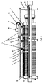
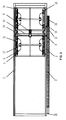
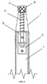
- Main beam 1 gear rack 2, filter cloth 3, filter plate 4, sleeve spring device 5, cylinder assembly 6, wheel 7, gear 8, gear motor 9, front support leg 10, shaking rod 11, pulley 12, three-way air connector 13, drive shaft 14, vertical beam 15, movable frame crossbeam 16, chain 17, thrust plate 18, air diverting valve 19, main air pipe 20, air subpipe 21, air supply joint 22, support leg 23, support crossbeam 24, spring support 25, filter cloth spring 26, filter cloth rod 27, spring shaft 28, cover of filter cloth rod 29, sleeve body 30, sleeve shaft 31, sleeve hanger plate 32, sleeve base plate 33, sleeve spring 34, flange 35, nut 36, rear support leg 37, oil cylinder seat 38.
- a shaking device for filter plates of a filter press comprises a fixed support, a movable frame, and a sleeve spring device 5.
- the fixed support comprises a main beam 1 and a support crossbeam 24.
- the main beam 1 and the support crossbeam 24 are made of Q235 (Q235 represents an ordinary carbon steel with a yield value of about 235 MPa) welded rectangular tubes.
- Q235 represents an ordinary carbon steel with a yield value of about 235 MPa
- One end of the sleeve spring device is attached to a frame crossbeam 16 of the movable frame and the other end is attached to a shaking rod 11.
- On the support crossbeam 24 is disposed with the movable frame.
- the movable frame comprises the frame crossbeam 16 and a vertical beam 15, which are made of Q235 welded channel steels.
- a limiting device is disposed on the movable frame.
- the movable frame is driven by a gear motor 9, which is disposed on the vertical beam 15 of the movable frame.
- a gear box of the gear motor is disposed with a symmetrical drive shaft 14.
- the drive shaft 14 is located in a bore of the gear motor 9 and the other end of the drive shaft 14 is disposed with a pulley 12 and a gear 8 for the operation of the movable frame.
- the gear fits with a gear rack 2 that is arranged on the upper end surface of the main beam 1.
- the pulley 12 is disposed on the upper end of the movable frame.
- On the lower end of the frame crossbeam 16 is disposed with a movable wheel 7, which are used for positioning when the movable frame is in back-and-forth movement.
- the wheel 7 is provided with a wheel carrier.
- the chain serves as a support for an air pipe, which is disposed on the chain and moves with the movable frame.
- the air diverting valve 19 comprises a welded base support that is connected with the frame crossbeam 16.
- the air diverting valve 19 is connected with a cylinder assembly 6 and a three-way air connector 13 in turn via an air subpipe 21.
- the three-way air connector 13 is disposed on the vertical beam 15 of the movable frame and the cylinder assembly 6 is disposed under the frame crossbeam.
- the fixed support is disposed on the upper end of the filter press via support legs.
- a front support leg 10 is attached to a thrust plate 18 of the filter press and a rear support leg 37 is attached to an oil cylinder seat 38.
- the sleeve spring device 5 comprises a sleeve body 30, a sleeve spring 34, and a sleeve shaft 31.
- a sleeve body 30 At the lower end of the sleeve body 30 is fixed with a sleeve base plate 33 and the sleeve base plate 33 is welded on the shaking rod 11.
- the lower end of the sleeve shaft 31 is disposed with a flange 35 that is attached to the sleeve spring 34 and the other end of the flange 35 is attached to the shaking rod 11.
- the upper end of the sleeve shaft 31 is fixed on the lower base plate of a sleeve hanger plate 32.
- the upper end of the sleeve shaft 31 is disposed with a screw thread and a flange 35, which are fastened on the lower base plate of the sleeve hanger plate 32 via a nut 36.
- the sleeve hanger plate 32 is connected with the frame crossbeam 16 via a bolt.
- the shaking rod is connected with the sleeve spring. When the cylinder piston rod acts on the shaking rod, the shaking rod shakes to separate and shakes a plurality of filter cloth rods 27 of the filter plates to remove the filter cakes.
- the filter plate 4 is disposed on the main beam of the filter press.
- a spring support 25 of the filter cloth is disposed at both sides of the upper end of the filter plate 4.
- the central portion of a spring shaft 28 of the filter cloth is disposed with a filter cloth spring 26 attached to the spring support 25 of the filter cloth.
- the lower end of the spring shaft 28 of the filter cloth is disposed with a screw thread and a nut to attach to the spring support 25 of the filter cloth.
- the upper end of the spring shaft 28 is disposed with a square cover 29 of the filter cloth rods having two holes.
- the filter cloth rods 27 are disposed in the holes of the square cover 29 with two ends fixed by circlips.
- the filter cloth 3 is fixed on the filter cloth rods 27 in a shape of a sleeve.
- the central feed port of the filter cloth 3 is fastened in the feed port of the filter plate 4 by filter cloth clamps.
- the shaking device for filter plates of a filter press provided by the invention is disposed on the upper end of the filter press and the shaking device is controlled by a PLC program.
Landscapes
- Chemical & Material Sciences (AREA)
- Chemical Kinetics & Catalysis (AREA)
- Filtration Of Liquid (AREA)
- Cleaning In General (AREA)
Claims (2)
- Schüttelvorrichtung für Filterplatten einer Filterpresse, umfassend:einen festen Träger, wobei der feste Träger ein Paar Hauptträger (1) umfasst;ein Paar Zahnstangen (2), die sich jeweils auf der oberen Fläche des Hauptträgers (1) befinden;einen beweglichen Rahmen, wobei der beweglichen Rahmen ein Paar Rahmenquerträger (16) und einen Träger (15) umfasst, der zwischen den Rahmenquerträgern (16) und senkrecht zu diesen verbunden ist;einen Zahnradmotor (9), umfassend eine Antriebswelle (14), die auf dem Träger (15) angeordnet ist, wobei jedes Ende der Antriebswelle (14) mit einem Antriebsritzel (8) und einer Rolle (12) verbunden ist;einen Kettenständer, in dem eine Kette (17) enthalten ist, die auf einer Seite von einem der Hauptträger (1) angeordnet ist;ein Hauptluftrohr (20), das auf der Kette (17) angeordnet ist;ein Luftumleitungsventil (19), umfassend einen Basisträger, der auf einen der Rahmenquerträger (16) geschweißt ist, wobei das Luftumleitungsventil (19) über das Hauptluftrohr (20) mit einem Luftzufuhranschluss (21) verbunden ist;ein Nebenluftrohr (21);einen Drei-Wege-Anschluss (13), der auf dem Träger (15) angeordnet ist;eine Zylindereinheit (6);die Filtertuchstäbe (27), von denen jeder eine Filterplatte trägt;einen Schüttelstab (11), der über den Filtertuchstäben (27) angeordnet ist und über die Filtertuchstäbe (27) verläuft; undeine Federhülsenvorrichtung (5), umfassend einen Hülsenkörper (30), der eine Hülsenbasisplatte (33) aufweist, einen Hülsenschaft (31), eine Hülsenaufhängeplatte (32), eine Federhülse (34), einen ersten Flansch (35), einen zweiten Flansch (35) und eine Gewindemutter (36);wobei:das Antriebsritzel (8) mit einer Zahnstange (2) zusammenpasst und die Rolle (12) am oberen Ende des Rahmenquerträgers (16) angeordnet ist und die obere Fläche des Hauptträgers (1) berührt, wobei sich, wenn der Zahnradmotor (9) das Antriebsritzel (8) und die Rolle (12) über die Antriebswelle (14) bewegt, der bewegliche Rahmen glatt entlang der Hauptträger (1) bewegt; unddas Luftumleitungsventil (19) mit dem Drei-Wege-Anschluss (13) und der Zylindereinheit (6) abwechselnd über das Luftnebenrohr (21) verbunden ist;dadurch gekennzeichnet, dass:der Schüttelstab (11) über die Federhülsenvorrichtung (5) mit dem Rahmenquerträger (16) verbunden ist;die Zylindereinheit (6) an der unteren Fläche des Rahmenquerträgers (16) fixiert und direkt über dem Schüttelstab (11) angeordnet ist;in der Hülsenbasisplatte (33) ein erstes Loch angeordnet ist und im Schüttelstab (11) ein zweites Loch angeordnet ist, und die Hülsenbasisplatte (33) derart auf den Schüttelstab (11) geschweißt ist, dass das erste Loch und das zweite Loch zusammenfallen;in dem oberen Ende des Hülsenkörpers (30) ein drittes Loch angeordnet ist und das dritte Loch in einer Linie mit dem ersten Loch und dem zweiten Loch ausgerichtet ist;der Hülsenschaft (31) das erste Loch, das zweite Loch und das dritte Loch beweglich passiert;das untere Ende des Hülsenschaftes (31) das erste Loch und das zweie Loch über den ersten Flansch (35) passiert;die Federhülse (34) auf dem Hülsenschaft (31) angeordnet ist, ein Ende der Federhülse (34) an dem oberen Ende des Hülsenkörpers (30) angebracht ist und das andere Ende an dem ersten Flansch (35) angebracht ist;das obere Ende des Hülsenschaftes (31) über den zweiten Flansch (35) und die Gewindemutter (36) am unteren Ende der Hülsenaufhängeplatte (32) befestigt ist,das obere Ende der Hülsenaufhängeplatte (32) über einen Bolzen an der unteren Fläche des Rahmenquerträgers (16) befestigt ist; undbeim Reinigen einer Charge von Filtertüchern der bewegliche Rahmen derart die Hauptträger (1) entlang bewegt wird, dass der Schüttelstab (11) über die Charge von Filtertüchern läuft; dann wird das Luftumleitungsventil (19) geöffnet, um die Zylindereinheit (6) anzutreiben, auf den Schüttelstab (11) einzuwirken, wodurch der Schüttelstab (11) auf die Filtertuchstangen schlägt, um die Charge von Filtertüchern zu schütteln; und schließlich der Schüttelstab (11) nach dem Schütteln der Charge von Filtertüchern durch die Federkraft der Federhülse (34) zurückgezogen wird.
- Vorrichtung nach Anspruch 1, ferner umfassend:ein Paar Federaufhängungen (25), die jeweils auf einer Schulter einer Filterplatte angeordnet sind;einen Federschaft (28); undeine Filtertuchfeder (26), die auf dem Federschaft (28) angeordnet ist;wobei:das untere Ende des Federschaftes (28) mit der Federaufhängung (25) verbunden ist und das obere Ende des Federschaftes (28) mit dem Filtertuchstab (27) verbunden ist;ein Ende der Filtertuchfeder (26) die obere Fläche der Federaufhängung (25) berührt und das andere Ende die untere Fläche des Filtertuchstabs (27) berührt; undwenn der Filtertuchstab (27) von dem Schüttelstab (11) getroffen wird, aufgrund der Federkräfte der Filtertuchfeder (26) durch die Filtertuchfeder (26) eine schüttelnde Kraft auf die Filterplatte wirksam ausgeübt wird.
Applications Claiming Priority (2)
| Application Number | Priority Date | Filing Date | Title |
|---|---|---|---|
| CN2009101583336A CN101601942B (zh) | 2009-07-07 | 2009-07-07 | 压滤机滤板分组振打装置 |
| PCT/CN2010/000819 WO2011003271A1 (zh) | 2009-07-07 | 2010-06-10 | 压滤机滤板分组振打装置 |
Publications (3)
| Publication Number | Publication Date |
|---|---|
| EP2452736A1 EP2452736A1 (de) | 2012-05-16 |
| EP2452736A4 EP2452736A4 (de) | 2013-01-02 |
| EP2452736B1 true EP2452736B1 (de) | 2014-02-19 |
Family
ID=41467925
Family Applications (1)
| Application Number | Title | Priority Date | Filing Date |
|---|---|---|---|
| EP10796648.3A Active EP2452736B1 (de) | 2009-07-07 | 2010-06-10 | Gruppierung von schwingungsvorrichtungen für filterplatten eines pressfilters |
Country Status (6)
| Country | Link |
|---|---|
| US (1) | US8206582B2 (de) |
| EP (1) | EP2452736B1 (de) |
| KR (1) | KR101598652B1 (de) |
| CN (1) | CN101601942B (de) |
| RU (1) | RU2526386C2 (de) |
| WO (1) | WO2011003271A1 (de) |
Families Citing this family (30)
| Publication number | Priority date | Publication date | Assignee | Title |
|---|---|---|---|---|
| CN101601942B (zh) | 2009-07-07 | 2011-04-13 | 景津压滤机集团有限公司 | 压滤机滤板分组振打装置 |
| WO2015127366A2 (en) * | 2014-02-21 | 2015-08-27 | Flsmidth A/S | Filter press for high performance liquid/solid separations and methods thereof |
| CN104028019B (zh) * | 2014-07-01 | 2016-05-25 | 谢宇强 | 油过滤器 |
| CN104941274A (zh) * | 2015-05-29 | 2015-09-30 | 景津环保股份有限公司 | 一种板框式压滤机污泥处理工艺管道系统 |
| CN105031989B (zh) * | 2015-08-21 | 2017-03-29 | 核工业烟台同兴实业有限公司 | 一种卧式压滤机振打卸料装置 |
| US9833741B2 (en) * | 2015-08-24 | 2017-12-05 | Doosan Heavy Industries & Constructions Co., Ltd. | Submerged membrane filtration system using reciprocating membrane |
| CN105214353B (zh) * | 2015-11-06 | 2017-03-01 | 唐伟 | 一种用于易燃易爆滤液进行板框压滤的密闭式压滤机 |
| CN105749648A (zh) * | 2016-04-05 | 2016-07-13 | 张海娟 | 自排式除尘装置 |
| CN105749649B (zh) * | 2016-04-21 | 2017-09-15 | 安徽工业大学 | 一种连续清灰再生过滤式除尘器 |
| CN107930202A (zh) * | 2017-12-29 | 2018-04-20 | 天津远新环保科技有限公司 | 一种振动卸料的板框式泥浆压滤机 |
| AT521195B1 (de) * | 2018-04-27 | 2023-01-15 | Andritz Tech & Asset Man Gmbh | Filterpresse sowie Verfahren zum Betreiben einer Filterpresse |
| KR101983101B1 (ko) * | 2018-06-08 | 2019-09-03 | 경규혁 | 여과포 진동 또는 회전 장치가 구비된 필터 프레스 시스템 |
| JP7033248B2 (ja) * | 2018-11-05 | 2022-03-10 | 株式会社石垣 | フィルタープレスのろ布洗浄方法 |
| CN111939641A (zh) * | 2020-08-08 | 2020-11-17 | 孙治国 | 一种钕铁硼废料回收用溶解液的挤压过滤装置 |
| CN112044129A (zh) * | 2020-09-15 | 2020-12-08 | 景津环保股份有限公司 | 自动振布脱饼装置及相应自动脱饼压滤机 |
| CN112156513B (zh) * | 2020-09-18 | 2022-04-05 | 昆山市天丰印刷包装有限公司 | 一种压滤机清洁装置 |
| CN112477235B (zh) * | 2020-10-16 | 2022-01-18 | 地宝集团有限公司 | 一种多种类生物基因提取装置 |
| CN112370811A (zh) * | 2020-10-26 | 2021-02-19 | 佛山市南海区锐翔科技有限公司 | 一种用于水玻璃生产线的产品高效回收系统 |
| CN112426759B (zh) * | 2020-11-30 | 2023-04-07 | 中国航发动力股份有限公司 | 一种电解液自动压滤机及其工作方法 |
| CN113521825B (zh) * | 2020-12-18 | 2022-06-28 | 第一环保(深圳)股份有限公司 | 压滤机滤布电机振动脱渣机构 |
| CN112892012B (zh) * | 2021-04-15 | 2024-07-23 | 景津装备股份有限公司 | 自动振布脱饼挂车及相应自动振布与洗布兼容式压滤机 |
| KR102321862B1 (ko) * | 2021-05-27 | 2021-11-04 | (주)선진인더스트리 | 필터프레스 여과판의 슬러지케이크 자동 탈리장치 |
| CN114344964B (zh) * | 2021-12-02 | 2023-07-28 | 兴源环境科技股份有限公司 | 一种同步拉板结构的隔膜压滤机 |
| CN114870452B (zh) * | 2022-01-25 | 2023-08-18 | 衡水宏运压滤机有限公司 | 一种高效板框压滤机及污水综合治理系统 |
| CN114949948A (zh) * | 2022-06-14 | 2022-08-30 | 景津装备股份有限公司 | 移动接料与集中卸料式共用滤饼输送机及自动压滤机组群 |
| CN115400471B (zh) * | 2022-10-11 | 2023-11-21 | 江西瑞昌山药御酒养生有限公司 | 一种山药酒制备用酒体压滤机 |
| KR102646490B1 (ko) | 2023-04-18 | 2024-03-11 | 이형근 | 폐수 침전물을 케이크로 생성하는 장치 |
| CN117797566B (zh) * | 2024-02-28 | 2024-05-03 | 山西磊鑫化工股份有限公司 | 一种硝酸盐生产用尾气处理装置 |
| CN119236484B (zh) * | 2024-12-05 | 2025-05-16 | 上海洪利净化科技有限公司 | 一种压滤机滤饼剥离机构及剥离方法 |
| CN121557684B (zh) * | 2026-01-21 | 2026-04-28 | 太原理工大学 | 一种矿浆用高精度加压脱水装置及方法 |
Family Cites Families (19)
| Publication number | Priority date | Publication date | Assignee | Title |
|---|---|---|---|---|
| US4209404A (en) * | 1975-05-22 | 1980-06-24 | Ngk Insulators, Ltd. | Filter press |
| SU780853A1 (ru) * | 1978-12-25 | 1980-11-23 | Ивановский научно-исследовательский экспериментально-конструкторский машиностроительный институт | Фильтр дл очистки жидкости |
| DE3007404A1 (de) | 1979-04-05 | 1980-10-23 | Ishigaki Mech Ind | Vorrichtung zum entfernen der filterkuchen bei einer filterpresse |
| JPS55134615A (en) * | 1979-04-05 | 1980-10-20 | Ishigaki Kiko Kk | Removing device for cake in filter press |
| US4710293A (en) * | 1985-12-09 | 1987-12-01 | Envirotech Corporation | Filter cloth cake removal device |
| JPH01258709A (ja) * | 1988-04-08 | 1989-10-16 | Kurita Mach Mfg Co Ltd | フィルタプレスの濾布吊装置 |
| AU628750B1 (en) * | 1991-06-21 | 1992-09-17 | Ishigaki Company Limited | A filter press with cake removing devices |
| GB9316187D0 (en) * | 1993-08-04 | 1993-09-22 | Edwards & Jones | Filter presses |
| JPH0871312A (ja) * | 1994-08-31 | 1996-03-19 | Makino:Kk | フィルタプレス装置 |
| US5674384A (en) * | 1995-10-20 | 1997-10-07 | Jwi, Inc. | Filter press with weight-responsive bumping of filter plates |
| JPH1099606A (ja) | 1996-10-01 | 1998-04-21 | Ishigaki:Kk | フィルタプレスのろ布の再生装置 |
| US5855778A (en) * | 1997-08-07 | 1999-01-05 | William R. Perrin Ontario Ltd. | Filter press |
| UA37358A (uk) * | 1998-03-31 | 2001-05-15 | Володимир Прохорович Харитонов | Самоочисний фільтр |
| CN100591402C (zh) | 2006-08-01 | 2010-02-24 | 杭州兴源过滤科技股份有限公司 | 压滤机滤布曲张振打机构及振打方法 |
| KR100795218B1 (ko) * | 2007-08-07 | 2008-01-17 | 이건호 | 전자동 필터프레스의 슬러지 제거 및 여과포 세척장치 |
| KR100870708B1 (ko) * | 2008-05-27 | 2008-11-27 | 주식회사 에코셋 | 여과포 상하반전 이동식 필터프레스 |
| CN100594962C (zh) | 2008-06-03 | 2010-03-24 | 景津压滤机集团有限公司 | 压滤机清洗滤布装置及其制备方法 |
| CN101601942B (zh) * | 2009-07-07 | 2011-04-13 | 景津压滤机集团有限公司 | 压滤机滤板分组振打装置 |
| CN201470181U (zh) * | 2009-07-07 | 2010-05-19 | 景津压滤机集团有限公司 | 一种压滤机振打装置 |
-
2009
- 2009-07-07 CN CN2009101583336A patent/CN101601942B/zh active Active
-
2010
- 2010-06-10 KR KR1020127003274A patent/KR101598652B1/ko active Active
- 2010-06-10 EP EP10796648.3A patent/EP2452736B1/de active Active
- 2010-06-10 WO PCT/CN2010/000819 patent/WO2011003271A1/zh not_active Ceased
- 2010-06-10 RU RU2012103940/05A patent/RU2526386C2/ru active
-
2012
- 2012-01-07 US US13/345,668 patent/US8206582B2/en active Active
Also Published As
| Publication number | Publication date |
|---|---|
| RU2012103940A (ru) | 2013-09-20 |
| WO2011003271A1 (zh) | 2011-01-13 |
| CN101601942B (zh) | 2011-04-13 |
| CN101601942A (zh) | 2009-12-16 |
| KR101598652B1 (ko) | 2016-02-29 |
| EP2452736A1 (de) | 2012-05-16 |
| US20120103889A1 (en) | 2012-05-03 |
| KR20120051678A (ko) | 2012-05-22 |
| RU2526386C2 (ru) | 2014-08-20 |
| US8206582B2 (en) | 2012-06-26 |
| EP2452736A4 (de) | 2013-01-02 |
Similar Documents
| Publication | Publication Date | Title |
|---|---|---|
| EP2452736B1 (de) | Gruppierung von schwingungsvorrichtungen für filterplatten eines pressfilters | |
| US8945382B2 (en) | Scraper device for discharging filter cake on filter plate of pressure filter | |
| AU600504B2 (en) | Method and means for pressure filtering | |
| KR101952077B1 (ko) | 전고를 낮추기 위한 필터프레스 여과포 복합 세척 장치 | |
| KR101738389B1 (ko) | 필터프레스용 복수 여과포 동시 세척 장치 | |
| CN215809399U (zh) | 适用于水上的光伏安装设备 | |
| CN102069530A (zh) | 一种码垛机的机械手 | |
| CN201872233U (zh) | 一种码垛机的机械手 | |
| CN118695894A (zh) | 改进的压滤机 | |
| EP4074396B1 (de) | Automatischer tuchvibrations- und kuchenentfernungsanhänger und entsprechende automatische tuchvibrations- und tuchwaschkompatible filterpresse | |
| KR100926974B1 (ko) | 세정장치를 구비하는 필터프레스 | |
| CN213916984U (zh) | 一种密封圈组装装置 | |
| CN105710079A (zh) | 一种全自动超声波清洗机 | |
| CN205965169U (zh) | 压滤机振动卸料机构 | |
| CN115400469A (zh) | 卸料清洗机及卸料清洗方法 | |
| CN203484225U (zh) | 用于碳化硅微粉上料系统的过滤装置 | |
| CN205886323U (zh) | 压滤机连续拉板及自动振打卸料系统 | |
| EP1167202B1 (de) | Reinigungsvorrichtung für Greifer von Packmaschinen | |
| CN201470181U (zh) | 一种压滤机振打装置 | |
| KR200188894Y1 (ko) | 여과판 이격 및 슬러지 케이크 탈거장치를 구비한 필터프레스 | |
| CN221107127U (zh) | 一种滤布整体脱渣机构 | |
| CN217190815U (zh) | 一种辣椒加工前处理挑选平台 | |
| CN223959252U (zh) | 一种压滤机出料自动清洗装置 | |
| CN219382947U (zh) | 纸箱隔板自动上料装置 | |
| CN222709059U (zh) | 一种压滤机滤板移动系统 |
Legal Events
| Date | Code | Title | Description |
|---|---|---|---|
| PUAI | Public reference made under article 153(3) epc to a published international application that has entered the european phase |
Free format text: ORIGINAL CODE: 0009012 |
|
| 17P | Request for examination filed |
Effective date: 20120203 |
|
| AK | Designated contracting states |
Kind code of ref document: A1 Designated state(s): AL AT BE BG CH CY CZ DE DK EE ES FI FR GB GR HR HU IE IS IT LI LT LU LV MC MK MT NL NO PL PT RO SE SI SK SM TR |
|
| DAX | Request for extension of the european patent (deleted) | ||
| A4 | Supplementary search report drawn up and despatched |
Effective date: 20121203 |
|
| RIC1 | Information provided on ipc code assigned before grant |
Ipc: B01D 25/32 20060101ALI20121127BHEP Ipc: B01D 25/172 20060101ALI20121127BHEP Ipc: B01D 25/164 20060101ALI20121127BHEP Ipc: B01D 25/12 20060101ALI20121127BHEP Ipc: B01D 25/34 20060101AFI20121127BHEP |
|
| 17Q | First examination report despatched |
Effective date: 20130128 |
|
| REG | Reference to a national code |
Ref country code: DE Ref legal event code: R079 Ref document number: 602010013659 Country of ref document: DE Free format text: PREVIOUS MAIN CLASS: B01D0025320000 Ipc: B01D0025340000 |
|
| GRAP | Despatch of communication of intention to grant a patent |
Free format text: ORIGINAL CODE: EPIDOSNIGR1 |
|
| RIC1 | Information provided on ipc code assigned before grant |
Ipc: B01D 25/172 20060101ALI20130802BHEP Ipc: B01D 25/12 20060101ALI20130802BHEP Ipc: B01D 25/32 20060101ALI20130802BHEP Ipc: B01D 25/164 20060101ALI20130802BHEP Ipc: B01D 25/34 20060101AFI20130802BHEP |
|
| INTG | Intention to grant announced |
Effective date: 20130904 |
|
| GRAS | Grant fee paid |
Free format text: ORIGINAL CODE: EPIDOSNIGR3 |
|
| GRAA | (expected) grant |
Free format text: ORIGINAL CODE: 0009210 |
|
| AK | Designated contracting states |
Kind code of ref document: B1 Designated state(s): AL AT BE BG CH CY CZ DE DK EE ES FI FR GB GR HR HU IE IS IT LI LT LU LV MC MK MT NL NO PL PT RO SE SI SK SM TR |
|
| REG | Reference to a national code |
Ref country code: GB Ref legal event code: FG4D |
|
| REG | Reference to a national code |
Ref country code: CH Ref legal event code: EP |
|
| REG | Reference to a national code |
Ref country code: AT Ref legal event code: REF Ref document number: 652705 Country of ref document: AT Kind code of ref document: T Effective date: 20140315 |
|
| REG | Reference to a national code |
Ref country code: DE Ref legal event code: R096 Ref document number: 602010013659 Country of ref document: DE Effective date: 20140403 |
|
| REG | Reference to a national code |
Ref country code: IE Ref legal event code: FG4D |
|
| REG | Reference to a national code |
Ref country code: NL Ref legal event code: T3 |
|
| REG | Reference to a national code |
Ref country code: AT Ref legal event code: MK05 Ref document number: 652705 Country of ref document: AT Kind code of ref document: T Effective date: 20140219 |
|
| REG | Reference to a national code |
Ref country code: LT Ref legal event code: MG4D |
|
| PG25 | Lapsed in a contracting state [announced via postgrant information from national office to epo] |
Ref country code: LT Free format text: LAPSE BECAUSE OF FAILURE TO SUBMIT A TRANSLATION OF THE DESCRIPTION OR TO PAY THE FEE WITHIN THE PRESCRIBED TIME-LIMIT Effective date: 20140219 Ref country code: IS Free format text: LAPSE BECAUSE OF FAILURE TO SUBMIT A TRANSLATION OF THE DESCRIPTION OR TO PAY THE FEE WITHIN THE PRESCRIBED TIME-LIMIT Effective date: 20140619 Ref country code: NO Free format text: LAPSE BECAUSE OF FAILURE TO SUBMIT A TRANSLATION OF THE DESCRIPTION OR TO PAY THE FEE WITHIN THE PRESCRIBED TIME-LIMIT Effective date: 20140519 |
|
| PG25 | Lapsed in a contracting state [announced via postgrant information from national office to epo] |
Ref country code: ES Free format text: LAPSE BECAUSE OF FAILURE TO SUBMIT A TRANSLATION OF THE DESCRIPTION OR TO PAY THE FEE WITHIN THE PRESCRIBED TIME-LIMIT Effective date: 20140219 Ref country code: SE Free format text: LAPSE BECAUSE OF FAILURE TO SUBMIT A TRANSLATION OF THE DESCRIPTION OR TO PAY THE FEE WITHIN THE PRESCRIBED TIME-LIMIT Effective date: 20140219 Ref country code: CY Free format text: LAPSE BECAUSE OF FAILURE TO SUBMIT A TRANSLATION OF THE DESCRIPTION OR TO PAY THE FEE WITHIN THE PRESCRIBED TIME-LIMIT Effective date: 20140219 Ref country code: FI Free format text: LAPSE BECAUSE OF FAILURE TO SUBMIT A TRANSLATION OF THE DESCRIPTION OR TO PAY THE FEE WITHIN THE PRESCRIBED TIME-LIMIT Effective date: 20140219 Ref country code: PT Free format text: LAPSE BECAUSE OF FAILURE TO SUBMIT A TRANSLATION OF THE DESCRIPTION OR TO PAY THE FEE WITHIN THE PRESCRIBED TIME-LIMIT Effective date: 20140619 Ref country code: AT Free format text: LAPSE BECAUSE OF FAILURE TO SUBMIT A TRANSLATION OF THE DESCRIPTION OR TO PAY THE FEE WITHIN THE PRESCRIBED TIME-LIMIT Effective date: 20140219 |
|
| PG25 | Lapsed in a contracting state [announced via postgrant information from national office to epo] |
Ref country code: LV Free format text: LAPSE BECAUSE OF FAILURE TO SUBMIT A TRANSLATION OF THE DESCRIPTION OR TO PAY THE FEE WITHIN THE PRESCRIBED TIME-LIMIT Effective date: 20140219 Ref country code: BE Free format text: LAPSE BECAUSE OF FAILURE TO SUBMIT A TRANSLATION OF THE DESCRIPTION OR TO PAY THE FEE WITHIN THE PRESCRIBED TIME-LIMIT Effective date: 20140219 Ref country code: HR Free format text: LAPSE BECAUSE OF FAILURE TO SUBMIT A TRANSLATION OF THE DESCRIPTION OR TO PAY THE FEE WITHIN THE PRESCRIBED TIME-LIMIT Effective date: 20140219 |
|
| PG25 | Lapsed in a contracting state [announced via postgrant information from national office to epo] |
Ref country code: CZ Free format text: LAPSE BECAUSE OF FAILURE TO SUBMIT A TRANSLATION OF THE DESCRIPTION OR TO PAY THE FEE WITHIN THE PRESCRIBED TIME-LIMIT Effective date: 20140219 Ref country code: RO Free format text: LAPSE BECAUSE OF FAILURE TO SUBMIT A TRANSLATION OF THE DESCRIPTION OR TO PAY THE FEE WITHIN THE PRESCRIBED TIME-LIMIT Effective date: 20140219 Ref country code: DK Free format text: LAPSE BECAUSE OF FAILURE TO SUBMIT A TRANSLATION OF THE DESCRIPTION OR TO PAY THE FEE WITHIN THE PRESCRIBED TIME-LIMIT Effective date: 20140219 Ref country code: EE Free format text: LAPSE BECAUSE OF FAILURE TO SUBMIT A TRANSLATION OF THE DESCRIPTION OR TO PAY THE FEE WITHIN THE PRESCRIBED TIME-LIMIT Effective date: 20140219 |
|
| REG | Reference to a national code |
Ref country code: DE Ref legal event code: R097 Ref document number: 602010013659 Country of ref document: DE |
|
| PG25 | Lapsed in a contracting state [announced via postgrant information from national office to epo] |
Ref country code: SK Free format text: LAPSE BECAUSE OF FAILURE TO SUBMIT A TRANSLATION OF THE DESCRIPTION OR TO PAY THE FEE WITHIN THE PRESCRIBED TIME-LIMIT Effective date: 20140219 Ref country code: PL Free format text: LAPSE BECAUSE OF FAILURE TO SUBMIT A TRANSLATION OF THE DESCRIPTION OR TO PAY THE FEE WITHIN THE PRESCRIBED TIME-LIMIT Effective date: 20140219 |
|
| PLBE | No opposition filed within time limit |
Free format text: ORIGINAL CODE: 0009261 |
|
| STAA | Information on the status of an ep patent application or granted ep patent |
Free format text: STATUS: NO OPPOSITION FILED WITHIN TIME LIMIT |
|
| 26N | No opposition filed |
Effective date: 20141120 |
|
| PG25 | Lapsed in a contracting state [announced via postgrant information from national office to epo] |
Ref country code: MC Free format text: LAPSE BECAUSE OF FAILURE TO SUBMIT A TRANSLATION OF THE DESCRIPTION OR TO PAY THE FEE WITHIN THE PRESCRIBED TIME-LIMIT Effective date: 20140219 Ref country code: LU Free format text: LAPSE BECAUSE OF FAILURE TO SUBMIT A TRANSLATION OF THE DESCRIPTION OR TO PAY THE FEE WITHIN THE PRESCRIBED TIME-LIMIT Effective date: 20140610 |
|
| REG | Reference to a national code |
Ref country code: CH Ref legal event code: PL |
|
| GBPC | Gb: european patent ceased through non-payment of renewal fee |
Effective date: 20140610 |
|
| REG | Reference to a national code |
Ref country code: DE Ref legal event code: R097 Ref document number: 602010013659 Country of ref document: DE Effective date: 20141120 |
|
| REG | Reference to a national code |
Ref country code: IE Ref legal event code: MM4A |
|
| PG25 | Lapsed in a contracting state [announced via postgrant information from national office to epo] |
Ref country code: IE Free format text: LAPSE BECAUSE OF NON-PAYMENT OF DUE FEES Effective date: 20140610 Ref country code: LI Free format text: LAPSE BECAUSE OF NON-PAYMENT OF DUE FEES Effective date: 20140630 Ref country code: CH Free format text: LAPSE BECAUSE OF NON-PAYMENT OF DUE FEES Effective date: 20140630 |
|
| PG25 | Lapsed in a contracting state [announced via postgrant information from national office to epo] |
Ref country code: SI Free format text: LAPSE BECAUSE OF FAILURE TO SUBMIT A TRANSLATION OF THE DESCRIPTION OR TO PAY THE FEE WITHIN THE PRESCRIBED TIME-LIMIT Effective date: 20140219 Ref country code: GB Free format text: LAPSE BECAUSE OF NON-PAYMENT OF DUE FEES Effective date: 20140610 |
|
| REG | Reference to a national code |
Ref country code: FR Ref legal event code: PLFP Year of fee payment: 6 |
|
| PG25 | Lapsed in a contracting state [announced via postgrant information from national office to epo] |
Ref country code: MT Free format text: LAPSE BECAUSE OF FAILURE TO SUBMIT A TRANSLATION OF THE DESCRIPTION OR TO PAY THE FEE WITHIN THE PRESCRIBED TIME-LIMIT Effective date: 20140219 |
|
| PG25 | Lapsed in a contracting state [announced via postgrant information from national office to epo] |
Ref country code: SM Free format text: LAPSE BECAUSE OF FAILURE TO SUBMIT A TRANSLATION OF THE DESCRIPTION OR TO PAY THE FEE WITHIN THE PRESCRIBED TIME-LIMIT Effective date: 20140219 |
|
| REG | Reference to a national code |
Ref country code: FR Ref legal event code: PLFP Year of fee payment: 7 |
|
| PG25 | Lapsed in a contracting state [announced via postgrant information from national office to epo] |
Ref country code: GR Free format text: LAPSE BECAUSE OF FAILURE TO SUBMIT A TRANSLATION OF THE DESCRIPTION OR TO PAY THE FEE WITHIN THE PRESCRIBED TIME-LIMIT Effective date: 20140520 Ref country code: BG Free format text: LAPSE BECAUSE OF FAILURE TO SUBMIT A TRANSLATION OF THE DESCRIPTION OR TO PAY THE FEE WITHIN THE PRESCRIBED TIME-LIMIT Effective date: 20140219 |
|
| PG25 | Lapsed in a contracting state [announced via postgrant information from national office to epo] |
Ref country code: HU Free format text: LAPSE BECAUSE OF FAILURE TO SUBMIT A TRANSLATION OF THE DESCRIPTION OR TO PAY THE FEE WITHIN THE PRESCRIBED TIME-LIMIT; INVALID AB INITIO Effective date: 20100610 Ref country code: TR Free format text: LAPSE BECAUSE OF FAILURE TO SUBMIT A TRANSLATION OF THE DESCRIPTION OR TO PAY THE FEE WITHIN THE PRESCRIBED TIME-LIMIT Effective date: 20140219 |
|
| REG | Reference to a national code |
Ref country code: DE Ref legal event code: R081 Ref document number: 602010013659 Country of ref document: DE Owner name: JINGJIN EQUIPMENT INC., DEZHOU, CN Free format text: FORMER OWNERS: JIANG, GUITING, JING COUNTY, HEBEI, CN; LIU, BAOCHANG, JING COUNTY, HEBEI, CN Ref country code: DE Ref legal event code: R081 Ref document number: 602010013659 Country of ref document: DE Owner name: JINGJIN ENVIRONMENTAL PROTECTION INC., DEZHOU, CN Free format text: FORMER OWNERS: JIANG, GUITING, JING COUNTY, HEBEI, CN; LIU, BAOCHANG, JING COUNTY, HEBEI, CN |
|
| REG | Reference to a national code |
Ref country code: FR Ref legal event code: PLFP Year of fee payment: 8 |
|
| REG | Reference to a national code |
Ref country code: NL Ref legal event code: PD Owner name: JINGJIN ENVIRONMENTAL PROTECTION INC.; CN Free format text: DETAILS ASSIGNMENT: CHANGE OF OWNER(S), ASSIGNMENT; FORMER OWNER NAME: LIU, BAOCHANG Effective date: 20170515 |
|
| REG | Reference to a national code |
Ref country code: FR Ref legal event code: TP Owner name: JINGJIN ENVIRONMENTAL PROTECTION INC., CN Effective date: 20170828 |
|
| REG | Reference to a national code |
Ref country code: FR Ref legal event code: PLFP Year of fee payment: 9 |
|
| PG25 | Lapsed in a contracting state [announced via postgrant information from national office to epo] |
Ref country code: MK Free format text: LAPSE BECAUSE OF FAILURE TO SUBMIT A TRANSLATION OF THE DESCRIPTION OR TO PAY THE FEE WITHIN THE PRESCRIBED TIME-LIMIT Effective date: 20140219 |
|
| PG25 | Lapsed in a contracting state [announced via postgrant information from national office to epo] |
Ref country code: AL Free format text: LAPSE BECAUSE OF FAILURE TO SUBMIT A TRANSLATION OF THE DESCRIPTION OR TO PAY THE FEE WITHIN THE PRESCRIBED TIME-LIMIT Effective date: 20140219 |
|
| REG | Reference to a national code |
Ref country code: DE Ref legal event code: R081 Ref document number: 602010013659 Country of ref document: DE Owner name: JINGJIN EQUIPMENT INC., DEZHOU, CN Free format text: FORMER OWNER: JINGJIN ENVIRONMENTAL PROTECTION INC., DEZHOU, SHANDONG, CN |
|
| REG | Reference to a national code |
Ref country code: NL Ref legal event code: HC Owner name: JINGJIN EQUIPMENT INC.; CN Free format text: DETAILS ASSIGNMENT: CHANGE OF OWNER(S), CHANGE OF OWNER(S) NAME; FORMER OWNER NAME: JINGJIN ENVIRONMENTAL PROTECTION INC. Effective date: 20220223 |
|
| PGFP | Annual fee paid to national office [announced via postgrant information from national office to epo] |
Ref country code: NL Payment date: 20250630 Year of fee payment: 16 |
|
| PGFP | Annual fee paid to national office [announced via postgrant information from national office to epo] |
Ref country code: DE Payment date: 20250825 Year of fee payment: 16 |
|
| PGFP | Annual fee paid to national office [announced via postgrant information from national office to epo] |
Ref country code: IT Payment date: 20250606 Year of fee payment: 16 |
|
| PGFP | Annual fee paid to national office [announced via postgrant information from national office to epo] |
Ref country code: FR Payment date: 20260326 Year of fee payment: 17 |