EP4074396B1 - Automatischer tuchvibrations- und kuchenentfernungsanhänger und entsprechende automatische tuchvibrations- und tuchwaschkompatible filterpresse - Google Patents
Automatischer tuchvibrations- und kuchenentfernungsanhänger und entsprechende automatische tuchvibrations- und tuchwaschkompatible filterpresse Download PDFInfo
- Publication number
- EP4074396B1 EP4074396B1 EP21190324.0A EP21190324A EP4074396B1 EP 4074396 B1 EP4074396 B1 EP 4074396B1 EP 21190324 A EP21190324 A EP 21190324A EP 4074396 B1 EP4074396 B1 EP 4074396B1
- Authority
- EP
- European Patent Office
- Prior art keywords
- cloth
- trailer
- vibrating
- plate
- cake
- Prior art date
- Legal status (The legal status is an assumption and is not a legal conclusion. Google has not performed a legal analysis and makes no representation as to the accuracy of the status listed.)
- Active
Links
Images



Classifications
-
- B—PERFORMING OPERATIONS; TRANSPORTING
- B01—PHYSICAL OR CHEMICAL PROCESSES OR APPARATUS IN GENERAL
- B01D—SEPARATION
- B01D25/00—Filters formed by clamping together several filtering elements or parts of such elements
- B01D25/12—Filter presses, i.e. of the plate or plate and frame type
-
- B—PERFORMING OPERATIONS; TRANSPORTING
- B01—PHYSICAL OR CHEMICAL PROCESSES OR APPARATUS IN GENERAL
- B01D—SEPARATION
- B01D25/00—Filters formed by clamping together several filtering elements or parts of such elements
- B01D25/12—Filter presses, i.e. of the plate or plate and frame type
- B01D25/127—Filter presses, i.e. of the plate or plate and frame type with one or more movable filter bands arranged to be clamped between the press plates or between a plate and a frame during filtration, e.g. zigzag endless filter bands
-
- B—PERFORMING OPERATIONS; TRANSPORTING
- B01—PHYSICAL OR CHEMICAL PROCESSES OR APPARATUS IN GENERAL
- B01D—SEPARATION
- B01D25/00—Filters formed by clamping together several filtering elements or parts of such elements
- B01D25/32—Removal of the filter cakes
- B01D25/34—Removal of the filter cakes by moving, e.g. rotating, the filter elements
- B01D25/346—Removal of the filter cakes by moving, e.g. rotating, the filter elements by vibration
Definitions
- the present disclosure belongs to the technical field of automatic cake-removing filter presses (Int. Cl. B01D25/12), and relates to a cloth-vibrating auxiliary cake-removing trailer capable of automatically pulling open a filter plate cloth-vibrating and cake-removing mechanism.
- the filter press is pressure filtration equipment with multi-filter-chamber intermittent operation;
- the automatic filter press is a filter press which integrates machine, electricity and liquid and is intelligently controlled by a PLC (Programmable Logic Controller);
- the automatic cake-removing filter press is an auxiliary cake-removing filter press capable of automatically pulling open filter plates and vibrating cloth, and mainly consists of a double-beam rack, a filter plate pressing mechanism, a multi-filter-chamber filtering mechanism, a pull-plate cake discharging mechanism, a cloth vibrating device of the pull-plate cake discharging mechanism, a liquid receiving plate overturning mechanism and a PLC program control system; a plurality of filter plates are arranged and mounted on double beams of the rack, and concave parts of the pressed adjacent filter plates form a filter chamber; and the automatic cake-removing filter press is suitable for solid-liquid separation of various viscous suspension solutions.
- the pull-plate cake discharging mechanism namely a cloth-vibrating auxiliary cake-removing mechanism capable of automatically pulling open filter plates, mainly consists of a pull-plate driving motor, pull-plate trolleys, guide rails of the pull-plate trolleys, a chain transmission device, an automatic cloth-vibrating and cake-removing device and a sensor, and the pull-plate trolleys are placed on two trolley guide rails of the double-beam rack;
- the automatic cloth-vibrating and cake-removing device comprises a vehicle-mounted pneumatic vibrating device and elastic cloth-vibrating devices, and is positioned at the upper part of the filter press;
- the vehicle-mounted pneumatic vibrating device belongs to a complete machine shared vehicle-mounted vibrating power device, is fixedly mounted on the pull-plate trolleys on the two sides of the filter press (the vibrating air cylinders are aligned with the elastic cloth-vibrating devices), and synchronously moves along with the pull-plate trolleys;
- the elastic cloth-vibrating devices are cloth-vibrating executive devices
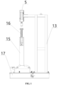
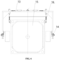
- the automatic cloth-vibrating and cake-removing trailer (hereinafter referred to as the cloth-vibrating and cake-removing trailer) has the key points of overall technological scheme that compared with the prior art, the innovative overall structure has the outstanding substantive characteristics that on the basis of an existing pull-plate cake discharging mechanism, a vehicle-mounted pneumatic vibrating device is improved into a trailer type pneumatic vibrating device: (1) movable trailer seats are creatively additionally arranged, so that the trailer type pneumatic vibrating device can be hung on the two pull-plate trolleys to work, and the trailer type pneumatic vibrating device can also be unhooked (separated from the two pull-plate trolleys) and stopped at the edge of a machine tailstock when necessary, so that normal work of the automatic filter cloth cleaning mechanism is not hindered, and the compatibility of automatic cloth vibration and cloth washing of the filter press is realized; (2) cantilever type air cylinder platforms are adaptively additionally arranged, two vibrating air cylinders are align
- the working process of the lifting type cloth washing mechanism 20 is as follows: (1) after the filter press automatically removes cakes, the automatic cloth-vibrating and cake-removing trailer 13 and the two pull-plate trolleys 17 are unhooked and stopped at the edge of the machine tailstock 21 when necessary, and under the control of the PLC control system 23, the pull-plate trolleys 17 automatically pull open the filter plates 15 to a cleaning position one by one (the limiting device acts); and (2) the lifting type cloth washing mechanism 20 and the pull-plate trolleys 17 synchronously operate and automatically lift, and the filter cloth 19 is automatically washed and smoothed by high-pressure water through the lifting pipeline and the washing transverse pipe, so that the filtration speed of the filter cloth 19 is increased, and the service life of the filter cloth 19 is prolonged.
Landscapes
- Chemical & Material Sciences (AREA)
- Chemical Kinetics & Catalysis (AREA)
- Filtration Of Liquid (AREA)
Claims (4)
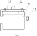
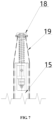
- Automatischer Tuchvibrations- und Kuchenentfernungsanhänger, umfassend:- eine pneumatische Vibrationsvorrichtung (1 vom Anhängertyp und- elastische Tuchvibrationsvorrichtungen (16),A) wobei die pneumatische Vibrationsvorrichtung (1) vom Anhängertyp Folgendes umfasst:- bewegliche Anhängeraufnahmen (2),- einen Anhängerrahmen (3) vom Klappentyp, der an die beweglichen Anhängeraufnahmen (2) geschweißt ist und sich in einer vertikalen Richtung erstreckt,- Luftzylinderplattformen (4) vom freitragenden Typ, die an den Anhängerrahmen (3) vom Klappentyp geschweißt sind und senkrecht dazu verlaufen und die sich in einer horizontalen Richtung erstrecken,- zwei Vibrationsluftzylinder (5), die mit den elastischen Tuchvibrationsvorrichtungen (16) ausgerichtet sind, wobei einer der zwei Vibrationsluftzylinder (5) vertikal an jeder der Luftzylinderplattformen (4) vom freitragenden Typ montiert ist,- zwei Luftspeicherbehälter (6),- zwei elektromagnetische Ventile (7) und- ein Dreiwegegelenk (8), das mittig an dem Anhängerrahmen (3) vom Klappentyp montiert ist und das extern mit einem Hochdruckgaseingangsschlauch verbunden ist; wobei jedes der zwei elektromagnetischen Ventile (7) und jeder der zwei Gasspeicherbehälter (6) nacheinander zwischen einem der zwei Vibrationsluftzylinder (5) bzw. dem Dreiwegegelenk (8) montiert ist, wobei einer der zwei Vibrationsluftzylinder (5) und ein Ende eines der zwei elektromagnetischen Ventile (7) durch einen Luftförderschlauch verbunden sind, ein anderes Ende des einen der elektromagnetischen Ventile (7) und ein Ende eines der zwei Luftspeicherbehälter (6) durch einen Luftförderschlauch verbunden sind, ein anderes Ende des einen der zwei Luftspeicherbehälter (6) und ein Ende des Dreiwegegelenks (8) durch einen Luftförderschlauch verbunden sind, ein anderes Ende des Dreiwegegelenks (8) und ein Ende des anderen einen der zwei Luftspeicherbehälter (6) durch einen Luftförderschlauch verbunden sind, ein anderes Ende des anderen einen der zwei zweiten Luftspeicherbehälter (6) und ein Ende des anderen einen der zwei elektromagnetischen Ventile (7) durch einen Luftförderschlauch verbunden sind, ein anderes Ende des anderen einen der zwei elektromagnetischen Ventile (7) und des anderen einen der zwei Vibrationsluftzylinder (5) durch einen Luftförderschlauch verbunden sind und wobei die zwei elektromagnetischen Ventile (7) extern mit einem SPS-Programmsteuerschrank (23) verbunden sind;wobei jede bewegliche Anhängeraufnahme (2) Folgendes umfasst:- einen Anhängeraufnahmenhauptkörper (9), wobei der Anhängeraufnahmenhauptkörper (9) eine C-förmige Anhängeraufnahme mit einer Öffnung ist, die zu einer Filterplatte (15) zeigt,- einen verschleißfesten Block (10), wobei der verschleißfeste Block (10) an einem oberen Teil in dem Anhängeraufnahmenhauptkörper (9) montiert ist,- eine Zugplatteninduktionsplatte (11), wobei die Zugplatteninduktionsplatte (11) eine Winkelstahlplatte ist, wobei zwei Löcher in einer oberen Kante der Zugplatteninduktionsplatte (11) gebildet sind und wobei eine Breite einer vorderen Kante der Zugplatteninduktionsplatte (11) größer als eine Wanddicke des Anhängeraufnahmenhauptkörpers (9) ist, sodass die Zugplatteninduktionsplatte (11) den verschleißfesten Block (10) daran hindert, nach außen zu gleiten; und- eine Anhängerstiftbaugruppe (12), wobei die Anhängerstiftbaugruppe (12) zwei Anhängerverbindungsvorsprünge und einen Anhängerverbindungsstift umfasst, wobei ein Verbindungsstifteinführungsloch in jedem der zwei Anhängerverbindungsvorsprünge gebildet ist, wobei jeder der zwei Anhängerverbindungsvorsprünge in einem angepassten Modus an jede Seite einer entsprechenden einen der beweglichen Anhängeraufnahmen (2) und jede Seite eines entsprechenden einen der zwei Zugplattenwagen (17) geschweißt ist und der Anhängerverbindungsstift in die Verbindungsstifteinführungslöcher der zwei Anhängerverbindungsvorsprünge eingesetzt ist;B) wobei jede elastische Tuchvibrationsvorrichtung (16) Folgendes umfasst:- eine Tuchvibrationsaufnahme,- eine Teleskopsäule, die auf der Tuchvibrationsaufnahme montiert ist,- eine Tuchaufhängestangenbaugruppe (18) und- eine Rückstellfeder, die die Teleskopsäule ummantelt;wobei die Tuchaufhängestangenbaugruppe (18) Folgendes umfasst:- eine Filtertuchdurchdringungs- und -aufhängestange,- eine Tuchzugstange und- eine Tuchaufhängestangenummantelung, wobei die Tuchaufhängestangenummantelung an der Teleskopsäule montiert ist;wobei die Tuchvibrationsaufnahme auf jeder Seite eines oberen Endes der Filterplatte (15) montiert ist, auf der ein Filtertuch (19) umwickelt ist;wobei das Filtertuch (19) an der Filtertuchdurchdringungs- und -aufhängestange aufgehängt ist, wobei die Filtertuchdurchdringungs- und -aufhängestange in der Tuchaufhängestangenummantelung montiert ist und die Tuchzugstange in einem Durchdringungsmodus an einem unteren Ende des Filtertuchs (19) montiert ist;C) wobei die pneumatische Vibrationsvorrichtung (1) vom Anhängertyp durch die Anhängerstiftbaugruppe (12) an den zwei Zugplattenwagen (17) aufgehängt ist und sich synchron mit den zwei Zugplattenwagen (17) bewegen kann;wobei, falls erforderlich, die pneumatische Vibrationsvorrichtung (1) auch an einer Kante eines Maschinenreitstocks (21) ausgehakt und angehalten werden kann; unddie pneumatische Vibrationsvorrichtung vom Anhängertyp Funktionen einer automatischen Tuchvibration aufweist, um das Entfernen und Aushaken von Kuchen zu unterstützen.
- Automatischer Tuchvibrations- und Kuchenentfernungsanhänger nach Anspruch 1, wobei ein Innendurchmesser von jedem Anhängeraufnahmenhauptkörper (9) mit jeder der Zugplattenwagengleitführungen übereinstimmt und eine Länge von jedem Anhängeraufnahmenhauptkörper (9) größer als eine Breite (Dicke) des Anhängerrahmens (3) vom Klappentyp ist; wobei jeder verschleißfeste Block (10) ein nutförmiger verschleißfester Block (10) ist, eine Nutöffnung jedes verschleißfesten Blocks (10) in Spielpassung mit einer entsprechenden Gleitführung des Zugplattenwagens (17) ist, eine Länge jedes verschleißfesten Blocks (10) dem Innendurchmesser des Anhängeraufnahmenhauptkörpers (9) entspricht und jeder verschleißfeste Block (10) durch Polypropylen-Spritzgießen gebildet ist.
- Automatischer Tuchvibrations- und Kuchenentfernungsanhänger nach Anspruch 1, wobei der Anhängerrahmen (3) vom Klappentyp ein doppellagiger Rahmen vom Klappentyp ist, eine Verbindungsplatte zwischen zwei Lagen des doppellagigen Rahmens vom Klappentyp angeordnet ist, dreieckige Stabilisatorplatten an einer linken oberen Ecke und einer rechten oberen Ecke angeordnet sind, eine Breite des Anhängerrahmens (3) vom Klappentyp einem Abstand zwischen den zwei Gleitführungen des Zugplattenwagens (17) entspricht, eine Höhe des Anhängerrahmens (3) vom Klappentyp sich den Vibrationsluftzylindern (5) anpasst, um die elastischen Tuchvibrationsvorrichtungen (16) zu vibrieren, und ein Vierkantrohrmaterial aus Edelstahl übernommen wird; und
wobei Vibrationsluftzylindermontagelöcher in den Luftzylinderplattformen (4) vom freitragenden Typ gebildet sind, sich die Armlängen der Luftzylinderplattformen (4) vom freitragenden Typ an die Vibrationsluftzylinder (5) anpassen und mit den elastischen Tuchvibrationsvorrichtungen (16) ausgerichtet werden können und das Vierkantrohrmaterial aus Edelstahl übernommen wird. - Automatische tuchvibrations- und tuchwaschkompatible Filterpresse, die eine automatische Filterpresse ist, die mit Tuchvibration und Tuchwäsche kompatibel ist, umfassend- ein Doppelträgergestell,- einen Filterplattendruckmechanismus,- einen Filtermechanismus mit mehreren Filterkammern,- einen Zugplatten-Kuchenentladungsmechanismus,- einen Tuchvibrations- und Kuchenentfernungsanhänger des Zugplatten-Kuchenentladungsmechanismus,- eine Tuchwaschmechanismus (20) vom Hebetyp,- einen Flüssigkeitsaufnahmeplatten-Umstülpungsmechanismus und- ein SPS-Programmsteuersystem (23),wobei der Tuchvibrations- und Kuchenentfernungsanhänger der automatische Tuchvibrations- und Kuchenentfernungsanhänger nach den Ansprüchen 1 bis 3 ist; undwobei der Tuchvibrations- und Kuchenentfernungsanhänger mehrere Funktionen zum automatischen Aufziehen der Filterplatten, automatischen Vibrieren des Tuches, um das Entfernen des Kuchens zu unterstützen, und automatischen Reinigen des Filtertuchs aufweist.
Applications Claiming Priority (1)
| Application Number | Priority Date | Filing Date | Title |
|---|---|---|---|
| CN202110402881.XA CN112892012B (zh) | 2021-04-15 | 2021-04-15 | 自动振布脱饼挂车及相应自动振布与洗布兼容式压滤机 |
Publications (2)
| Publication Number | Publication Date |
|---|---|
| EP4074396A1 EP4074396A1 (de) | 2022-10-19 |
| EP4074396B1 true EP4074396B1 (de) | 2025-07-09 |
Family
ID=76110534
Family Applications (1)
| Application Number | Title | Priority Date | Filing Date |
|---|---|---|---|
| EP21190324.0A Active EP4074396B1 (de) | 2021-04-15 | 2021-08-09 | Automatischer tuchvibrations- und kuchenentfernungsanhänger und entsprechende automatische tuchvibrations- und tuchwaschkompatible filterpresse |
Country Status (2)
| Country | Link |
|---|---|
| EP (1) | EP4074396B1 (de) |
| CN (1) | CN112892012B (de) |
Families Citing this family (3)
| Publication number | Priority date | Publication date | Assignee | Title |
|---|---|---|---|---|
| CN112892012B (zh) * | 2021-04-15 | 2024-07-23 | 景津装备股份有限公司 | 自动振布脱饼挂车及相应自动振布与洗布兼容式压滤机 |
| CN113384926B (zh) * | 2021-07-20 | 2024-07-23 | 景津装备股份有限公司 | 一种自动振布挂车的自动脱离装置 |
| CN117225041B (zh) * | 2023-08-24 | 2025-11-14 | 安徽万磁电子股份有限公司 | 一种球磨车间废水处理工艺 |
Family Cites Families (12)
| Publication number | Priority date | Publication date | Assignee | Title |
|---|---|---|---|---|
| US4209404A (en) * | 1975-05-22 | 1980-06-24 | Ngk Insulators, Ltd. | Filter press |
| DE3007404A1 (de) * | 1979-04-05 | 1980-10-23 | Ishigaki Mech Ind | Vorrichtung zum entfernen der filterkuchen bei einer filterpresse |
| JP3495811B2 (ja) * | 1995-02-28 | 2004-02-09 | 株式会社栗田機械製作所 | フイルタプレスの濾布掛け装置 |
| CN2796796Y (zh) * | 2005-04-16 | 2006-07-19 | 王兆群 | 一种压滤机机上洗布装置 |
| CN100591402C (zh) * | 2006-08-01 | 2010-02-24 | 杭州兴源过滤科技股份有限公司 | 压滤机滤布曲张振打机构及振打方法 |
| CN101485942B (zh) * | 2009-01-10 | 2011-10-19 | 杭州兴源过滤科技股份有限公司 | 压滤机气液伸缩振打水冲洗装置及曲张振打水冲洗方法 |
| CN101601942B (zh) * | 2009-07-07 | 2011-04-13 | 景津压滤机集团有限公司 | 压滤机滤板分组振打装置 |
| CN207822588U (zh) * | 2018-01-04 | 2018-09-07 | 景津环保股份有限公司 | 一种气动振打卸饼压滤机 |
| CN112044129A (zh) * | 2020-09-15 | 2020-12-08 | 景津环保股份有限公司 | 自动振布脱饼装置及相应自动脱饼压滤机 |
| CN212818345U (zh) * | 2020-10-20 | 2021-03-30 | 中大贝莱特压滤机有限公司 | 滤布支撑机构及卸饼机构 |
| CN214763540U (zh) * | 2021-04-15 | 2021-11-19 | 景津环保股份有限公司 | 自动振布脱饼挂车及相应自动振布与洗布兼容式压滤机 |
| CN112892012B (zh) * | 2021-04-15 | 2024-07-23 | 景津装备股份有限公司 | 自动振布脱饼挂车及相应自动振布与洗布兼容式压滤机 |
-
2021
- 2021-04-15 CN CN202110402881.XA patent/CN112892012B/zh active Active
- 2021-08-09 EP EP21190324.0A patent/EP4074396B1/de active Active
Also Published As
| Publication number | Publication date |
|---|---|
| CN112892012A (zh) | 2021-06-04 |
| EP4074396A1 (de) | 2022-10-19 |
| CN112892012B (zh) | 2024-07-23 |
Similar Documents
| Publication | Publication Date | Title |
|---|---|---|
| EP4074396B1 (de) | Automatischer tuchvibrations- und kuchenentfernungsanhänger und entsprechende automatische tuchvibrations- und tuchwaschkompatible filterpresse | |
| CN101293152B (zh) | 一种卧式压滤机 | |
| EP2452736B1 (de) | Gruppierung von schwingungsvorrichtungen für filterplatten eines pressfilters | |
| EP2692403B1 (de) | Abstreifervorrichtung zum entladen eines filterkuchens auf der filterplatte eines druckfilters | |
| CN102389659B (zh) | 压滤机快速卸饼和清洗滤布装置 | |
| CN201482269U (zh) | 一种卧式压滤机 | |
| CN214763540U (zh) | 自动振布脱饼挂车及相应自动振布与洗布兼容式压滤机 | |
| JPH0133128Y2 (de) | ||
| CN108176090A (zh) | 滤板单元的拖动装置 | |
| CN214232929U (zh) | 一种板框式压滤机 | |
| CN202270397U (zh) | 压滤机快速卸饼和清洗滤布装置 | |
| CN213134298U (zh) | 一种清洗机 | |
| CN112044129A (zh) | 自动振布脱饼装置及相应自动脱饼压滤机 | |
| CN112495013A (zh) | 一种压滤机滤饼自动刮铲装置 | |
| CN119971571A (zh) | 一种利用分组拉板辅助卸泥的自动压滤机及卸泥控制方法 | |
| CN210448217U (zh) | 一种滤板安装滤布自动吊板装置 | |
| CN110090840B (zh) | 醋缸清洗机组 | |
| JPH10216414A (ja) | フィルタープレスの濾布自動洗浄装置 | |
| CN2675222Y (zh) | 全自动压滤机的自动刮泥及滤布清洗装置 | |
| CN214634306U (zh) | 一种清理进料口的自动装置 | |
| CN217661709U (zh) | 分组清洗滤布机构的自匀板快接管式升降喷水横管装置 | |
| CN212818345U (zh) | 滤布支撑机构及卸饼机构 | |
| CN212119145U (zh) | 气动振板的储气装置及相应振抖式拉板小车 | |
| CN214861460U (zh) | 一次拉开滤板式压滤机的清洗滤布装置及相应小型压滤机 | |
| CN212440219U (zh) | 自动振布脱饼装置及相应自动脱饼压滤机 |
Legal Events
| Date | Code | Title | Description |
|---|---|---|---|
| PUAI | Public reference made under article 153(3) epc to a published international application that has entered the european phase |
Free format text: ORIGINAL CODE: 0009012 |
|
| STAA | Information on the status of an ep patent application or granted ep patent |
Free format text: STATUS: REQUEST FOR EXAMINATION WAS MADE |
|
| 17P | Request for examination filed |
Effective date: 20210809 |
|
| AK | Designated contracting states |
Kind code of ref document: A1 Designated state(s): AL AT BE BG CH CY CZ DE DK EE ES FI FR GB GR HR HU IE IS IT LI LT LU LV MC MK MT NL NO PL PT RO RS SE SI SK SM TR |
|
| P01 | Opt-out of the competence of the unified patent court (upc) registered |
Effective date: 20230526 |
|
| STAA | Information on the status of an ep patent application or granted ep patent |
Free format text: STATUS: EXAMINATION IS IN PROGRESS |
|
| 17Q | First examination report despatched |
Effective date: 20230907 |
|
| GRAP | Despatch of communication of intention to grant a patent |
Free format text: ORIGINAL CODE: EPIDOSNIGR1 |
|
| STAA | Information on the status of an ep patent application or granted ep patent |
Free format text: STATUS: GRANT OF PATENT IS INTENDED |
|
| INTG | Intention to grant announced |
Effective date: 20250327 |
|
| GRAS | Grant fee paid |
Free format text: ORIGINAL CODE: EPIDOSNIGR3 |
|
| GRAA | (expected) grant |
Free format text: ORIGINAL CODE: 0009210 |
|
| STAA | Information on the status of an ep patent application or granted ep patent |
Free format text: STATUS: THE PATENT HAS BEEN GRANTED |
|
| AK | Designated contracting states |
Kind code of ref document: B1 Designated state(s): AL AT BE BG CH CY CZ DE DK EE ES FI FR GB GR HR HU IE IS IT LI LT LU LV MC MK MT NL NO PL PT RO RS SE SI SK SM TR |
|
| REG | Reference to a national code |
Ref country code: GB Ref legal event code: FG4D |
|
| REG | Reference to a national code |
Ref country code: CH Ref legal event code: EP |
|
| REG | Reference to a national code |
Ref country code: IE Ref legal event code: FG4D |
|
| REG | Reference to a national code |
Ref country code: DE Ref legal event code: R096 Ref document number: 602021033662 Country of ref document: DE |
|
| PGFP | Annual fee paid to national office [announced via postgrant information from national office to epo] |
Ref country code: DE Payment date: 20250903 Year of fee payment: 5 |
|
| PGFP | Annual fee paid to national office [announced via postgrant information from national office to epo] |
Ref country code: AT Payment date: 20251020 Year of fee payment: 5 Ref country code: FR Payment date: 20250904 Year of fee payment: 5 |
|
| REG | Reference to a national code |
Ref country code: NL Ref legal event code: MP Effective date: 20250709 |
|
| PG25 | Lapsed in a contracting state [announced via postgrant information from national office to epo] |
Ref country code: PT Free format text: LAPSE BECAUSE OF FAILURE TO SUBMIT A TRANSLATION OF THE DESCRIPTION OR TO PAY THE FEE WITHIN THE PRESCRIBED TIME-LIMIT Effective date: 20251110 |
|
| PG25 | Lapsed in a contracting state [announced via postgrant information from national office to epo] |
Ref country code: NL Free format text: LAPSE BECAUSE OF FAILURE TO SUBMIT A TRANSLATION OF THE DESCRIPTION OR TO PAY THE FEE WITHIN THE PRESCRIBED TIME-LIMIT Effective date: 20250709 |
|
| REG | Reference to a national code |
Ref country code: AT Ref legal event code: MK05 Ref document number: 1811348 Country of ref document: AT Kind code of ref document: T Effective date: 20250709 |
|
| PG25 | Lapsed in a contracting state [announced via postgrant information from national office to epo] |
Ref country code: IS Free format text: LAPSE BECAUSE OF FAILURE TO SUBMIT A TRANSLATION OF THE DESCRIPTION OR TO PAY THE FEE WITHIN THE PRESCRIBED TIME-LIMIT Effective date: 20251109 |
|
| PG25 | Lapsed in a contracting state [announced via postgrant information from national office to epo] |
Ref country code: NO Free format text: LAPSE BECAUSE OF FAILURE TO SUBMIT A TRANSLATION OF THE DESCRIPTION OR TO PAY THE FEE WITHIN THE PRESCRIBED TIME-LIMIT Effective date: 20251009 |
|
| REG | Reference to a national code |
Ref country code: LT Ref legal event code: MG9D |
|
| PG25 | Lapsed in a contracting state [announced via postgrant information from national office to epo] |
Ref country code: AT Free format text: LAPSE BECAUSE OF FAILURE TO SUBMIT A TRANSLATION OF THE DESCRIPTION OR TO PAY THE FEE WITHIN THE PRESCRIBED TIME-LIMIT Effective date: 20250709 |
|
| PG25 | Lapsed in a contracting state [announced via postgrant information from national office to epo] |
Ref country code: FI Free format text: LAPSE BECAUSE OF FAILURE TO SUBMIT A TRANSLATION OF THE DESCRIPTION OR TO PAY THE FEE WITHIN THE PRESCRIBED TIME-LIMIT Effective date: 20250709 |
|
| PG25 | Lapsed in a contracting state [announced via postgrant information from national office to epo] |
Ref country code: HR Free format text: LAPSE BECAUSE OF FAILURE TO SUBMIT A TRANSLATION OF THE DESCRIPTION OR TO PAY THE FEE WITHIN THE PRESCRIBED TIME-LIMIT Effective date: 20250709 |
|
| PG25 | Lapsed in a contracting state [announced via postgrant information from national office to epo] |
Ref country code: GR Free format text: LAPSE BECAUSE OF FAILURE TO SUBMIT A TRANSLATION OF THE DESCRIPTION OR TO PAY THE FEE WITHIN THE PRESCRIBED TIME-LIMIT Effective date: 20251010 |
|
| PG25 | Lapsed in a contracting state [announced via postgrant information from national office to epo] |
Ref country code: SE Free format text: LAPSE BECAUSE OF FAILURE TO SUBMIT A TRANSLATION OF THE DESCRIPTION OR TO PAY THE FEE WITHIN THE PRESCRIBED TIME-LIMIT Effective date: 20250709 |
|
| PG25 | Lapsed in a contracting state [announced via postgrant information from national office to epo] |
Ref country code: LV Free format text: LAPSE BECAUSE OF FAILURE TO SUBMIT A TRANSLATION OF THE DESCRIPTION OR TO PAY THE FEE WITHIN THE PRESCRIBED TIME-LIMIT Effective date: 20250709 |
|
| PG25 | Lapsed in a contracting state [announced via postgrant information from national office to epo] |
Ref country code: PL Free format text: LAPSE BECAUSE OF FAILURE TO SUBMIT A TRANSLATION OF THE DESCRIPTION OR TO PAY THE FEE WITHIN THE PRESCRIBED TIME-LIMIT Effective date: 20250709 Ref country code: BG Free format text: LAPSE BECAUSE OF FAILURE TO SUBMIT A TRANSLATION OF THE DESCRIPTION OR TO PAY THE FEE WITHIN THE PRESCRIBED TIME-LIMIT Effective date: 20250709 |
|
| PG25 | Lapsed in a contracting state [announced via postgrant information from national office to epo] |
Ref country code: RS Free format text: LAPSE BECAUSE OF FAILURE TO SUBMIT A TRANSLATION OF THE DESCRIPTION OR TO PAY THE FEE WITHIN THE PRESCRIBED TIME-LIMIT Effective date: 20251009 |
|
| PG25 | Lapsed in a contracting state [announced via postgrant information from national office to epo] |
Ref country code: ES Free format text: LAPSE BECAUSE OF FAILURE TO SUBMIT A TRANSLATION OF THE DESCRIPTION OR TO PAY THE FEE WITHIN THE PRESCRIBED TIME-LIMIT Effective date: 20250709 |
|
| PG25 | Lapsed in a contracting state [announced via postgrant information from national office to epo] |
Ref country code: RO Free format text: LAPSE BECAUSE OF FAILURE TO SUBMIT A TRANSLATION OF THE DESCRIPTION OR TO PAY THE FEE WITHIN THE PRESCRIBED TIME-LIMIT Effective date: 20250709 |
|
| REG | Reference to a national code |
Ref country code: CH Ref legal event code: H13 Free format text: ST27 STATUS EVENT CODE: U-0-0-H10-H13 (AS PROVIDED BY THE NATIONAL OFFICE) Effective date: 20260324 |
|
| PG25 | Lapsed in a contracting state [announced via postgrant information from national office to epo] |
Ref country code: SM Free format text: LAPSE BECAUSE OF FAILURE TO SUBMIT A TRANSLATION OF THE DESCRIPTION OR TO PAY THE FEE WITHIN THE PRESCRIBED TIME-LIMIT Effective date: 20250709 |
|
| PG25 | Lapsed in a contracting state [announced via postgrant information from national office to epo] |
Ref country code: DK Free format text: LAPSE BECAUSE OF FAILURE TO SUBMIT A TRANSLATION OF THE DESCRIPTION OR TO PAY THE FEE WITHIN THE PRESCRIBED TIME-LIMIT Effective date: 20250709 |
|
| PG25 | Lapsed in a contracting state [announced via postgrant information from national office to epo] |
Ref country code: LU Free format text: LAPSE BECAUSE OF NON-PAYMENT OF DUE FEES Effective date: 20250809 Ref country code: IT Free format text: LAPSE BECAUSE OF FAILURE TO SUBMIT A TRANSLATION OF THE DESCRIPTION OR TO PAY THE FEE WITHIN THE PRESCRIBED TIME-LIMIT Effective date: 20250709 |
|
| PG25 | Lapsed in a contracting state [announced via postgrant information from national office to epo] |
Ref country code: CH Free format text: LAPSE BECAUSE OF NON-PAYMENT OF DUE FEES Effective date: 20250831 Ref country code: CZ Free format text: LAPSE BECAUSE OF FAILURE TO SUBMIT A TRANSLATION OF THE DESCRIPTION OR TO PAY THE FEE WITHIN THE PRESCRIBED TIME-LIMIT Effective date: 20250709 |
|
| PG25 | Lapsed in a contracting state [announced via postgrant information from national office to epo] |
Ref country code: SK Free format text: LAPSE BECAUSE OF FAILURE TO SUBMIT A TRANSLATION OF THE DESCRIPTION OR TO PAY THE FEE WITHIN THE PRESCRIBED TIME-LIMIT Effective date: 20250709 Ref country code: EE Free format text: LAPSE BECAUSE OF FAILURE TO SUBMIT A TRANSLATION OF THE DESCRIPTION OR TO PAY THE FEE WITHIN THE PRESCRIBED TIME-LIMIT Effective date: 20250709 |