EP2452034B1 - Dispositif à enroulement pour l'occlusion d'ouvertures pratiquées dans des murs ou de fenêtres - Google Patents
Dispositif à enroulement pour l'occlusion d'ouvertures pratiquées dans des murs ou de fenêtres Download PDFInfo
- Publication number
- EP2452034B1 EP2452034B1 EP10743015.9A EP10743015A EP2452034B1 EP 2452034 B1 EP2452034 B1 EP 2452034B1 EP 10743015 A EP10743015 A EP 10743015A EP 2452034 B1 EP2452034 B1 EP 2452034B1
- Authority
- EP
- European Patent Office
- Prior art keywords
- cord
- longitudinal edge
- cover element
- raising
- winding device
- Prior art date
- Legal status (The legal status is an assumption and is not a legal conclusion. Google has not performed a legal analysis and makes no representation as to the accuracy of the status listed.)
- Not-in-force
Links
- 238000004804 winding Methods 0.000 title claims description 122
- 230000033001 locomotion Effects 0.000 claims description 48
- 238000000034 method Methods 0.000 claims description 12
- 239000004744 fabric Substances 0.000 description 41
- 230000008569 process Effects 0.000 description 6
- 230000008901 benefit Effects 0.000 description 5
- 230000005540 biological transmission Effects 0.000 description 3
- 239000011295 pitch Substances 0.000 description 3
- 238000005096 rolling process Methods 0.000 description 3
- 230000000087 stabilizing effect Effects 0.000 description 3
- 230000008859 change Effects 0.000 description 2
- 230000000694 effects Effects 0.000 description 2
- 238000005516 engineering process Methods 0.000 description 2
- 239000000463 material Substances 0.000 description 2
- 230000002787 reinforcement Effects 0.000 description 2
- 230000006641 stabilisation Effects 0.000 description 2
- 238000011105 stabilization Methods 0.000 description 2
- 239000000853 adhesive Substances 0.000 description 1
- 230000001070 adhesive effect Effects 0.000 description 1
- 238000005452 bending Methods 0.000 description 1
- 238000010276 construction Methods 0.000 description 1
- 230000006378 damage Effects 0.000 description 1
- 230000006735 deficit Effects 0.000 description 1
- 238000007599 discharging Methods 0.000 description 1
- 238000009434 installation Methods 0.000 description 1
- 238000012986 modification Methods 0.000 description 1
- 230000004048 modification Effects 0.000 description 1
- 230000001105 regulatory effect Effects 0.000 description 1
- 230000001360 synchronised effect Effects 0.000 description 1
- 238000009423 ventilation Methods 0.000 description 1
- 230000037303 wrinkles Effects 0.000 description 1
Images


Classifications
-
- E—FIXED CONSTRUCTIONS
- E06—DOORS, WINDOWS, SHUTTERS, OR ROLLER BLINDS IN GENERAL; LADDERS
- E06B—FIXED OR MOVABLE CLOSURES FOR OPENINGS IN BUILDINGS, VEHICLES, FENCES OR LIKE ENCLOSURES IN GENERAL, e.g. DOORS, WINDOWS, BLINDS, GATES
- E06B9/00—Screening or protective devices for wall or similar openings, with or without operating or securing mechanisms; Closures of similar construction
- E06B9/24—Screens or other constructions affording protection against light, especially against sunshine; Similar screens for privacy or appearance; Slat blinds
- E06B9/40—Roller blinds
-
- E—FIXED CONSTRUCTIONS
- E04—BUILDING
- E04F—FINISHING WORK ON BUILDINGS, e.g. STAIRS, FLOORS
- E04F10/00—Sunshades, e.g. Florentine blinds or jalousies; Outside screens; Awnings or baldachins
- E04F10/02—Sunshades, e.g. Florentine blinds or jalousies; Outside screens; Awnings or baldachins of flexible canopy materials, e.g. canvas ; Baldachins
- E04F10/06—Sunshades, e.g. Florentine blinds or jalousies; Outside screens; Awnings or baldachins of flexible canopy materials, e.g. canvas ; Baldachins comprising a roller-blind with means for holding the end away from a building
- E04F10/0644—Sunshades, e.g. Florentine blinds or jalousies; Outside screens; Awnings or baldachins of flexible canopy materials, e.g. canvas ; Baldachins comprising a roller-blind with means for holding the end away from a building with mechanisms for unrolling or balancing the blind
- E04F10/0655—Sunshades, e.g. Florentine blinds or jalousies; Outside screens; Awnings or baldachins of flexible canopy materials, e.g. canvas ; Baldachins comprising a roller-blind with means for holding the end away from a building with mechanisms for unrolling or balancing the blind acting on the movable end, e.g. front bar
-
- E—FIXED CONSTRUCTIONS
- E06—DOORS, WINDOWS, SHUTTERS, OR ROLLER BLINDS IN GENERAL; LADDERS
- E06B—FIXED OR MOVABLE CLOSURES FOR OPENINGS IN BUILDINGS, VEHICLES, FENCES OR LIKE ENCLOSURES IN GENERAL, e.g. DOORS, WINDOWS, BLINDS, GATES
- E06B9/00—Screening or protective devices for wall or similar openings, with or without operating or securing mechanisms; Closures of similar construction
- E06B9/24—Screens or other constructions affording protection against light, especially against sunshine; Similar screens for privacy or appearance; Slat blinds
- E06B9/40—Roller blinds
- E06B9/42—Parts or details of roller blinds, e.g. suspension devices, blind boxes
- E06B9/44—Rollers therefor; Fastening roller blinds to rollers
-
- E—FIXED CONSTRUCTIONS
- E06—DOORS, WINDOWS, SHUTTERS, OR ROLLER BLINDS IN GENERAL; LADDERS
- E06B—FIXED OR MOVABLE CLOSURES FOR OPENINGS IN BUILDINGS, VEHICLES, FENCES OR LIKE ENCLOSURES IN GENERAL, e.g. DOORS, WINDOWS, BLINDS, GATES
- E06B9/00—Screening or protective devices for wall or similar openings, with or without operating or securing mechanisms; Closures of similar construction
- E06B9/56—Operating, guiding or securing devices or arrangements for roll-type closures; Spring drums; Tape drums; Counterweighting arrangements therefor
- E06B9/66—Operating, guiding or securing devices or arrangements for roll-type closures; Spring drums; Tape drums; Counterweighting arrangements therefor with a roller situated at the bottom
-
- E—FIXED CONSTRUCTIONS
- E04—BUILDING
- E04F—FINISHING WORK ON BUILDINGS, e.g. STAIRS, FLOORS
- E04F10/00—Sunshades, e.g. Florentine blinds or jalousies; Outside screens; Awnings or baldachins
- E04F10/02—Sunshades, e.g. Florentine blinds or jalousies; Outside screens; Awnings or baldachins of flexible canopy materials, e.g. canvas ; Baldachins
- E04F10/06—Sunshades, e.g. Florentine blinds or jalousies; Outside screens; Awnings or baldachins of flexible canopy materials, e.g. canvas ; Baldachins comprising a roller-blind with means for holding the end away from a building
- E04F10/0644—Sunshades, e.g. Florentine blinds or jalousies; Outside screens; Awnings or baldachins of flexible canopy materials, e.g. canvas ; Baldachins comprising a roller-blind with means for holding the end away from a building with mechanisms for unrolling or balancing the blind
- E04F10/0648—Sunshades, e.g. Florentine blinds or jalousies; Outside screens; Awnings or baldachins of flexible canopy materials, e.g. canvas ; Baldachins comprising a roller-blind with means for holding the end away from a building with mechanisms for unrolling or balancing the blind acting on the roller tube
-
- E—FIXED CONSTRUCTIONS
- E06—DOORS, WINDOWS, SHUTTERS, OR ROLLER BLINDS IN GENERAL; LADDERS
- E06B—FIXED OR MOVABLE CLOSURES FOR OPENINGS IN BUILDINGS, VEHICLES, FENCES OR LIKE ENCLOSURES IN GENERAL, e.g. DOORS, WINDOWS, BLINDS, GATES
- E06B9/00—Screening or protective devices for wall or similar openings, with or without operating or securing mechanisms; Closures of similar construction
- E06B9/24—Screens or other constructions affording protection against light, especially against sunshine; Similar screens for privacy or appearance; Slat blinds
- E06B9/40—Roller blinds
- E06B2009/405—Two rollers
Definitions
- the present invention relates to a winding device for covering wall openings or windows with the features of claim 1.
- winding and unwinding winding devices are already known in the vertical direction.
- Such winding devices come, for example, for variable shielding of rooms, for variable ventilation and / or foreclosure of animal houses, greenhouses or the like for use.
- Such winding devices have flexibly configured fabrics for covering.
- winding coils are known, on which the flexible fabric can be wound up.
- Such a winding device is for example in the DE 201 17 865 U1 disclosed.
- a flexible fabric 2 can be wound on a lower shaft 4, which is driven by a motor.
- the shaft 40 rotatable about a horizontal axis D moves upward in the vertical direction.
- the flexible fabric 2 is fixed at its upper end with ropes 25 on a second shaft, a so-called bobbin 24. This is used to set a fixed gap opening between the second shaft 24 and tissue 2.
- the fabric 2 must carry the weight of the shaft 4 during winding. This leads to a tensile stress on the fabric 2. Due to the stress, the fabric 2 can be damaged under unfavorable circumstances.
- the diameter of the shaft 4 increases with the fabric 2 wound thereon gradually. At a constant rotational speed of the rotating shaft 4, this results in an accelerated movement of the fabric 2 during the winding-up process.
- Another winding device is in GB 2 431 190 A described.
- the fabric material 1 is arranged between two shafts 2 and 3, which can each perform a translational and rotating movement. The adjustment of the size and position of the fabric 1 is effected by appropriate movement of the two shafts 2 and 3.
- the object of the invention is to provide a simple as possible, cost-effective and universally applicable winding device for covering wall openings or windows ready in the tissue and is unwound.
- the winding device includes a roll-up Covering element, a wavy trained or formed only by a lower seam or a lower fabric or longitudinal edge deflecting element and at least one lifting and lowering device.
- the cover also has an upper, preferably arranged parallel to the deflecting longitudinal edge.
- the lower longitudinal edge is either connected to the deflecting element or formed by this, so that by a rotation of the deflecting element or the lower fabric or longitudinal edge about a horizontal axis, the cover is rolled up or unrolled.
- the lifting and lowering device comprises at least one cable, wherein at least one free end of the cable is connected to the lifting and lowering device.
- the cable is arranged so that it engages around the cover, so that the deflecting element or the lower longitudinal edge is guided in the cable bend.
- the at least one rope can be in two opposite to each other Movement directions are guided.
- the cable may be connected to the upper longitudinal edge of the cover.
- rope must be construed broadly in context in terms of its conceptual definition, since for the rope, for example, chain-like structures or other deflectable elongated connecting elements can be selected. Also bands, strips or even wider tissue sections can be used for this purpose and should therefore be included in the selected term of the rope.
- the deflecting element or the lower longitudinal edge is arranged at the lowest point and guided in a cable bend and hangs, the lower longitudinal edge or the deflecting element is set in rotation by movement of the rope and rolls the tissue or the curtain on it automatically.
- the deflecting element or the lower longitudinal edge is set in rotation by the movement of the at least one cable in two directions of movement which are opposite to one another.
- the at least one cable can be guided at least approximately parallel in two relatively opposite directions of movement and simultaneously performs the deflection or the lower longitudinal edge and thus the up or rolling cover.
- the cover is thus set in rotation and the tissue or the curtain while up and unrolled.
- the ropes can also run obliquely, without any impairment of the function or otherwise limiting the invention is connected.
- the ropes can be arranged in an advantageous alternative of the invention optionally also in V-shape, which, for example, can have advantages in terms of the ropes to be wound or the space required for this.
- the variant to be selected depends primarily on the installation and space conditions and possibly on the preferred winding ratio.
- the winding device according to the invention for covering wall openings or windows can be used for example in stables or greenhouses and used meaningfully.
- the roll-up cover can be formed for example by a fabric or by interconnected plastic slats o. The like.
- the wavy deflecting element could optionally guide grooves or radial depressions o. The like.
- the rolled-up covering element envelops the deflection element or the seam of the cover element after just a short revolution, the cable no longer touches these grooves or radial depressions, so that they are dispensable and can optionally be dispensed with.
- the deflecting element With regard to its length and its diameter, a large number of possible variations is provided for the deflecting element.
- the width of the cover and thus the length of the deflecting element are preferably defined by the width of the opening to be covered.
- the width of the cover and thus the length of the deflecting element are preferably defined by the width of the opening to be covered.
- the at least one cable can - as already stated - arranged at least one of its free ends on the lifting and lowering device and be connected in certain embodiments of the invention with the upper longitudinal edge of the cover.
- the upper fabric or longitudinal edge of the cover is lowered or raised.
- the cover element has an upper and a lower longitudinal edge, which is preferably arranged parallel to the deflection element or which forms the deflection element.
- the longitudinal edges can be additionally provided with reinforcements for stabilization.
- the lower longitudinal edge of the cover is connected to the deflecting element or even forms the deflecting element, so that by a rotation of the deflecting element or the lower longitudinal edge about a horizontal axis of rotation, the cover on the deflecting element or at the lower longitudinal edge can be rolled up.
- the horizontally arranged axis runs through the deflecting element.
- the connection between deflecting element (if present) and lower longitudinal edge of the cover element can be subject to numerous design variations. For example, the connection can be made by rivet screw or adhesive connections.
- the lifting and lowering device is a shaft. At least one free end of the cable is thus arranged on the shaft in this embodiment. If the shaft is now placed in a rotating motion, then in a first step the cable and thus also the cover element are drained and at the same time the cover element is rolled up on the deflection element. If the cover is completely rolled up, so in a second step, the movement of the deflector in a vertical upward direction.
- the number of ropes used are the user in the context of Invention no limits. For example, multiple ropes can be used with longer cover elements.
- a cable is provided instead of a shaft.
- guide rollers may be present, which deflect the rope, for example, from its vertical direction of movement in a horizontal direction of movement.
- the synchronous speed of the winding speed has been found with the Auflass- and lifting speed of the fabric.
- the winding speed of the cover depends, for example, upon attachment of at least one free end of at least one cable to a shaft disposed above the cover from the winding speed of the at least one cable, which is necessary for winding the cover and for generating its winding and Abwickelrotation.
- the drive of the lifting and lowering device in particular the rotational movement of the shaft or the horizontal movement of a cable can be selectively generated by manual operation.
- a crank may be arranged on the shaft, by means of which the user can effect the rotation of the shaft, the horizontal movement of the cable.
- the drive of the lifting and lowering device is generated by a drive unit.
- the drive unit may be a motor, for example an electric motor.
- first cable and at least one second cable can be provided.
- the second cable can be provided for lifting and lowering the upper longitudinal edge, while the first cable is provided for winding the cover element or for winding and lifting or lowering the cover element.
- the ropes can be configured in terms of power optimized in terms of number, material and diameter. In particular, the term rope must also be broadly interpreted in this context in terms of its conceptual definition.
- the second cable may, for example, be arranged with its first free end on the lifting and lowering device, for example on a shaft, and with its second free end on the upper longitudinal edge of the covering element.
- the first cable can be arranged for example with two free ends on the lifting and lowering device, for example on a shaft.
- first cable is arranged with a free end on the lifting and lowering device, for example on a shaft and with its second free end on the upper longitudinal edge of the cover, wherein the first cable surrounds the cover.
- second cable is arranged with a free end on the lifting and lowering device, for example on a shaft and with its second free end on the upper longitudinal edge of the cover.
- the cover by rotation of the deflecting element or the lower longitudinal edge of the cover is wound on this. In particular, a largely complete winding takes place.
- the wound cover element By lifting the at least one first cable and / or the at least one second cable, the wound cover element can also be raised.
- the deflecting element does not necessarily have to mean a rigid part or even a separate part of the winding device according to the invention.
- the deflecting element can, for example, through the lower fabric seam or through the lower fabric edge be formed, which turns through the articulation of the windable ropes with these in a defined direction and in a loose winding while winding or unwinding.
- winding device Particularly advantageous in the winding device according to the invention is their very safe handling, since the forces are significantly lower than in the previously known winding devices. For example, an accidentally retracted into the winding device hand would lead to no injuries, since the ropes would slip through this and the tissue would not be wound up. In known systems, a much higher winding force must be introduced into the winding shaft, since this force can be introduced only at one axial end and otherwise the fabric can not be wound on a length of for example up to 80 m or more. In contrast, the winding force is introduced in the winding device according to the invention over the entire width of the fabric or the curtain.
- the at least one first cable for stabilizing the winding device and / or the cover has a fixation or an additional guide, whereby the winding device or the cover at a load of the cover (eg. By wind or suction) additionally stabilized becomes.
- This so-called wind protection leads to a higher reliability of the device.
- the at least one cable is guided and / or fixed by a tensioning device. In this embodiment, if necessary, lifting of the rolled cover element is not possible or only after loosening the wind protection. Additional devices for wind stabilization can be reduced or omitted altogether.
- Another advantage of the winding device according to the invention results in interruptions of the systems, especially when several side by side arranged openings to be covered. Such interruptions can, for example, in sidewalls through outputs, extensions o.ä. to be required.
- a new drive unit must be placed by the lateral force application after each interruption or after each interruption a separate new winding device can be arranged. Since in the winding device according to the invention, the rotational effect of the deflecting element or the lower longitudinal edge via the cover, this can be interrupted as often without an additional drive unit is required.
- the described functions are particularly advantageous and economically possible.
- the optimal rope length varies depending on the attachment of the rope ends.
- the optimum length of a first cable attached to both ends of the lifting-lowering technique is preferably about three times the height of the cover member plus twice the distance between the upper longitudinal edge of the cover member in the fully unrolled condition and the lifting member. and lowering device.
- the lifting and lowering device may, for example, be a shaft or a deflection roller.
- the first cable is attached to the first end of the lifting and lowering device and the second end to the upper longitudinal edge of the cover, is in a course of the rope to the deflector the optimal cable length in about twice Height of the cover plus once the distance between the upper longitudinal edge of the cover in the fully unrolled state and the lifting and lowering device (eg. Wave / pulley).
- the length of the second rope can also be optimized.
- the at least one second cable has a length which corresponds approximately to the sum of once the height of the cover member and once the distance between the upper longitudinal edge of the fully unrolled cover member and the lifting and lowering device.
- the cable end which is released during opening is wound approximately once in accordance with the height of the cover element (in the case of a shaft) or stretched over the deflection roller (cable technology), i. when the working cable length of the at least one first and / or second cable with completely unrolled cover corresponds approximately to the height of the cover.
- the invention further relates to a method for winding a winding device described above.
- the deflecting element or the lower longitudinal edge of the cover element can be set into rotation by the movement of the at least one first cable in two directions of movement that are opposite each other, wherein the cover element is rotated by a rotation of the deflecting element or the lower longitudinal edge about a horizontally arranged axis on this being rolled up.
- a fabric roll is created, which is now set in rotation.
- the speed of this fabric roll is influenced by its outer diameter (circumference) and rope speed. Since the rope speed is preferably equal to the lifting-lowering speed of the upper longitudinal edge, the rotational speed automatically adapts to the rope speed.
- the cover is completely wound by rotation of the deflecting in a direction of movement on this and lifted by lifting the at least one first cable and / or the at least one second cable.
- the winding and unwinding of the cover element takes place exclusively on the deflecting element or on the lower longitudinal edge of the covering element. In contrast to the conventionally known winding devices, there is thus no winding of the cover element over the upper longitudinal edge.
- the function of the winding device according to the invention can thus be summarized as follows:
- the upper edge of the fabric is lowered or raised by at least one rope or band.
- the at least one cable or band is in this case arranged on a lifting and lowering device, for example on a driven winding shaft.
- the lower fabric or longitudinal edge which is optionally provided with a stiffening element is set by at least a first circumferential rope or belt in a rotary motion.
- the ropes are arranged so that they are discharged on a fabric side of the cover and pulled up on the other side, so that the lowest point represents a bend.
- the lowering of the fabric or longitudinal edge and the generation of the rotational movement preferably take place in the same or a similar, constant speed. Furthermore, it can be provided that with appropriate length of the ropes, the wound fabric is pulled up with the ropes. The winding or unwinding of the fabric and the lifting of the wound fabric can thus be done using a single drive.
- the power transmission is for rotation, i. for winding or unwinding of the fabric, from the outside to the fabric or to the lower fabric or longitudinal edge. Therefore, the speed of unwinding and unwinding the fabric of the cover member is generally always the same.
- the advantages of the winding device according to the invention in contrast to the conventionally known winding devices, so are in particular that no twisting of the shaft takes place.
- the winding device is largely unlimited in the length and width of the fabric used. Furthermore, there is no height offset - i. through the winding bends, the lower longitudinal edge of the cover is always at the same height when lowering the upper longitudinal edge - and there is no bending of the shaft.
- the weight is also irrelevant since this can be regulated by using a higher number or by using stronger ropes.
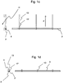
- FIGS. 1a to 1d show schematically the operation of a first embodiment of the claimed winding device.
- the winding device 1 comprises a cover element 3 with an upper longitudinal edge 5 and a lower longitudinal edge 7.
- the cover element 3 is designed with respect to its length such that it is in the not rolled up on a deflecting element 9, the wall opening 11 can partially or optionally completely cover.
- the longitudinal edges 5 and 7 of the cover 3 may have additional reinforcements.
- the lower longitudinal edge 7 is fixedly connected to the deflecting element 9.
- the deflecting element 9 is suspended between the cable sections 13 and 13 'and is in the rope bend of the oppositely moving sections 13 and 13' up or unrolled. At the lower deflection point of the cable sections, a bend is formed, so that the cable 13 causes the rotational movement of the deflecting element 9.
- the rope 13 or 13 ' is guided parallel to a vertical axis Z. The direction of movement of the cable 13 during the downward movement is in FIG. 1a indicated by the arrow Y direction.
- the rope 13 or 13 ' is connected at a connection point 17 with the upper longitudinal edge 5 of the cover 3.
- FIG. 1a shows open position in which the wall opening is covered by the completely rolled cover 3, in a basic position accordingly Fig. 1 c.
- Fig. 1 c is the cover 3 in the rolled-up state, so that the wall opening is open and thus an air exchange between the interior of the building can be done with the outside air.
- FIG. 1b the winding device 1 is only partially open.
- the cover 3 is already partly rolled up on the deflection element 9.
- the wall opening 11 is in FIG. 1b only covered in the lower part of the cover 3.
- the upper longitudinal edge 5 is parallel to a horizontal axis (not shown) in the in FIG. 1 a guided by the arrow Y direction of movement out.
- the rotational speed of the deflecting element 9 remains during the movement of the upper longitudinal edge 5 in the in FIG. 1a indicated by the arrow Y movement direction is not necessarily constant, but is possibly slower by the increasing diameter of the deflecting element 9 with the cover 3 wound thereon.
- the inventive design is an automatic adjustment of the rotational speed of the deflecting element 9 to the diameter of the deflecting element 9 with cover 3, even if this changed, for example, by dirt, wrinkles or cold.
- Figure 1c shows the cover 3 in the fully rolled state on the deflector 9.
- the wall opening 11 is completely exposed.
- To transfer shown position the direction of movement of the ropes is not maintained, but the draining rope is the lifting rope.
- the deflecting element is raised with the cover in the rolled up state. It is conceivable that the transfer to the in Fig. 1d shown position can also be done from another position of the winding device, for example. From a half-opened position accordingly Fig. 1b ,
- FIGS. 2a to 2d show schematically the operation of another embodiment of the claimed winding device 1 with a shaft 19th
- FIG. 2a the structure of the embodiment will be apparent.
- the shaft is rotated by a motor 21.
- Both free ends 23 and 25 are fixedly connected to the shaft 19.
- working rope 27 is arranged on the shaft 19, so that by unwinding of the working rope 27 of the shaft 19, a downward movement of the cable 13 can be brought about.
- Analogous to the embodiment according to the FIGS. 1a to 1d If the cable 13 or 13 'at a junction 17 with the upper longitudinal edge 5 of the cover 3 is connected.
- the winding device 1 is only partially open.
- the shaft 19 is in the rotating state, so that the working rope 27 is unwound from the region of the first free end 23, is continued by the deflecting element 9 and is arranged thereon in the region of the second free end 25.
- the rotational direction of the shaft 19 can be changed by the motor 21, so that the working rope 27 can be arranged again in the region of the first free end 23.
- With the unwinding of the working rope 27 is a movement of the upper longitudinal edge 5 in the in FIG. 1a indicated arrow Y accompanied, whereby the cover 3 is rolled up on the deflection element 9.
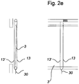
- FIG. 2e shows an embodiment of the invention with an additional guide of the rope 13, 13 '.
- the cable 13, 13 ' is stabilized by a tensioning device 30 at the lowest point of the cable 13, 13'.
- the rope 13, 13 ' in addition to its previous tasks as stabilizing the winding device or the cover 3 when, for example, wind or suction loads occur.
- FIG. 2f schematically shows the operation of another embodiment of the claimed winding device 1 with shaft 19.
- the shaft is rotated by a motor 21.
- Both free ends 23 and 25 are fixedly connected to the shaft 19.
- the so-called work rope 27 is arranged on the shaft 19, so that by unwinding of the working rope 27 of the shaft 19, a downward movement of the cable 13 can be brought about.
- Figure 2g shows the inventive embodiment of the winding device according to the FIGS. 2e to 2f with an additional guidance of the rope 13, 13 'by a tensioning device 30' in the cable bend.
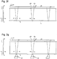
- FIGS. 3a to 3d schematically show the operation of another embodiment of the claimed winding device 1 with cable.
- the winding and unwinding of the cover 3 on the deflection element 9 and the lifting and lowering of the deflection element 9 are controlled in the embodiment shown via cable.
- the cable comprises a plurality of pulleys 28 and a cable 29.
- the rope 13, or 13 ' are guided over the pulleys 28. In the embodiment shown, that part of the cable 13 which performs the downward movement, rotated by 270 °, by the left of the two pulleys 28, counterclockwise and continued.
- the part of the cable 13 ', which performs the upward movement is also continued in the embodiment by the left of the two pulleys 28. However, the continuation takes place in the opposite direction to the continuation of the rope 13.
- the change from the discharging rope to the lifting rope is effected, which for the change of the Fig. 3c in the Fig. 3d is required.
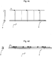
- FIGS. 4a to 4d show schematically the operation of another embodiment of the claimed winding device 1 with first cables 13 and 13 'and second cables 31st
- second ropes 31 are provided in which a free end is fixedly connected to the shaft 19 and the second free end is fixedly connected to the upper longitudinal edge 5 of the cover 3.
- connection point 17 such as in the embodiment of FIGS. 1a to 1d pointed out, be waived.
- FIGS. 4b to 4c becomes analogous to the Figures 1b . 1c and 2 B . 2c and 3b, 3c show the successive process during the transfer of the winding device 1 from an open position to a basic position.
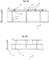
- FIGS. 5a to 5d schematically show the operation of another embodiment of the claimed winding device 1 with first cables 13 and 13 'and second cables 31.
- a free end 23 of the first cable 13' is fixedly connected to the shaft 19.
- the second free end 25 of the first cable 13 is fixedly connected to the upper longitudinal edge 5.
- a free end of the second cable 31 is fixedly connected to the shaft 19.
- the second free end of the second cable 31 is fixedly connected to the upper longitudinal edge 5.
- FIGS. 5b to 5c the successive process during the transfer of the winding device 1 from an open position to a basic position is shown analogously to the previous figures with the numbers "b" and "c".
- the deflecting element 9 does not necessarily mean a rigid part or even a separate part of the winding device 1 according to the invention.
- the deflecting element 9 can, for example, also be formed by the lower fabric seam or by the lower fabric edge, which rotates through the articulation of the windable cables with these in a defined direction and in a loose winding, thereby winding or unwinding.
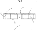
- FIG. 6 shows the use of a winding device 1 according to the invention for covering an interrupted opening.
- the winding device 1 is interrupted by a door or a similar interruption 50 in the region of the cover element 3.
- the function can be analogous to that of FIGS. 1 and 2 despite the interruption 50 be accomplished by means of a drive unit.
- FIGS. 7a to 7d illustrate schematically various embodiments of the winding device 1 according to the invention with optimized pitch lengths.
- FIGS. 7a and 7b illustrated embodiments are both ends of the rope ropes 13, 13 'on the lifting / lowering device, for example on a shaft 19 (FIG. Fig. 7b ) or on a cable 29 ( Fig. 7a ) attached.
- the optimal rope length of the rope 13, 13 'to reach the functions corresponds approximately to the sum three times the height H of the cover 3 and twice the distance M between the upper longitudinal edge 5 of the rolled cover 3 and the lifting / lowering device.
- Fig. 7c It is shown that one end of the rope is attached to the lifting / lowering device in the form of a shaft 19 and the other end of the rope at the upper longitudinal edge 5 of the cover 3.
- an optimized cable length which is approximately twice the height H of the cover 3 plus once the distance M between the upper longitudinal edge 5 of the cover 3 in the unrolled state and the lifting / lowering device, sufficient.
- the embodiment according to FIG. 7d represents the optimized rope length of a second rope 31.
- the cable 31 in this case does not comprise the cover element 3, but is guided directly to the upper longitudinal edge 5.
- the optimal cable length of the rope 31 is approximately the sum of once the height H of the cover 5 and once the distance M between the upper longitudinal edge 5 of the cover 3 in the unrolled state and the lifting / lowering device.
Landscapes
- Engineering & Computer Science (AREA)
- Structural Engineering (AREA)
- Architecture (AREA)
- Civil Engineering (AREA)
- Operating, Guiding And Securing Of Roll- Type Closing Members (AREA)
- Blinds (AREA)
- Winding Filamentary Materials (AREA)
- Storage Of Web-Like Or Filamentary Materials (AREA)
- Working Measures On Existing Buildindgs (AREA)
- Burglar Alarm Systems (AREA)
Claims (12)
- Dispositif d'enroulement (1) pour l'occlusion d'ouvertures murales (11) ou de fenêtres, avec un élément de recouvrement (3) enroulable, un élément de renvoi (9) et au moins un dispositif de levée et de descente,- l'élément de recouvrement (3) présentant un bord longitudinal supérieur (5) et une bord longitudinal inférieur (7),- le bord longitudinal inférieur (7) de l'élément de recouvrement (3) étant relié à l'élément de renvoi (9) ou formant l'élément de renvoi (9), de sorte que l'élément de recouvrement (3) peut être enroulé respectivement sur l'élément de renvoi (9) ou sur le bord longitudinal inférieur (7) de l'élément de recouvrement (3) par une rotation respectivement de l'élément de renvoi (9) ou du bord longitudinal inférieur (7) autour d'un axe disposé horizontalement,- le dispositif d'enroulement (1) comprenant au moins un cordon (13, 13') dont au moins une extrémité libre (23, 25) est reliée au dispositif de levée et de descente, le cordon (13, 13') étant disposé de manière à envelopper l'élément de recouvrement (3) de telle sorte que respectivement l'élément de renvoi (9) ou le bord longitudinal inférieur (7) de l'élément de recouvrement (3) soit guidé dans l'arrondi du cordon,- le dispositif de levée et de descente étant un arbre ou un câble de traction, et l'élément de renvoi (9) ou le bord longitudinal inférieur (7) de l'élément de recouvrement (3) respectivement étant d'une part mis en rotation par une rotation de l'arbre ou un déplacement horizontal du câble de traction par le mouvement de l'au moins un cordon (13, 13', 31) dans deux directions de mouvement opposées l'une à l'autre, et d'autre part le bord longitudinal supérieur étant simultanément levé et/ou descendu par abaissement et/ou soulèvement d'au moins un cordon (13, 13', 31).
- Dispositif d'enroulement selon la revendication 1, dans lequel il est prévu au moins un premier cordon (13, 13') et au moins un deuxième cordon (31), le premier cordon (13, 13') guidant respectivement l'élément de renvoi (9) ou le bord longitudinal inférieur (7) de l'élément de recouvrement (3) dans deux directions de mouvement opposées l'une à l'autre et- le premier cordon (13, 13') étant prévu pour enrouler respectivement l'élément de recouvrement (3) ou le bord longitudinal inférieur (7) de l'élément de recouvrement (3), ou pour enrouler respectivement l'élément de recouvrement (3) ou le bord longitudinal inférieur (7), et soulever ou abaisser l'élément de recouvrement (3) enroulé, et- le deuxième cordon (31) étant prévu pour soulever et abaisser le bord longitudinal supérieur (5) de l'élément de recouvrement (3).
- Dispositif d'enroulement selon la revendication 2, dans lequel- le premier cordon (13, 13') est relié par les deux extrémités libres (23, 25) au dispositif de levée et de descente, et- le deuxième cordon (31) est relié par sa première extrémité libre au dispositif de levée et de descente et par sa deuxième extrémité libre au bord longitudinal supérieur (5) de l'élément de recouvrement (3).
- Dispositif d'enroulement selon la revendication 2, dans lequel- le premier cordon (13, 13') est disposé avec sa première extrémité libre (23) sur le dispositif de levée et de descente et avec sa deuxième extrémité libre (25) sur le bord longitudinal supérieur (5) de l'élément de recouvrement (3), et- le deuxième cordon (31) est disposé avec sa première extrémité libre sur le dispositif de levée et de descente et avec sa deuxième extrémité libre sur le bord longitudinal supérieur (5) de l'élément de recouvrement (3).
- Dispositif d'enroulement selon l'une des revendications précédentes, dans lequel l'élément de recouvrement (3) peut être enroulé respectivement sur l'élément de renvoi (9) ou sur le bord longitudinal inférieur (7) de l'élément de recouvrement (3) par rotation de celui-ci et peut être soulevé en soulevant l'au moins un premier cordon (13, 13') et/ou l'au moins un deuxième cordon (31).
- Dispositif d'enroulement selon l'une des revendications précédentes, dans lequel l'au moins un cordon (13, 13') est guidé et/ou fixé par un dispositif de tension (30, 30').
- Dispositif d'enroulement selon l'une des revendications précédentes, dans lequel l'au moins un premier cordon (13, 13') présente une longueur qui correspond approximativement à la somme de trois fois la hauteur (H) de l'élément de recouvrement (3) plus deux fois la distance (M) entre le bord longitudinal supérieur (5) de l'élément de recouvrement (3) complètement déroulé et le dispositif de levée et de descente, ou approximativement à la somme de deux fois la hauteur de l'élément de recouvrement (3) plus une fois la distance (M) entre le bord longitudinal supérieur (5) de l'élément de recouvrement (3) complètement déroulé et le dispositif de levée et de descente.
- Dispositif d'enroulement selon l'une des revendications 2 à 7, dans lequel l'au moins un deuxième cordon (31) présente une longueur qui correspond approximativement à la somme d'une fois la hauteur (H) de l'élément de recouvrement (3) plus une fois la distance (M) entre le bord longitudinal supérieur (5) de l'élément de recouvrement (3) complètement déroulé et le dispositif de levée et de descente.
- Dispositif d'enroulement selon l'une des revendications précédentes, dans lequel, lorsque l'élément de recouvrement (3) est complètement déroulé, la longueur du cordon de travail (27) du cordon (13, 31) correspond approximativement à la hauteur (H) de l'élément de recouvrement (3).
- Dispositif d'enroulement selon l'une des revendications précédentes, dans lequel le cordon (13, 13') est relié au bord longitudinal supérieur (5) de l'élément de recouvrement (3).
- Procédé pour enrouler un dispositif d'enroulement (1) pour l'occlusion d'ouvertures murales (11) ou de fenêtres avec un élément de recouvrement (3) enroulable, un élément de renvoi (9) et au moins un dispositif de levée et de descente, l'élément de recouvrement (3) présentant un bord longitudinal supérieur (5) et un bord longitudinal inférieur (7), et le bord longitudinal inférieur (7) de l'élément de recouvrement (3) étant relié à l'élément de renvoi (9) ou formant l'élément de renvoi (9), et le dispositif d'enroulement (1) comprenant au moins un cordon (13, 13') dont au moins une extrémité libre (23, 25) est reliée au dispositif de levée et de descente, le cordon (13, 13') étant disposé de telle sorte qu'il enveloppe l'élément de recouvrement (3) de telle sorte que respectivement l'élément de renvoi (9) ou le bord longitudinal inférieur (7) soit guidé dans l'arrondi du cordon, le dispositif de levée et de descente étant un arbre ou un câble de traction, et l'élément de renvoi (9) ou le bord longitudinal inférieur (7) respectivement étant d'une part mis en rotation par une rotation de l'arbre ou un déplacement horizontal du câble de traction par le mouvement de l'au moins un cordon (13, 13', 31) dans deux directions de mouvement opposées l'une à l'autre, l'élément de recouvrement (3) étant enroulé respectivement sur l'élément de renvoi (9) ou sur le bord longitudinal inférieur (7) par la rotation respectivement de l'élément de renvoi (9) ou du bord longitudinal inférieur (7) autour d'un axe disposé horizontalement, et d'autre part le bord longitudinal supérieur ( 5 ) étant simultanément levé et/ou descendu par abaissement et/ou soulèvement d'au moins un cordon (13, 13', 31).
- Procédé selon la revendication 11, dans lequel le dispositif d'enroulement comprend un deuxième cordon (31) qui est disposé par sa première extrémité libre sur le dispositif de levée et de descente et par sa deuxième extrémité libre sur le bord longitudinal supérieur (5) de l'élément de recouvrement (3), et dans lequel le cordon d'abaissement (13, 31) devient un cordon de soulèvement pour l'élément de recouvrement (3) enroulé par respectivement un déroulement ou un abaissement complet et par une rotation supplémentaire de l'arbre ou par une traction supplémentaire du câble de traction.
Applications Claiming Priority (2)
| Application Number | Priority Date | Filing Date | Title |
|---|---|---|---|
| DE202009005007U DE202009005007U1 (de) | 2009-07-09 | 2009-07-09 | Wickelvorrichtung zum Bedecken von Wandöffnungen oder Fenstern |
| PCT/EP2010/004082 WO2011003576A2 (fr) | 2009-07-09 | 2010-07-06 | Dispositif à enroulement pour l'occlusion d'ouvertures pratiquées dans des murs ou de fenêtres |
Publications (2)
| Publication Number | Publication Date |
|---|---|
| EP2452034A2 EP2452034A2 (fr) | 2012-05-16 |
| EP2452034B1 true EP2452034B1 (fr) | 2018-03-14 |
Family
ID=43304817
Family Applications (1)
| Application Number | Title | Priority Date | Filing Date |
|---|---|---|---|
| EP10743015.9A Not-in-force EP2452034B1 (fr) | 2009-07-09 | 2010-07-06 | Dispositif à enroulement pour l'occlusion d'ouvertures pratiquées dans des murs ou de fenêtres |
Country Status (10)
| Country | Link |
|---|---|
| US (1) | US8820387B2 (fr) |
| EP (1) | EP2452034B1 (fr) |
| JP (1) | JP5852957B2 (fr) |
| KR (1) | KR101762976B1 (fr) |
| CN (1) | CN102472080B (fr) |
| CA (1) | CA2767466C (fr) |
| DE (1) | DE202009005007U1 (fr) |
| DK (1) | DK2452034T3 (fr) |
| EA (1) | EA026010B1 (fr) |
| WO (1) | WO2011003576A2 (fr) |
Families Citing this family (8)
| Publication number | Priority date | Publication date | Assignee | Title |
|---|---|---|---|---|
| DE202009005007U1 (de) * | 2009-07-09 | 2010-12-16 | Zettl, Horst | Wickelvorrichtung zum Bedecken von Wandöffnungen oder Fenstern |
| IL220779A (en) * | 2012-07-05 | 2016-08-31 | Holis Metal Ind Ltd | Two-stage curtain |
| DE202014105368U1 (de) * | 2014-11-10 | 2014-12-01 | Lock Antriebstechnik Gmbh | Wickelvorrichtung zur Abdeckung von Gebäudeöffnungen |
| CN105545192B (zh) * | 2015-01-30 | 2017-04-19 | 福建固美金属有限公司 | 一种智能双向卷帘式窗户的开关方法 |
| US11534983B2 (en) | 2016-01-14 | 2022-12-27 | Shady Lane Curtains, Llc | Method of making a barn curtain with joined panels |
| US11134652B2 (en) | 2016-01-14 | 2021-10-05 | Shady Lane Curtains, Llc | Retractable curtain for livestock structures |
| KR102092614B1 (ko) | 2018-10-22 | 2020-03-24 | 휴켐스주식회사 | 1,4-디이오도벤젠을 이용한 4,4'-옥시디아닐린의 제조방법 |
| CN113885291B (zh) * | 2021-10-23 | 2022-05-13 | 江苏舜合物联网科技有限公司 | 一种弹簧实现幕布升降收集机构 |
Citations (2)
| Publication number | Priority date | Publication date | Assignee | Title |
|---|---|---|---|---|
| US75037A (en) * | 1868-03-03 | Improved window-shade | ||
| US119983A (en) * | 1871-10-17 | Improvement in curtain-fixtures |
Family Cites Families (21)
| Publication number | Priority date | Publication date | Assignee | Title |
|---|---|---|---|---|
| US112814A (en) * | 1871-03-21 | Improvement in curtain-fixtures | ||
| US108752A (en) * | 1870-11-01 | Improvement in curtain-fixtures | ||
| US257826A (en) * | 1882-05-09 | Curtain-fixture | ||
| US1181120A (en) * | 1915-07-06 | 1916-05-02 | Walter C Douthitt | Blind or shade. |
| US1225060A (en) * | 1916-01-28 | 1917-05-08 | Clyde W Warren | Curtain-anchoring device. |
| US1464412A (en) * | 1921-05-16 | 1923-08-07 | Dillon Frank | Shade roller |
| US1473517A (en) * | 1922-02-06 | 1923-11-06 | Wilbert M Richards | Roller-curtain guiding and locking device |
| US1870920A (en) * | 1929-09-16 | 1932-08-09 | Thomas E Mcnulty | Curtain guide |
| US2582276A (en) * | 1949-05-16 | 1952-01-15 | Frank M Powers | Porch shade |
| FR2563860A1 (fr) * | 1984-05-03 | 1985-11-08 | Farnier & Penin | Store motorise a deroulement et a enroulement commandes positivement. |
| JPH01162587U (fr) * | 1988-04-28 | 1989-11-13 | ||
| US5819835A (en) * | 1995-09-20 | 1998-10-13 | Draper Shade & Screen Co., Inc. | Roll-up divider |
| US5785105A (en) * | 1995-11-13 | 1998-07-28 | Crider; Grant W. | Sealable curtain |
| DE29815953U1 (de) | 1998-05-28 | 1998-11-19 | Arntjen, Gerd, 26180 Rastede | Lüftungsvorrichtung zur Anordnung in einem Wandflächenbereich eines Stallgebäudes |
| US6138739A (en) * | 1999-01-15 | 2000-10-31 | Grant W. Crider | Portal covering |
| DE20117865U1 (de) | 2001-11-06 | 2002-02-28 | AGROTEL GmbH, 94152 Neuhaus | Verschlussvorrichtung |
| JP3850301B2 (ja) * | 2002-01-24 | 2006-11-29 | 株式会社ニチベイ | ロールスクリーン |
| DE20214076U1 (de) | 2002-09-10 | 2003-05-08 | Bvba Vervaeke, Ruiselede | Vorrichtung zum Abschirmen eines Raumes |
| US6860312B2 (en) * | 2002-09-27 | 2005-03-01 | Ren Judkins | Roll-up shade with cord capture |
| GB2431190B (en) * | 2005-10-13 | 2010-02-24 | John Benjamin Slater | Adjustable screen |
| DE202009005007U1 (de) * | 2009-07-09 | 2010-12-16 | Zettl, Horst | Wickelvorrichtung zum Bedecken von Wandöffnungen oder Fenstern |
-
2009
- 2009-07-09 DE DE202009005007U patent/DE202009005007U1/de not_active Expired - Lifetime
-
2010
- 2010-07-06 DK DK10743015.9T patent/DK2452034T3/en active
- 2010-07-06 JP JP2012518810A patent/JP5852957B2/ja not_active Expired - Fee Related
- 2010-07-06 US US13/381,782 patent/US8820387B2/en active Active
- 2010-07-06 CN CN201080030772.XA patent/CN102472080B/zh not_active Expired - Fee Related
- 2010-07-06 EP EP10743015.9A patent/EP2452034B1/fr not_active Not-in-force
- 2010-07-06 KR KR1020127003405A patent/KR101762976B1/ko active IP Right Grant
- 2010-07-06 EA EA201200099A patent/EA026010B1/ru not_active IP Right Cessation
- 2010-07-06 WO PCT/EP2010/004082 patent/WO2011003576A2/fr active Application Filing
- 2010-07-06 CA CA2767466A patent/CA2767466C/fr active Active
Patent Citations (2)
| Publication number | Priority date | Publication date | Assignee | Title |
|---|---|---|---|---|
| US75037A (en) * | 1868-03-03 | Improved window-shade | ||
| US119983A (en) * | 1871-10-17 | Improvement in curtain-fixtures |
Also Published As
| Publication number | Publication date |
|---|---|
| JP5852957B2 (ja) | 2016-02-03 |
| WO2011003576A3 (fr) | 2011-11-24 |
| WO2011003576A2 (fr) | 2011-01-13 |
| US20120138243A1 (en) | 2012-06-07 |
| CN102472080A (zh) | 2012-05-23 |
| EP2452034A2 (fr) | 2012-05-16 |
| CA2767466A1 (fr) | 2011-01-13 |
| US8820387B2 (en) | 2014-09-02 |
| EA201200099A1 (ru) | 2012-08-30 |
| KR101762976B1 (ko) | 2017-07-28 |
| CA2767466C (fr) | 2014-01-21 |
| JP2012532260A (ja) | 2012-12-13 |
| DE202009005007U1 (de) | 2010-12-16 |
| EA026010B1 (ru) | 2017-02-28 |
| KR20120039706A (ko) | 2012-04-25 |
| CN102472080B (zh) | 2015-12-09 |
| DK2452034T3 (en) | 2018-06-18 |
Similar Documents
| Publication | Publication Date | Title |
|---|---|---|
| EP2452034B1 (fr) | Dispositif à enroulement pour l'occlusion d'ouvertures pratiquées dans des murs ou de fenêtres | |
| WO1997021014A1 (fr) | Tente-parasol reglable | |
| EP0082302B1 (fr) | Dispositif de protection contre le rayonnement solaire et/ou les intempéries | |
| EP0982466B1 (fr) | Store à rouleau | |
| EP2817471B1 (fr) | Dispositif d'enroulement et déroulement d'une bande de matière sur et à partir d'un arbre | |
| AT399370B (de) | Jalousie | |
| DE29815953U1 (de) | Lüftungsvorrichtung zur Anordnung in einem Wandflächenbereich eines Stallgebäudes | |
| EP2730738B1 (fr) | Dispositif à enroulement destiné à recouvrir des ouvertures dans des sections de mur | |
| EP1908915B1 (fr) | Procédé de montage pour une porte à enroulement | |
| DE69103157T2 (de) | Vorhangvorrichtung. | |
| DE20109240U1 (de) | Raffvorhang mit einer einzigen Zugschnur | |
| DE29916738U1 (de) | Rolloeinrichtung | |
| DE29824480U1 (de) | Wickeljalousie | |
| DE3717878C2 (fr) | ||
| EP1388637B1 (fr) | Rouleau | |
| DE10126812C2 (de) | Raffvorhang mit auf einer Welle befestigten Aufwickelelementen | |
| DE102009013325A1 (de) | Vertikal sowie horizontal verbaubares Rollosystem, insbesondere Insektenschutzgitter-Rollosystem, mit geringer Bautiefe | |
| DE10063454B4 (de) | Vorrichtung zum Verschließen und/oder Beschatten eines Öffnungsquerschnitts bzw. einer Fläche | |
| DE19707408A1 (de) | Abdeckvorrichtung, insbesondere Markise | |
| DE202005007354U1 (de) | Beschattungsvorrichtung mit aufwickelbarem bahnförmigen Beschattungselement | |
| DE10126813C2 (de) | Raffvorhang mit einer einzigen Zugschnur | |
| DE20005567U1 (de) | Sonnenschutzanlage mit gegen Ausfall gesichertem Antrieb | |
| EP4253711A1 (fr) | Dispositif d'enroulement destiné à être utilisé sur un dispositif de protection solaire | |
| DE202015100293U1 (de) | Vorrichtung zum Schutz einer Gebäudeöffnung | |
| DE29511378U1 (de) | Vorhang, insbesondere Falt- oder Lamellenjalousie oder Rollo |
Legal Events
| Date | Code | Title | Description |
|---|---|---|---|
| PUAI | Public reference made under article 153(3) epc to a published international application that has entered the european phase |
Free format text: ORIGINAL CODE: 0009012 |
|
| 17P | Request for examination filed |
Effective date: 20120110 |
|
| AK | Designated contracting states |
Kind code of ref document: A2 Designated state(s): AL AT BE BG CH CY CZ DE DK EE ES FI FR GB GR HR HU IE IS IT LI LT LU LV MC MK MT NL NO PL PT RO SE SI SK SM TR |
|
| DAX | Request for extension of the european patent (deleted) | ||
| RAP1 | Party data changed (applicant data changed or rights of an application transferred) |
Owner name: LOCK ANTRIEBSTECHNIK GMBH |
|
| RIN1 | Information on inventor provided before grant (corrected) |
Inventor name: ZETTL, HORST |
|
| 17Q | First examination report despatched |
Effective date: 20150804 |
|
| GRAP | Despatch of communication of intention to grant a patent |
Free format text: ORIGINAL CODE: EPIDOSNIGR1 |
|
| INTG | Intention to grant announced |
Effective date: 20171129 |
|
| GRAS | Grant fee paid |
Free format text: ORIGINAL CODE: EPIDOSNIGR3 |
|
| GRAA | (expected) grant |
Free format text: ORIGINAL CODE: 0009210 |
|
| STAA | Information on the status of an ep patent application or granted ep patent |
Free format text: STATUS: THE PATENT HAS BEEN GRANTED |
|
| AK | Designated contracting states |
Kind code of ref document: B1 Designated state(s): AL AT BE BG CH CY CZ DE DK EE ES FI FR GB GR HR HU IE IS IT LI LT LU LV MC MK MT NL NO PL PT RO SE SI SK SM TR |
|
| REG | Reference to a national code |
Ref country code: GB Ref legal event code: FG4D Free format text: NOT ENGLISH |
|
| REG | Reference to a national code |
Ref country code: AT Ref legal event code: REF Ref document number: 979063 Country of ref document: AT Kind code of ref document: T Effective date: 20180315 Ref country code: CH Ref legal event code: EP |
|
| REG | Reference to a national code |
Ref country code: IE Ref legal event code: FG4D Free format text: LANGUAGE OF EP DOCUMENT: GERMAN |
|
| REG | Reference to a national code |
Ref country code: DE Ref legal event code: R096 Ref document number: 502010014758 Country of ref document: DE |
|
| REG | Reference to a national code |
Ref country code: FR Ref legal event code: PLFP Year of fee payment: 9 |
|
| REG | Reference to a national code |
Ref country code: CH Ref legal event code: NV Representative=s name: KELLER AND PARTNER PATENTANWAELTE AG, CH |
|
| REG | Reference to a national code |
Ref country code: DK Ref legal event code: T3 Effective date: 20180613 |
|
| REG | Reference to a national code |
Ref country code: NL Ref legal event code: FP |
|
| REG | Reference to a national code |
Ref country code: LT Ref legal event code: MG4D |
|
| PG25 | Lapsed in a contracting state [announced via postgrant information from national office to epo] |
Ref country code: ES Free format text: LAPSE BECAUSE OF FAILURE TO SUBMIT A TRANSLATION OF THE DESCRIPTION OR TO PAY THE FEE WITHIN THE PRESCRIBED TIME-LIMIT Effective date: 20180314 Ref country code: FI Free format text: LAPSE BECAUSE OF FAILURE TO SUBMIT A TRANSLATION OF THE DESCRIPTION OR TO PAY THE FEE WITHIN THE PRESCRIBED TIME-LIMIT Effective date: 20180314 Ref country code: NO Free format text: LAPSE BECAUSE OF FAILURE TO SUBMIT A TRANSLATION OF THE DESCRIPTION OR TO PAY THE FEE WITHIN THE PRESCRIBED TIME-LIMIT Effective date: 20180614 Ref country code: HR Free format text: LAPSE BECAUSE OF FAILURE TO SUBMIT A TRANSLATION OF THE DESCRIPTION OR TO PAY THE FEE WITHIN THE PRESCRIBED TIME-LIMIT Effective date: 20180314 Ref country code: CY Free format text: LAPSE BECAUSE OF FAILURE TO SUBMIT A TRANSLATION OF THE DESCRIPTION OR TO PAY THE FEE WITHIN THE PRESCRIBED TIME-LIMIT Effective date: 20180314 Ref country code: LT Free format text: LAPSE BECAUSE OF FAILURE TO SUBMIT A TRANSLATION OF THE DESCRIPTION OR TO PAY THE FEE WITHIN THE PRESCRIBED TIME-LIMIT Effective date: 20180314 |
|
| PGFP | Annual fee paid to national office [announced via postgrant information from national office to epo] |
Ref country code: DK Payment date: 20180611 Year of fee payment: 9 Ref country code: CH Payment date: 20180621 Year of fee payment: 9 |
|
| PG25 | Lapsed in a contracting state [announced via postgrant information from national office to epo] |
Ref country code: SE Free format text: LAPSE BECAUSE OF FAILURE TO SUBMIT A TRANSLATION OF THE DESCRIPTION OR TO PAY THE FEE WITHIN THE PRESCRIBED TIME-LIMIT Effective date: 20180314 Ref country code: LV Free format text: LAPSE BECAUSE OF FAILURE TO SUBMIT A TRANSLATION OF THE DESCRIPTION OR TO PAY THE FEE WITHIN THE PRESCRIBED TIME-LIMIT Effective date: 20180314 Ref country code: BG Free format text: LAPSE BECAUSE OF FAILURE TO SUBMIT A TRANSLATION OF THE DESCRIPTION OR TO PAY THE FEE WITHIN THE PRESCRIBED TIME-LIMIT Effective date: 20180614 Ref country code: GR Free format text: LAPSE BECAUSE OF FAILURE TO SUBMIT A TRANSLATION OF THE DESCRIPTION OR TO PAY THE FEE WITHIN THE PRESCRIBED TIME-LIMIT Effective date: 20180615 |
|
| PG25 | Lapsed in a contracting state [announced via postgrant information from national office to epo] |
Ref country code: MT Free format text: LAPSE BECAUSE OF FAILURE TO SUBMIT A TRANSLATION OF THE DESCRIPTION OR TO PAY THE FEE WITHIN THE PRESCRIBED TIME-LIMIT Effective date: 20180314 |
|
| PG25 | Lapsed in a contracting state [announced via postgrant information from national office to epo] |
Ref country code: PL Free format text: LAPSE BECAUSE OF FAILURE TO SUBMIT A TRANSLATION OF THE DESCRIPTION OR TO PAY THE FEE WITHIN THE PRESCRIBED TIME-LIMIT Effective date: 20180314 Ref country code: RO Free format text: LAPSE BECAUSE OF FAILURE TO SUBMIT A TRANSLATION OF THE DESCRIPTION OR TO PAY THE FEE WITHIN THE PRESCRIBED TIME-LIMIT Effective date: 20180314 Ref country code: EE Free format text: LAPSE BECAUSE OF FAILURE TO SUBMIT A TRANSLATION OF THE DESCRIPTION OR TO PAY THE FEE WITHIN THE PRESCRIBED TIME-LIMIT Effective date: 20180314 Ref country code: IT Free format text: LAPSE BECAUSE OF FAILURE TO SUBMIT A TRANSLATION OF THE DESCRIPTION OR TO PAY THE FEE WITHIN THE PRESCRIBED TIME-LIMIT Effective date: 20180314 Ref country code: AL Free format text: LAPSE BECAUSE OF FAILURE TO SUBMIT A TRANSLATION OF THE DESCRIPTION OR TO PAY THE FEE WITHIN THE PRESCRIBED TIME-LIMIT Effective date: 20180314 |
|
| PGFP | Annual fee paid to national office [announced via postgrant information from national office to epo] |
Ref country code: GB Payment date: 20180612 Year of fee payment: 9 |
|
| PG25 | Lapsed in a contracting state [announced via postgrant information from national office to epo] |
Ref country code: SM Free format text: LAPSE BECAUSE OF FAILURE TO SUBMIT A TRANSLATION OF THE DESCRIPTION OR TO PAY THE FEE WITHIN THE PRESCRIBED TIME-LIMIT Effective date: 20180314 Ref country code: CZ Free format text: LAPSE BECAUSE OF FAILURE TO SUBMIT A TRANSLATION OF THE DESCRIPTION OR TO PAY THE FEE WITHIN THE PRESCRIBED TIME-LIMIT Effective date: 20180314 Ref country code: SK Free format text: LAPSE BECAUSE OF FAILURE TO SUBMIT A TRANSLATION OF THE DESCRIPTION OR TO PAY THE FEE WITHIN THE PRESCRIBED TIME-LIMIT Effective date: 20180314 |
|
| PGFP | Annual fee paid to national office [announced via postgrant information from national office to epo] |
Ref country code: AT Payment date: 20180710 Year of fee payment: 9 |
|
| REG | Reference to a national code |
Ref country code: DE Ref legal event code: R097 Ref document number: 502010014758 Country of ref document: DE |
|
| PG25 | Lapsed in a contracting state [announced via postgrant information from national office to epo] |
Ref country code: PT Free format text: LAPSE BECAUSE OF FAILURE TO SUBMIT A TRANSLATION OF THE DESCRIPTION OR TO PAY THE FEE WITHIN THE PRESCRIBED TIME-LIMIT Effective date: 20180716 |
|
| PLBE | No opposition filed within time limit |
Free format text: ORIGINAL CODE: 0009261 |
|
| STAA | Information on the status of an ep patent application or granted ep patent |
Free format text: STATUS: NO OPPOSITION FILED WITHIN TIME LIMIT |
|
| 26N | No opposition filed |
Effective date: 20181217 |
|
| PG25 | Lapsed in a contracting state [announced via postgrant information from national office to epo] |
Ref country code: SI Free format text: LAPSE BECAUSE OF FAILURE TO SUBMIT A TRANSLATION OF THE DESCRIPTION OR TO PAY THE FEE WITHIN THE PRESCRIBED TIME-LIMIT Effective date: 20180314 |
|
| PG25 | Lapsed in a contracting state [announced via postgrant information from national office to epo] |
Ref country code: LU Free format text: LAPSE BECAUSE OF NON-PAYMENT OF DUE FEES Effective date: 20180706 Ref country code: MC Free format text: LAPSE BECAUSE OF FAILURE TO SUBMIT A TRANSLATION OF THE DESCRIPTION OR TO PAY THE FEE WITHIN THE PRESCRIBED TIME-LIMIT Effective date: 20180314 |
|
| REG | Reference to a national code |
Ref country code: BE Ref legal event code: MM Effective date: 20180731 |
|
| REG | Reference to a national code |
Ref country code: IE Ref legal event code: MM4A |
|
| PG25 | Lapsed in a contracting state [announced via postgrant information from national office to epo] |
Ref country code: IE Free format text: LAPSE BECAUSE OF NON-PAYMENT OF DUE FEES Effective date: 20180706 |
|
| PG25 | Lapsed in a contracting state [announced via postgrant information from national office to epo] |
Ref country code: BE Free format text: LAPSE BECAUSE OF NON-PAYMENT OF DUE FEES Effective date: 20180731 |
|
| REG | Reference to a national code |
Ref country code: DK Ref legal event code: EBP Effective date: 20190731 |
|
| REG | Reference to a national code |
Ref country code: CH Ref legal event code: PL |
|
| REG | Reference to a national code |
Ref country code: AT Ref legal event code: MM01 Ref document number: 979063 Country of ref document: AT Kind code of ref document: T Effective date: 20190706 |
|
| GBPC | Gb: european patent ceased through non-payment of renewal fee |
Effective date: 20190706 |
|
| PG25 | Lapsed in a contracting state [announced via postgrant information from national office to epo] |
Ref country code: TR Free format text: LAPSE BECAUSE OF FAILURE TO SUBMIT A TRANSLATION OF THE DESCRIPTION OR TO PAY THE FEE WITHIN THE PRESCRIBED TIME-LIMIT Effective date: 20180314 |
|
| PG25 | Lapsed in a contracting state [announced via postgrant information from national office to epo] |
Ref country code: GB Free format text: LAPSE BECAUSE OF NON-PAYMENT OF DUE FEES Effective date: 20190706 Ref country code: AT Free format text: LAPSE BECAUSE OF NON-PAYMENT OF DUE FEES Effective date: 20190706 |
|
| PG25 | Lapsed in a contracting state [announced via postgrant information from national office to epo] |
Ref country code: LI Free format text: LAPSE BECAUSE OF NON-PAYMENT OF DUE FEES Effective date: 20190731 Ref country code: CH Free format text: LAPSE BECAUSE OF NON-PAYMENT OF DUE FEES Effective date: 20190731 Ref country code: HU Free format text: LAPSE BECAUSE OF FAILURE TO SUBMIT A TRANSLATION OF THE DESCRIPTION OR TO PAY THE FEE WITHIN THE PRESCRIBED TIME-LIMIT; INVALID AB INITIO Effective date: 20100706 |
|
| PG25 | Lapsed in a contracting state [announced via postgrant information from national office to epo] |
Ref country code: MK Free format text: LAPSE BECAUSE OF NON-PAYMENT OF DUE FEES Effective date: 20180314 |
|
| PG25 | Lapsed in a contracting state [announced via postgrant information from national office to epo] |
Ref country code: IS Free format text: LAPSE BECAUSE OF FAILURE TO SUBMIT A TRANSLATION OF THE DESCRIPTION OR TO PAY THE FEE WITHIN THE PRESCRIBED TIME-LIMIT Effective date: 20180714 Ref country code: DK Free format text: LAPSE BECAUSE OF NON-PAYMENT OF DUE FEES Effective date: 20190731 |
|
| PGFP | Annual fee paid to national office [announced via postgrant information from national office to epo] |
Ref country code: NL Payment date: 20220720 Year of fee payment: 13 |
|
| PGFP | Annual fee paid to national office [announced via postgrant information from national office to epo] |
Ref country code: DE Payment date: 20220621 Year of fee payment: 13 |
|
| PGFP | Annual fee paid to national office [announced via postgrant information from national office to epo] |
Ref country code: FR Payment date: 20220727 Year of fee payment: 13 |
|
| REG | Reference to a national code |
Ref country code: DE Ref legal event code: R119 Ref document number: 502010014758 Country of ref document: DE |
|
| REG | Reference to a national code |
Ref country code: NL Ref legal event code: MM Effective date: 20230801 |
|
| PG25 | Lapsed in a contracting state [announced via postgrant information from national office to epo] |
Ref country code: NL Free format text: LAPSE BECAUSE OF NON-PAYMENT OF DUE FEES Effective date: 20230801 |
|
| PG25 | Lapsed in a contracting state [announced via postgrant information from national office to epo] |
Ref country code: NL Free format text: LAPSE BECAUSE OF NON-PAYMENT OF DUE FEES Effective date: 20230801 Ref country code: DE Free format text: LAPSE BECAUSE OF NON-PAYMENT OF DUE FEES Effective date: 20240201 |
|
| PG25 | Lapsed in a contracting state [announced via postgrant information from national office to epo] |
Ref country code: FR Free format text: LAPSE BECAUSE OF NON-PAYMENT OF DUE FEES Effective date: 20230731 |