EP2450589B1 - Roue libre à friction en forme de coin spatial - Google Patents
Roue libre à friction en forme de coin spatial Download PDFInfo
- Publication number
- EP2450589B1 EP2450589B1 EP10793595.9A EP10793595A EP2450589B1 EP 2450589 B1 EP2450589 B1 EP 2450589B1 EP 10793595 A EP10793595 A EP 10793595A EP 2450589 B1 EP2450589 B1 EP 2450589B1
- Authority
- EP
- European Patent Office
- Prior art keywords
- friction
- guide
- overrunning clutch
- force
- clutch
- Prior art date
- Legal status (The legal status is an assumption and is not a legal conclusion. Google has not performed a legal analysis and makes no representation as to the accuracy of the status listed.)
- Active
Links
- 230000007246 mechanism Effects 0.000 claims description 255
- 230000000670 limiting effect Effects 0.000 claims description 15
- 230000000295 complement effect Effects 0.000 claims description 6
- 230000005540 biological transmission Effects 0.000 description 47
- 238000012546 transfer Methods 0.000 description 44
- 230000000875 corresponding effect Effects 0.000 description 34
- 238000000034 method Methods 0.000 description 25
- 230000008901 benefit Effects 0.000 description 12
- 238000004519 manufacturing process Methods 0.000 description 10
- 230000003068 static effect Effects 0.000 description 10
- 230000008569 process Effects 0.000 description 9
- 230000002441 reversible effect Effects 0.000 description 9
- 230000006870 function Effects 0.000 description 8
- 230000000694 effects Effects 0.000 description 7
- 229910000831 Steel Inorganic materials 0.000 description 6
- 230000007547 defect Effects 0.000 description 6
- 238000013461 design Methods 0.000 description 6
- 230000035945 sensitivity Effects 0.000 description 6
- 239000010959 steel Substances 0.000 description 6
- 230000008859 change Effects 0.000 description 5
- 230000006378 damage Effects 0.000 description 5
- 230000005489 elastic deformation Effects 0.000 description 5
- 230000008439 repair process Effects 0.000 description 5
- 230000001276 controlling effect Effects 0.000 description 4
- 238000009434 installation Methods 0.000 description 4
- 239000000463 material Substances 0.000 description 4
- 230000000717 retained effect Effects 0.000 description 4
- 230000009471 action Effects 0.000 description 3
- 230000009194 climbing Effects 0.000 description 3
- 238000002485 combustion reaction Methods 0.000 description 3
- 230000009977 dual effect Effects 0.000 description 3
- 230000007935 neutral effect Effects 0.000 description 3
- 230000002829 reductive effect Effects 0.000 description 3
- 239000007858 starting material Substances 0.000 description 3
- 230000001360 synchronised effect Effects 0.000 description 3
- 238000003466 welding Methods 0.000 description 3
- 230000002950 deficient Effects 0.000 description 2
- 230000001970 hydrokinetic effect Effects 0.000 description 2
- 230000006872 improvement Effects 0.000 description 2
- 238000003754 machining Methods 0.000 description 2
- 238000012423 maintenance Methods 0.000 description 2
- 230000009347 mechanical transmission Effects 0.000 description 2
- 239000000203 mixture Substances 0.000 description 2
- 238000003825 pressing Methods 0.000 description 2
- 230000004044 response Effects 0.000 description 2
- 230000007704 transition Effects 0.000 description 2
- 238000013459 approach Methods 0.000 description 1
- 230000010485 coping Effects 0.000 description 1
- 230000008878 coupling Effects 0.000 description 1
- 238000010168 coupling process Methods 0.000 description 1
- 238000005859 coupling reaction Methods 0.000 description 1
- 238000011161 development Methods 0.000 description 1
- 239000013013 elastic material Substances 0.000 description 1
- 238000005516 engineering process Methods 0.000 description 1
- 230000020169 heat generation Effects 0.000 description 1
- 238000010438 heat treatment Methods 0.000 description 1
- 239000007788 liquid Substances 0.000 description 1
- 230000007774 longterm Effects 0.000 description 1
- 239000000314 lubricant Substances 0.000 description 1
- 238000005259 measurement Methods 0.000 description 1
- 230000004048 modification Effects 0.000 description 1
- 238000012986 modification Methods 0.000 description 1
- 238000007639 printing Methods 0.000 description 1
- 230000002035 prolonged effect Effects 0.000 description 1
- 230000010349 pulsation Effects 0.000 description 1
- 238000005096 rolling process Methods 0.000 description 1
- 238000000926 separation method Methods 0.000 description 1
- 238000009751 slip forming Methods 0.000 description 1
- 230000009466 transformation Effects 0.000 description 1
- 230000001052 transient effect Effects 0.000 description 1
- 230000007306 turnover Effects 0.000 description 1
- 238000011144 upstream manufacturing Methods 0.000 description 1
- 239000002699 waste material Substances 0.000 description 1
- XLYOFNOQVPJJNP-UHFFFAOYSA-N water Substances O XLYOFNOQVPJJNP-UHFFFAOYSA-N 0.000 description 1
Images


Classifications
-
- F—MECHANICAL ENGINEERING; LIGHTING; HEATING; WEAPONS; BLASTING
- F16—ENGINEERING ELEMENTS AND UNITS; GENERAL MEASURES FOR PRODUCING AND MAINTAINING EFFECTIVE FUNCTIONING OF MACHINES OR INSTALLATIONS; THERMAL INSULATION IN GENERAL
- F16D—COUPLINGS FOR TRANSMITTING ROTATION; CLUTCHES; BRAKES
- F16D41/00—Freewheels or freewheel clutches
- F16D41/06—Freewheels or freewheel clutches with intermediate wedging coupling members between an inner and an outer surface
- F16D41/063—Freewheels or freewheel clutches with intermediate wedging coupling members between an inner and an outer surface the intermediate members wedging by moving along the inner and the outer surface without pivoting or rolling, e.g. sliding wedges
Definitions
- the present invention relates to a clutch means in the mechanical transmission field, and devices, which include above clutch means, such as friction clutch, electromagnetic clutch, safety clutch, junction box, decelerator, glider, direction sensing device, hinge, spanner, and screw driver, and particularly relates to a friction overrunning clutch.
- clutch means such as friction clutch, electromagnetic clutch, safety clutch, junction box, decelerator, glider, direction sensing device, hinge, spanner, and screw driver, and particularly relates to a friction overrunning clutch.
- the friction overrunning clutch is mainly in two types, one is roller/ball type based on wedging action of wedging mechanism, and the other is diagonal bracing type based only on friction self-locking.
- Both of the overrunning clutches are plane movement mechanisms having inner and outer rings with overly large hollowness.
- the structure characteristic of the clutch inherently determines that, for coping with the inner radial movement or planar rotation, it surely has structure defect and movement defect induced by roller, diagonal bracing, and spring, which can be only discretely arranged/exist, and it surely has the physical defect that the line contact friction pair and the idle resistance are in direct proportion with the rotating rate.
- the wedging angle/contacting angle is too small, the radial force is too large, and the radial rigidity is deficient.
- the circumferential discretely distributing of the radial force not only induces the severe stress condition of the intermediate member such as the roller or diagonal bracing, but also maximizes the defect of deficient radial rigidity, such that the radial elastic deformation and resilience are both excessively large, and thus the actual wedging angle/contacting angle is not secured and the wedging/engaging process is not stable, the slippage angle is too large, wedging/engaging and dewedging/disengaging become difficult.
- the actual wedging angle/contacting angle is extremely sensitive to and in direct proportion to the dimension variation of the inner and outer rings, the rollers, or the diagonal bracing due to wear and tear, as well as elastic deformation at radial stress point of the inner and outer rings.
- Movement between the individual members, such as the rollers or the diagonal bracing as well as movement between the different axial portions of any individual member, are hard to be synchronized. Said individual members are often clamped too tight or crushed, and the spring/retain mounting is often deformed or broken consequentially.
- the diagonal bracing it may become out of order due to overturn of the diagonal bracing.
- patent reference CN2479288Y also discloses a similar friction one-way overrunning clutch.
- Patent reference CN1292464A and CN2728825Y disclose two kinds of slider for motor vehicles with generally similar structure. Similarly, said three document do not provide any useful information, indication or suggestion ensuring that the clutch would stably engage to transfer torque without slippage.
- JP3525711Y1 teaches a structure of friction shaft coupling with variable transmission torque.
- JP3525711Y1 actually teaches a shaft coupler instead of an overrunning clutch, More specifically, JP3525711Y1 teaches neither the friction member nor the intermediate member specified in the present invention, nor does it teach the rotation guide mechanism of the present invention. In fact, it is impossible for the system of JP3525711Y1 to achieve the self-locking effect as required by the present invention.
- the present invention dedicates to design equipment based on brand new technical theory to avoid above defects.
- the purpose of the present invention is to provide a spatial wedging friction overrunning clutch with higher bearing capacity, higher rotation speed, higher reliability, longer life, simpler structure.
- the spatial wedging overrunning clutch of present invention includes at least one axially engaged traction friction mechanism revolving about an axis, the traction friction mechanism comprising at least one intermediate member and a friction member revolving about the axis and provided with a traction friction surface for transmitting friction torque therebetween; at least one rotation guide mechanism, which revolves about the axis and provides engagement force to the traction friction mechanism, wherein the rotation guide mechanism comprises the intermediate member and a guide member revolving about the axis and provided with a corresponding guide surface; when the rotation guide mechanism is engaged, an lead angle ⁇ at an abutment position between the guide surface of the guide member and the intermediate member is greater than zero and smaller or equal to ⁇ , that is, 0 ⁇ ⁇ ⁇ ⁇ ⁇ , wherein ⁇ is the maximum value of the lead angle ⁇ that enables the guide friction pair formed at the abutment position to be self-locked.
- a force transfer friction mechanism rigidly integrated with the guide member and the friction member is included.
- the range of the lead angle ⁇ may be: ⁇ ⁇ ⁇ ⁇ , or 0 ⁇ ⁇ ⁇ (when ⁇ > 0), wherein, ⁇ is the minimum value of the lead angle ⁇ that enables the guide friction pair at the abutment position to be self-locked.
- At least one force-imiting member which may be attached to at most one of the guide member, the intermediate member and the friction member and then form a force-closed assembly, to restrict the other two members from outside axially.
- an elastic keeping mechanism with at least one elastic member, said elastic keeping mechanism is used to elastically press said intermediate member or the rotation member circumferentially fixed with the intermediate member against said friction member.
- said rotation guide mechanism has rotation guide function with respect to two different circumferential directions
- said guide member has said guide surface with respect to the two different circumferential directions
- It further comprises an orientation mechanism, which operatively restricts the intermediate member to be within at least two different circumferential area relative to said guide member so as to enable the intermediate member to circumferentially engage a relative rotation direction of the guide member, and further define the circumferential direction corresponding to operation/guide rotation of the rotation guide mechanism.
- Rotation guide mechanism a guide mechanism that transforms the circumferential relative rotation into the movement which at least includes axial relative movement or the tendency of axial relative movement. It includes integrated guide mechanism that achieves only axial movements, such as slippage/rolling helical or partially helical mechanism with strictly uniform helical lead angle or substantially uniform helical lead angle, radial pin-slot mechanism, end surface wedging mechanism, end surface engaging mechanism, end surface ratchet mechanism and cylindrical cam mechanism. It also includes discrete guide mechanism that achieves both axial and radial movements and comprises discrete members such as steel balls, round table/sectional conical roller, diagonal bracing, etc.
- Spatial wedging mechanism a mechanism comprised from rotation guide mechanism and traction friction mechanism.
- Intermediate member a member that wedges the other two mechanisms, which transfer torque outward, together into a rotating integrity to transfer torque therebetween, and is provided with guide surfaces. It may be a single member or a group of discrete members positioned and pressed within the wedging space formed by said other two members, and may be a force-closed single member or a combined assembly provided with wedging space itself for enclosing the other two members and being subject to expansion force.
- the intermediate member is capable to transfer torque outwardly when the mechanism is used as a clutch other than overrunning clutch.
- Wedging It is a working status of spatial wedging mechanism, and is the opposite to dewedging/out of wedging/disengaging/releasing. It means that the intermediate member directly or indirectly abutting the two members of the spatial wedging mechanism transferring torque outward drivably integrate said two members into a revolving integrated connection, with the intermediate member being either within or outside of the two members.
- the later wedging form namely the two members are integrated from outside, is a unique feature in the present invention.
- Engagement a general concept of wedging etc. It includes self-locking, locking, or fastening etc. It is the opposite of disengagement, releasing, overrunning, and generally indicates a revolving integrated connection drivably integrated from dividable mechanisms. For instance, the connection corresponds to torque transferring status of the overrunning clutch when the spatial wedging mechanism wedges.
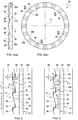
- ⁇ and ⁇ important limit angles in the spatial wedging mechanism, such as intermediate member 90 shown in Figures 1 , 4 , and 9 (the round depicted by the dash and double dots line represents replaceable round table/sectional conic intermediate member ), or an assembled intermediate member 90 including a cup shape housing force limiting member 180 as shown in Figure 2 , 5 .
- the planar wedging mechanism in the prior art corresponds to the present situation, wherein ⁇ 0 (the static friction coefficients of the two friction pairs are close to 0.1), ⁇ 11 °, ⁇ 6° ⁇ 8°, ⁇ ⁇ ⁇ ⁇ . It is obvious that, the physical essence of the working theory/torque transferring is the friction itself but not the friction self-locking of two sets of friction pairs as understood by the preconception of the prior art. Therefore, it is normal for the friction pairs to slid while be overloaded, and the assumption that the self-locking of the traction friction pair will fail when non-structure distortion/damage happens considered by the technical preconception does not exist.
- the structure characteristic that the friction coefficient of the traction friction pair (equivalent weight) is difficult to be increased in the prior art determines that it is impossible to have the movement as indicated in "3" below. 3. when 0 ⁇ ⁇ ⁇ (corresponding to the condition that ⁇ > 0), the traction friction pair is at constantly self-locking state, the guide friction pair is at normal static friction state. Contrary to condition "2", while the guide member 50 is overloaded or over-driven relative to friction 70, the intermediate member 90 has a tendency of slidingly climbing relative to the guide member by overcoming the maximum static friction state/resistance of the guide friction pair.
- the traction friction pair is forced to be maintained at a normal static friction state which equals to self-locking state. That is, the intermediate member 90, the guide member 50 and the friction member 70 are enforcedly integrated into a rotatable integrity, such that there is no relative slidingly climbing even if it is overloaded until being damaged.
- the spatial wedging mechanism is at an absolutely self-locking/wedging state as a diagonal bracing overrunning clutch.
- the limit angle ⁇ is not recognized by the technical theory of the prior art, and is not inspired, conceived, or revealed from the movement relationship of a planar wedging mechanism, and further it cannot be derived from its structure.
- said lead angle ⁇ which is also called wedging angle/jamming angle, is wedging angle of the spatial wedging mechanism of the present invention. Only when 0 ⁇ ⁇ ⁇ , the spatial wedging mechanism wedges, and the overrunning clutch engages.
- Overrunning rotation and counter-overrunning rotation are rotation of rotation mechanism at downstream of the torque transferring passage relative to rotation mechanism at upstream of the torque transferring passage, wherein relative rotation direction of the former one is consistent with the direction of the circumferential force to be transferred by the overrunning clutch, and the direction of the latter one is opposite to the direction of the circumferential force to be transferred by the overrunning clutch.
- the circumferential angle rotated by counter-overrunning movement is called slippage angle, idle rotation angle or engaging angle.
- the overrunning clutch according to the present invention has advantages of reliable wedging, great bearing capacity, high rotation speed, long work life, good overrunning characteristic, light releasing and engaging, high sensitivity of releasing and engaging, easy to adjust and maintain, high efficiency, stable performance while releasing and engaging in high frequency, simple structure, easy manufacturing and assembly, low cost, and convenient control, conveniently obtaining working state of coupler and sliding device, and wide application field and so on.
- the purpose and advantages of the present invention are more clear and obvious with the aid of the following specification and figures.
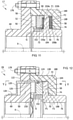
- Embodiment one a wheel-shaft transmission one-way overrunning clutch C1 having axially engaged enclosing casing
- the one-way overrunning clutch C1 includes a friction member 70, which is rigidly integrated with a tubular body 76 and rotates about an axis line X.
- the friction member 70 is preferably provided with a dish-like circle annular having a rotating traction friction surface 72 and a force transfer friction surface 74.
- the inner circumferential surface of the tubular body 76 is provided with a member, such as a keyseat 64, for connecting with an unshown drive shaft.
- the tubular body 76 is encircled by an intermediate member 90 which is preferably in an annular shape.
- the outer circumferential surface 108 of the intermediate member 90 is radially positioned on the inner circumference of a force-limiting member 180, and may slidingly rotate relative to the force-limiting member 180.
- the rotating friction surface 104 on the end surface without tooth is frictionally connected with the traction friction surface 72, and further contacts the friction member 70 at a plane to form a guiding friction mechanism F1.
- a set of helical guiding teeth 92 preferably circumferentially arranged on the other end surface with even spacing are constantly engaged with a preferably annular shaped guide member 50 with helical guiding teeth 52 having a complementary structure on the inner end surface, and therefore, a plane contacting one-way rotation guide mechanism G is formed.
- the rotation guide mechanism G and the traction friction mechanism F1 together form a spatial wedging mechanism of the one-way overrunning clutch C1.
- the cup-shape housing type force-limiting member 180 with a central aperture is secured with the guide member 50 by screws 176 and washers 186 to form an axial force-closed assembled component.
- the assembled component is radially positioned at the outer circumferential surface of both ends of the tubular body 76.
- the intermediate member 90 and the friction member 70 are axially enclosed in the plate shape circular recess formed by said assembled component to form an axial force-closed system.
- a force transfer friction surface 58 of the inner end surface of the annular radial flange force-limiting end portion 188 at the bottom of said cup-shape member is frictionally contacted with the force transfer friction surface 74, and thus form into a rotation surface contacting force transfer friction mechanism F2 which transfer friction torque directly with the friction member 70.
- the outer surface of the assembled component may be provided with curved surfaces (unshown), such as a keyseat, a circumferential belt recess, an annular radial flange friction piece mounting hub, gear teeth, or end surface screw holes etc.
- the connect and fasten means may be selected from the group consist of any of the rivet joint, welding, interference fit, bolt, screw thread pair capable of frictionally self-locking formed between the corresponding inner and outer circumferential surfaces and rotating in the same direction as the rotation guide mechanism G, clip ring, pin, key, telescoping or wedging means.
- the guide member 50 in Figure 10 itself is provided with a special structure such as a force-limiting end 188, and thus, there is no need of any other connection member since the guide member 50 itself serves as a force-limiting member.
- the guide member 50 may be attached to and circumferentially secured to the inner circumferential surface of the force-limiting member 180 by splines, and then, the axial outer screw thread of the guide member 50 is connected to the annular end cap of the force-limiting member 180 to provide an axial supporting and one-way limiting connection. Therefore, the aim of axial force closure of clutch C1 is achieved.
- Figure 3-4 show the detailed relationship and structure of rotation guide mechanism G and intermediate member 90.
- each pair of helical guide teeth 52 and 92 extends radially.
- Their respective guide surfaces 54 and 94 are toward single circumferential direction and both have complementary helical tooth flank and lead angle ⁇ .
- the guide surfaces 54 and 94 are pressed on each other to form a set of helical guide friction pair, wherein, 0 ⁇ ⁇ ⁇ .
- non-guiding surfaces 56 and 96 with clearance therein are parallel with axis X, to ensure that the circumferential encounter of said faces would not result in wedging.
- the guiding teeth 92 further includes teeth top surfaces 98 and teeth bottom surfaces 102.
- a plurality of guiding teeth 52 on the end surface of the guide member 50 are actually the wedging teeth of the spatial wedging mechanism.
- the guiding surfaces 54 of above said guiding teeth 52 approach circumferentially along the axis toward the traction friction surface 72 of the friction member 70, and thus form a plurality of end surface wedging spaces extending along the circumference therein.
- the plurality of guiding teeth 92 provided within said wedging spaces are wedges, which are rigidly integrated into the annular intermediate member 90.
- the elastic keeping mechanism is actually a torsion spring 150 provided in the inner hole of the rotation guide mechanism G, and a radial hole 112 formed in the inner circumferential surface 106 of the intermediate member 90 and a corresponding hole formed in the inner circumferential surface of the guide member 50 to accommodate the both end of said torsion spring 150. Then, the intermediate member 90 is retained at the pre-wedge position located at the minimum end along the circumferential direction of the wedge space, such that the intermediate member 90 is about to be wedged anytime.
- the guide surface 94 and the rotating friction surface 104 are elastically pressed against the guide surface 54 and the traction friction surface 72 as the wedging surface of the spatial wedging mechanism all the time.
- the maximum radial clearance of the rotation guide mechanism G is ⁇
- the maximum circumferential clearance/degree of freedom is ⁇ , furthermore, both of above two values are preferably greater than zero.
- the working process of the one-way overrunning clutch C1 is very simple.
- the friction member 70 may drive the intermediate member 90 of the rotation guide mechanism G to conduct rotation guiding movement relative to the guide member 50 with the help of zero load/traction friction torque of the traction friction mechanism F1.
- the axial movement/expansive force generated by the rotation guiding movement of the mechanism G wedges the guide teeth 92 in the end surface wedging space enclosed by the guide surface 54 and the traction friction surface 72 immediately, that is the intermediate member 90 wedges and combines the guide member 50 and the friction member 70 into a single rotation unit.
- the friction member 70 is expanded to be pressed against the force transfer friction surface 58, which is the inner surface of the force-limiting member 180, to form the axial force closure which lead to the engagement of the force transfer friction mechanism F2.
- the guide member 50 is directly coupled with the friction member 70 to form a single rotation unit.
- the driving torque M 0 input from the characteristic surface of the force-limiting member 180 is divided into wedging friction torque M 1 which is transferred through the rotation guide mechanism G and the traction friction mechanism F1, and force-transferring friction torque M 2 which is transferred directly via the force-transferring friction mechanism F2, and then are delivered to the friction member 70 respectively.
- the torque is transferred to the drive shaft circumferentially secured within the inner hole of the tubular body 76 via said tubular body 76.
- M 0 M 1 + M 2 .
- the torque may be transferred reversely without any substantial difference.
- the clutch C1 would be disengaged and start the overrun rotation, wherein the intermediate member 90 would frictionally slip relative to the friction member 70 following the guide member 50.
- the intermediate member 90 would be retained at the pre-wedging position stably to prepare for the fast wedging next time.
- the torque would be transferred via surface contacting pair within the clutch C1.
- the passage of the torque transfer does not include any discrete or asymmetrical rotation member, as well as any radial force or components therof.
- the one-way overrunning clutch C1 with spatial wedging mechanism according to the present invention not only overcomes the conventional idea and preconception, but also possess substantive advancement and significant advantage in all aspects, and further possess almost all features of an ideal overrunning clutch.
- the wedging state is only related to three rigid members of the assembled guide member 50, the intermediate member 90, the friction member 70, especially to the axial rigidity.
- the assembled guide member 50 with lowest rigidity axially has two annular inner radial flanges.
- the axial span of the guide member 50 is much smaller than the radial span of the member in the prior art, and the guide member 50 has the direct connection with fasteners.
- the axial force is act on surfaces other than the discrete spots or lines. Therefore, the rigidity of the member 50 are much higher than the radial rigidity of the completely hollow inner and outer ring in the prior art.
- the wedging/lead angle ⁇ would be maintained. Even though the value of ⁇ may vary due to the change of relevant friction coefficient, the variation may be estimated in advance and thus a safe allowance could be given. Therefore, within the entire life circle of the clutch C1, the wedging/lead angle ⁇ would always be less than the limit angle ⁇ . Furthermore, the quantity of members of the clutch C1 is reduced by times, and there is no small discrete member and kinematic pair. Thus, the clutch C1 according to the present invention may possess very reliable wedging capability and working reliability, so it has advantage over the structure of annular hollow ring, which suffers from mechanical wear, discrete radial force, and tendency of radial elastic distortion, in the prior art.
- the clutch C1 would still slip.
- said skid is not because of the failure or destruction of the friction self-locking according to the conventional understanding of the prior art. Said skid is normal sliding and rotation status when the value of the lead angle is within above range, and the clutch C1 would return to non-sliding status when the overload factor is eliminated. Therefore, the clutch C1 with the aforsaid lead angle may be used as a self-adapting overloading-prevention friction type one-way safe clutch, or as a one-way clutch in a starter. The clutch C1 works in one direction, so reverse transmission would not result in above consequence.
- the driving torque introduced from the friction member 70 is not possible to exceed the total static friction torque of the friction mechanisms F1 and F2, wherein the total static friction torque is equal to the loading torque when the clutch is overload, thus, the clutch would not slid even it is overload.
- the traction friction mechanism F1 would never skid during the process of frictionally self-locking, even if it is overload.
- this range of lead angle would not be selected.
- said range of lead angle may be preferably adopted.
- the present invention includes the technical advantage of increasing the value of the limit angles ⁇ and ⁇ , to acquire improved loading capacity, wedging/releasing capacity, reliability, slippage angle, axial force, and surface contact strength of clutch C1. with greater design freedom.
- the guiding surfaces 54 and 94 of the rotation guiding mechanism G are configured into inclined helical surfaces, and at least the traction friction surface 72 of the traction friction mechanism F1 is arranged into a conical surface, such that the angle between the guide surfaces 54 and 94 in the axial sectional surface, as well as the angle between the traction friction surface 72 and the axis X are not 90 degree, but are 0 - 180 degree as illustrated in Figures 8-10 , 15-19 .
- the traction friction mechanism F1 is configured into the structure containing a plurality of friction pieces shown in Figure 11 ; the guide surfaces 54 and 94 are spaced apart by cone roller/ball bearing/drum roller bearing; and material/element with greater coefficient of friction are attached to at least one of the friction surfaces 72 and 104.
- the statistic friction coefficient is 0.1, and the elastic pre-fasten force is ignored, the values of ⁇ and ⁇ of the clutch C1 are equal to 0 and 11.4 degree respectively (identical with the planar wedging mechanism of the prior art).
- the above limit angles may be increased to 11.0 degree and 22.4 degree respectively, as long as the traction friction mechanism F1 is configured to be a two-piece type friction mechanism. It should be understand that, the limit angles ⁇ and ⁇ are defined and explained clearly in the present specification, such that those skilled in the art may conclude the function relationship/equation without any inventive work.
- the friction mechanism F1 and F2 may have a structure of a plurality of friction pieces as shown in Figures 10-11 , or is attached with mechanism containing material/element with greater friction coefficient, or is a frusto-conic surface pairs with the semiconical vertex angle between 0 ⁇ 180 degree as shown in Figure 15 . Therefore, given the same external diameter of the clutch or the same rotation friction external diameter, the torque transferring capability of the clutch C1 could be at least duplicate or ten times larger than that of the prior art. In other way, given the same bearing capability, the external dimension is much smaller, such that the clutch of present invention possesses greater design freedom and capability to fulfill the practical requirements.
- the quantity of the dry and wet friction pieces could be 10 and 30 respectively at most.
- the potential of the bearing capacity of the clutch is huge, and the clutch may acquire bearing capacity not less than the limit bearing capacity of corresponding drive shaft or driving wheel comparing with relatively small external diameter. Said bearing capacity of the clutch may exceed the bearing limit of one million Newton meter in the prior art.
- the clutch C1 may distribute the torque flow into wedging friction torque M 1 and force transfer friction torque M 2 in any proportion, such as M 1 is 20% of M 2 . Accordingly, said technical method could resolve the confliction between increasing the bearing capacity and reducing the contacting strength of the guiding surface on the basis of the low pair.
- the two torque flow transmission of the clutch C1 has the feature of a "power amplifier".
- the structural advantage of the present invention are as follows: the main members do not have non-zero centrifugal force; the friction torque or the resistance torque of the traction friction mechanism F1 and the force transferring friction mechanism F2 are not related to the rotation rate; and in addition, the friction resistance torque when the clutch is overrunning could be reduced by controlling the strength of the spring 150.
- the clutch C1 could transfer torque much greater than that of the prior art at the rotation rate much higher than that of the prior art.
- the high rotation rate almost depends only on the strength of related material. That is very good for extra high rotation rate power transferring in such as twin engine helicopter.
- the clutch C3 only balance weight is needed.
- a steel ball inclined surface centrifugal mechanism may be arranged between the intermediate member 90 and the inner circumference of the force limiting member 180, to realize non-contacting overrunning rotation of the clutch C1.
- a steel ball received in corresponding radial aperture of the external circumferential surface 108 of the intermediate member 90 may use the centrifugal force thereof, and press the corresponding inclined surface on the inner circumferential surface of the force limiting member 180 when the overrunning rotation rate is greater than a setting rotation rate, such that the axial force of the spring 150 may be overcome with the help of the axial component force of the counterforce of the inclined surface, and the intermediate member 90 is pressed to disengage from the friction member 90, or at least the contacting pressure between above two members are zero.
- an actuate mechanism including such as the directional ring 120 in Figure 12 may be attached to the guide member 50 or the force limiting member 180 to directly pull or push the intermediate member 90 away from the traction friction surface 72 along the axial direction.
- the intermediate member 90 could be retained at the position to be wedged.
- the wedging or releasing of the spatial wedging mechanism do not need any perceivable geometric movement of the intermediate member 90, that is, there isn't any inertial mass within the clutch C1. Therefore, said mechanism has a high responsivity of releasing or wedging at the very first timing in response to overrunning or counter overrunning rotation.
- the clutch C1 has high sensitivity of disengaging/releasing and engaging, and is fast when disengage and engage.
- the axial and circumferential rigidity is high, or the axial and circumferential elastic deformation is much smaller than the radial elastic deformation, therefore, the difference between the wedging position of the intermediate member 90 and the pre-wedging position of the intermediate member 90 before wedging is much smaller than that of the prior art.
- the clutch C1 has a smaller slippage angle or higher engage sensitivity. Said slippage angle is close to zero theoretically and practically. Further, the high precision transmission would be realized and maintained with ultra low wearing intensity. Said high precision transmission includes the overrunning in response of very small circumferential swing (such as the condition of approximately zero rotation rate output in a pulsation continuously variable transmission).
- the present embodiment could also rigidly define the theoretic maximum slippage angle by controlling the circumferential clearance ⁇ between the guide teeth 52 and 92 in addition to the spring 150. Even though the rotation radius is very small, the slippage angle could be efficiently defined as controlling the precision of the geometry dimension. In the current design, manufacturing and assembly techniques, it is easy to realize the circumferential clearance ⁇ based on entirely rigid geometry dimension. For example, the value of the circumferential clearance s could reach the level of 0.001 ⁇ 0.01 ⁇ 0.1 millimeter easily. Said level corresponds to circumferential angle 10.3 second ⁇ 1.7 minute ⁇ 17.2 minute of a 40 millimeter external diameter.
- the slippage angle corresponding to a 65 millimeter external diameter has reached 2 degree, and the slippage angle corresponding to a 200 millimeter external diameter is as much as 30 minute.
- the circumferential elastic restrain mode depending on the pre-fasten of a spring cost too much to reduce the slippage angle for realizing high precision transmission, wherein greater wear and tear and short life circle would occur due to the increased elastic pre-fasten force. Said conditions would not exist in the present invention. Accordingly, the clutch C1 is more suitable to complete the high precision transmission such as in color printing. Said transmission capability could be retained for longer time because of the ultra low wearing intensity.
- a set of end face helical guide teeth 52, 92 is preferably arranged with zero clearance therebetween, and circumferentially extending along corresponding inner and outer circumferential surface as show in Figure 10 in the form of single or a plurality of thread, and a torsion spring 150 is preferably mounted, the transmission ability with high precision within the full life circle would be maintained constantly without any adjustment or special maintenance.
- radial, circumferential and axial passage may be formed on both friction surfaces of the rotation friction pairs of said friction mechanism F1 and F2 or inside relevant elements, such as the friction member 70 and the intermediate member 92 at the same time or respectively, such that the gas or liquid passing through could take way heat generated from friction, and could quickly enter and leave respective friction surface to ensure the release and engage sensitivity of the clutch C1.
- the affect of the wear could be counteract, the high precision transmission could be maintained, and the life circle of each component could be prolonged.
- the present invention does not set specific limit to the rotation guide mechanism G and its end surface guiding teeth 52, 92 specifically.
- the mechanism G and its guide teeth could be any form or shape capable of rotation guiding.
- the guiding teeth could either be arranged on the end surface/circumferential surface discretely, or be arranged on the inner/outer circumferential surface continuously along the circumference. In the latter arrangement, it could be helical teeth with sectional shape of rectangle, trapezoid, serration, or triangular.
- the rotation friction surfaces of the friction mechanism F1 and F2 may rotate about any curve/generatrix, only if said surfaces axially engage with each other complementarily.
- the present invention is preferably provided with elastic pre-fasten element/spring 150.
- the purpose of above arrangement is to ensure the intermediate member 90 being kept at the pre-wedging position all the time. Therefore, the intermediate member 90 could respond to the change of relative rotation direction of the clutch while having a constant traction friction torque. Consequentially, the intermediate member 90 may simultaneously wedge at the very initial time of the counter overrunning rotating, thus the counter overrunning rotation may be stopped initially and the slippage angle is approximate to zero.
- the spring 150 used in the present invention is not limited to the form of torsion spring, and is not limited to the installation position of an inner hole. There is no limit to the particular shape, quantity, and installation position only if said purpose is ensured.
- said pre-fasten element could be elastic member of a torsion spring, a compressed spring, a tension spring, a plate spring, a diaphragm spring, a wave shape spring, a straight steel wire/leaf spring made from any material; said pre-fasten element could also be mounted at one side of the inner and outer circumferential surfaces, either side of the two end surfaces, or inside of the rotation guide mechanism G.
- the method of having a set of compressed spring or straight steel wire/plate received partially inside a group of axial counter bores in the top surfaces of the guide teeth 52 or 92 respectively would use least space.
- a torsion spring or a torsion spring that could be compressed axially is suitable to be used in high precision transmission.
- the idle/traction friction torque acted on the intermediate member 90 is preferably not great enough to balance the circumferential counterforce of the spring 150 and lead to the disengagement of the guide surfaces 94, 54. Additionally, the axial force provided by the spring 150 and corresponding idle/traction friction torque may be small enough, and is almost unrelated to the rotation rate and bearing capacity of the clutch. There isn't obvious variation as to the working condition of the spring 150 during use. Therefore, ordinary low cost spring could be used as there isn't any other additional requirement.
- the friction member 70 and the tubular body 76 in the clutch C1 could be rigidly formed as an integral member or circumferentially joint with spline (equal to an overrunning clutch without inner ring) to self-adjust its axial location, and ensure all the axial forces are absolutely enclosed within the assembled guide member 50, such that the bearing 158 would not endure any axial force.
- the mechanism G and mechanism F1 in clutch C1 could turnover about the axis. That is, in the transformed clutch after the position exchanged, the friction member is a force-closed assembled component including a cup shape force-limiting member 180, and the guide member rigidly integrated with the tubular body 76 forms a force transfer friction mechanism F2 together with the force-limiting member 180.
- the structure of the above member is as shown in Figure 14 .
- the two intermediate members being symmetric with each other about the axis could share the same guide member having double end surfaces guide teeth, thus said clutch is changed into an axial duplex one-way overrunning clutch. Accordingly, the spatial wedging mechanism is much easier to de-wedge/release.
- an axial abutment enclosing case is adopted in the clutch.
- the best choice is to use rigidly integrated bag shape enclosing case or radial abutment enclosing case.
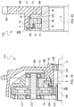
- the one-way overrunning clutch C2 as shown in Figure 2 could be formed by removing the spring 150, and rigidly integrating the tubular body 76 extending above the traction friction surface 72 in the axial direction with the intermediate member 90.
- the guide member 50 is equipped with tubular body 60;
- the intermediate member 90 is a force-closed assembled member including a cup shape force limiting member 180;
- the rotation friction surface 104 is arranged on the inner surface of the force-limiting end 188 and the force transferring friction surface 58 is provided on the end surface without tooth of the guide member 50.
- the most prominent feature of the clutch C2 is the wedging mode and corresponding force bearing condition, which has changed from the conventional interior wedging mode of the wedging mechanism located within the wedging space and pressed by the force from outside toward inside into an exterior wedging mode of the wedging mechanism having wedging space itself and expanded from inside toward outside by pressing force. Except from the force bearing condition and corresponding change of the position of the mechanism, for example, the guide member 50 is frictionally connected with the friction member 70 directly, there isn't any substantial difference.
- the intermediate member 90 no longer directly or indirectly contacts the friction member 70 constantly to perceive the rotation of the friction member 70 and the guide member 50 relative to each other, and the traction friction torque for wedging cannot be obtained; only the slippage angle is affected.
- the guide member 50 could still quickly change relative to the rotate direction of the intermediate member 90, such that the intermediate member 90 may wedge by inertial force to transfer torque.
- the overrunning transmission of high frequency direction alternation in impulsion stepless transmission is a good example.
- the mechanisms G and F2 in clutch C2 may swop positions axially with each other, that is, the guide teeth 52, 92 are provided between the guide member 50 and the friction member 70. Therefore, the clutch C2 turns into a dual-circumferential or single-circumferential clutch based on working condition of the force-closed assemble mechanism including the force-limiting member 180. Additionally, the intermediate member 90 of the clutch C2 may be divided into two independent members of an intermediate member and a plane ring. The plane ring is connected with the force-limiting member 180 to form a force-closed assemble mechanism. The friction member 70 still transfers torque toward outside. Certainly, the structure of the clutch is equal to that shown in Figure 14 if the friction member 70 is removed.
- the elements of the clutch C1-C2 are not all essential to the application of the present invention.
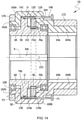
- the non-full circle wedging force-transfer wheel-shaft transmission type one-way overrunning clutch C3 only includes three essential components.
- the exterior surface of the bag shape annular friction member 70 for axial force-closing is provided with force transferring features such as key slot 64, gear teeth, screw hole/pin hole or belt groove.
- the inner circumferential surface 84 of the friction member 70 is provided with a plate shape annular groove 78 in the middle along the axial direction.
- the inner surface of an exact half circle of the annular groove 78 preferably extends radially in parallel to the outer surface of the friction member 70 along the tangent line H and forms a quadrangle through hole 82. Therefore, the inner circumferential surface 80 of the annular groove 78 is extended to have an inner radial surface with U-shape cross section.
- the guide member 50 and the intermediate member 90 engaged with each other may be received in the annular groove 78 along the direction directed by the hollow arrow via the through hole 82.
- the outer radius of the intermediate member 90 is slightly larger than that of the guide member 50, such that it could frictionally contact the inner circumferential surface 80 during the radially movement to acquire the friction force needed for wedging.
- the inner circumferential surface 84 of the friction member 70 and the splined shaft circumferentially attached in the inner hole of the guide member 50 are provided with corresponding radial clearance therebetween.
- the above arrangement is especially suitable for using in hinge mechanism or one-way/two-way spanner/screwdriver which may work continuously.
- the guide member 50 or the intermediate member 90 are directly disposed on an inner end surface of the friction member 70 in Figure 6 , or the direct or indirect circumferential attachment is realized with the help of U shape outer circumferential surface, splined hub inside the hole, axial/radial pin in the inner surface having complementary configuration and so on, then a bag shape guide member or intermediate member with axial force-closed function can be obtained. While assembling, an intermediate member or guide member may be installed in advance along the radial direction, and then a friction member may be installed after the engagement along the axial direction.
- the bag shape mechanism may be a single force-limiting member, and may be sealed by the ring firmly attached on the outer circumferential surface.
- the clutch C3 may achieve the positioning of elements thereof via members such as splined shaft through the clutch C3 axially.
- the clutch C3 can be enclosed and assembled by the following method during assembly.
- a circumferential tongue capable to radially bend inward may be cut out in advance at a position, which corresponds to the circumferential end 88 and corresponding only to the guide member 50 axially, at both radial side surfaces of the through hole 82.
- a radial tongue capable to axially bend inward may be cut out in advance at the radial outer ring side 86 in the center of the inner end surface of the through hole 82 that is coplanar with the force-transfer friction surface 74.
- said circumferential tongue or radial tongue may be plastically bend after the guide member 50 and the intermediate member 90 are assembled in position, to realize the assembly and positioning of said two members.
- the force-transfer friction mechanism F2 is not essential either.
- the three-component overrunning clutch C4 in ⁇ shaft-shaft transmission form of inner wedging mode may be supported by two transmission shaft coaxially fastened with the guide member 50 and the friction member 70 respectively, and then an axial force-closed system is formed not by the clutch itself but by the frame.
- the intermediate member 90 may preferably be an expand type or contract type elastic open ring.
- the intermediate member 90 is not necessary to have a full circular shape, and it could be the form of a plurality of discrete elements as shown in Figure 9 . Therefore, the intermediate member 90 may move axially and radially at the same time and transfer corresponding action force.
- the friction member 70 is a force-enclosed assembly member containing a cup-shape casing force-limiting member 180.
- a plurality of intermediate member 90 such as steel ball or a circular platform/ conical rollers located on a cone rotate surface Z having a semi-conic top angle of ⁇ , are correspondingly received in a set of circumferential tooth recesses of cone shape/tapered helical teeth type guide teeth 52 on the end surface of the cone,
- the rotation side surface is not only a guide surface but also a friction surface.
- the intermediate member 90 is pressed against the traction friction surface 72 of inner conical surface type constantly.
- the rotation guiding mechanism G and traction friction mechanism F1 of the overrunning clutch C5 are both higher pairs in point/line contact, as referring to the round depicted by the dash and double dots line in F1.
- the clutch C5 is not as good as the clutch C1 in the capability, it is still superior to that in the prior art because of the high axial rigidity and above described advantages of the force transfer friction mechanism F2.
- the roller type overrunning clutch of the prior art is just a special example when the angle ⁇ of the clutch C5 equals to 0 or 180 degree, that is a special example providing the traction friction mechanism F1 with radial, not axial, engaging force. Because of lack of axial movement, the spatial wedging mechanism is simplified into a plane wedging mechanism with only radial movement.
- the clutches C1-C4, C7-C9 correspond to the condition that their angle ⁇ , specifically the semi-conic top angle of the cone rotation surface on which the contacting point/line of the traction friction pair of the mechanism G, is equal to 90 degree.
- the clutches C6, C10-C15 are corresponding to the condition that 0 degree ⁇ ⁇ ⁇ 180 degree and ⁇ # 90 degree.
- the intermediate members 90 are preferably united with each other to form a single rigid body/integrity body, because they are not need to move radially or rotate.
- the overrunning clutch C6 is actually a modification of the clutch C1.
- a set of end surface helical guide teeth 52, 92 of the rotation guide mechanism G are in the form of single thread or multiple threads, and circumferentially continuously formed on the inner circumferential surface of the guide member 50 and the outer circumferential surface of the intermediate member 90.
- An annular end cap 174 is fastened on the open end surface of the guide member 50 rigidly integrated with the force-limiting member 180 by bolts 176.
- the wave shape spring 150 is arranged between the annular end cap 174 and the intermediate member 90, and only the intermediate member 90 is pressed against the friction member 70.
- the force transfer friction mechanism F2 is configured as a clutch mechanism with multiple friction pieces, such that the torque transferred directly by the force transfer friction mechanism F2 is multiple times of the traction friction mechanism F1. Therefore, a set of relatively small friction pieces 156 including at least one friction piece are circumferentially fastened on the corresponding stepped outer circumferential surface of the tubular body 76 by a splined connection. Another set of larger friction pieces 154 staggered axially with said friction pieces 156 are fastened on the corresponding stepped outer circumferential surface of the guide member 50 by splined connection.
- the shaft-shaft transmission overrunning clutch C7 in Figure 11 contains force transfer friction mechanism F2 with multiple friction pieces.
- the traction friction mechanism F1 also adopts multiple friction-piece structure, and thus containing a set of traction friction pairs with more than one traction friction pair.
- the elastic keeping mechanism includes a contract type elastic open ring sensing member 152, which is circumferentially fastened on the inner circumferential surface of the intermediate member 90 by a spline and elastically compressed on corresponding outer circumferential surface of the tubular body 76 to form a sense type rotation friction pair.
- the intermediate member 90 may still be immediately wedged by traction friction torque, such that the clutch C7 engages immediately to transfer torque.
- the above design reduces the wear and tear of the traction friction mechanism F1 and the force transfer friction mechanism F2 as well as the overall idle resistance torque.
- the fastener used in the assemble guide member 50 are replaced with screw 178.
- the clutches C6, C7 are preferably used in transferring large torque, and transmission section with low requirement in the precision of transmission, engaging frequency or slippage angle.
- the purpose of restricting the maximum circumferential clearance ⁇ of the transmission guide mechanism G for realizing high engagement sensitivity and small slippage angle can be achieved only if at least a circumferential position restricting mechanism, such as a radial or axial pin slot engage mechanism, is installed between the intermediate member 90 and the guide member 50 or the annular end cap 174.
- the position restricting mechanism may be partially formed with elastic material or circumferentially arranged with spring 150, thus. above described elastic keeping mechanism is formed actually.
- the two-way overrunning clutch C8 comprises the main structure of the clutch C7.
- the elastic keeping mechanism includes two components, which are wave shape spring 150 and a full ring sensing member 152, which is pressed against the traction friction surface 72 by the spring 150 to form a sensing type rotation friction pair together with the traction friction surface 72.
- each pair of helical guide teeth 52, 92 are circumferentially symmetrically equipped with two helical guide surfaces 54, 94, which have an lead angle of ⁇ and complement with each other.
- An orientation mechanism D is equipped for guiding the working direction of the clutch C8.
- the main body of the mechanism D is an orientation ring 120, which includes a set of axial orientation pins 122 and tubular section 128 capable to rotationally and slidably cover the tubular body 60.
- a radially inward cylindrical protrusion 124 provided at the head of the orientation pin 122 and extending through an axial reference hole/slot 126 of the guide member 50, may be slidably received in the corresponding guide groove 130 on the outer circumferential surface of the intermediate member 90 from one open end, to form a cylindrical cam type pin-slot engage mechanism with circumferential clearance near zero.
- the circumferential degrees of freedom of the orientation ring 120 in both circumferential direction with respect to the guide member 50 are all above zero and not larger than the circumferential degree of freedom ⁇ of the rotation guide mechanism G at that time. That is to say, 0 ⁇ ⁇ 1 ⁇ ⁇ and 0 ⁇ ⁇ 2 ⁇ ⁇ , wherein ⁇ 1 is preferably equal to ⁇ 2, referring to Figure 13(a) .
- the guide groove 130 as a multiple section of groove assembly, includes axially a forward section 132 receiving a protrusion 124, a backward section 134 circumferentially separated from said forward section 132 with a circumferential angle ⁇ , and a transition section connecting the above two sections. While the working direction of the clutch C8 is forward, that is the torque and overrunning movement are transferred only forwardly, the clutch C8 is equal to the one-way overrunning clutch C1 working in counter clockwise direction.
- orientation mechanism D may be used in stepless control of the circumferential clearance ⁇ of the one-way overrunning clutch, for constantly maintain the transmission precision.
- the one-way overrunning clutch working in opposite direction or the one-way overrunning clutch with radial abutment assemble housing as shown in Figure 14 may be dually connected correspondingly in the way of rigidly integrating or sharing a common orientation mechanism D by a force limiting member, then a two-way overrunning clutch having the same torque capacity as a one-way overrunning clutch may be obtained.
- the effect of the orientation mechanism D is to selectively define the circumferential rotation range of the intermediate member 90 with respect to the orientation member 50, and then the abutment of the guide surfaces 54 and 94 about the circumferential direction set in advance may be permitted or prevented, such that the rotation guide mechanism G may or may not guide the rotation in said circumferential direction.
- the clutch C8 is defined as a one-way overrunning clutch in the circumferential direction, to achieve the purpose of restricting and controlling the working direction. Consequentially, there is no need to repeat the working process of transferring torque and overrunning of the one-way clutch C8.
- the orientation mechanism D may be provided with different definition or combination of different definition, to allow or prevent the guide surfaces 54 and 94 pressing against each other corresponding to 0-2 circumferential direction.
- the overrunning clutch which is controllable in its direction comprises all possible orientation status and corresponding working condition.
- the guide groove 130 in Figure 13(a) may be replaced by the guide groove 130 in Figure 13(b)-(f).
- Figure 13(b) is an orientation solution suitable to be used in one-way slider of a motor vehicle or fishing reel of a fishing pole.
- the guide surfaces 54 and 94 corresponding to two circumferential direction may be pressed against each other without being restricted.
- the clutch would be a friction coupler overrunning in zero direction and transferring torque in two directions. Therefore, above orientation solution used in power transmission of ship may efficiently prevent the harmful collision to the clutch by the transient separation brought by storm.
- the clutch C8 can have the function of a safe clutch when it is in a coupler working condition. Further, if the orientation mechanism D, the sensing member 152, and the spring 150 in the clutch C8 are removed, the circumferential angle ⁇ is preferably set at zero, and the guide member 50 is coupled with the prime actuator, then the clutch C8 would turns into a two-way friction safety clutch/coupler without idle travel, wherein the overload torque is unrelated with the friction coefficient and the clutch is precisely self-adapted to the driving torque. Then, the problem of precisely setting and constantly maintaining the overload torque would not exist any more. Furthermore, while the clutch of the present invention is used as a coupler, it may have the ability of self-adapting to any eccentric degree to certain extent.
- the guide groove 130 in Figure 13(d) is provided with a neutral section 138 for replacing the free section 136.
- the neutral section 138 is located circumferentially the middle position between the forward section 132 and the backward section 134.
- the upper limit of ⁇ 1 and ⁇ 2 are needed to be less and ⁇ /2. Therefore, when the protrusion 124 is located axially within the neutral section, the orientation mechanism D would cause the guide surfaces 54 and 94 to be unable to be pressed against each other in two circumferential directions. That is to say, the guide surfaces 54 and 94 are pressed against each other in zero direction. The rotation guide mechanism G will then be at an invalidation condition.
- the clutch would absolutely overrun in two directions and transfer torque in zero direction.
- the overrunning clutch with the orientation scheme shown in Figure 13 (d) would be especially suitable in dual power driving system needing power switching and online maintenance any time and may be used to replace the SSS synchronous clutch used in large-scale ship as well as power unit.
- the orientation scheme shown in Figure 13(e) would better suitable to be used in ships because the reverse transmission is rarely employed.
- the clutch could be used as a stepless orientation hinge.
- the overrunning clutch with controllable direction would comprises absolute separating idle condition, forward condition, coupler condition and backward condition in the simplest manner.
- the clutch would fulfill the most complex practical requirements.
- the purpose of providing the orientation mechanism D is to selectively cancel the rotation guide function of the rotation guide mechanism G in zero, one or two circumferential directions, and then define the working direction of the two-way overrunning clutch. Therefore, any rigid/flexible mechanism or device capable to realize above function may be used as an orientation mechanism without any other limitation.
- the orientation mechanism may be mounted radially outside, inside the rotation guide mechanism G, radially in the same position with the rotation guide mechanism G, or at one side of the end surface of the rotation guide mechanism G
- the orientation mechanism may also including an elastic keeping mechanism, for example, an axial or radial pin-slot engaging mechanism with at least one protrusion and at least one slot.
- Said axial or radial pin-slot engaging mechanism is provided between the intermediate member 90 and the guide member 50, or the force-limiting member 180 circumferentially integrally rotating with above two members, or the rotating shaft. It is a good choice to adopt the engaging method using eccentric pin and eccentric slot capable of rotating, and furthermore, it is convenient to install any kinds of spring to elastically define the circumferential clearance. With regard to this aspect, it has been disclosed in prior art. For example, many embodiments have been disclosed in the patent applications of CN101117987A and CN101672335A by the present applicant.
- the cylindrical cam type pin-slot engaging mechanism in Figure 12 may be repetitively arranged between the tubular section 128 and the tubular body 60, only if the circumferential freedom degree between the orientation pin 122 and the reference hole 126/slot is adapted to not obstruct the rotation of the orientation ring 120 relating to the guide member 50.
- the guide groove 130 in Figure 13(a) is changed to a purely axial reference guide groove to make the orientation ring 120 circumferentially secured relating to the intermediate member 90.
- the relevant embodiments may be referred to in the description regarding Figure 47 and Figure 48 in the patent application CN1011 17987A .
- a recess elastic positioning mechanism may be provided between the tubular section 128 and the tubular body 60, to ensure the working position of the orientation mechanism D is steady and the working direction is stable.
- the orientation ring 120 should be actuated preferably by elastic member such as spring,
- the position of the orientation mechanism D may be moved to the position pointed by K in Figure 13(a) , the circumferential width of the guide groove 130 may be widened properly, and the circumferential clearance placement effect is ensured. That is, comparing with the driving rotation of the orientation ring 1 20 in the two circumferential directions, the intermediate member 90 rotating reversely cannot wedge because of circumferentially abutting with the orientation pin. Then the clutch C8 turns into a two-way overrunning clutch with a pusher dog, in which the orientation ring 120 used as the pusher dog transfers torque to the guide member 50.
- an end surface force transfer engagement mechanism may be positioned between the pusher dog/orientation ring 120 and the guide member 50.
- the pusher dog/orientation ring 120 is preferably connected to the inner circumferential surfaces of both the guide member 50 and the intermediate member 90 with a spline, and the overall structure in Figure 14 may be used.
- the friction member 70 of the clutch C9 is a force-closed assembly mechanism rigidly integrated with two semicircle cover type force-limiting member 160.
- the major difference between embodiment four and the embodiments described before is that the force-closed assembly mechanism is formed by radial abutment of two symmetrical semicircle covers, which are rigidly integrated in the axial direction and have coplanar inner end surfaces so that to provide the highest axial rigidness and strength to transfer large torque.
- the force-limiting members 160a and 160b is a revolution body formed by revolution of an entitative generatrix generally in a "U" shape for half circle about axis X, to form a circumferentially intact enclosed housing by radially clamping two bearings 158 covering each end of the tubular body 60. Therefore, the guide member 50 and the intermediate member 90 may be rotatablely enclosed in the plate shape annular groove formed by above enclosed housing.
- Two pairs of semicircle end surface flanges 162a and 162b as well as 164a and 164b at both outer ends of two force-limiting members are radially joint and then forms two full circular end surface flanges.
- Annular collars 170 and 172 are attached on the outer circumferential surfaces of the flanges at the same diameter with an interference fit. Therefore, two force-limiting members 160a and 160b are fastened into a fixed integrity/assembled component.
- the clutch C9 may be wheel-shaft transmission form, or further, become a one-way overrunning clutch transferring large torque by removing the orientation mechanism D.
- This can be achieved by the arrangement that the shape and installation position of the end surface flange 164 and the annular collar 172 are adapted to be axially symmetric with the end surface flange 162 and the annular collar 170 at left side.
- the annular collar 170 may be disposed on the outer circumferential surface of axially middle portion of two force-limiting members 160 by way of interference fit, rectangular hole, key connecting, or by one of the annular collars 170 being replaced by a toothed ring.
- two force-limiting members 160 may be fastened into a fixed integrity by welding, rivet joint, or screw.
- the tubular body 60 extending toward right direction on the guide member 50 may be removed, and the friction member 70 is independent to the force-limiting member 160, to obtain a shaft-shaft transmission overrunning clutch.
- the force-enclosed assembly housing/component is formed solely by force-limiting member, and the assembly housing/component is equal to a friction piece for transferring torque in the force transfer friction mechanism F2,
- the elastic expanding open ring sensing member 152 for reducing the wear is elastically stretched on the inner circumferential surface of the intermediate member 90, to form a sensing rotate friction pair.
- the protrusion 153 located at an end surface of the sensing member 152 is movably inserted in a recess (not shown) between the opposite surfaces of the friction members 70a and 70b, to enable the sensing member 152 to rotate with the friction member 70.
- the orientation ring 120 of the orientation mechanism is axially located between the inner circumferential surface of two force-limiting members 160 and the outer circumferential surfaces of the guide member 50 and the intermediate member 90.
- Each end of the inner circumferential surfaces of the orientation ring 120 is provided with protrusion 124a and 124b.
- the protrusion 124a is axially received in the guide groove 130 on the outer circumferential surface of the guide member 50
- the protrusion 124b is axially received in the reference hole/slot 126 on the outer circumferential surface of the intermediate member 90.
- an actuator including an actuating ring 140 and a wave shape spring 142 is provided as an actuating orientation mechanism D.
- the actuating ring provided with a group of axial actuating pins on its end surface may be slideably attached at the corresponding outer circumferential surfaces of two force-limiting members 160.
- the actuating ring 140 may move the orientation ring 120 to the left with the actuating pins and axial holes on the force-limiting members 160, to change and fix the direction.
- a spring 142 provided between the orientation ring 120 and the left inner end surface of the force-limiting member 160 may axially move the orientation ring 120 and the actuating ring 140 to the right by way of restoration.
- the orientation ring 120 may be pushed by a ring, which forms an end surface cam mechanism with one of the force-limiting members 160.
- the clutch C9 is preferably used as a controllable sliding device of motor vehicles.
- the orientation characteristic of overload sliding while the guide member 50 is coupled to the engine is capable to ensure the abruptly engaging process of the clutch due to accelerating or braking in the high rotate speed difference slipping condition is smooth friction slipping but not rigid pause and knock.
- the clutches C7-C9 are capable to be used as overrunning coupler.
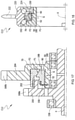
- the clutch C10 includes a bearing part comprised of a guide member 50 with an outer raceway, an outer ring 190 with an inner raceway, and a group of rollers 192; and an overrunning clutch part comprised of a guide member 50, an intermediate member 90 and a friction member 70.
- the sectional cone type traction friction mechanism F1 and force transfer mechanism F2 is composed by assembly of the friction member 70, which is preferably attached to the inner circumferential surface of the outer ring 190 by a straight spline, with the intermediate member 90 and an outer sectional cone flange 66 on the outer circumferential surface of the guide member 50 respectively, to improve the torque transfer ability and increase the value of ⁇ .
- the helical guide teeth of the rotation orientation mechanism G are provided on the inner circumferential surface of the intermediate member 90 and on the outer circumferential surface of the guide member 50 respectively.
- the spring 150 is preferably an axial compressive plate shape torsion spring, wherein one end of the spring is inserted into the corresponding axial hole on the outer end surface of the intermediate member 90, and the other end is inserted into the corresponding hole on the outer circumferential surface of the guide member 50.
- the clutch C10 is apparently capable to replace the CSK type one-way clutch, and possesses greater bearing capacity.
- the guide member 50 may be directly formed on the transmission shaft, the friction member 70 may be directly formed on the outer ring 190, and a needle bearing instead of the ball bearing is added between the intermediate member 90 and the outer ring 190.
- the inner diameter of the overrunning clutch without an inner ring may be as less as 3mm as in the prior art, and the bearing capacity is obviously larger than 0.2 newton meter of prior art depending on line contact friction mechanism. It is easy to be understood that, the modified clutch without an inner ring may be achieved by radially overturn the clutch C10 entirely.
- the bag shape package housing shown in Figure 6-7 is more suitable to be used in minimized and small type overrunning clutch.
- the outer ring 190 is used as a bag shape friction member 70, and the clutch C3 is provided at the right half of the clutch C10.
- Figure 16 shows a guide roller embodiment C11 of a hydrokinetic torque converter incorporating the present invention.
- a guide wheel 196 integrated with the guide member 50 of the embodiment C11 is rotatablely fastened at the outer circumferential surface of the static ring 194 by a clip ring 184.
- the traction friction mechanism F1 and force transfer mechanism F2 is composed by assembly of the friction member 70, which is circumferentially attached at the outer circumferential surface of the static ring 194 by a spline, with the inner frusto-conic surface of the intermediate member 90 and inner end surface of the guide member 50 respectively.
- the helical guide teeth of the rotation orientation mechanism G are provided on the outer circumferential surface of the intermediate member 90 and on the inner circumferential surface of the guide member 50 respectively.
- the embodiment C12 is a two-shaft assembly of a loader transmission incorporating the present invention.
- a gearwheel 204 with teeth 168b is integrated with the guide member 50, and is radially positioned at a shaft, which extends toward one end, of a pinion 200 by a bearing.
- the traction friction mechanism F1 and force transfer mechanism F2 is composed by assembly of the friction member 70, which is circumferentially attached on the annular end surface flange 202 of the pinion 200 having teeth 168a by a spline, with the outer frusto-conic surface of the intermediate member 90 and the inner end surface of the end surface circumferential groove of the gearwheel 204 respectively.
- the helical guide teeth of the rotation orientation mechanism G are provided on the inner circumferential surface of the intermediate member 90 and on the outer circumferential surface of the guide member 50 respectively.
- FIG 18 shows a flywheel embodiment C13 of a bicycle or an electric bicycle.
- a flywheel outer ring 220 with sprockets 222 is rotatablely fixed at the guide member 50 serving as the inner ring of the flywheel by two sets of balls 192 and a flywheel cap 224.
- the friction member 70 is preferably circumferentially fixed on the inner circumferential surface of the outer ring by a spline connection for not bringing axial pressure on the balls 192.
- the structure of the overrunning clutch is similar as that shown in Figure 15 , except that the rotate friction surface of the force transfer friction mechanism F2 is changed to an end flat surface, and the spring 150 is changed to a wave shape spring.
- the engagement idle stroke or slippage angle of above flywheel is approximate to zero, and the bearing capacity is not smaller that the ratchet flywheel.
- Figure 19 shows a wheel hub embodiment C14 of an electric bicycle utilizing the present invention.
- a hub housing 206 revolving about axis X and rigidly integrated with a guide member 50 and a force limiting member 180 is radially fastened on a hub shaft 216 by a bearing 158.
- a decelerator base mounting 214 is installed within the hub housing 206.
- a gear 210 and a shaft gear 212 integrated together are mounted in the decelerator base mounting 214.
- the hollow output shaft gear 208 which revolves about the axis X, of motor drives the gear 210 engaged with the shaft gear 208, and then drives the friction member 70 engaged with the gear 212 through the gear 212.
- the friction member 70 encircles the guide member 50 with a clearance, and then is assembled with inner end surface of a force limiting end 188 and the outer end surface of the intermediate member 90 to form a force transfer friction mechanism F2 and a traction friction mechanism F1 respectively.
- the helical guide teeth of the rotation guide mechanism G are positioned at the inner circumferential surface of the intermediate member 90 and the outer circumferential surface of the hollow shaft.
- Figure 20 shows an embodiment of an electric actuating overrunning clutch C15 of a motorcycle adopting the present invention.
- the guide member 50 which is an annular end surface flange, is rigidly integrated at one end of an actuating gear plate 198.
- the actuating gear plate 198 rotatablely encircles the tubular body 76 with clearance.
- the actuating gear plate 198 and the intermediate member 90 are frictionally connected to the friction member 70 from two sides respectively.
- a plate shape or an axial compressive plate shape torsion spring 150 is further used to restrict the intermediate member 90 in axial direction.
- the friction member 70 of the clutch C3 may be used as the gear plate 198 directly.
- the overrunning clutch relating to spatial mechanism in the prior art includes at most the SSS auto-synchronous clutch with at least 50 years history, and the guided jaw overrunning clutch disclosed in the patent application CN101672335A submitted by the present applicant.
- long time ago from invention of helical water carrying equipment by Archimedes until now, the transmission guide theory has been studied and applied for 2230 years, the history of manufacturing helical/screw with modem machinery is longer than 230 years, and they are used everywhere. Therefore, it is impossible for people not to practice better technical solution in any application condition or any technical innovation if there is relevant technical suggestion or hint.
- the present invention not only has the potential to replace the current techniques, but also has the potential to expand its depth and width of application in larger torque/power, higher rotating speed and transformation frequency, larger or smaller dimension, and more mechanical transmission field.
- the present invention is capable to efficiently resolve any corresponding problems in the prior art, no matter in large scale or miniature transmission, precise graduation or high speed/high frequency transmission, or any type of decelerating transmission, positioning hinge and spanner.
- the present invention may be applied in the actuating mechanism of self-actuate prime mover including the engine of airplane, thus the constant connection of the actuator with the prime mover, overload protection and fast actuating, complete removal of the unnecessary mechanism including the electromagnetic switch can be achieved preferably.
- the arrangement of the one-way overrunning clutch according to the present invention between the output shaft and the base of an internal-combustion engine may economically and reliably realize the purpose of preventing the reverse rotation of the internal-combustion engine.
- all the effort and cost in preventing the system or people from hurting by the reverse rotation may be avoided in the simplest way.
- all the effort and cost in rotation angle measurement for removing the effect of reverse rotation to ensure the proper working condition of the electric ejecting system of an internal-combustion engine may be avoided.
Claims (18)
- Roue libre à friction en forme de coin spatial (C1-C10), comprenant :au moins un mécanisme de friction et de traction (F1) axialement en prise tournant autour d'un axe, ledit mécanisme de friction et de traction (F1) comprenant au moins un élément intermédiaire (90) et un élément de friction (70) tournant autour dudit axe et pourvus d'une surface de friction et de traction (72), l'élément intermédiaire (90) et l'élément de friction (70) étant en butée l'un contre l'autre dans la direction axiale pour former au moins une paire de friction et de traction pour transmettre un couple de friction et de traction entre eux ;au moins un mécanisme de guidage de rotation (G), qui tourne autour dudit axe et fournit une force de mise en prise audit mécanisme de friction et de traction (F1), le mécanisme de guidage de rotation (G) comprenant ledit élément intermédiaire (90) et un élément de guidage (50) tournant autour dudit axe et pourvu d'une surface de guidage (54) correspondante, l'élément intermédiaire (90) et l'élément de guidage (50) étant en butée l'un contre l'autre dans la direction axiale pour former une paire de friction et de guidage ; caractérisée en ce que :un angle d'attaque λ à la position de butée de la paire de friction et de guidage est supérieur à zéro et inférieur ou égal à ξ, c'est-à-dire 0 < λ ≤ ξ, dans la plage de λ, une tendance à la rotation de l'élément de guidage (50) par rapport à l'élément de friction (70) le long de deux directions circonférentielles opposées pouvant amener la roue libre (C1-C10) à être automatiquement amenée dans une situation en prise pour transmettre le couple et à sortir automatiquement de la situation en prise pour tourner librement respectivement au moyen du couple de friction et de traction, ξ étant la valeur maximale de l'angle d'attaque λ qui permet à la paire de friction et de guidage formée à la position de butée d'être autoverrouillée circonférentiellement.
- Roue libre selon la revendication 1, caractérisée en ce que la roue libre (C1-C10) comprend deux mécanismes de friction (F1, F2), chacun étant doté d'une force de mise en prise axiale par le mécanisme de guidage de rotation (G) et tournant autour de l'axe, l'un des deux mécanismes de friction est le mécanisme de friction et de traction (F1), l'autre des deux mécanismes de friction est un mécanisme de friction et de transmission de force (F2) intégré au moins de manière non rotative avec l'élément de guidage (50) et l'élément de friction (70) respectivement, ou un autre mécanisme de friction et de traction (F1).
- Roue libre selon la revendication 2, caractérisée en ce que ledit angle d'attaque λ est supérieur à ζ, c'est-à-dire ζ < λ ≤ ξ, ζ étant la valeur minimale de l'angle d'attaque λ qui permet à la paire de friction et de guidage d'être autoverrouillée circonférentiellement, et également la valeur maximale de l'angle d'attaque λ qui permet à la paire de friction et de traction d'être autoverrouillée circonférentiellement, et la signification de ξ est la même que ci-dessus.
- Roue libre selon la revendication 2, caractérisée en ce que lorsque ζ > 0, ledit angle d'attaque λ est inférieur ou égal à ζ, c'est-à-dire 0 < λ ≤ ζ, ζ étant la valeur minimale de l'angle d'attaque λ qui permet à la paire de friction et de guidage d'être autoverrouillée circonférentiellement.
- Roue libre selon la revendication 2, caractérisée en ce que :
elle comprend en outre au moins un élément de limitation de force (180) ; au plus l'un dudit élément de guidage (50), dudit élément intermédiaire (90) et dudit élément de friction (70) est un ensemble à fermeture par force incorporant ledit élément de limitation de force (180) au moyen d'une liaison fixe de sorte à établir une liaison de butée à fermeture par force axiale entre eux. - Roue libre selon l'une quelconque des revendications 1 à 5, caractérisée en ce que :ledit mécanisme de guidage de rotation (G) a une fonction de guidage de rotation par rapport à deux directions circonférentielles différentes, et ledit élément de guidage (50) a ladite surface de guidage (54) par rapport aux deux directions circonférentielles différentes ; etelle comprend en outre un mécanisme d'orientation, qui restreint fonctionnellement l'élément intermédiaire (90) pour qu'il se trouve dans au moins deux zones circonférentielles différentes par rapport audit élément de guidage (50) de sorte à permettre à l'élément intermédiaire (90) de venir en prise circonférentiellement dans une direction de rotation relative de l'élément de guidage (50), et de définir en outre la direction circonférentielle correspondant à la rotation de guidage du mécanisme de guidage de rotation (G).
- Roue libre selon la revendication 6, caractérisée en ce que ledit mécanisme d'orientation (D) est un mécanisme de mise en prise à goupille-fente comprenant au moins une saillie (124) et au moins un évidement, l'au moins une saillie (124) et l'au moins un évidement étant respectivement situés sur l'un de l'élément intermédiaire (90) et d'un élément de rotation fixé circonférentiellement avec l'élément intermédiaire (90), et l'un de l'élément de guidage (50) et d'un élément de rotation fixé circonférentiellement avec l'élément de guidage (50).
- Roue libre selon la revendication 6, caractérisée en ce qu'elle comprend en outre un mécanisme d'actionnement pour changer l'état d'orientation du mécanisme d'orientation (D).
- Roue libre selon l'une quelconque des revendications 1 à 5, caractérisée en ce qu'elle comprend en outre un mécanisme de maintien élastique ayant au moins un élément élastique pour permettre constamment audit élément intermédiaire (90) et audit élément de friction (70) d'être en liaison de friction au moins indirecte.
- Roue libre selon l'une quelconque des revendications 1 à 5, caractérisée en ce que, la surface de guidage (54) de l'élément de guidage (50) est un flanc de dent hélicoïdale, ledit flanc de dent hélicoïdale étant situé sur une surface comprenant une surface d'extrémité, une surface circonférentielle interne et une surface circonférentielle externe de l'élément de guidage (50) ; un angle inclus entre le flanc de dent hélicoïdale et l'axe étant supérieur à 0° et inférieur à 180° dans le plan axial.
- Roue libre selon la revendication 10, caractérisée en ce que : ledit élément intermédiaire (90) est un élément annulaire formé autour dudit axe et ayant une surface de friction tournante (104) correspondante et une surface de guidage (94), la surface de guidage (94) étant un flanc de dent hélicoïdale ayant une configuration complémentaire avec la surface de guidage (54) de l'élément de guidage (50), et étant située de manière correspondante sur l'une de la surface d'extrémité, de la surface circonférentielle externe (108) et de la surface circonférentielle interne (106) de l'élément intermédiaire (90).
- Roue libre selon l'une quelconque des revendications 1 à 5, caractérisée en ce que :
l'un dudit élément de guidage (50), dudit élément intermédiaire (90), dudit élément de friction (70) et dudit élément de limitation de force (180) est un élément annulaire en forme de sac, dont une surface circonférentielle interne est pourvue d'une demi-structure annulaire circonférentielle (78) et d'un trou traversant (82) communiquant de la rainure (78) à une surface circonférentielle externe de l'élément annulaire en forme de sac. - Roue libre selon la revendication 10, caractérisée en ce que : les flancs de dent hélicoïdale sont respectivement situés sur la surface circonférentielle interne et la surface circonférentielle opposée l'une à l'autre de l'élément de guidage (50) et de l'élément intermédiaire (90), l'élément de guidage (50) étant pourvu d'une partie d'extrémité de limitation de force (188).
- Roue libre selon la revendication 5, caractérisée en ce que : ledit élément de limitation de force (180) est un logement en forme de coupe avec un trou circulaire central.
- Roue libre selon la revendication 5, caractérisée en ce que : ledit ensemble à fermeture par force comprend deux logements semi-circulaires (160) et deux colliers annulaires (170, 172) étant au moins sensiblement symétriques le long de la direction radiale, les formes des deux logements semi-circulaires (160) sont combinées de sorte que le composant combiné formé par la jonction radiale des deux logements semi-circulaires (160) soit pourvu d'un trou circulaire central autour de l'axe et d'une rainure circonférentielle autour de l'axe et disposé sur une surface circonférentielle interne du trou circulaire central, lesdits deux colliers annulaires (170, 172) étant disposés sur une surface circonférentielle externe d'une partie centrale ou d'une bride de surface d'extrémité externe du composant combiné pour fixer ledit composant combiné.
- Roue libre selon l'une quelconque des revendications 2 à 5, caractérisée en ce que : au moins une des surfaces de friction (72, 74) respectives d'au moins un dudit mécanisme de friction et de traction (F1) et dudit mécanisme de transmission de force (F2) est une surface tronconique avec un angle semi-conique supérieur à 0° et inférieur à 180°.
- Roue libre selon l'une quelconque des revendications 1 à 5, caractérisée en ce que : le mécanisme de friction et de traction est un mécanisme de friction (F1) ayant des pièces de friction multiples, parmi lesquelles deux ensembles de pièces de friction entrelacées axialement, chacun comprenant au moins une pièce de friction, sont fixés circonférentiellement à l'élément de friction (70) et à l'élément intermédiaire (90) respectivement.
- Roue libre selon l'une quelconque des revendications 2 à 5, caractérisée en ce que : le mécanisme de transmission de force (F2) est un mécanisme de friction ayant des pièces de friction multiples, parmi lesquelles deux ensembles de pièces de friction entrelacées axialement, chacun comprenant au moins une pièce de friction, sont fixés circonférentiellement à l'élément de friction (70) et à l'élément de guidage (50) respectivement.
Applications Claiming Priority (2)
| Application Number | Priority Date | Filing Date | Title |
|---|---|---|---|
| CN200910158647 | 2009-06-29 | ||
| PCT/CN2010/074619 WO2011000300A1 (fr) | 2009-06-29 | 2010-06-28 | Roue libre à friction en forme de coin spatial |
Publications (3)
| Publication Number | Publication Date |
|---|---|
| EP2450589A1 EP2450589A1 (fr) | 2012-05-09 |
| EP2450589A4 EP2450589A4 (fr) | 2016-03-16 |
| EP2450589B1 true EP2450589B1 (fr) | 2022-03-23 |
Family
ID=43389852
Family Applications (1)
| Application Number | Title | Priority Date | Filing Date |
|---|---|---|---|
| EP10793595.9A Active EP2450589B1 (fr) | 2009-06-29 | 2010-06-28 | Roue libre à friction en forme de coin spatial |
Country Status (5)
| Country | Link |
|---|---|
| US (1) | US9476465B2 (fr) |
| EP (1) | EP2450589B1 (fr) |
| JP (1) | JP5679469B2 (fr) |
| CN (1) | CN101936346B (fr) |
| WO (1) | WO2011000300A1 (fr) |
Families Citing this family (39)
| Publication number | Priority date | Publication date | Assignee | Title |
|---|---|---|---|---|
| CN102537025B (zh) * | 2010-12-30 | 2016-04-13 | 洪涛 | 空间楔合式无级定位铰链 |
| JP5803015B2 (ja) * | 2011-08-31 | 2015-11-04 | Jukiオートメーションシステムズ株式会社 | 搬送装置、処理装置及び搬送方法 |
| CN102748454A (zh) * | 2012-07-03 | 2012-10-24 | 洪涛 | 具有空间楔合式摩擦连接器的液力自动变速器和双离合器自动变速器 |
| CN103527748B (zh) * | 2012-07-03 | 2018-01-09 | 洪涛 | 空间楔合式多槽传动轮和具有该传动轮的提升设备 |
| CN102777512A (zh) * | 2012-07-03 | 2012-11-14 | 洪涛 | 可快速动作的空间楔合式离心离合器、具有该离合器的双离合器自动变速器及其操纵方法 |
| CN102758861A (zh) * | 2012-07-03 | 2012-10-31 | 洪涛 | 柔性接合的自控型空间楔合式摩擦连接器 |
| CN103527687B (zh) * | 2012-07-03 | 2018-06-22 | 洪涛 | 空间楔合式电控离合器 |
| CN102758860B (zh) | 2012-07-27 | 2015-04-15 | 重庆大易用机械有限公司 | 锥形面摩擦式超越离合器 |
| CN102758859B (zh) * | 2012-07-27 | 2015-09-09 | 重庆大易用机械有限公司 | 摩擦式超越离合器 |
| DE102012020472A1 (de) * | 2012-10-18 | 2014-04-24 | Sram Deutschland Gmbh | Freilaufnabe für ein Fahrrad |
| CN102927157B (zh) * | 2012-11-14 | 2015-06-10 | 重庆大易用机械有限公司 | 一种具有缓冲功能的单向传动装置 |
| WO2014127739A1 (fr) * | 2013-02-22 | 2014-08-28 | Hong Tao | Embrayage à roue libre de type à écartement oblique, accouplement, articulation et roue d'entraînement |
| CN103244578B (zh) * | 2013-05-15 | 2016-06-22 | 中国航空动力机械研究所 | 超越离合器 |
| CN103557243A (zh) * | 2013-10-13 | 2014-02-05 | 洪涛 | 易于解楔或解楔转矩等于零的空间楔合式摩擦超越离合器 |
| DE102013019649A1 (de) * | 2013-11-22 | 2015-05-28 | Laudenbach Formtechnik GmbH & Co. KG | Vollflächenfreilauf |
| JP5959556B2 (ja) * | 2014-03-12 | 2016-08-02 | 三菱電機株式会社 | エンジン始動装置 |
| CN103925311B (zh) * | 2014-03-18 | 2016-06-01 | 龙口中宇热管理系统科技有限公司 | 单向离合器 |
| KR101586060B1 (ko) * | 2014-04-10 | 2016-01-15 | 백영구 | 무단변속기 |
| DE102014108087A1 (de) | 2014-06-06 | 2015-12-17 | tune U. Fahl e.K. | Unidirektionale Drehmoment-Kupplung und Verfahren dazu |
| CN104963963B (zh) * | 2014-06-11 | 2018-08-28 | 洪涛 | 具有大楔角的空间楔合式多槽传动轮以及包括该传动轮的多绳摩擦式提升设备 |
| JP5955362B2 (ja) * | 2014-09-09 | 2016-07-20 | 三菱電機株式会社 | エンジン始動装置 |
| JP6021991B1 (ja) * | 2015-04-23 | 2016-11-09 | 三菱電機株式会社 | エンジン始動装置 |
| CN105299207A (zh) * | 2015-11-16 | 2016-02-03 | 广西恒达电机科技有限公司 | 电机实验用启动脱档装置 |
| US10006501B2 (en) | 2015-12-09 | 2018-06-26 | Schaeffler Technologies AG & Co. KG | Clutch actuation device |
| JP2017176111A (ja) * | 2016-03-31 | 2017-10-05 | グローブライド株式会社 | 魚釣用リール |
| JP2017221112A (ja) * | 2016-06-13 | 2017-12-21 | 株式会社東和電機製作所 | 一本釣り機 |
| JP6715512B2 (ja) * | 2016-06-15 | 2020-07-01 | 株式会社東和電機製作所 | 釣り機及びその制御方法 |
| JP6184560B1 (ja) * | 2016-07-15 | 2017-08-23 | 三菱電機株式会社 | スタータ、及びスタータの制御方法 |
| DE112017003875B4 (de) * | 2016-08-02 | 2021-07-22 | Mitsubishi Electric Corporation | Drehmoment-Begrenzungsmechanismus, Antriebseinrichtung, und Robotervorrichtung |
| JP6349004B1 (ja) * | 2017-03-28 | 2018-06-27 | オリジン電気株式会社 | トルクリミッタ |
| DE102017212060A1 (de) * | 2017-07-14 | 2019-01-17 | Bayerische Motoren Werke Aktiengesellschaft | Kopplungseinrichtung |
| US10948056B2 (en) * | 2017-12-23 | 2021-03-16 | Continental Automotive Systems, Inc. | Elevation mechanism for a central input selector knob |
| FR3078124B1 (fr) * | 2018-02-16 | 2020-02-28 | Valeo Materiaux De Friction | Garniture de friction pour embrayage et disque de friction pour embrayage la comportant |
| CN110118229B (zh) * | 2019-05-16 | 2021-06-11 | 海盐瑞扬五金有限公司 | 一种旋转轴体之间的单向式连接装置 |
| KR102270671B1 (ko) * | 2019-11-07 | 2021-06-28 | 주식회사 카펙발레오 | 원웨이 클러치 및 이를 구비하는 토크 컨버터 |
| CN111579373B (zh) * | 2020-05-29 | 2021-04-16 | 浙江礼显试验仪器制造有限公司 | 测量抗压强度试验机 |
| CN111911556B (zh) * | 2020-07-22 | 2021-10-08 | 淮阴工学院 | 一种双向传动转换装置及其传动方法 |
| IT202100003905A1 (it) * | 2021-02-19 | 2021-05-19 | Mpn S R L | Freno di emergenza |
| CN113833786B (zh) * | 2021-10-15 | 2024-01-30 | 浙江天元科技股份有限公司 | 盘式制动器中间隙自调机构的主调总成 |
Family Cites Families (24)
| Publication number | Priority date | Publication date | Assignee | Title |
|---|---|---|---|---|
| GB190412891A (en) * | 1904-06-07 | 1905-05-18 | Thomas Spencer Miller | Improvements in Clutches |
| GB195307A (en) * | 1922-06-08 | 1923-03-29 | Siemens Schuckertwerke Gmbh | Improvements in or relating to clutches |
| GB463608A (en) * | 1936-08-13 | 1937-04-02 | Schuler L Ag | Improvements in or relating to friction clutches |
| DE2233838A1 (de) * | 1972-07-10 | 1974-01-31 | Bosch Gmbh Robert | Andrehvorrichtung fuer brennkraftmaschinen |
| US4462272A (en) * | 1981-08-19 | 1984-07-31 | Rockwell International Corporation | Limited slip differential |
| DE3323995A1 (de) * | 1983-07-02 | 1985-01-10 | Fichtel & Sachs Ag, 8720 Schweinfurt | Gedrueckte membranfederkupplung mit selbsttaetigem verschleissausgleich im bereich des kippkreises |
| CN85107370B (zh) * | 1985-09-20 | 1988-08-17 | 梁信生 | 可操纵的摩擦角自锁离合器 |
| DE3836552A1 (de) * | 1987-10-31 | 1989-05-11 | Zahnradfabrik Friedrichshafen | Differentialgetriebe mit selbsttaetiger sperrkupplung |
| JPH03213751A (ja) * | 1990-01-17 | 1991-09-19 | Tochigi Fuji Ind Co Ltd | 差動制限装置 |
| DE69211669T2 (de) * | 1991-12-28 | 1996-12-12 | Itoh Electric Co Ltd | Antriebskraft-Übertragungsvorrichtung |
| CA2094555C (fr) * | 1993-01-11 | 1999-08-03 | Howard Raymond Sommerfeld | Embrayage a friction a angle variable pour dispositif de traction |
| CN2212681Y (zh) * | 1993-08-15 | 1995-11-15 | 高一知 | 离心楔块超越离合器 |
| CN2175321Y (zh) * | 1993-09-03 | 1994-08-24 | 孙永春 | 摩擦式单向离合器 |
| JPH08120652A (ja) * | 1994-10-19 | 1996-05-14 | Hokoku Kogyo Co Ltd | 水門開閉装置のセルフロック機構 |
| JP3525711B2 (ja) | 1997-11-29 | 2004-05-10 | 富士ゼロックス株式会社 | 画像形成装置 |
| JP4013384B2 (ja) * | 1999-02-05 | 2007-11-28 | 株式会社ジェイテクト | 一方向クラッチ付きプーリユニット |
| CN1103412C (zh) | 1999-07-04 | 2003-03-19 | 石奇文 | 全自动锥面滑块螺旋驱动轮式机动车滑行器 |
| JP4023049B2 (ja) * | 1999-10-14 | 2007-12-19 | 株式会社ジェイテクト | クラッチ装置 |
| CN2479288Y (zh) | 2001-06-15 | 2002-02-27 | 曲秀全 | 锥盘摩擦单向超越离合器 |
| JP2006038183A (ja) * | 2004-07-30 | 2006-02-09 | Koyo Seiko Co Ltd | 動力伝達装置 |
| CN2728825Y (zh) | 2004-08-05 | 2005-09-28 | 贾政 | 全自动机动车节能滑行器 |
| CN100582517C (zh) | 2007-09-18 | 2010-01-20 | 洪涛 | 压合式牙嵌超越离合器 |
| CN101672335B (zh) | 2008-09-08 | 2015-08-26 | 洪涛 | 导向式牙嵌超越离合器 |
| CN201747821U (zh) * | 2010-04-20 | 2011-02-16 | 洪涛 | 空间楔合式摩擦超越离合器 |
-
2010
- 2010-06-28 JP JP2012516503A patent/JP5679469B2/ja active Active
- 2010-06-28 WO PCT/CN2010/074619 patent/WO2011000300A1/fr active Application Filing
- 2010-06-28 EP EP10793595.9A patent/EP2450589B1/fr active Active
- 2010-06-28 CN CN201010222712XA patent/CN101936346B/zh active Active
- 2010-06-28 US US13/381,262 patent/US9476465B2/en active Active
Also Published As
| Publication number | Publication date |
|---|---|
| WO2011000300A1 (fr) | 2011-01-06 |
| CN101936346B (zh) | 2013-01-02 |
| JP5679469B2 (ja) | 2015-03-04 |
| EP2450589A4 (fr) | 2016-03-16 |
| US20120103743A1 (en) | 2012-05-03 |
| US9476465B2 (en) | 2016-10-25 |
| EP2450589A1 (fr) | 2012-05-09 |
| CN101936346A (zh) | 2011-01-05 |
| JP2012531562A (ja) | 2012-12-10 |
Similar Documents
| Publication | Publication Date | Title |
|---|---|---|
| EP2450589B1 (fr) | Roue libre à friction en forme de coin spatial | |
| JP2012531562A5 (fr) | ||
| EP3129671B1 (fr) | Ensemble de poulie à mécanisme de découplage orienté radialement | |
| US8240445B2 (en) | Multiplate clutch and motor vehicle having the same | |
| CN201747821U (zh) | 空间楔合式摩擦超越离合器 | |
| US20100009796A1 (en) | Cam damped pulley for rotary devices | |
| US20050000775A1 (en) | Manual/automatic pressure control mechanism for centrifugal clutch | |
| AU2012352309A1 (en) | Pulley assembly with a decoupling mechanism | |
| WO2005124178A2 (fr) | Embrayage centrifuge et ensemble de montage de couvercle pour cet embrayage | |
| US20130345004A1 (en) | Accessory drive decoupler | |
| JP2008057784A (ja) | 楔式一方向クラッチ | |
| WO2009050066A1 (fr) | Système de transmission pour un véhicule | |
| US6874606B1 (en) | Torque limiting clutch having centrifugally regulated characteristic torque | |
| US4373924A (en) | Torque limiting clutch | |
| CN103277425B (zh) | 双螺旋超越离合器 | |
| CA2497426C (fr) | Mecanisme limiteur de couple | |
| CN102537124B (zh) | 空间楔合式摩擦联轴器和安全离合器 | |
| CN111065844B (zh) | 单个弹簧式的扭转顺应的超越分离器 | |
| EP2707626B1 (fr) | Dispositif de protection amélioré contre le surcouple destiné à un compresseur | |
| CN201041202Y (zh) | 零碰撞弹簧钢球安全离合器 | |
| CN105587797B (zh) | 可降低扭振的空间楔合式超越皮带轮及超越离合器 | |
| EP2522872B1 (fr) | Embrayage à disques avec engagement / dégagement centrifuge | |
| CN201368156Y (zh) | 惯性涨紧离合器 | |
| RU2229042C2 (ru) | Предохранительная фрикционная муфта предельного момента вращения | |
| CN101476606B (zh) | 惯性涨紧离合器 |
Legal Events
| Date | Code | Title | Description |
|---|---|---|---|
| PUAI | Public reference made under article 153(3) epc to a published international application that has entered the european phase |
Free format text: ORIGINAL CODE: 0009012 |
|
| 17P | Request for examination filed |
Effective date: 20120127 |
|
| AK | Designated contracting states |
Kind code of ref document: A1 Designated state(s): AL AT BE BG CH CY CZ DE DK EE ES FI FR GB GR HR HU IE IS IT LI LT LU LV MC MK MT NL NO PL PT RO SE SI SK SM TR |
|
| DAX | Request for extension of the european patent (deleted) | ||
| RIC1 | Information provided on ipc code assigned before grant |
Ipc: F16D 41/06 20060101AFI20160204BHEP Ipc: F16D 41/063 20060101ALI20160204BHEP Ipc: F16D 41/061 20060101ALI20160204BHEP Ipc: F16D 41/00 20060101ALI20160204BHEP |
|
| RA4 | Supplementary search report drawn up and despatched (corrected) |
Effective date: 20160211 |
|
| STAA | Information on the status of an ep patent application or granted ep patent |
Free format text: STATUS: EXAMINATION IS IN PROGRESS |
|
| 17Q | First examination report despatched |
Effective date: 20180803 |
|
| GRAP | Despatch of communication of intention to grant a patent |
Free format text: ORIGINAL CODE: EPIDOSNIGR1 |
|
| STAA | Information on the status of an ep patent application or granted ep patent |
Free format text: STATUS: GRANT OF PATENT IS INTENDED |
|
| INTG | Intention to grant announced |
Effective date: 20201120 |
|
| GRAJ | Information related to disapproval of communication of intention to grant by the applicant or resumption of examination proceedings by the epo deleted |
Free format text: ORIGINAL CODE: EPIDOSDIGR1 |
|
| STAA | Information on the status of an ep patent application or granted ep patent |
Free format text: STATUS: EXAMINATION IS IN PROGRESS |
|
| INTC | Intention to grant announced (deleted) | ||
| GRAP | Despatch of communication of intention to grant a patent |
Free format text: ORIGINAL CODE: EPIDOSNIGR1 |
|
| STAA | Information on the status of an ep patent application or granted ep patent |
Free format text: STATUS: GRANT OF PATENT IS INTENDED |
|
| INTG | Intention to grant announced |
Effective date: 20211028 |
|
| GRAS | Grant fee paid |
Free format text: ORIGINAL CODE: EPIDOSNIGR3 |
|
| GRAA | (expected) grant |
Free format text: ORIGINAL CODE: 0009210 |
|
| STAA | Information on the status of an ep patent application or granted ep patent |
Free format text: STATUS: THE PATENT HAS BEEN GRANTED |
|
| AK | Designated contracting states |
Kind code of ref document: B1 Designated state(s): AL AT BE BG CH CY CZ DE DK EE ES FI FR GB GR HR HU IE IS IT LI LT LU LV MC MK MT NL NO PL PT RO SE SI SK SM TR |
|
| REG | Reference to a national code |
Ref country code: GB Ref legal event code: FG4D |
|
| REG | Reference to a national code |
Ref country code: CH Ref legal event code: EP |
|
| REG | Reference to a national code |
Ref country code: IE Ref legal event code: FG4D |
|
| REG | Reference to a national code |
Ref country code: DE Ref legal event code: R096 Ref document number: 602010068130 Country of ref document: DE |
|
| REG | Reference to a national code |
Ref country code: AT Ref legal event code: REF Ref document number: 1477634 Country of ref document: AT Kind code of ref document: T Effective date: 20220415 |
|
| REG | Reference to a national code |
Ref country code: SE Ref legal event code: TRGR |
|
| REG | Reference to a national code |
Ref country code: LT Ref legal event code: MG9D |
|
| REG | Reference to a national code |
Ref country code: NL Ref legal event code: MP Effective date: 20220323 |
|
| PG25 | Lapsed in a contracting state [announced via postgrant information from national office to epo] |
Ref country code: NO Free format text: LAPSE BECAUSE OF FAILURE TO SUBMIT A TRANSLATION OF THE DESCRIPTION OR TO PAY THE FEE WITHIN THE PRESCRIBED TIME-LIMIT Effective date: 20220623 Ref country code: LT Free format text: LAPSE BECAUSE OF FAILURE TO SUBMIT A TRANSLATION OF THE DESCRIPTION OR TO PAY THE FEE WITHIN THE PRESCRIBED TIME-LIMIT Effective date: 20220323 Ref country code: HR Free format text: LAPSE BECAUSE OF FAILURE TO SUBMIT A TRANSLATION OF THE DESCRIPTION OR TO PAY THE FEE WITHIN THE PRESCRIBED TIME-LIMIT Effective date: 20220323 Ref country code: BG Free format text: LAPSE BECAUSE OF FAILURE TO SUBMIT A TRANSLATION OF THE DESCRIPTION OR TO PAY THE FEE WITHIN THE PRESCRIBED TIME-LIMIT Effective date: 20220623 |
|
| REG | Reference to a national code |
Ref country code: AT Ref legal event code: MK05 Ref document number: 1477634 Country of ref document: AT Kind code of ref document: T Effective date: 20220323 |
|
| PG25 | Lapsed in a contracting state [announced via postgrant information from national office to epo] |
Ref country code: LV Free format text: LAPSE BECAUSE OF FAILURE TO SUBMIT A TRANSLATION OF THE DESCRIPTION OR TO PAY THE FEE WITHIN THE PRESCRIBED TIME-LIMIT Effective date: 20220323 Ref country code: GR Free format text: LAPSE BECAUSE OF FAILURE TO SUBMIT A TRANSLATION OF THE DESCRIPTION OR TO PAY THE FEE WITHIN THE PRESCRIBED TIME-LIMIT Effective date: 20220624 Ref country code: FI Free format text: LAPSE BECAUSE OF FAILURE TO SUBMIT A TRANSLATION OF THE DESCRIPTION OR TO PAY THE FEE WITHIN THE PRESCRIBED TIME-LIMIT Effective date: 20220323 |
|
| PG25 | Lapsed in a contracting state [announced via postgrant information from national office to epo] |
Ref country code: NL Free format text: LAPSE BECAUSE OF FAILURE TO SUBMIT A TRANSLATION OF THE DESCRIPTION OR TO PAY THE FEE WITHIN THE PRESCRIBED TIME-LIMIT Effective date: 20220323 |
|
| PG25 | Lapsed in a contracting state [announced via postgrant information from national office to epo] |
Ref country code: SM Free format text: LAPSE BECAUSE OF FAILURE TO SUBMIT A TRANSLATION OF THE DESCRIPTION OR TO PAY THE FEE WITHIN THE PRESCRIBED TIME-LIMIT Effective date: 20220323 Ref country code: SK Free format text: LAPSE BECAUSE OF FAILURE TO SUBMIT A TRANSLATION OF THE DESCRIPTION OR TO PAY THE FEE WITHIN THE PRESCRIBED TIME-LIMIT Effective date: 20220323 Ref country code: RO Free format text: LAPSE BECAUSE OF FAILURE TO SUBMIT A TRANSLATION OF THE DESCRIPTION OR TO PAY THE FEE WITHIN THE PRESCRIBED TIME-LIMIT Effective date: 20220323 Ref country code: PT Free format text: LAPSE BECAUSE OF FAILURE TO SUBMIT A TRANSLATION OF THE DESCRIPTION OR TO PAY THE FEE WITHIN THE PRESCRIBED TIME-LIMIT Effective date: 20220725 Ref country code: ES Free format text: LAPSE BECAUSE OF FAILURE TO SUBMIT A TRANSLATION OF THE DESCRIPTION OR TO PAY THE FEE WITHIN THE PRESCRIBED TIME-LIMIT Effective date: 20220323 Ref country code: EE Free format text: LAPSE BECAUSE OF FAILURE TO SUBMIT A TRANSLATION OF THE DESCRIPTION OR TO PAY THE FEE WITHIN THE PRESCRIBED TIME-LIMIT Effective date: 20220323 Ref country code: CZ Free format text: LAPSE BECAUSE OF FAILURE TO SUBMIT A TRANSLATION OF THE DESCRIPTION OR TO PAY THE FEE WITHIN THE PRESCRIBED TIME-LIMIT Effective date: 20220323 Ref country code: AT Free format text: LAPSE BECAUSE OF FAILURE TO SUBMIT A TRANSLATION OF THE DESCRIPTION OR TO PAY THE FEE WITHIN THE PRESCRIBED TIME-LIMIT Effective date: 20220323 |
|
| PG25 | Lapsed in a contracting state [announced via postgrant information from national office to epo] |
Ref country code: PL Free format text: LAPSE BECAUSE OF FAILURE TO SUBMIT A TRANSLATION OF THE DESCRIPTION OR TO PAY THE FEE WITHIN THE PRESCRIBED TIME-LIMIT Effective date: 20220323 Ref country code: IS Free format text: LAPSE BECAUSE OF FAILURE TO SUBMIT A TRANSLATION OF THE DESCRIPTION OR TO PAY THE FEE WITHIN THE PRESCRIBED TIME-LIMIT Effective date: 20220723 Ref country code: AL Free format text: LAPSE BECAUSE OF FAILURE TO SUBMIT A TRANSLATION OF THE DESCRIPTION OR TO PAY THE FEE WITHIN THE PRESCRIBED TIME-LIMIT Effective date: 20220323 |
|
| REG | Reference to a national code |
Ref country code: DE Ref legal event code: R097 Ref document number: 602010068130 Country of ref document: DE |
|
| PLBE | No opposition filed within time limit |
Free format text: ORIGINAL CODE: 0009261 |
|
| STAA | Information on the status of an ep patent application or granted ep patent |
Free format text: STATUS: NO OPPOSITION FILED WITHIN TIME LIMIT |
|
| PG25 | Lapsed in a contracting state [announced via postgrant information from national office to epo] |
Ref country code: MC Free format text: LAPSE BECAUSE OF FAILURE TO SUBMIT A TRANSLATION OF THE DESCRIPTION OR TO PAY THE FEE WITHIN THE PRESCRIBED TIME-LIMIT Effective date: 20220323 Ref country code: DK Free format text: LAPSE BECAUSE OF FAILURE TO SUBMIT A TRANSLATION OF THE DESCRIPTION OR TO PAY THE FEE WITHIN THE PRESCRIBED TIME-LIMIT Effective date: 20220323 |
|
| REG | Reference to a national code |
Ref country code: CH Ref legal event code: PL |
|
| REG | Reference to a national code |
Ref country code: BE Ref legal event code: MM Effective date: 20220630 |
|
| 26N | No opposition filed |
Effective date: 20230102 |
|
| PG25 | Lapsed in a contracting state [announced via postgrant information from national office to epo] |
Ref country code: LU Free format text: LAPSE BECAUSE OF NON-PAYMENT OF DUE FEES Effective date: 20220628 Ref country code: LI Free format text: LAPSE BECAUSE OF NON-PAYMENT OF DUE FEES Effective date: 20220630 Ref country code: IE Free format text: LAPSE BECAUSE OF NON-PAYMENT OF DUE FEES Effective date: 20220628 Ref country code: CH Free format text: LAPSE BECAUSE OF NON-PAYMENT OF DUE FEES Effective date: 20220630 |
|
| PG25 | Lapsed in a contracting state [announced via postgrant information from national office to epo] |
Ref country code: SI Free format text: LAPSE BECAUSE OF FAILURE TO SUBMIT A TRANSLATION OF THE DESCRIPTION OR TO PAY THE FEE WITHIN THE PRESCRIBED TIME-LIMIT Effective date: 20220323 Ref country code: BE Free format text: LAPSE BECAUSE OF NON-PAYMENT OF DUE FEES Effective date: 20220630 |
|
| PGFP | Annual fee paid to national office [announced via postgrant information from national office to epo] |
Ref country code: IT Payment date: 20230612 Year of fee payment: 14 Ref country code: FR Payment date: 20230620 Year of fee payment: 14 Ref country code: DE Payment date: 20230607 Year of fee payment: 14 |
|
| PGFP | Annual fee paid to national office [announced via postgrant information from national office to epo] |
Ref country code: SE Payment date: 20230613 Year of fee payment: 14 |
|
| PGFP | Annual fee paid to national office [announced via postgrant information from national office to epo] |
Ref country code: GB Payment date: 20230608 Year of fee payment: 14 |
|
| PG25 | Lapsed in a contracting state [announced via postgrant information from national office to epo] |
Ref country code: HU Free format text: LAPSE BECAUSE OF FAILURE TO SUBMIT A TRANSLATION OF THE DESCRIPTION OR TO PAY THE FEE WITHIN THE PRESCRIBED TIME-LIMIT; INVALID AB INITIO Effective date: 20100628 |
|
| PG25 | Lapsed in a contracting state [announced via postgrant information from national office to epo] |
Ref country code: MK Free format text: LAPSE BECAUSE OF FAILURE TO SUBMIT A TRANSLATION OF THE DESCRIPTION OR TO PAY THE FEE WITHIN THE PRESCRIBED TIME-LIMIT Effective date: 20220323 Ref country code: CY Free format text: LAPSE BECAUSE OF FAILURE TO SUBMIT A TRANSLATION OF THE DESCRIPTION OR TO PAY THE FEE WITHIN THE PRESCRIBED TIME-LIMIT Effective date: 20220323 |