EP2448663B1 - Vorrichtung zur kontinuierlichen durchführung chemischer reaktionen bei hohen temperaturen - Google Patents
Vorrichtung zur kontinuierlichen durchführung chemischer reaktionen bei hohen temperaturen Download PDFInfo
- Publication number
- EP2448663B1 EP2448663B1 EP10725034.2A EP10725034A EP2448663B1 EP 2448663 B1 EP2448663 B1 EP 2448663B1 EP 10725034 A EP10725034 A EP 10725034A EP 2448663 B1 EP2448663 B1 EP 2448663B1
- Authority
- EP
- European Patent Office
- Prior art keywords
- microwave
- reaction
- reaction mixture
- zone
- temperature
- Prior art date
- Legal status (The legal status is an assumption and is not a legal conclusion. Google has not performed a legal analysis and makes no representation as to the accuracy of the status listed.)
- Expired - Fee Related
Links
Images

Classifications
-
- C—CHEMISTRY; METALLURGY
- C07—ORGANIC CHEMISTRY
- C07C—ACYCLIC OR CARBOCYCLIC COMPOUNDS
- C07C1/00—Preparation of hydrocarbons from one or more compounds, none of them being a hydrocarbon
- C07C1/32—Preparation of hydrocarbons from one or more compounds, none of them being a hydrocarbon starting from compounds containing hetero-atoms other than or in addition to oxygen or halogen
- C07C1/321—Preparation of hydrocarbons from one or more compounds, none of them being a hydrocarbon starting from compounds containing hetero-atoms other than or in addition to oxygen or halogen the hetero-atom being a non-metal atom
-
- B—PERFORMING OPERATIONS; TRANSPORTING
- B01—PHYSICAL OR CHEMICAL PROCESSES OR APPARATUS IN GENERAL
- B01J—CHEMICAL OR PHYSICAL PROCESSES, e.g. CATALYSIS OR COLLOID CHEMISTRY; THEIR RELEVANT APPARATUS
- B01J19/00—Chemical, physical or physico-chemical processes in general; Their relevant apparatus
- B01J19/08—Processes employing the direct application of electric or wave energy, or particle radiation; Apparatus therefor
- B01J19/12—Processes employing the direct application of electric or wave energy, or particle radiation; Apparatus therefor employing electromagnetic waves
- B01J19/122—Incoherent waves
- B01J19/126—Microwaves
-
- C—CHEMISTRY; METALLURGY
- C07—ORGANIC CHEMISTRY
- C07C—ACYCLIC OR CARBOCYCLIC COMPOUNDS
- C07C231/00—Preparation of carboxylic acid amides
- C07C231/02—Preparation of carboxylic acid amides from carboxylic acids or from esters, anhydrides, or halides thereof by reaction with ammonia or amines
-
- C—CHEMISTRY; METALLURGY
- C07—ORGANIC CHEMISTRY
- C07C—ACYCLIC OR CARBOCYCLIC COMPOUNDS
- C07C67/00—Preparation of carboxylic acid esters
- C07C67/08—Preparation of carboxylic acid esters by reacting carboxylic acids or symmetrical anhydrides with the hydroxy or O-metal group of organic compounds
-
- C—CHEMISTRY; METALLURGY
- C07—ORGANIC CHEMISTRY
- C07D—HETEROCYCLIC COMPOUNDS
- C07D307/00—Heterocyclic compounds containing five-membered rings having one oxygen atom as the only ring hetero atom
- C07D307/02—Heterocyclic compounds containing five-membered rings having one oxygen atom as the only ring hetero atom not condensed with other rings
- C07D307/34—Heterocyclic compounds containing five-membered rings having one oxygen atom as the only ring hetero atom not condensed with other rings having two or three double bonds between ring members or between ring members and non-ring members
- C07D307/56—Heterocyclic compounds containing five-membered rings having one oxygen atom as the only ring hetero atom not condensed with other rings having two or three double bonds between ring members or between ring members and non-ring members with hetero atoms or with carbon atoms having three bonds to hetero atoms with at the most one bond to halogen, e.g. ester or nitrile radicals, directly attached to ring carbon atoms
- C07D307/60—Two oxygen atoms, e.g. succinic anhydride
-
- C—CHEMISTRY; METALLURGY
- C08—ORGANIC MACROMOLECULAR COMPOUNDS; THEIR PREPARATION OR CHEMICAL WORKING-UP; COMPOSITIONS BASED THEREON
- C08F—MACROMOLECULAR COMPOUNDS OBTAINED BY REACTIONS ONLY INVOLVING CARBON-TO-CARBON UNSATURATED BONDS
- C08F8/00—Chemical modification by after-treatment
- C08F8/46—Reaction with unsaturated dicarboxylic acids or anhydrides thereof, e.g. maleinisation
-
- H—ELECTRICITY
- H05—ELECTRIC TECHNIQUES NOT OTHERWISE PROVIDED FOR
- H05B—ELECTRIC HEATING; ELECTRIC LIGHT SOURCES NOT OTHERWISE PROVIDED FOR; CIRCUIT ARRANGEMENTS FOR ELECTRIC LIGHT SOURCES, IN GENERAL
- H05B6/00—Heating by electric, magnetic or electromagnetic fields
- H05B6/64—Heating using microwaves
- H05B6/80—Apparatus for specific applications
- H05B6/806—Apparatus for specific applications for laboratory use
-
- B—PERFORMING OPERATIONS; TRANSPORTING
- B01—PHYSICAL OR CHEMICAL PROCESSES OR APPARATUS IN GENERAL
- B01J—CHEMICAL OR PHYSICAL PROCESSES, e.g. CATALYSIS OR COLLOID CHEMISTRY; THEIR RELEVANT APPARATUS
- B01J2219/00—Chemical, physical or physico-chemical processes in general; Their relevant apparatus
- B01J2219/08—Processes employing the direct application of electric or wave energy, or particle radiation; Apparatus therefor
- B01J2219/0871—Heating or cooling of the reactor
-
- B—PERFORMING OPERATIONS; TRANSPORTING
- B01—PHYSICAL OR CHEMICAL PROCESSES OR APPARATUS IN GENERAL
- B01J—CHEMICAL OR PHYSICAL PROCESSES, e.g. CATALYSIS OR COLLOID CHEMISTRY; THEIR RELEVANT APPARATUS
- B01J2219/00—Chemical, physical or physico-chemical processes in general; Their relevant apparatus
- B01J2219/08—Processes employing the direct application of electric or wave energy, or particle radiation; Apparatus therefor
- B01J2219/12—Processes employing electromagnetic waves
- B01J2219/1203—Incoherent waves
- B01J2219/1206—Microwaves
- B01J2219/1209—Features relating to the reactor or vessel
- B01J2219/1221—Features relating to the reactor or vessel the reactor per se
- B01J2219/1224—Form of the reactor
- B01J2219/1227—Reactors comprising tubes with open ends
-
- C—CHEMISTRY; METALLURGY
- C07—ORGANIC CHEMISTRY
- C07C—ACYCLIC OR CARBOCYCLIC COMPOUNDS
- C07C2531/00—Catalysts comprising hydrides, coordination complexes or organic compounds
- C07C2531/16—Catalysts comprising hydrides, coordination complexes or organic compounds containing coordination complexes
- C07C2531/24—Phosphines
-
- C—CHEMISTRY; METALLURGY
- C08—ORGANIC MACROMOLECULAR COMPOUNDS; THEIR PREPARATION OR CHEMICAL WORKING-UP; COMPOSITIONS BASED THEREON
- C08F—MACROMOLECULAR COMPOUNDS OBTAINED BY REACTIONS ONLY INVOLVING CARBON-TO-CARBON UNSATURATED BONDS
- C08F2810/00—Chemical modification of a polymer
- C08F2810/30—Chemical modification of a polymer leading to the formation or introduction of aliphatic or alicyclic unsaturated groups
-
- C—CHEMISTRY; METALLURGY
- C08—ORGANIC MACROMOLECULAR COMPOUNDS; THEIR PREPARATION OR CHEMICAL WORKING-UP; COMPOSITIONS BASED THEREON
- C08F—MACROMOLECULAR COMPOUNDS OBTAINED BY REACTIONS ONLY INVOLVING CARBON-TO-CARBON UNSATURATED BONDS
- C08F2810/00—Chemical modification of a polymer
- C08F2810/40—Chemical modification of a polymer taking place solely at one end or both ends of the polymer backbone, i.e. not in the side or lateral chains
Definitions
- the present invention relates to an apparatus for the continuous performance of chemical reactions at high temperatures and pressure under heating by microwave irradiation on an industrial scale.
- WO-90/03840 discloses a continuous process for performing various chemical reactions in a continuous laboratory microwave reactor.
- the reaction mixture is heated to temperatures of up to 190 ° C. at variable flow rates of up to 1.4 l / h in a multimode microwave oven under pressures of up to 12 bar.
- the reaction product is cooled substantially immediately after passing through the microwave zone.
- the conversions achieved in many cases still show potential for optimization and the efficiency of this method with respect to the microwave absorption of the reaction material is low due to the microwave energy distributed more or less homogeneously in the applicator chamber and not focused on the coil in multimode microwave applicators.
- a large increase in the irradiated microwave power would lead to unwanted plasma discharges here.
- the time-varying spatial inhomogeneities of the microwave field referred to as hot spots, make reliable and reproducible reaction on a large scale impossible.
- EP-A-1 291 077 discloses a microwave reactor in which a liquid in a tube is passed through a microwave waveguide transverse to the propagation direction of the standing electromagnetic wave and in which molecules are activated by dissociation and / or ionization by microwave radiation to subsequently react with another reactant in a reaction space become. Due to the very small irradiation zone on the one hand, the treatable amount of substance is extremely limited and the other low energy input. An up-scaling of this method by increasing the tube cross-section is also contrary to the usually limited to a few millimeters to a few centimeters of penetration of microwaves into the reaction.
- Esveld et al., Chem. Eng. Technol. 23 (2000), 429-435 discloses a continuous process for producing wax esters in which fatty alcohol and fatty acid are esterified solvent-free in the presence of montmorillonite.
- the reaction mixture On a conveyor belt, the reaction mixture is heated by microwave radiation within 5 minutes to reaction temperature and then held for a further 30 minutes to substantially remove the resulting reaction water at this temperature.
- This process performed in an open system, is naturally only applicable to high boiling reactants (and reaction products).
- the reaction mixture is cooled as soon as possible after leaving the irradiation zone as soon as possible, with microwave-assisted reactions carried out continuously in the flow tube, e.g. B. by adiabatic expansion according to WO-04/054707 ,
- WO-2003/041856 teaches continuous flow heating and a method of performing chemical reactions in a system comprising at least one warm-up section with a microwave heater and at least one heating means to maintain the temperature of the process fluid substantially constant.
- WO-2008/043494 teaches a process for the preparation of tertiary amides of alkylphenylcarboxylic acids by reacting at least one secondary amine with at least one alkylphenylcarboxylic acid to form an ammonium salt and subsequently reacting this ammonium salt under microwave irradiation to form the tertiary amide.
- the object of the invention was therefore to provide a device for continuously carrying out chemical reactions on an industrial scale at high temperatures, in which the reaction mixture heated as quickly as possible and without partial overheating to the desired reaction temperature and then maintained at this reaction temperature for a defined period of time and can then be cooled. Furthermore, the device should allow working above the atmospheric pressure, so that all components of the reaction mixture remain in the liquid state. The device should allow a high space-time yield, high energy efficiency and beyond a safe and reproducible work.
- the invention relates to a device for continuously carrying out chemical reactions, comprising a microwave generator, a microwave applicator in which a microwave-transparent tube is located, and an isothermal reaction section, which are arranged such that the reaction mixture in the microwave-transparent tube whose longitudinal axis is in the propagation direction of the Microwave is passed through a acting as a heating zone single-mode microwave applicator in which it is heated by means of microwaves, which are fed from the microwave generator in the microwave applicator to reaction temperature and in the heated and optionally pressurized reaction mixture directly after leaving the Heating zone is converted into an adjoining the heating zone isothermal reaction zone and cooled after leaving the isothermal reaction zone.
- Another object of the invention is a method for continuously performing chemical reactions in which the reaction mixture is guided in a microwave transparent tube whose longitudinal axis is in the propagation direction of the microwaves, through a heating zone in which it is heated to reaction temperature by means of microwaves and in the that heated and optionally pressurized reaction mixture directly after leaving the Heating zone is converted into an adjoining the heating zone isothermal reaction zone and cooled after leaving the isothermal reaction zone.
- the device according to the invention and the method according to the invention are preferably suitable for those reactions which require a certain activation energy. They are particularly suitable for reactions whose activation energy is at least 0.01 kJ / mol, preferably at least 0.1 kJ / mol, for example 1 to 100 kJ / mol. With further preference the device according to the invention and the method according to the invention are suitable for reactions which take place without significant exothermic evolution of heat. Thus, they are particularly suitable for reactions whose heat of reaction ⁇ H is less than -20 kJ / mol and especially less than -10 kJ / mol, for example less than -2 kJ / mol.
- the device according to the invention and the method according to the invention are particularly preferred for endothermic reactions whose heat of reaction ⁇ H is greater than +0.1 kJ / mol and specifically between +1 kJ / mol and +100 kJ / mol, for example between +2 kJ / mol and 70 kJ / mol is.
- reaction mixtures may also contain auxiliaries such as, for example, solvents and / or catalysts for accelerating the reactions.
- Microwaves are electromagnetic waves with a wavelength between 1 cm and 1 m and frequencies between 300 MHz and 30 GHz. This frequency range is suitable in principle for the method according to the invention.
- microwave radiation is used with the frequencies released for industrial, scientific, medical, domestic or similar applications, such as frequencies of 915 MHz, 2.45 GHz, 5.8 GHz or 24.12 GHz.
- the device according to the invention contains, as a microwave-transparent tube, a pressure-resistant, chemically inert tube (heating tube), through which the reaction mixture is exposed to the microwave radiation.
- a pressure-resistant, chemically inert tube heating tube
- single-mode microwave ovens or microwave applicators of various geometries will be used.
- Microwave generator, microwave applicator and microwave-transparent tube are arranged so that the reaction mixture is guided in the microwave-transparent tube through a functioning as a microwave heating microwave applicator in which it is heated to reaction temperature by means of microwaves, which are fed from the microwave generator in the microwave applicator.
- the isothermal reaction zone is arranged in such a way that the heated reaction mixture, which may be under pressure, immediately after leaving the heating zone, passes into the isothermal reaction zone adjoining the heating zone and is cooled after leaving the isothermal reaction zone.
- the heating of the reaction material takes place in a microwave-transparent, straight tube whose longitudinal axis is in the propagation direction of the microwaves of a single-mode microwave applicator.
- the irradiation of the reaction product with microwaves preferably takes place in a microwave-transparent, straight heating tube, which is located within a waveguide connected to a microwave generator.
- the heating tube is aligned axially with the central axis of symmetry of the waveguide.
- the waveguide acting as a microwave applicator is preferably formed as a cavity resonator. Further preferred are the from Reactive material in the waveguide unabsorbed microwaves reflected at its end. Preferably, the length of the cavity resonator is dimensioned so that it forms a standing wave in it. Due to the shape of the microwave applicator as a resonator of the reflection type, a local increase in the electric field strength with the same power supplied by the generator and an increased energy utilization are achieved in the applicator.
- the cavity resonator is preferably operated in the E 01n mode, where n stands for an integer and indicates the number of field maxima of the microwave along the central axis of symmetry of the resonator.
- the electric field is directed toward the central axis of symmetry of the cavity resonator. It has a maximum in the area of the central axis of symmetry and decreases to the lateral surface to the value zero.
- This field configuration is rotationally symmetric about the central axis of symmetry.
- N is preferably an integer from 1 to 200, particularly preferably from 2 to 100, in particular from 3 to 50, especially from 4 to 20, for example three, four, five, six, seven, eight, nine or ten.
- the E 01n mode of the cavity resonator is also referred to in English as TM 01n mode, see for example K. Lange, KH Löcherer, Paperback of High Frequency Technology ", Volume 2, page K21 ff ,
- the irradiation of the microwave energy into the waveguide acting as a microwave applicator can take place via suitably dimensioned holes or slots.
- the irradiation of the reaction product with microwaves takes place in a heating tube which is located in a waveguide with coaxial transition of the microwaves.
- particularly preferred microwave devices are made of a Cavity resonator, a coupling device for coupling a microwave field in the cavity resonator and constructed with one opening on two opposite end walls for passing the reaction tube through the resonator.
- the coupling of the microwaves in the cavity resonator is preferably carried out via a coupling pin, which projects into the cavity resonator.
- the coupling pin is preferably shaped as a preferably metallic inner conductor tube functioning as a coupling antenna.
- this coupling pin protrudes through one of the frontal openings into the cavity resonator.
- the heating tube connects to the inner conductor tube of the coaxial transition and in particular it is guided through its cavity into the cavity resonator.
- the heating tube is aligned axially with a central axis of symmetry of the cavity resonator.
- the cavity resonator preferably each has a central opening on two opposite end walls for passing the heating tube.
- the feeding of the microwaves in the coupling pin or in the acting as a coupling antenna inner conductor tube can be done for example by means of a coaxial connecting cable.
- the microwave field is supplied to the resonator via a waveguide, wherein the protruding from the cavity resonator end of the coupling pin is guided into an opening which is located in the wall of the waveguide in the waveguide and the waveguide takes microwave energy and in the Resonator couples.
- the irradiation of the reaction product with microwaves in a microwave-transparent heating tube which is axially symmetrical in a E 01n round hollow conductor with coaxial transition of the microwaves.
- the heating tube is preferably guided through the cavity of an inner conductor tube acting as a coupling antenna into the cavity resonator.
- Microwave generators such as the magnetron, the klystron and the gyrotron are known in the art.
- the dielectric loss factor tan ⁇ is defined as the ratio of the dielectric loss ⁇ "and the dielectric constant ⁇ .” Examples of tan ⁇ values of different materials are, for example, in D. Bogdal, Microwave-assisted Organic Synthesis, Elsevier 2005 played.
- microwave-transparent and temperature-stable materials are primarily materials based on minerals such as quartz, alumina, sapphire, zirconium oxide, silicon nitride and the like into consideration.
- thermally stable plastics such as in particular fluoropolymers such as Teflon, and engineering plastics such as polypropylene, or polyaryletherketones such as glass fiber reinforced polyetheretherketone (PEEK) are suitable as pipe materials.
- PEEK glass fiber reinforced polyetheretherketone
- suitable for microwave irradiation heating tubes have an inner diameter of one millimeter to about 50 cm, in particular between 2 mm and 35 cm and especially between 5 mm and 15 cm, for example between 10 mm and 7 cm.
- heating pipes are understood to be vessels whose length to diameter ratio is greater than 5, preferably between 10 and 100,000, particularly preferably between 20 and 10,000, for example between 30 and 1,000.
- the length of the heating tube is understood to be the distance of the tube on which the microwave irradiation takes place.
- baffles and / or other mixing elements can be installed.
- particularly suitable E 01 cavity resonators preferably have a diameter which corresponds to at least half the wavelength of the microwave radiation used.
- the diameter of the cavity resonator is preferably 1.0 to 10 times, particularly preferably 1.1 to 5 times, and in particular 2.1 to 2.6 times, the half wavelength of the microwave radiation used.
- the E 01 cavity resonator has a round cross section, which is also referred to as E 01 round waveguide. More preferably, it has a cylindrical shape and especially one circular cylindrical shape.
- the residence time of the reaction material in the heating zone depends on various factors such as the geometry of the heating tube, the radiated microwave energy, the specific microwave absorption of the reaction mixture and the desired reaction temperature.
- the residence time of the reaction mixture in the heating zone is usually less than 30 minutes, preferably between 0.01 second and 15 minutes, more preferably between 0.1 second and 10 minutes and especially between 1 second and 5 minutes, for example between 5 seconds and 2 minutes .
- the intensity (power) of the microwave radiation is adjusted so that the reaction mixture has the desired reaction temperature when leaving the heating zone.
- the microwave power to be radiated into the cavity resonator for carrying out the method according to the invention depends in particular on the desired reaction temperature, but also on the geometry of the heating tube and thus the reaction volume and the flow rate of the reaction mixture through the heating zone.
- the microwave power to be radiated is usually between 200 W and several 100 kW and in particular between 500 W and 100 kW, for example between 1 kW and 70 kW. It can be generated by one or more microwave generators.
- the microwave power is preferably adjusted so that the reaction mixture reaches the desired reaction temperature in as short a time as possible, without, however, causing electrical discharges in the microwave applicator.
- the temperature rise caused by the microwave irradiation is limited to a maximum of 500 ° C., for example by controlling the microwave intensity and / or the flow rate, at least for organic chemistry reactions. For inorganic reactions, higher temperatures can also be set.
- temperatures between 70 and a maximum of 400 ° C in particular at temperatures between 120 and at most 330 ° C and especially between 150 and at most 300 ° C such as at temperatures between 180 and 270 ° C.
- starting material, product, optionally by-product and, if present, solvents can lead to pressure build-up due to the increase in temperature.
- This overpressure is preferably expanded only after passing through the reaction zone, wherein the relaxation for volatilization and separation of excess starting material (s), product, by-product and optionally solvents and / or cooling of the reaction product can be used.
- the reaction of the reaction product often begins already in the heating zone, but is usually not at the end of the chemical equilibrium. After reaching the reaction temperature, the reaction mixture is transferred directly, ie without intermediate cooling, from the heating tube in the isothermal reaction zone.
- the temperature difference between leaving the heating zone and entering the isothermal reaction zone is thus preferably less than ⁇ 30 ° C., preferably less than ⁇ 20 ° C., more preferably less than ⁇ 10 ° C. and in particular less than ⁇ 5 ° C.
- the temperature of the reaction product when entering the reaction zone corresponds to the temperature when leaving the heating zone.
- further reactants and / or auxiliaries may be added to the reaction mixture before it enters the isothermal reaction zone.
- the direct connection between the heating zone and the isothermal reaction zone is to be understood as meaning a compound which has no active measures for supplying and in particular for dissipating heat.
- stirred tanks and tank cascades pipes are particularly suitable as an isothermal reaction path.
- These reaction sections may be made of various materials such as metals, ceramics, glass, quartz, or plastics, provided that they are mechanically stable and chemically inert under the selected temperature and pressure conditions. Thermally insulated vessels have proven to be particularly useful.
- the residence time of the reaction mixture in the reaction zone can be adjusted, for example, via the volume of the reaction zone. When using stirred containers and container cascades, it has proven equally appropriate to adjust the residence time on the degree of filling of the container.
- a tube is used as the isothermal reaction section.
- This may be an extension of the microwave-transparent heating tube or a separate tube connected to the heating tube and may be made of the same or different material. Over the length of the tube and / or its cross-section can be determined at a given flow rate, the residence time of the reaction mixture.
- the tube functioning as the reaction section is thermally insulated, so that the temperature prevailing in the reaction section when the reaction mixture enters the reaction zone is kept within the limits given above.
- the reaction material can be added or removed in the reaction path but also for example by means of a heat transfer medium or cooling medium targeted energy. This embodiment has proved particularly suitable for starting up the device or the method and for carrying out more endothermic or exothermic reactions.
- reaction path can be described as Be configured pipe coil or tube bundle, which is located in a heating or cooling bath or acted upon in the form of a double-walled tube with a heating or cooling medium.
- the reaction zone can also be located in a further microwave applicator in which the reaction mixture is again treated with microwaves. Both single-mode and multi-mode applicators can be used.
- the residence time of the reaction mixture in the reaction zone depends on the reaction rate of the reaction carried out and the rate of any undesired side reactions. Ideally, the residence time in the reaction zone is such that the thermal equilibrium state defined by the prevailing conditions is just reached. Usually, the residence time is between 1 second and 10 hours, preferably between 10 seconds and 2 hours, more preferably between 20 seconds and 60 minutes, for example between 30 seconds and 30 minutes.
- the reaction mixture is cooled as quickly as possible directly after leaving the isothermal reaction zone to temperatures below 120 ° C, preferably below 100 ° C and especially below 60 ° C. This can be done for example by means of heat exchangers, adiabatic expansion or dilution with cold solvent.
- the device according to the invention is usually provided at the inlet at least with a metering pump and a manometer.
- At the transition between heating zone and isothermal reaction zone is preferably at least one temperature measuring device.
- a non-return valve in the transition between heating zone and isothermal reaction path.
- the reaction section is secured against overpressure with at least one pressure relief device.
- the device according to the invention is usually provided at least with a pressure holding device, a temperature measurement and a cooling device such as a heat exchanger.
- the expansion of the reaction mixture to atmospheric pressure, but it can be done for subsequent process steps or when using special equipment on higher or lower pressures.
- the cooling can be done depending on the properties of the reacted products and the proposed further process steps before or after pressure reduction or at an intermediate pressure.
- the preparation of the reaction mixtures can be carried out continuously, batchwise or else in semi-batch processes.
- the preparation of the reaction mixture can be carried out in an upstream (semi) batch process such as in a stirred tank.
- the reaction mixture is preferably generated in situ and not isolated.
- the educts, optionally diluted with solvent, if appropriate, are mixed shortly before they enter the reaction tube.
- the educts are fed to the process according to the invention in liquid form.
- higher-melting and / or higher-viscosity starting materials for example in the molten state and / or with solvent, for example, can be used as solution, dispersion or emulsion.
- a catalyst can be added to one of the educts or else to the educt mixture before it enters the heating tube.
- Heterogeneous systems can also be reacted by the process according to the invention, with corresponding technical devices for conveying the reaction mixture being required.
- an inert protective gas such as nitrogen, argon or helium.
- the reaction mixture can be fed into the reaction tube either at the end guided through the inner conductor tube or at the opposite end.
- the reaction mixture can thus be guided parallel or antiparallel to the propagation direction of the microwaves by the microwave applicator.
- the reaction conditions are preferably set by selecting the tube cross-section, length of the heating zone (this is understood to mean the distance of the tube in which the reaction mixture is exposed to microwave radiation), flow velocity, geometry of the cavity resonator and the radiated microwave power that the desired Reaction temperature is reached as quickly as possible.
- the control of the desired reaction conditions for individual chemical reactions is preferably carried out by controlling the temperature of the reaction mixture reached at the end of the heating zone via the irradiated microwave power and / or via the flow rate of the reaction mixture through the heating zone.
- the pressure is adjusted so high via the expansion valve (pressure holding device) at the end of the reaction zone that the reaction mixture, including accumulating products and by-products, does not boil.
- the process is preferably carried out at pressures between 1 bar (atmospheric pressure) and 500 bar, and more preferably between 1.5 and 200 bar, in particular between 3 bar and 150 bar and especially between 10 bar and 100 bar such as between 15 bar and 50 bar ,
- Working has proven particularly useful under elevated pressure, wherein above the boiling point (at atmospheric pressure) of the reactants, products, the optionally present solvent and / or the products formed during the reaction is worked.
- the pressure is set so high that the Reaction mixture during the microwave irradiation remains in the liquid state and does not boil.
- the apparatus and method of the invention allow a very fast, energy-saving and cost-effective implementation of chemical reactions in high yields in large quantities.
- the advantages of the method according to the invention are in particular in a very rapid and yet targeted heating of the reaction mixture by means of microwaves to the desired reaction temperature, without causing significant excesses of the average temperature of the reaction mixture, for example, on the vessel wall. This is particularly pronounced when irradiating the reaction material in the center of a symmetrical microwave field within a reaction tube whose longitudinal axis is in the propagation direction of the microwaves of a single-mode microwave applicator, and in particular within a E 01 -Hohlraumresonators example with coaxial transition of the microwaves.
- the device according to the invention in contrast to conventional heating techniques with heat transfer by means of a temperature gradient, it is possible to heat the reaction mixture to approximately the decomposition temperature of the temperature-sensitive component and then to maintain it at this temperature until the state of equilibrium prevailing for these conditions is reached.
- the actual reaction or the completion of the reaction can take place without further external thermal loading of the reaction mixture.
- the device according to the invention allows reactions to be carried out even at very high pressures and / or temperatures.
- apparatus and methods according to the invention allow a controlled, safe and reproducible reaction by the continuous microwave irradiation only small amounts of reaction material.
- the reaction mixture is moved during the microwave irradiation parallel to the direction of propagation of the microwaves.
- the advantages mentioned also make it possible to work with high microwave powers of, for example, more than 10 kW or more than 100 kW, and thus, in combination with a short residence time in the heating tube, achieve large production quantities of 100 and more tons per year in one installation.
- the isothermal reaction path optimizes the space-time yield by downstream adjustment of the chemical equilibrium, since no increase in the residence time in the irradiation zone by lowering the flow rate is required.
- an increased throughput in the heating zone compared with the same device without a reaction section is thus possible, which further improves the economic efficiency of such a microwave-assisted method.
- the metal contents of the products produced by the process according to the invention based on iron as the main element are usually below 25 ppm, preferably below 15 ppm, especially below 10 ppm, such as between 0.01 and 5 ppm iron.
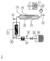
- FIG. 1 shows an example of a device according to the invention. It comprises a stirred educt template (1), which provides the reaction mixture via a delivery line with feed pump (2).
- the heating tube (7) made of microwave-transparent material
- the heating tube (7) is flowed through by the reaction mixture in the indicated direction (5).
- the heating tube is located in a microwave applicator (4).
- At the end of the heating zone there is a measuring point for temperature and optionally pressure (8).
- the reaction mixture is transferred to the isothermal reaction zone (9).
- At the outlet of the isothermal reaction section (9) there is a measuring point for temperature (10).
- Behind the isothermal reaction section is a condenser (11), followed by a pressure and temperature measuring point (12). After passing through the cooler, the product passes through an expansion valve (13) in the product template (14).
- FIG. 2 shows an example of a further device according to the invention, in which serves as a microwave oven (4), a single-mode applicator in which the propagation direction of the microwaves (6) parallel or anti-parallel to Flow direction of the reaction mixture (5).
- the isothermal reaction section (9) and the cooler (11) are designed here as tube coils.
- the irradiations of the reaction mixtures with microwaves were carried out in an apparatus which contained as a heating tube a ceramic tube (60 ⁇ 1 cm), which was axially symmetrical in a cylindrical cavity resonator (60 ⁇ 10 cm). On one of the end faces of the cavity resonator, this heating tube passed through the cavity of an inner conductor tube acting as a coupling antenna.
- the 2.45 GHz frequency microwave field generated by a magnetron was coupled into the cavity by means of the coupling antenna (E 01 cavity applicator, single mode) in which a standing wave was formed.
- the heated reaction mixtures were then immediately passed through a thermally insulated stainless steel tube (3.0 mx 1 cm, unless stated otherwise). After leaving this reaction tube, the reaction mixtures were decompressed to atmospheric pressure and immediately cooled by means of an intensive heat exchanger to about 60 ° C.
- the microwave power was adjusted over the duration of each experiment in such a way that the desired temperature of the reaction mixture was kept constant at the end of the heating zone.
- the microwave powers mentioned in the test descriptions therefore represent the time average of the irradiated microwave power.
- the temperature measurement of the reaction mixture was made directly after leaving the heating zone (about 15 cm distance in an insulated stainless steel capillary, ⁇ 1 cm) and after leaving the reaction zone by means of Pt100 temperature sensor.
- Microwave energy not directly absorbed by the reaction mixture was reflected at the end face of the cavity resonator opposite the coupling antenna; the microwave energy which was not absorbed by the reaction mixture during the return and was reflected back in the direction of the magnetron was conducted by means of a prism system (circulator) into a vessel containing water. Out the difference between radiated energy and heating of this water load was calculated in the reaction mixture registered microwave energy.
- reaction mixture was set in the apparatus under such a working pressure, which was sufficient to keep all starting materials and products or condensation products always in the liquid state.
- the reaction mixtures were pumped through the device at a constant flow rate and the residence time in the heating zone and reaction zone was adjusted by modifying the flow rate.
- the resulting mixture was pumped through the apparatus at a working pressure of 35 bar continuously at 10.0 l / h, while exposed in the heating zone of a microwave power of 4.8 kW, of which 94% were absorbed by the reaction mixture.
- the residence time of the reaction mixture in the heating zone was about 17 seconds, the residence time in the reaction zone about 85 seconds.
- the reaction mixture had a temperature of 296 ° C, after leaving the reaction zone a temperature of 292 ° C.
- the reaction mixture thus obtained was continuously pumped through the apparatus at 5.5 l / h at a working pressure of 32 bar and subjected to a microwave power of 2.7 kW in the heating zone, of which 90% was absorbed by the reaction mixture.
- the residence time of the reaction mixture in the heating zone was about 31 seconds, the residence time in the reaction zone about 155 seconds.
- the reaction mixture had a temperature of 260 ° C, after leaving the reaction zone a temperature of 258 ° C.
- reaction product was slightly yellowish in color. After distillative removal of excess diethylamine, neutralization of the catalyst with dilute acetic acid and separation of the resulting glycerol / water phase 4.66 kg N, N-Diethylcocosfettklamid were obtained with a purity of> 97%.
- the catalyst suspension was slowly added under nitrogen inertization in the stirred autoclave and stirred in a homogeneous manner.
- the readily pumpable suspension thus obtained was pumped through the apparatus at a working pressure of 30 bar continuously at 1.5 l / h and exposed in the heating zone to a microwave power of 1.2 kW, of which 92% was absorbed by the reaction mixture.
- the residence time of the reaction mixture in the heating zone was about 13 seconds, the residence time in the reaction zone about 10 minutes.
- the reaction mixture had a temperature of 255 ° C, after leaving the reaction zone a temperature of 251 ° C.
- the low-viscosity emulsion thus obtained was pumped through the apparatus at a working pressure of 30 bar continuously at 2.0 l / h and exposed in the heating zone to a microwave power of 1.8 kW, of which 90% were absorbed by the reaction mixture.
- the residence time of the reaction mixture in the heating zone was about 85 seconds.
- the reaction section was here worked with a tube with a diameter of 2 cm and a length of 10 meters, so that a residence time in the reaction zone of about 94 minutes was reached.
- the reaction mixture had a temperature of 240 ° C, after leaving the reaction zone a temperature of 235 ° C.
Landscapes
- Chemical & Material Sciences (AREA)
- Organic Chemistry (AREA)
- Physics & Mathematics (AREA)
- Electromagnetism (AREA)
- Chemical Kinetics & Catalysis (AREA)
- Health & Medical Sciences (AREA)
- General Health & Medical Sciences (AREA)
- Toxicology (AREA)
- Clinical Laboratory Science (AREA)
- General Chemical & Material Sciences (AREA)
- Medicinal Chemistry (AREA)
- Polymers & Plastics (AREA)
- Physical Or Chemical Processes And Apparatus (AREA)
- Organic Low-Molecular-Weight Compounds And Preparation Thereof (AREA)
- Constitution Of High-Frequency Heating (AREA)
Priority Applications (1)
| Application Number | Priority Date | Filing Date | Title |
|---|---|---|---|
| PL10725034T PL2448663T3 (pl) | 2009-06-30 | 2010-06-09 | Urządzenie do ciągłego przeprowadzania reakcji chemicznych w wysokich temperaturach |
Applications Claiming Priority (2)
| Application Number | Priority Date | Filing Date | Title |
|---|---|---|---|
| DE102009031059A DE102009031059A1 (de) | 2009-06-30 | 2009-06-30 | Vorrichtung zur kontinuierlichen Durchführung chemischer Reaktionen bei hohen Temperaturen |
| PCT/EP2010/003443 WO2011000460A2 (de) | 2009-06-30 | 2010-06-09 | Vorrichtung zur kontinuierlichen durchführung chemischer reaktionen bei hohen temperaturen |
Publications (2)
| Publication Number | Publication Date |
|---|---|
| EP2448663A2 EP2448663A2 (de) | 2012-05-09 |
| EP2448663B1 true EP2448663B1 (de) | 2013-04-17 |
Family
ID=43128286
Family Applications (1)
| Application Number | Title | Priority Date | Filing Date |
|---|---|---|---|
| EP10725034.2A Expired - Fee Related EP2448663B1 (de) | 2009-06-30 | 2010-06-09 | Vorrichtung zur kontinuierlichen durchführung chemischer reaktionen bei hohen temperaturen |
Country Status (15)
| Country | Link |
|---|---|
| US (1) | US8974743B2 (ko) |
| EP (1) | EP2448663B1 (ko) |
| JP (2) | JP2012531304A (ko) |
| KR (1) | KR20120090024A (ko) |
| CN (1) | CN102448603B (ko) |
| AU (2) | AU2010268445A1 (ko) |
| BR (1) | BRPI1014323A2 (ko) |
| CA (1) | CA2766950A1 (ko) |
| DE (1) | DE102009031059A1 (ko) |
| EA (1) | EA021427B1 (ko) |
| ES (1) | ES2406760T3 (ko) |
| MX (1) | MX2011011736A (ko) |
| MY (1) | MY152996A (ko) |
| PL (1) | PL2448663T3 (ko) |
| WO (1) | WO2011000460A2 (ko) |
Families Citing this family (30)
| Publication number | Priority date | Publication date | Assignee | Title |
|---|---|---|---|---|
| DE102006047617B4 (de) * | 2006-10-09 | 2008-11-27 | Clariant International Limited | Verfahren zur Herstellung basischer (Meth)acrylamide |
| DE102006047619B4 (de) * | 2006-10-09 | 2008-11-13 | Clariant International Limited | Verfahren zur Herstellung basischer Fettsäureamide |
| DE102008017219A1 (de) * | 2008-04-04 | 2009-10-08 | Clariant International Ltd. | Verfahren zur Herstellung von Amiden in Gegenwart von überhitztem Wasser |
| DE102008017215B4 (de) * | 2008-04-04 | 2012-08-09 | Clariant International Ltd. | Kontinuierliches Verfahren zur Herstellung von Amiden ethylenisch ungesättigter Carbonsäuren |
| DE102008017213B4 (de) * | 2008-04-04 | 2012-08-09 | Clariant International Limited | Kontinuierliches Verfahren zur Herstellung von Amiden aliphatischer Hydroxycarbonsäuren |
| DE102008017218B4 (de) * | 2008-04-04 | 2011-09-22 | Clariant International Ltd. | Kontinuierliches Verfahren zur Herstellung von Amiden niederer aliphatischer Carbonsäuren |
| DE102008017216B4 (de) * | 2008-04-04 | 2013-08-14 | Clariant International Ltd. | Kontinuierliches Verfahren zur Herstellung von Fettsäureamiden |
| DE102008017217A1 (de) * | 2008-04-04 | 2009-10-08 | Clariant International Ltd. | Kontinuierliches Verfahren zur Herstellung von Amiden aromatischer Carbonsäuren |
| DE102008017214B4 (de) * | 2008-04-04 | 2012-02-16 | Clariant International Limited | Kontinuierliches Verfahren zur Herstellung von Fettsäurealkanolamiden |
| DE102009031058A1 (de) * | 2009-06-30 | 2011-01-27 | Clariant International Ltd. | Kontinuierliches Verfahren zur Herstellung von Amiden aromatischer Carbonsäuren |
| DE102009042523B4 (de) | 2009-09-22 | 2012-02-16 | Clariant International Ltd. | Vorrichtung und Verfahren zur kontinuierlichen Durchführung heterogen katalysierter chemischer Reaktionen bei hohen Temperaturen |
| DE102009042522A1 (de) | 2009-09-22 | 2011-04-07 | Clariant International Ltd. | Kontinuierliches Umesterungsverfahren |
| DE102010056564A1 (de) | 2010-12-30 | 2012-07-05 | Clariant International Limited | Hydroxylgruppen und Estergruppen tragende Polymere und Verfahren zu ihrer Herstellung |
| DE102010056565A1 (de) | 2010-12-30 | 2012-07-05 | Clariant International Ltd. | Verfahren zur Modifizierung Hydroxylgruppen tragender Polymere |
| DE102011102975A1 (de) * | 2011-05-31 | 2012-12-06 | Linde Aktiengesellschaft | Reaktoreinrichtung |
| EP2911976B1 (en) * | 2012-10-24 | 2019-06-19 | H2 Energy Now | Generating energy from water, to hydrogen system |
| JP6182767B2 (ja) * | 2013-03-19 | 2017-08-23 | 株式会社サイダ・Fds | 流通管を備えたマイクロ波装置 |
| DE102013016660A1 (de) * | 2013-10-09 | 2015-04-09 | Ralf Spitzl | Verfahren und Vorrichtung zur plasmakatalytischen Umsetzung von Stoffen |
| CN107051350B (zh) * | 2017-05-18 | 2023-06-20 | 华南理工大学 | 一种基于微波的双源热耦合化学链气化方法及其装置 |
| CN108828472B (zh) * | 2018-03-30 | 2020-10-16 | 上海通用卫星导航有限公司 | 一种用于铯光泵磁力仪的加热装置 |
| US11633710B2 (en) | 2018-08-23 | 2023-04-25 | Transform Materials Llc | Systems and methods for processing gases |
| WO2020041597A1 (en) | 2018-08-23 | 2020-02-27 | Transform Materials Llc | Systems and methods for processing gases |
| JP7316505B2 (ja) * | 2018-09-28 | 2023-07-28 | 国立大学法人東京農工大学 | 発熱体、発熱体の製造方法、および加熱装置 |
| JP2020053336A (ja) * | 2018-09-28 | 2020-04-02 | 国立大学法人東京農工大学 | 発熱体、発熱体の製造方法、および加熱装置 |
| GB201908940D0 (en) | 2019-06-21 | 2019-08-07 | C Tech Innovation Ltd | Electromagnetic heating reactor |
| DE102019006639A1 (de) * | 2019-09-20 | 2021-03-25 | Fraunhofer-Gesellschaft zur Förderung der angewandten Forschung e.V. | Kontinuierliches Verfahren zum Erhitzen von Medien mittels Mikrowellenstrahlung und dafür geeignete Mikrowellenanlage |
| CN112973597A (zh) * | 2019-12-17 | 2021-06-18 | 江苏麦克威微波技术有限公司 | 处理液体的微波装置及系统 |
| KR102327152B1 (ko) | 2020-04-03 | 2021-11-17 | 한국과학기술연구원 | 압력 예비 설정 기능을 갖는 마이크로웨이브를 이용한 대용량 천연소재 성분변환 장치 |
| US11945764B2 (en) | 2021-06-09 | 2024-04-02 | Ut-Battelle, Llc | Efficient synthesis of diglycolamide molecules |
| NL2030194B1 (en) * | 2021-12-20 | 2023-06-28 | Fassin Tussenhoudster B V | a method of processing a flow of confectionary mass and a device arranged for heating a flow of confectionary mass |
Family Cites Families (146)
| Publication number | Priority date | Publication date | Assignee | Title |
|---|---|---|---|---|
| DE480866C (de) | 1924-07-20 | 1929-08-15 | Consortium Elektrochem Ind | Verfahren zur Darstellung von Derivaten des polymeren Vinylalkohols |
| US1972142A (en) | 1931-04-07 | 1934-09-04 | Ici Ltd | Process for the production of carboxylic acid amides |
| US2601561A (en) | 1949-05-05 | 1952-06-24 | Hercules Powder Co Ltd | Synthetic drying oils from polyvinyl alcohol and method of production |
| US3113026A (en) | 1959-01-19 | 1963-12-03 | Gen Aniline & Film Corp | Polyvinyl alcohol photographic silver halide emulsions |
| US3024260A (en) | 1959-10-15 | 1962-03-06 | Textilana Corp | Process for the production of fatty hydroxyalkylamides |
| US3050418A (en) | 1959-11-09 | 1962-08-21 | Yardney International Corp | Process for imparting wettability to shaped hydrophobic polymeric material |
| NL289475A (ko) | 1962-03-01 | |||
| US3395162A (en) | 1963-08-26 | 1968-07-30 | Lever Brothers Ltd | Process for the preparation of amides |
| US3585224A (en) | 1966-09-09 | 1971-06-15 | Basf Ag | Production of amides and polyamides |
| CH519006A (de) | 1969-03-06 | 1972-02-15 | Ciba Geigy Ag | Verwendung von neuen Azol-Derivaten als optische Aufhellmittel für organische Materialien ausserhalb der Textilindustrie |
| NL7100453A (ko) | 1970-01-30 | 1971-08-03 | ||
| US3652671A (en) | 1970-06-01 | 1972-03-28 | Dow Chemical Co | Process for making a cationic methacrylamide |
| US3652434A (en) | 1970-10-02 | 1972-03-28 | Cornell Research Foundations I | Pressure wave synthesis of aminocarboxylic acids |
| DE2620638C3 (de) | 1976-05-10 | 1979-03-29 | Ingenieurbuero Hermann Purfuerst Kg, 3004 Isernhagen | Vorrichtung zum kontinuierlichen dielektrischen Erwärmen mittels Mikrowellenenergie |
| FR2371226A1 (fr) | 1976-11-17 | 1978-06-16 | Olivier Jean | Applicateur pour soumettre une matiere a des ondes |
| DE2857828C2 (ko) | 1977-01-27 | 1990-06-07 | Toyo Soda Mfg. Co., Ltd., Shinnanyo, Yamaguchi, Jp | |
| US4133833A (en) | 1978-01-09 | 1979-01-09 | Pfizer Inc. | Production of N,N-di(ethyl)-meta-toluamide from meta-toluic acid by liquid phase catalytic reaction with diethylamine |
| IT1137506B (it) | 1981-03-13 | 1986-09-10 | Anic Spa | Composizione per il rivestimento delle pareti dei reattori e delle apparecchiature collegate,destinate alla polimerizzazione di composti vinilici,idonea ad evitare o ridurre depositi ed incrostazioni delle stesse apparecchiature e metodo per la sua utilizzazione |
| JPS57155231A (en) | 1981-03-23 | 1982-09-25 | Daicel Chem Ind Ltd | Polyol resin |
| DE3209800C2 (de) | 1982-03-18 | 1990-03-08 | Chemische Fabrik Stockhausen GmbH, 4150 Krefeld | Verfahren zur Herstellung von N-(tert. Aminoalkyl)acrylamiden |
| DE3325738A1 (de) | 1983-07-16 | 1985-01-24 | Basf Ag, 6700 Ludwigshafen | Wasserloesliche ester von polymerisaten der acrylsaeure |
| DD224203A1 (de) | 1984-04-16 | 1985-07-03 | Fahlberg List Veb | Polymere phytoeffektoren als neue mittel zur biologischen prozesssteuerung |
| IT1190375B (it) | 1985-06-20 | 1988-02-16 | Recordati Chem Pharm | N-benzidrildiazacicloalchil-alcanilidi ad attivita' antianafilattica ed antibroncospastica |
| FR2590567B1 (fr) | 1985-11-27 | 1988-07-15 | Charbonnages Ste Chimique | Nouveau procede de synthese de (meth)acrylamide de n-dialkylaminoalkyle |
| JPH01133910A (ja) * | 1987-06-08 | 1989-05-26 | Cil Inc | マイクロ波エネルギ−を使用して発煙硫酸から三酸化硫黄を発生させる方法及び装置 |
| ATE112978T1 (de) | 1988-10-10 | 1994-11-15 | Commw Scient Ind Res Org | Verfahren und vorrichtung für kontinuierliche chemische reaktionen. |
| DE3900053A1 (de) | 1989-01-03 | 1990-07-12 | Bayer Ag | Verfahren zur herstellung von uretdion- und isocyanuratgruppen aufweisenden polyisocyanaten, die nach diesem verfahren erhaeltlichen polyisocyanate und ihre verwendung in zweikomponenten-polyurethanlacken |
| US5185466A (en) | 1989-01-05 | 1993-02-09 | Branko Kozulic | Hydrophilic and amphiphatic monomers, their polymers and gels and hydrophobic electrophoresis |
| US4915974A (en) | 1989-02-17 | 1990-04-10 | Nabisco Brands, Inc. | Polyvinyl oleate as a fat replacement |
| US5114684A (en) | 1990-12-13 | 1992-05-19 | Serawaste Systems Corporation | In-line electromagnetic energy wave applicator |
| CH681586A5 (en) | 1991-01-25 | 1993-04-15 | Inwave Ag | Microwave heater for fluids - has fluid flow path incorporated in part of microwave line for direct microwave heating |
| AU649770B2 (en) | 1991-01-25 | 1994-06-02 | Societe Prolabo | Apparatus for simultaneous treatment, in a moist medium, on a plurality of samples, and utilisation of the said apparatus |
| US5326538A (en) | 1991-03-13 | 1994-07-05 | Serawaste Systems Corporation | Closed sterilization system for treating a product such as toxic or infectious waste |
| EP0583685B1 (de) | 1992-08-15 | 1996-05-29 | Hoechst Aktiengesellschaft | Verfahren zur Reinigung von Fettsäureamiden |
| US5331045A (en) | 1993-02-12 | 1994-07-19 | E. I. Du Pont De Nemours And Company | Polyvinyl alcohol esterified with lactic acid and process therefor |
| GB9318288D0 (en) | 1993-09-03 | 1993-10-20 | Nycomed Imaging As | Improvements in or relating to contrast agents |
| DE69422062T2 (de) | 1993-09-29 | 2000-05-25 | Grace W R & Co | Zusammensetzung zum verbessern der rheologischen eigenschaften zementbasierter produkte und verfahren zur herstellung davon |
| AU677876B2 (en) * | 1993-10-28 | 1997-05-08 | Commonwealth Scientific And Industrial Research Organisation | Batch microwave reactor |
| US5892115A (en) | 1996-01-16 | 1999-04-06 | Showa Denko Kabushiki Kaisha | Highly polymerizable N-vinylcarboxylic acid amide and production process thereof |
| DE4429550A1 (de) | 1994-08-19 | 1996-02-22 | Henkel Kgaa | Verfahren zur Herstellung von Wasch- oder Reinigungsmitteltabletten |
| DE4433977A1 (de) | 1994-09-23 | 1996-03-28 | Basf Ag | Verfahren zur Herstellung von N-Acylaminocarbonsäuren und N-Acylaminosulfonsäuren sowie deren Alkalimetallsalzen |
| GB9422093D0 (en) | 1994-11-02 | 1994-12-21 | Zeneca Ltd | Rheology modifier for solvent-based coatings |
| US5589522A (en) | 1994-12-21 | 1996-12-31 | Lexmark International, Inc. | Ink composition |
| JP3335492B2 (ja) * | 1994-12-28 | 2002-10-15 | 三菱電機株式会社 | 薄膜の堆積装置 |
| US5646318A (en) | 1995-04-26 | 1997-07-08 | Akzo Nobel Nv | Process for the preparation of hydroxyalkylamides |
| US5710295A (en) | 1995-06-06 | 1998-01-20 | Hampshire Chemical Corp. | Preparation of alkali metal acyl amino acids |
| US5646319A (en) | 1995-06-23 | 1997-07-08 | The Procter & Gamble Company | Synthesis of N-acyl-N-alkylcarboxylates |
| JPH09316127A (ja) | 1996-03-26 | 1997-12-09 | Fuji Photo Film Co Ltd | エステル置換ポリビニルアルコールの製造方法およびそれを用いた薄膜 |
| FR2751830B1 (fr) | 1996-07-23 | 1998-10-23 | Prolabo Sa | Dispositif pour realiser des reactions chimiques sous micro-ondes sur une grande quantite de produits |
| GB9622159D0 (en) | 1996-10-24 | 1996-12-18 | Solvay Sociutu Anonyme | Polyanionic polymers as adjuvants for mucosal immunization |
| TW353674B (en) | 1996-12-31 | 1999-03-01 | Shell Int Research | Prereacted surfactant composition and water borne curing agent composition for self-curing epoxy resins at ambient or sub-ambient temperatures, comprising said surfactant composition |
| US5969052A (en) | 1996-12-31 | 1999-10-19 | Kimberly Clark Worldwide, Inc. | Temperature sensitive polymers and water-dispersible products containing the polymers |
| US5804653A (en) | 1997-03-07 | 1998-09-08 | Playtex Products, Inc. | Polyvinyl alcohol compound |
| US6107498A (en) | 1997-04-22 | 2000-08-22 | Akzo Nobel N.V. | Process for making carboxylic amides |
| US6291712B1 (en) | 1997-05-19 | 2001-09-18 | Showa Denko K.K. | Process for producing saturated aliphatic carboxylic acid amide |
| JPH10330338A (ja) | 1997-05-28 | 1998-12-15 | Kao Corp | N−アルキルアミドアルカノールの製造方法 |
| FR2764603B1 (fr) | 1997-06-11 | 1999-07-30 | Oreal | Procede de preparation de composes de type ceramides |
| JPH11135252A (ja) * | 1997-08-12 | 1999-05-21 | Matsushita Electric Ind Co Ltd | マイクロ波を用いた加熱装置およびその装置による接合対象の接合方法 |
| US5988877A (en) | 1997-09-15 | 1999-11-23 | C E M Corporation | Method and apparatus for temperature calibration in microwave assisted chemistry |
| JP2002511386A (ja) | 1997-12-22 | 2002-04-16 | イーライ・リリー・アンド・カンパニー | アミド形成反応のための触媒およびその方法 |
| US6175037B1 (en) | 1998-10-09 | 2001-01-16 | Ucb, S.A. | Process for the preparation of (meth)acrylate esters and polyester (meth)acrylates using microwave energy as a heating source |
| US6127560A (en) | 1998-12-29 | 2000-10-03 | West Central Cooperative | Method for preparing a lower alkyl ester product from vegetable oil |
| US6281484B2 (en) | 1999-01-21 | 2001-08-28 | Cem Corporation | In-cavity connectors for system detectors in microwave assisted processes |
| AU8027800A (en) * | 1999-10-18 | 2001-04-30 | Penn State Research Foundation, The | Microwave processing in pure h fields and pure e fields |
| JP2001210349A (ja) * | 2000-01-24 | 2001-08-03 | Sanyo Electric Co Ltd | 燃料電池発電システム及びその起動方法 |
| CN1248778C (zh) | 2000-02-25 | 2006-04-05 | 私人化学乌普萨拉股份公司 | 微波加热装置 |
| GB2361918A (en) | 2000-05-06 | 2001-11-07 | Interpole Ltd | Transesterification and Hyrolysis Reactions activated by Microwave Radiation |
| CN1142086C (zh) | 2000-11-15 | 2004-03-17 | 中国科学院金属研究所 | 一种用于甲烷与二氧化碳重整反应的微波催化剂及其制备方法 |
| DE10122011A1 (de) | 2001-05-07 | 2002-11-14 | Hochschule Zittau Goerlitz | Verfahren zur Herstellung von Estern aus natürlich vorkommenden Fetten und Ölen |
| ITBO20010429A1 (it) | 2001-07-09 | 2003-01-09 | Ipctisa S R L | Metodi e dispositivi per idrolizzare gli esteri di acidi grassi naturali e successivamente esterificarli con metanolo in oli naturali sotto |
| DE10140597A1 (de) | 2001-08-18 | 2003-03-06 | Kuraray Specialities Europe | Teilvernetzter Polyvinylalkohol |
| DE10143377B4 (de) | 2001-09-05 | 2005-10-27 | Deutsches Zentrum für Luft- und Raumfahrt e.V. | Mikrowellenreaktor und Verfahren zur Steuerung von Reaktionen von aktivierten Molekülen |
| US20030091487A1 (en) * | 2001-10-19 | 2003-05-15 | Magnus Fagrell | Continuous flow heating system |
| WO2003041856A1 (en) * | 2001-10-19 | 2003-05-22 | Personal Chemistry I Uppsala Ab | Continuous flow system with microwave heating |
| FR2839069B1 (fr) | 2002-04-25 | 2006-04-07 | Satie Sa | Nouveaux procedes de transesterification, esterification, interesterification, par chauffage dielectrique |
| JP4276406B2 (ja) | 2002-04-30 | 2009-06-10 | トヨタ自動車株式会社 | アミド化合物およびアミノ化合物の製造方法 |
| US6867400B2 (en) | 2002-07-31 | 2005-03-15 | Cem Corporation | Method and apparatus for continuous flow microwave-assisted chemistry techniques |
| US6794510B2 (en) | 2002-08-08 | 2004-09-21 | Adolor Corporation | Processes for the preparation of peripheral opioid antagonist compounds and intermediates thereto |
| US7595138B2 (en) | 2002-12-10 | 2009-09-29 | Panasonic Corporation | Toner, two-component developer, and image forming method |
| CA2510334A1 (en) | 2002-12-18 | 2004-07-01 | Biotage Ab | Method and apparatus for control of chemical reactions |
| FR2849343B1 (fr) | 2002-12-23 | 2009-01-23 | Aldivia | Synthese chimique comportant un traitement thermique par chauffage dielectrique intermittent, combine a un systeme de recirculation |
| EP1435364A3 (en) | 2003-01-03 | 2005-11-23 | Air Products And Chemicals, Inc. | Tertiary amino alkyl amide polyurethane catalysts derived from long chain alkyl or fatty carboxylic acids |
| PL378117A1 (pl) | 2003-02-11 | 2006-03-06 | Prosidion Limited | Tricyklopodstawione związki amidowe |
| US20050027120A1 (en) | 2003-06-02 | 2005-02-03 | Reactimex, S.A. De C.V. | Method for the synthesis of amides and related products from esters or ester-like compounds |
| US7393920B2 (en) | 2003-06-23 | 2008-07-01 | Cem Corporation | Microwave-assisted peptide synthesis |
| JP4372482B2 (ja) | 2003-08-08 | 2009-11-25 | トヨタ自動車株式会社 | アミド化合物の製造方法 |
| US6989519B2 (en) | 2003-09-02 | 2006-01-24 | Cem Corporation | Controlled flow instrument for microwave assisted chemistry with high viscosity liquids and heterogeneous mixtures |
| WO2005033062A1 (ja) | 2003-10-06 | 2005-04-14 | Lion Akzo Co., Ltd. | カルボン酸アミド及びその誘導体の製造方法 |
| JP4022635B2 (ja) * | 2003-12-12 | 2007-12-19 | 大学共同利用機関法人自然科学研究機構 | 化学反応炉 |
| US7473739B2 (en) | 2004-02-05 | 2009-01-06 | Nippon Shokubai Co., Ltd. | Particulate water absorbent agent and production method thereof, and water absorbent article |
| US7601329B2 (en) * | 2004-02-26 | 2009-10-13 | Gm Global Technology Operations, Inc. | Regeneration of hydrogen storage system materials and methods including hydrides and hydroxides |
| WO2005102510A1 (ja) * | 2004-04-20 | 2005-11-03 | Sanko Chemical Industry Co., Ltd. | マイクロ波を応用した化学反応装置 |
| JP4759668B2 (ja) | 2004-05-11 | 2011-08-31 | 株式会社Idx | マイクロ波加熱装置 |
| US7425527B2 (en) | 2004-06-04 | 2008-09-16 | The Procter & Gamble Company | Organic activator |
| US20050274065A1 (en) | 2004-06-15 | 2005-12-15 | Carnegie Mellon University | Methods for producing biodiesel |
| MY143828A (en) | 2004-06-17 | 2011-07-15 | Malaysian Palm Oil Board | A process for the production of fatty acid amides |
| GB0414366D0 (en) | 2004-06-26 | 2004-07-28 | Irving Alan M | Clothing/equipment safety light |
| US7150836B2 (en) | 2004-07-16 | 2006-12-19 | Battelle Energy Alliance, Llc | Microwave-emitting rotor, separator apparatus including same, methods of operation and design thereof |
| CN100575368C (zh) | 2004-08-04 | 2009-12-30 | 积水化学工业株式会社 | 聚乙烯醇缩醛树脂的制造方法、聚乙烯醇缩丁醛树脂、以及被酯化的聚乙烯醇树脂的制造方法 |
| EP1827678B1 (en) | 2004-08-31 | 2012-07-18 | Total Synthesis Ltd. | Method and apparatus for performing micro-scale chemical reactions |
| DE102005048201A1 (de) * | 2004-10-11 | 2006-04-20 | Penth, Bernd, Dr. | Kontinuierliche Fällung von nanoskaligen Produkten in Mikroreaktoren |
| JP2006272055A (ja) | 2005-03-28 | 2006-10-12 | Idx Corp | マイクロ波化学反応装置 |
| JP2006181533A (ja) | 2004-12-28 | 2006-07-13 | Idx Corp | マイクロ波化学反応装置 |
| US20060291827A1 (en) | 2005-02-11 | 2006-12-28 | Suib Steven L | Process and apparatus to synthesize materials |
| DE102005017453A1 (de) | 2005-04-15 | 2006-10-19 | Clariant Produkte (Deutschland) Gmbh | Verfahren zur Herstellung von Amiden basierend auf Polyetheraminen und (Meth)acrylsäure |
| GB0512183D0 (en) | 2005-06-15 | 2005-07-20 | Tooley John K | Improvements relating to the refining of waste oil |
| DE102005040617A1 (de) | 2005-08-27 | 2007-03-22 | Bayer Materialscience Ag | Verfahren zur Herstellung von Polyesterpolyolen und deren Verwendung |
| CN100334115C (zh) | 2005-10-12 | 2007-08-29 | 江南大学 | 微波法酸解与酯化改性复合变性淀粉的制备方法和应用 |
| DE102005051637A1 (de) * | 2005-10-26 | 2007-05-03 | Atotech Deutschland Gmbh | Reaktorsystem mit einem mikrostrukturierten Reaktor sowie Verfahren zur Durchführung einer chemischen Reaktion in einem solchen Reaktor |
| WO2007065681A1 (en) | 2005-12-08 | 2007-06-14 | Ciba Holding Inc. | A process for the preparation of hydroxy polymer esters and their use |
| BRPI0709247A2 (pt) | 2006-03-28 | 2011-07-12 | Basf Se | tubo, recipiente de armazenagem, e, usos de um tubo, e do recipiente de armazenagem |
| EP1849854A1 (en) | 2006-04-26 | 2007-10-31 | Dall 'Oglio, Evandro Luiz | Biodiesel production process through transesterification/esterification reaction of vegetal oils or animal fats with alcohols induced by microwave radiation |
| CN101198677B (zh) | 2006-04-28 | 2012-11-14 | Sk化学股份有限公司 | 使用脂肪酸制备脂肪酸烷基酯的方法和设备 |
| MX2009000117A (es) | 2006-07-06 | 2009-01-23 | Glaxo Group Ltd | N-fenilmetil-5-oxo-prolin-2-amidas sustituidas como antagonistas de receptores p2x7 y sus metodos de uso. |
| EP1884559A1 (en) | 2006-07-26 | 2008-02-06 | Vlaamse Instelling Voor Technologisch Onderzoek (Vito) | Novel method for producing biodiesel using an immobilised catalyst |
| JP5013509B2 (ja) | 2006-07-28 | 2012-08-29 | 国立大学法人東北大学 | ジアミド化合物の製造方法及びジアミン化合物の製造方法 |
| CN1931980A (zh) | 2006-09-29 | 2007-03-21 | 陈必昌 | 一种制备五金加工润滑剂的方法 |
| DE102006047619B4 (de) | 2006-10-09 | 2008-11-13 | Clariant International Limited | Verfahren zur Herstellung basischer Fettsäureamide |
| DE102006047620B4 (de) * | 2006-10-09 | 2008-11-27 | Clariant International Limited | Verfahren zur Herstellung tertiärer Amide von Alkylphenylcarbonsäuren |
| DE102006047617B4 (de) | 2006-10-09 | 2008-11-27 | Clariant International Limited | Verfahren zur Herstellung basischer (Meth)acrylamide |
| DE102006047618B3 (de) | 2006-10-09 | 2007-11-15 | Clariant International Limited | Verfahren zur Herstellung von Bisbenzoxazolen |
| AU2007306664A1 (en) | 2006-10-09 | 2008-04-17 | Clariant Finance (Bvi) Limited | Method for producing fatty acid alkanol amides |
| GB0625321D0 (en) | 2006-12-19 | 2007-01-24 | Univ Surrey | Cancer biomarker |
| BRPI0701638B1 (pt) | 2007-04-24 | 2016-10-11 | Petróleo Brasileiro S A Petrobras | reator e sistema para hidroprocessamento assistido por microondas |
| US20090005582A1 (en) | 2007-06-22 | 2009-01-01 | Greg Anderson | Vessels and methods for synthesis of biofuel |
| WO2009064501A1 (en) | 2007-11-14 | 2009-05-22 | Saudi Arabian Oil Company | Microwave-promoted desulfurization of crude oil |
| DE102008017218B4 (de) | 2008-04-04 | 2011-09-22 | Clariant International Ltd. | Kontinuierliches Verfahren zur Herstellung von Amiden niederer aliphatischer Carbonsäuren |
| DE102008017215B4 (de) | 2008-04-04 | 2012-08-09 | Clariant International Ltd. | Kontinuierliches Verfahren zur Herstellung von Amiden ethylenisch ungesättigter Carbonsäuren |
| DE102008017213B4 (de) | 2008-04-04 | 2012-08-09 | Clariant International Limited | Kontinuierliches Verfahren zur Herstellung von Amiden aliphatischer Hydroxycarbonsäuren |
| DE102008017219A1 (de) | 2008-04-04 | 2009-10-08 | Clariant International Ltd. | Verfahren zur Herstellung von Amiden in Gegenwart von überhitztem Wasser |
| DE102008017216B4 (de) | 2008-04-04 | 2013-08-14 | Clariant International Ltd. | Kontinuierliches Verfahren zur Herstellung von Fettsäureamiden |
| DE102008017217A1 (de) | 2008-04-04 | 2009-10-08 | Clariant International Ltd. | Kontinuierliches Verfahren zur Herstellung von Amiden aromatischer Carbonsäuren |
| DE102008017214B4 (de) | 2008-04-04 | 2012-02-16 | Clariant International Limited | Kontinuierliches Verfahren zur Herstellung von Fettsäurealkanolamiden |
| JP5127549B2 (ja) | 2008-04-24 | 2013-01-23 | パナソニック株式会社 | 高分子化合物の改質方法、プラスチック用低収縮材及び高分子化合物の利用方法 |
| DE102009001382A1 (de) | 2009-03-06 | 2010-09-09 | Kuraray Europe Gmbh | Hydrophob modifizierte Polyvinylalkohole und Polyvinylacetale |
| DE102009031053A1 (de) | 2009-06-30 | 2011-01-13 | Clariant International Ltd. | Kontinuierliches Verfahren zur Herstellung von Estern aliphatischer Carbonsäuren |
| DE102009031058A1 (de) | 2009-06-30 | 2011-01-27 | Clariant International Ltd. | Kontinuierliches Verfahren zur Herstellung von Amiden aromatischer Carbonsäuren |
| DE102009031056A1 (de) | 2009-06-30 | 2011-01-27 | Clariant International Ltd. | Kontinuierliches Verfahren zur Acrylierung von Aminogruppen tragenden organischen Säuren |
| DE102009031057A1 (de) | 2009-06-30 | 2011-01-05 | Clariant International Ltd. | Kontinuierliches Verfahren zur Herstellung von Amiden aliphatischer Carbonsäuren |
| DE102009031054A1 (de) | 2009-06-30 | 2011-01-13 | Clariant International Ltd. | Kontinuierliches Verfahren zur Herstellung von Estern aromatischer Carbonsäuren |
| DE102009042522A1 (de) * | 2009-09-22 | 2011-04-07 | Clariant International Ltd. | Kontinuierliches Umesterungsverfahren |
| DE102009042523B4 (de) | 2009-09-22 | 2012-02-16 | Clariant International Ltd. | Vorrichtung und Verfahren zur kontinuierlichen Durchführung heterogen katalysierter chemischer Reaktionen bei hohen Temperaturen |
| DE102010056565A1 (de) | 2010-12-30 | 2012-07-05 | Clariant International Ltd. | Verfahren zur Modifizierung Hydroxylgruppen tragender Polymere |
| DE102010056566A1 (de) | 2010-12-30 | 2012-07-05 | Clariant International Ltd. | Kontinuierliches Verfahren zur Veresterung Säuregruppen tragender Polymere |
| DE102010056578A1 (de) | 2010-12-30 | 2012-07-05 | Clariant International Ltd. | Hydroxylgruppen und Estergruppen tragende Polymere und Verfahren zu ihrer Herstellung |
| DE102010056579A1 (de) | 2010-12-30 | 2012-07-05 | Clariant International Limited | Kontinuierliches Verfahren zur Umsetzung Säuregruppen tragender Polymere mit Aminen |
-
2009
- 2009-06-30 DE DE102009031059A patent/DE102009031059A1/de not_active Withdrawn
-
2010
- 2010-06-09 BR BRPI1014323A patent/BRPI1014323A2/pt active Search and Examination
- 2010-06-09 EP EP10725034.2A patent/EP2448663B1/de not_active Expired - Fee Related
- 2010-06-09 JP JP2012518031A patent/JP2012531304A/ja active Pending
- 2010-06-09 PL PL10725034T patent/PL2448663T3/pl unknown
- 2010-06-09 MX MX2011011736A patent/MX2011011736A/es active IP Right Grant
- 2010-06-09 MY MYPI2011004157 patent/MY152996A/en unknown
- 2010-06-09 EA EA201200070A patent/EA021427B1/ru not_active IP Right Cessation
- 2010-06-09 ES ES10725034T patent/ES2406760T3/es active Active
- 2010-06-09 WO PCT/EP2010/003443 patent/WO2011000460A2/de active Application Filing
- 2010-06-09 CN CN201080017588.1A patent/CN102448603B/zh not_active Expired - Fee Related
- 2010-06-09 KR KR1020127002633A patent/KR20120090024A/ko not_active Application Discontinuation
- 2010-06-09 AU AU2010268445A patent/AU2010268445A1/en not_active Abandoned
- 2010-06-09 US US13/378,258 patent/US8974743B2/en not_active Expired - Fee Related
- 2010-06-09 CA CA2766950A patent/CA2766950A1/en not_active Abandoned
-
2015
- 2015-07-16 JP JP2015142002A patent/JP5996736B2/ja not_active Expired - Fee Related
-
2016
- 2016-07-08 AU AU2016204757A patent/AU2016204757A1/en not_active Abandoned
Also Published As
| Publication number | Publication date |
|---|---|
| US8974743B2 (en) | 2015-03-10 |
| BRPI1014323A2 (pt) | 2016-04-05 |
| EP2448663A2 (de) | 2012-05-09 |
| KR20120090024A (ko) | 2012-08-16 |
| PL2448663T3 (pl) | 2013-09-30 |
| US20120088885A1 (en) | 2012-04-12 |
| WO2011000460A2 (de) | 2011-01-06 |
| CN102448603B (zh) | 2015-05-13 |
| CN102448603A (zh) | 2012-05-09 |
| JP2016021399A (ja) | 2016-02-04 |
| DE102009031059A1 (de) | 2011-01-05 |
| JP2012531304A (ja) | 2012-12-10 |
| AU2016204757A1 (en) | 2016-07-28 |
| ES2406760T3 (es) | 2013-06-10 |
| JP5996736B2 (ja) | 2016-09-21 |
| AU2010268445A1 (en) | 2011-11-03 |
| EA201200070A1 (ru) | 2012-05-30 |
| MY152996A (en) | 2014-12-31 |
| MX2011011736A (es) | 2011-11-29 |
| EA021427B1 (ru) | 2015-06-30 |
| WO2011000460A3 (de) | 2011-03-31 |
| CA2766950A1 (en) | 2011-01-06 |
Similar Documents
| Publication | Publication Date | Title |
|---|---|---|
| EP2448663B1 (de) | Vorrichtung zur kontinuierlichen durchführung chemischer reaktionen bei hohen temperaturen | |
| EP2448905B1 (de) | Kontinuierliches verfahren zur herstellung von estern aliphatischer carbonsäuren | |
| EP2448913B1 (de) | Kontinuierliches verfahren zur acylierung von aminogruppen tragenden organischen säuren | |
| EP2480644B1 (de) | Kontinuierliches umesterungsverfahren | |
| DE102008017218B4 (de) | Kontinuierliches Verfahren zur Herstellung von Amiden niederer aliphatischer Carbonsäuren | |
| EP2448904B1 (de) | Kontinuierliches verfahren zur herstellung von estern aromatischer carbonsäuren | |
| EP2448915B1 (de) | Kontinuierliches verfahren zur herstellung von amiden aliphatischer carbonsäuren | |
| EP2448914B1 (de) | Kontinuierliches verfahren zur herstellung von amiden aromatischer carbonsäuren | |
| DE102008017213B4 (de) | Kontinuierliches Verfahren zur Herstellung von Amiden aliphatischer Hydroxycarbonsäuren | |
| WO2009121487A1 (de) | Kontinuierliches verfahren zur herstellung von fettsäureamiden | |
| EP2480327B1 (de) | Vorrichtung und verfahren zur kontinuierlichen durchführung heterogen katalysierter chemischer reaktionen bei hohen temperaturen | |
| WO2009121484A1 (de) | Kontinuierliches verfahren zur herstellung von amiden aromatischer carbonsäuren | |
| WO2021052618A1 (de) | Kontinuierliches verfahren zum erhitzen von medien mittels mikrowellenstrahlung und dafür geeignete mikrowellenanlage |
Legal Events
| Date | Code | Title | Description |
|---|---|---|---|
| PUAI | Public reference made under article 153(3) epc to a published international application that has entered the european phase |
Free format text: ORIGINAL CODE: 0009012 |
|
| 17P | Request for examination filed |
Effective date: 20120130 |
|
| AK | Designated contracting states |
Kind code of ref document: A2 Designated state(s): AL AT BE BG CH CY CZ DE DK EE ES FI FR GB GR HR HU IE IS IT LI LT LU LV MC MK MT NL NO PL PT RO SE SI SK SM TR |
|
| DAX | Request for extension of the european patent (deleted) | ||
| GRAP | Despatch of communication of intention to grant a patent |
Free format text: ORIGINAL CODE: EPIDOSNIGR1 |
|
| RIC1 | Information provided on ipc code assigned before grant |
Ipc: C07C 233/36 20060101ALI20121121BHEP Ipc: C07C 231/02 20060101ALI20121121BHEP Ipc: C07C 15/14 20060101ALI20121121BHEP Ipc: C07C 69/52 20060101ALI20121121BHEP Ipc: C07C 67/08 20060101ALI20121121BHEP Ipc: C07C 1/32 20060101ALI20121121BHEP Ipc: H05B 6/80 20060101ALI20121121BHEP Ipc: C07C 51/567 20060101ALI20121121BHEP Ipc: C07C 69/24 20060101ALI20121121BHEP Ipc: C07D 307/60 20060101ALI20121121BHEP Ipc: B01J 19/12 20060101AFI20121121BHEP Ipc: C07C 233/05 20060101ALI20121121BHEP Ipc: C07C 233/09 20060101ALI20121121BHEP Ipc: C07C 55/02 20060101ALI20121121BHEP |
|
| RBV | Designated contracting states (corrected) |
Designated state(s): AT BE DE ES FI FR GB IT NL PL SE TR |
|
| GRAS | Grant fee paid |
Free format text: ORIGINAL CODE: EPIDOSNIGR3 |
|
| GRAA | (expected) grant |
Free format text: ORIGINAL CODE: 0009210 |
|
| AK | Designated contracting states |
Kind code of ref document: B1 Designated state(s): AT BE DE ES FI FR GB IT NL PL SE TR |
|
| REG | Reference to a national code |
Ref country code: GB Ref legal event code: FG4D Free format text: NOT ENGLISH |
|
| REG | Reference to a national code |
Ref country code: SE Ref legal event code: TRGR |
|
| REG | Reference to a national code |
Ref country code: AT Ref legal event code: REF Ref document number: 606897 Country of ref document: AT Kind code of ref document: T Effective date: 20130515 |
|
| REG | Reference to a national code |
Ref country code: ES Ref legal event code: FG2A Ref document number: 2406760 Country of ref document: ES Kind code of ref document: T3 Effective date: 20130610 |
|
| REG | Reference to a national code |
Ref country code: DE Ref legal event code: R096 Ref document number: 502010003019 Country of ref document: DE Effective date: 20130613 |
|
| REG | Reference to a national code |
Ref country code: NL Ref legal event code: T3 |
|
| REG | Reference to a national code |
Ref country code: PL Ref legal event code: T3 |
|
| PLBE | No opposition filed within time limit |
Free format text: ORIGINAL CODE: 0009261 |
|
| STAA | Information on the status of an ep patent application or granted ep patent |
Free format text: STATUS: NO OPPOSITION FILED WITHIN TIME LIMIT |
|
| 26N | No opposition filed |
Effective date: 20140120 |
|
| REG | Reference to a national code |
Ref country code: DE Ref legal event code: R097 Ref document number: 502010003019 Country of ref document: DE Effective date: 20140120 |
|
| REG | Reference to a national code |
Ref country code: DE Ref legal event code: R081 Ref document number: 502010003019 Country of ref document: DE Owner name: CLARIANT INTERNATIONAL LTD, CH Free format text: FORMER OWNER: CLARIANT FINANCE (BVI) LTD., ROAD TOWN, TORTOLA, VG |
|
| REG | Reference to a national code |
Ref country code: FR Ref legal event code: PLFP Year of fee payment: 7 |
|
| PGFP | Annual fee paid to national office [announced via postgrant information from national office to epo] |
Ref country code: GB Payment date: 20160415 Year of fee payment: 7 Ref country code: FI Payment date: 20160616 Year of fee payment: 7 Ref country code: ES Payment date: 20160420 Year of fee payment: 7 |
|
| PGFP | Annual fee paid to national office [announced via postgrant information from national office to epo] |
Ref country code: BE Payment date: 20160421 Year of fee payment: 7 Ref country code: TR Payment date: 20160415 Year of fee payment: 7 Ref country code: AT Payment date: 20160418 Year of fee payment: 7 Ref country code: PL Payment date: 20160414 Year of fee payment: 7 Ref country code: IT Payment date: 20160421 Year of fee payment: 7 Ref country code: SE Payment date: 20160415 Year of fee payment: 7 |
|
| REG | Reference to a national code |
Ref country code: FR Ref legal event code: PLFP Year of fee payment: 8 |
|
| REG | Reference to a national code |
Ref country code: SE Ref legal event code: EUG |
|
| PG25 | Lapsed in a contracting state [announced via postgrant information from national office to epo] |
Ref country code: FI Free format text: LAPSE BECAUSE OF NON-PAYMENT OF DUE FEES Effective date: 20170609 |
|
| REG | Reference to a national code |
Ref country code: AT Ref legal event code: MM01 Ref document number: 606897 Country of ref document: AT Kind code of ref document: T Effective date: 20170609 |
|
| GBPC | Gb: european patent ceased through non-payment of renewal fee |
Effective date: 20170609 |
|
| PG25 | Lapsed in a contracting state [announced via postgrant information from national office to epo] |
Ref country code: SE Free format text: LAPSE BECAUSE OF NON-PAYMENT OF DUE FEES Effective date: 20170610 |
|
| PG25 | Lapsed in a contracting state [announced via postgrant information from national office to epo] |
Ref country code: GB Free format text: LAPSE BECAUSE OF NON-PAYMENT OF DUE FEES Effective date: 20170609 |
|
| REG | Reference to a national code |
Ref country code: BE Ref legal event code: MM Effective date: 20170630 |
|
| PG25 | Lapsed in a contracting state [announced via postgrant information from national office to epo] |
Ref country code: AT Free format text: LAPSE BECAUSE OF NON-PAYMENT OF DUE FEES Effective date: 20170609 Ref country code: IT Free format text: LAPSE BECAUSE OF NON-PAYMENT OF DUE FEES Effective date: 20170609 |
|
| REG | Reference to a national code |
Ref country code: FR Ref legal event code: PLFP Year of fee payment: 9 |
|
| PG25 | Lapsed in a contracting state [announced via postgrant information from national office to epo] |
Ref country code: BE Free format text: LAPSE BECAUSE OF NON-PAYMENT OF DUE FEES Effective date: 20170630 |
|
| REG | Reference to a national code |
Ref country code: ES Ref legal event code: FD2A Effective date: 20181106 |
|
| PG25 | Lapsed in a contracting state [announced via postgrant information from national office to epo] |
Ref country code: PL Free format text: LAPSE BECAUSE OF NON-PAYMENT OF DUE FEES Effective date: 20170609 |
|
| PG25 | Lapsed in a contracting state [announced via postgrant information from national office to epo] |
Ref country code: ES Free format text: LAPSE BECAUSE OF NON-PAYMENT OF DUE FEES Effective date: 20170610 |
|
| PGFP | Annual fee paid to national office [announced via postgrant information from national office to epo] |
Ref country code: FR Payment date: 20200626 Year of fee payment: 11 |
|
| PGFP | Annual fee paid to national office [announced via postgrant information from national office to epo] |
Ref country code: NL Payment date: 20200625 Year of fee payment: 11 |
|
| PGFP | Annual fee paid to national office [announced via postgrant information from national office to epo] |
Ref country code: DE Payment date: 20200827 Year of fee payment: 11 |
|
| REG | Reference to a national code |
Ref country code: NL Ref legal event code: PD Owner name: CLARIANT INTERNATIONAL LTD; CH Free format text: DETAILS ASSIGNMENT: CHANGE OF OWNER(S), ASSIGNMENT; FORMER OWNER NAME: CLARIANT FINANCE (BVI) LIMITED Effective date: 20201111 |
|
| REG | Reference to a national code |
Ref country code: DE Ref legal event code: R119 Ref document number: 502010003019 Country of ref document: DE |
|
| REG | Reference to a national code |
Ref country code: NL Ref legal event code: MM Effective date: 20210701 |
|
| PG25 | Lapsed in a contracting state [announced via postgrant information from national office to epo] |
Ref country code: DE Free format text: LAPSE BECAUSE OF NON-PAYMENT OF DUE FEES Effective date: 20220101 |
|
| PG25 | Lapsed in a contracting state [announced via postgrant information from national office to epo] |
Ref country code: NL Free format text: LAPSE BECAUSE OF NON-PAYMENT OF DUE FEES Effective date: 20210701 Ref country code: FR Free format text: LAPSE BECAUSE OF NON-PAYMENT OF DUE FEES Effective date: 20210630 |
|
| PG25 | Lapsed in a contracting state [announced via postgrant information from national office to epo] |
Ref country code: TR Free format text: LAPSE BECAUSE OF NON-PAYMENT OF DUE FEES Effective date: 20170609 |