EP2448503B1 - Skalpell, insbesondere für ophthalmologische anwendungen - Google Patents
Skalpell, insbesondere für ophthalmologische anwendungen Download PDFInfo
- Publication number
- EP2448503B1 EP2448503B1 EP10724540.9A EP10724540A EP2448503B1 EP 2448503 B1 EP2448503 B1 EP 2448503B1 EP 10724540 A EP10724540 A EP 10724540A EP 2448503 B1 EP2448503 B1 EP 2448503B1
- Authority
- EP
- European Patent Office
- Prior art keywords
- blade
- handle
- scalpel
- scalpel according
- slanted
- Prior art date
- Legal status (The legal status is an assumption and is not a legal conclusion. Google has not performed a legal analysis and makes no representation as to the accuracy of the status listed.)
- Active
Links
Images

Classifications
-
- A—HUMAN NECESSITIES
- A61—MEDICAL OR VETERINARY SCIENCE; HYGIENE
- A61F—FILTERS IMPLANTABLE INTO BLOOD VESSELS; PROSTHESES; DEVICES PROVIDING PATENCY TO, OR PREVENTING COLLAPSING OF, TUBULAR STRUCTURES OF THE BODY, e.g. STENTS; ORTHOPAEDIC, NURSING OR CONTRACEPTIVE DEVICES; FOMENTATION; TREATMENT OR PROTECTION OF EYES OR EARS; BANDAGES, DRESSINGS OR ABSORBENT PADS; FIRST-AID KITS
- A61F9/00—Methods or devices for treatment of the eyes; Devices for putting-in contact lenses; Devices to correct squinting; Apparatus to guide the blind; Protective devices for the eyes, carried on the body or in the hand
- A61F9/007—Methods or devices for eye surgery
-
- A—HUMAN NECESSITIES
- A61—MEDICAL OR VETERINARY SCIENCE; HYGIENE
- A61B—DIAGNOSIS; SURGERY; IDENTIFICATION
- A61B17/00—Surgical instruments, devices or methods, e.g. tourniquets
- A61B17/32—Surgical cutting instruments
- A61B17/3209—Incision instruments
- A61B17/3211—Surgical scalpels, knives; Accessories therefor
- A61B17/3213—Surgical scalpels, knives; Accessories therefor with detachable blades
-
- A—HUMAN NECESSITIES
- A61—MEDICAL OR VETERINARY SCIENCE; HYGIENE
- A61F—FILTERS IMPLANTABLE INTO BLOOD VESSELS; PROSTHESES; DEVICES PROVIDING PATENCY TO, OR PREVENTING COLLAPSING OF, TUBULAR STRUCTURES OF THE BODY, e.g. STENTS; ORTHOPAEDIC, NURSING OR CONTRACEPTIVE DEVICES; FOMENTATION; TREATMENT OR PROTECTION OF EYES OR EARS; BANDAGES, DRESSINGS OR ABSORBENT PADS; FIRST-AID KITS
- A61F9/00—Methods or devices for treatment of the eyes; Devices for putting-in contact lenses; Devices to correct squinting; Apparatus to guide the blind; Protective devices for the eyes, carried on the body or in the hand
- A61F9/007—Methods or devices for eye surgery
- A61F9/013—Instruments for compensation of ocular refraction ; Instruments for use in cornea removal, for reshaping or performing incisions in the cornea
- A61F9/0133—Knives or scalpels specially adapted therefor
-
- A—HUMAN NECESSITIES
- A61—MEDICAL OR VETERINARY SCIENCE; HYGIENE
- A61B—DIAGNOSIS; SURGERY; IDENTIFICATION
- A61B17/00—Surgical instruments, devices or methods, e.g. tourniquets
- A61B2017/00831—Material properties
- A61B2017/0088—Material properties ceramic
Definitions
- the invention relates to a scalpel, in particular for ophthalmological applications.
- US 5 718 708 A is an ophthalmological instrument published, which is designed as a peeling and scraping tool.
- the tool has a blunt expiring head, are arranged on the side three edges.
- the front part of the tool head is bent against the middle part with a small angle.
- the underside of the bent part carries a rough structure for scraping.
- the instrument is not useful for shallow cuts or shallow punctures in cataract surgery.
- a scalpel created for shallow cuts or punctures can be found in the US 5 098 438 A ,
- the US 3 325 900 A shows a scalpel made of a metallic handle and a metallic tool head.
- a blade holder is formed in the one or two-edged metallic blades are used.
- the invention has for its object to provide a simply constructed, reusable and inexpensive scalpel especially for ophthalmic applications, with the particular flat sections or flat lancing movements are executable.
- the essence of the invention lies in the fact that two mutually inclined surfaces are formed on the handle head in the manner of a wedge or roof edge, and an opening for inserting the blade is provided in a first of the inclined surfaces, wherein the inserted blade comes to lie in the opening in such a way Rear side surface of the blade shaft and blade blade formed body is flush with the first inclined surface.
- the flush arrangement of the back surface with the first inclined surface flat incisions or flat lancing movements can be performed on the cornea of the eye, which are particularly necessary in the operation on the eye lens.
- the opening (hole) in the handle head is formed to match the cross section of the blade shaft. That is, adapted to the formation of the blade shaft, the opening in the cross section is formed accordingly.
- the blade shaft is formed as a body which is a cylinder cut parallel to the longitudinal axis, the sectional plane of the body lying in the longitudinal axis of the cylinder (cylinder axis).
- the back surface corresponds to the plane of the halved cylinder.
- a (semi-) cylindrical design allows accurate centering of the blade in the handle. Furthermore, insertion of the blade shank and fastening (in a gluing process) is facilitated because the glue spreads evenly on the cylindrical surface; there are no corners.
- the length of the blade is dimensioned so that the blade remains within an imaginary wrapper projecting beyond the end of the handle head.
- the length of the blade is thus at no point on the (imaginary) beyond the end of the handle head over.
- the first inclined surface on the handle head should be inclined against the longitudinal axis of the handle at an angle between 25 ° and 35 °, preferably at an angle of 30 °.
- the two blades of the blade converge symmetrically with the longitudinal axis of the blade in the form of an isosceles triangle.
- the shape of the isosceles triangle would expire in the symmetrical design at an angle of 45 °.
- the cutting edges of the blade are chamfered from the back surface to the top of the blade.
- the cutting edge angle is about 45 °; in a second blade shape, the angle has the value of about 30 °.
- a cutting edge angle of about 45 ° is made for blades that have a certain thickness. If the cutting edge angle is reduced, for example to 30 °, then a very flat design of the cutting edge is obtained. The top and back of the blade are no longer parallel. In this design, the blade does not have a constant cutting thickness, as the edges on the blades run towards each other and form a common 'centerline' in the center of the blade (see Fig. 6 ).
- the ceramic starting material is treated in a HIP process (hot isostatic pressing) and is then free of pores, which makes it very easy to sterilize.
- Zirconia scalpels combine high hardness and wear resistance with lower shock sensitivity.
- Metal blades are only limitedly suitable because they are no longer usable after a single use.
- the blade is glued captive on its shaft in the grip head. Due to the rich fit of the blade shaft in the opening in the handle head, a drop of superglue is sufficient to create the seat and the strength.
- the scalpel produced in this way can be repeatedly sterilized and thus used several times.
- the diameter of the (semi) cylindrical blade shaft is 4 mm, for example.
- the thickness of the cutting edge 0.2 to 0.3 mm; the cutting edges are chamfered against the back surface at an angle of about 45 °.
- a polishing step for the cutting surfaces may be followed by diamond grinding wheels with grain sizes in the ⁇ m range.
- the present invention is not limited to the embodiments described above, but also includes all the same in the context of the invention embodiments. Scalpels with only one incision on the blade should also be detected. Furthermore, the invention can, for example, in principle also apply to all microsurgical scalpels.
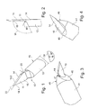
- the Fig. 1 shows a perspective view and Fig. 2 a side view of a blade 12, on which a blade shaft 12 and a blade blade 11 with two cutting edges 18.1, 18.2 are present.
- the two blades of the blade converge symmetrically to the longitudinal axis of the blade in the form of an isosceles triangle and run at an angle 22 of 45 °.
- the cutting edges 18.1, 18.2 are beveled from the rear side 14 forward (to the blade top 16).
- the blade shaft 12 and the blade blade 11 together form a body.
- the body has a continuous, planar rear side surface 14 from the tip of the blade blade to the end of the blade shaft. Opposite the rear surface, the blade shank is formed in a cylindrical surface and the blade blade is formed with its blade top 16.
- the blade top 16 of the blade 11 - in the in Fig. 1 shown embodiment - is parallel to the back 14 of the blade.
- the blade shaft 12 is cut as a in its longitudinal axis Cylinder with a radius R (or with a cylinder diameter 24) is formed.
- the cylinder axis (reference M) lies in the cutting plane.
- the rear surface 14 is in the plane of the halved cylinder.
- the back 15 of the blade shaft and the back 14 of the blade form a common plane.
- the semi-cylindrical design allows accurate centering of the blade in the handle 40 (see 3 and 4 ).
- the surfaces of the blade 10 are formed by grinding of ceramic material, whereby - starting from the contour of the grinding wheels - curves arise, for example, a transition from the blade shaft to the blade, in the Fig. 1 and 2 runs at an obtuse angle W.
- the vertex of transition has - according to Fig. 2 a rounding with a radius R1.
- the existing at the transition from blade to the shaft curves have a radius that is given by the formation of the used grinding wheel. Roundings with radii in the range of approx. 1 mm make sense, in order to keep notch stresses at the transition low.
- FIG. 3 and FIG. 4 show the grip head 41, on the wedge-like or roof edge-like two mutually inclined surfaces 45, 46 are formed.
- the surfaces 45, 46 abut roof edge-like in an edge perpendicular to the axis of the handle edge (47).
- the first inclined surface 45 is an opening 44 (see Fig. 5 ) for inserting the blade shaft 12.
- Fig. 4 shows Fig. 4 in that the inserted blade 10 comes to lie in the opening 44 such that the rear side surface 14 is flush with the first inclined surface 45.
- the scalpel In ophthalmological operations, in particular in a so-called tunnel cut on the eye lens, the scalpel is held according to the invention so that the back surface is approximately parallel (or slightly inclined) to the cornea to come to rest. The tip of the blade can then be inserted and driven in full length into the cornea without the handle head interfering with the cornea.
- the handle 40 is shown at its front end in a side view.
- the shape of the blade shaft 12 (after Fig. 1 semi-cylindrical), the blade 10 is captively glued.
- the length of the blade 10 is dimensioned so that the blade 10, more precisely, the tip of the blade within an imaginary, over the end of the handle head 41 protruding enclosure 50 remains.
- the rear surface 14 is inclined at an angle 48 to the axis of the handle.
- the angle 48 may be between 25 ° and 35 °, preferably it should be 30 °.
- Length of the handle 130 mm and diameter 42 of the handle on the handle head 41: 7 to 8 mm.
- the flattening of the handle is from the cylindrical shape in the flattened part about from a distance from the handle head of one-fifth to one-sixth of the length of the handle. With a length of the handle of 130 mm, thus at about 105 mm from the end of the handle.
- the shape of the flattening is indicated by the section SB in Fig. 5 indicated.
- the material of the handle is a titanium alloy.
- a second embodiment of the blade top (16) is shown with the blades of the blade 11 '.
- This training has no constant cutting thickness.
- the edge on which the blades run towards each other extends over the entire length of the blade and runs out of the blade shaft.
- blade 11 ' is made stronger in the material, which makes this blade shatterproof.
- the curves have a radius that is determined by the contour of the grinding wheel used.
Description
- Die Erfindung betrifft ein Skalpell, insbesondere für ophthalmologische Anwendungen.
- Aus der Druckschrift
DE 19652098 C2 ist ein chirurgisches Instrument bekannt, welches gänzlich (also Griff und Klinge) aus keramischem Werkstoff besteht und im Spritzgießverfahren hergestellt ist. Ein anderes Skalpell besteht aus einer Klinge aus Keramik mit Schneide und Stiel, wobei der Stiel unlösbar im distalen Ende eines Schaftes aus Edelstahl steckt (DE 29919914 U1 ). Solche Skalpelle werden meistens zur einmaligen Verwendung eingesetzt. - Mit der
US 5 718 708 A ist ein ophthalmologisches Instrument veröffentlicht, welches als Schäl- und Schabwerkzeug ausgebildet ist. Das Werkzeug hat einen stumpf auslaufenden Kopf, an der seitliche drei Schneiden angeordnet sind. Der Vorderteil des Werkzeugkopfs ist gegen das Mittelteil mit einem kleinen Winkel abgeknickt. Die Unterseite des abgeknickten Teils trägt eine raue Struktur zum Schaben. Das Instrument ist für flache Schnitte oder flache Einstiche bei Kataraktoperationen nicht zu gebrauchen. Ein für flache Schnitte oder Einstiche geschaffenes Skalpell findet sich in derUS 5 098 438 A . - Die
US 3 325 900 A zeigt ein Skalpell aus einem metallischen Griff und einem metallischen Werkzeugkopf. Im Werkzeugkopf ist ein Klingenhalter ausgebildet, in den ein- oder zweischneidige metallische Klingen einsetzbar sind. - Es ist ein anderes chirurgisches Instrument bekannt, welches mit einer zur Skalpellspitze hin verschiebbaren Schutzhülse ausgestattet ist (
US 2004-0215174 A1 ). Das Instrument ist ein Hightech-Werkzeug und demnach aufwändig ausgebildet und besteht aus einer Vielzahl von Einzelteilen. Die Skalpellklinge ist lösbar befestigt, so dass sie bei Verschleiß ausgewechselt werden kann. - Dokument
US2005/245953 A1 offenbart ein Skalpell nach dem Oberbegriff des Anspruchs 1. - Der Erfindung liegt die Aufgabe zugrunde, ein einfach aufgebautes, mehrfach verwendbares und preisgünstiges Skalpell insbesondere für ophthalmologische Anwendungen anzugeben, mit dem im Besonderen flache Schnitte oder flache Stechbewegungen ausführbar sind.
- Die Aufgabe wird erfindungsgemäß durch die Merkmale des unabhängigen Anspruches gelöst, während den abhängigen Ansprüchen vorteilhafte Weiterbildungen der Erfindung zu entnehmen sind.
- Der Kern der Erfindung liegt darin, dass am Griffkopf keil- oder dachkantenartig zwei gegeneinander geneigte Flächen ausgebildet sind und in einer ersten der geneigten Flächen eine Öffnung zum Einsetzen der Klinge vorhanden ist, wobei die eingesetzte Klinge derart in der Öffnung zu liegen kommt, dass die Rückseitenfläche des aus Klingenschaft und Klingenblatt ausgebildeten Körpers bündig ist mit der ersten geneigten Fläche.
- Durch die bündige Anordnung von Rückseitenfläche mit der ersten geneigten Fläche können auf der Hornhaut des Auges flache Einschnitte oder flache Stechbewegungen ausgeführt werden, die insbesondere bei der Operation an der Augenlinse notwendig sind.
- Weitere vorzugsweise Ausgestaltungen und Ergänzungen werden im Folgenden angesprochen, wobei die Merkmale einzeln oder miteinander gemeinsam verwirklicht sein können.
- Die Öffnung (Bohrung) im Griffkopf ist passend zum Querschnitt des Klingenschafts ausgebildet. Das heißt, dass angepasst an die Ausbildung des Klingenschafts die Öffnung im Querschnitt entsprechend ausgebildet ist.
- Vorzugsweise ist der Klingenschaft als ein Körper ausgebildet, der einen parallel zur Längsachse geschnittenen Zylinder darstellt, wobei die Schnittebene des Körpers in der Längsachse des Zylinders (Zylinderachse) liegt. Die Rückseitenfläche entspricht der Ebene des halbierten Zylinders. Eine (halb-)zylindrische Ausbildung erlaubt eine genaue Zentrierung der Klinge im Griff. Des weiteren wird das Einsetzen des Klingenschafts und das Befestigen (in einem Klebevorgang) vereinfacht, da der Kleber sich gleichmäßig auf der zylindrischen Oberfläche verteilt; es entstehen keine Ecken.
- Ein wesentlicher Punkt ist, dass die Länge der Klinge so bemessen ist, dass die Klinge innerhalb einer gedachten, über das Ende des Griffkopfs hinausragenden Umhüllung verbleibt. Die Länge der Klinge steht also an keinem Punkt über der am Ende des Griffkopfs hinausragenden (gedachten) Umhüllung über. Dies hat den Vorteil, dass die Klinge eines auf einem Tablett liegenden Skalpells nicht die Unterlage berührt. Es kann somit nicht zu einer Kontamination oder einer Beschädigung durch die Berührung mit der Unterlage kommen.
- Die erste geneigte Fläche am Griffkopf sollte gegen die Längsachse des Griffs mit einem Winkel zwischen 25° und 35° geneigt sein, vorzugsweise mit einem Winkel von 30°.
- Bei der 'Normalausführung' des Skalpells sind an der Klinge zwei Schneiden ausgebildet. Bei einer solchen Ausführung laufen die beiden Schneiden der Klinge symmetrisch zur Längsachse der Klinge in Form eines gleichschenkligen Dreiecks zusammen. Die Form des gleichschenkligen Dreiecks würde in der symmetrischen Ausführung in einem Winkel von 45° auslaufen.
- Die Schneidkanten der Klinge sind von der Rückseitenfläche her zur Klingenoberseite angeschrägt. Es sind besonders zwei Ausführungen untersucht worden. Bei einer ersten beträgt der Schneidkantenwinkel ca. 45°; in einer zweiten Klingenform hat der Winkel den Wert von ca. 30°. Die Ausbildungen sind in der Figurenbeschreibung näher erläutert.
- Ein Schneidkantenwinkel von ca. 45° wird hergestellt bei Klingen, die eine bestimmte Dicke haben. Wird der Schneidkantenwinkel verringert, beispielsweise auf 30°, dann entsteht eine sehr flache Ausbildung der Schneide. Oberseite und Rückseite der Klinge sind nicht mehr parallel. Bei dieser Ausbildung hat die Klinge keine konstante Schneidendicke, da die Kanten auf den Schneiden zueinander hinlaufen und eine gemeinsame, in der Mitte der Klinge liegende 'Mittellinie' bilden (siehe
Fig. 6 ). - Die Klinge besteht aus Keramik (Zirkonoxid, Aluminiumoxid oder Mischoxid=Keramik) und wird durch Schleif- und Polierprozesse bearbeitet. Zirkonoxid hat sich als besonders geeignet herausgestellt. Der keramische Ausgangswerkstoff wird in einem HIP-Vorgang (heißisostatisches Pressen) behandelt und ist danach porenfrei, wodurch er sich sehr gut sterilisieren lässt. Skalpelle aus Zirkonoxid vereinen hohe Härte und Verschleißfestigkeit mit geringerer Stoßempfindlichkeit.
- Andere Klingenwerkstoffe sind für die Herstellung des Skalpells natürlich ebenso geeignet, wobei auch Diamant infrage kommt. Diamant kann aufgrund seiner hohen Härte und der daraus resultierenden Verschleißfestigkeit mehrmals eingesetzt werden. Allerdings ist Diamant sehr stoßempfindlich und zusätzlich sehr teuer.
- Metall-Klingen sind nur beschränkt geeignet, da sie nach einmaligem Gebrauch nicht mehr verwendbar sind.
- Die Klinge ist an ihrem Schaft in den Griffkopf unverlierbar eingeklebt. Durch den satten Sitz des Klingenschafts in der Öffnung im Griffkopf genügt ein Tropfen Sekundenkleber, um den Sitz und die Festigkeit herzustellen. Das so hergestellte Skalpell ist mehrfach sterilisierbar und damit mehrfach verwendbar.
- Der Durchmesser des (halb-)zylindrischen Klingenschafts ist beispielsweise 4 mm. Die Dicke der Schneide: 0,2 bis 0,3 mm; die Schneidkanten sind gegen die Rückseitenfläche mit einem Winkel von ca. 45° angeschrägt. Bei Einsatz präzise arbeitender Schleifmaschinen entstehen Flächen mit hoher Glätte, so dass die Flächen nicht notwendigerweise weiter poliert werden müssen. Allerdings kann sich nach dem Schleifvorgang noch ein Polierschritt für die Schneidenflächen anschließen mit Diamantschleifscheiben mit Körnungen im µm-Bereich.
- Die vorliegende Erfindung ist nicht auf die vorstehend beschriebenen Ausführungsformen beschränkt, sondern umfasst auch alle im Sinne der Erfindung gleichwirkenden Ausführungsformen. Skalpelle mit nur einer Schneide an der Klinge sollen ebenso erfasst sein. Weiterhin lässt sich die Erfindung beispielsweise grundsätzlich auch auf alle mikrochirurgischen Skalpelle anwenden.
- Weitere Einzelheiten und Vorteile der Erfindung werden Ausführungsbeispielen anhand von Figuren erläutert. Sie zeigen im Einzelnen
-
Figur 1 : eine perspektivische Darstellung einer ersten Klinge; -
Figur 2 : ein Seitenansicht einer Klinge; -
Figur 3 : eine erste perspektivische Darstellung Klinge im Griffkopf; -
Figur 4 : eine zweite perspektivische Darstellung Klinge im Griffkopf; -
Figur 5 : ein Seitenansicht der Klinge in Griffkopf und -
Figur 6 : eine zweite Klingenblattform. - Die
Fig. 1 zeigt eine perspektivische Darstellung undFig. 2 eine Seitenansicht einer Klinge 12, an der ein Klingenschaft 12 und ein Klingenblatt 11 mit zwei Schneiden 18.1, 18.2 vorhanden sind. Die beiden Schneiden der Klinge laufen symmetrisch zur Längsachse der Klinge in Form eines gleichschenkligen Dreiecks zusammen und laufen in einem Winkel 22 von 45° aus. Die Schneiden 18.1, 18.2 sind von der Rückseite 14 her nach vorn (zur Klingenoberseite 16) angeschrägt. Der Klingenschaft 12 und das Klingenblatt 11 bilden gemeinsam einen Körper. Der Körper hat von der Spitze des Klingenblattes bis zum Ende des Klingenschafts eine durchgehende, ebene Rückseitenfläche 14. Der Rückseitenfläche gegenüberliegend ist der Klingenschaft in einer zylindrischen Fläche und das Klingenblatt mit seiner Klingenoberseite 16 ausgebildet. - Die Klingenoberseite 16 der Klinge 11 - in der in
Fig. 1 gezeigten Ausführungsform - liegt parallel zur Rückseite 14 der Klinge. Der Klingenschaft 12 ist als ein in seiner Längsachse geschnittener Zylinder mit einem Radius R (bzw. mit einem Zylinder-Durchmesser 24) ausgebildet. Die Zylinderachse (Bezugszeichen M) liegt in der Schnittebene. - Die Rückseitenfläche 14 liegt in der Ebene des halbierten Zylinders. Die Rückseite 15 des Klingenschafts und die Rückseite 14 der Klinge bilden eine gemeinsame Ebene. Die halbzylindrische Ausbildung erlaubt eine genaue Zentrierung der Klinge im Griff 40 (siehe
Fig. 3 und 4 ). Die Flächen der Klinge 10 werden durch Schleifen aus keramischem Werkstoff herausgebildet, wodurch - ausgehend von der Kontur der Schleifscheiben - Rundungen entstehen, beispielsweise ein Übergang vom Klingenschaft zur Klinge, der in denFig. 1 und 2 in einem stumpfen Winkel W verläuft. Der Scheitel des Übergangs hat - gemäßFig. 2 - eine Rundung mit einem Radius R1. Die am Übergang von Klinge zum Schaft vorhandenen Rundungen haben einen Radius, der durch die Ausbildung der benutzten Schleifscheibe gegeben ist. Es sind Rundungen mit Radien im Bereich von ca. 1 mm sinnvoll, um Kerbspannungen am Übergang gering zu halten. -
Fig. 3 und Fig. 4 zeigen den Griffkopf 41, an dem keilartig oder dachkantenartig zwei gegeneinander geneigte Flächen 45, 46 ausgebildet sind. Die Flächen 45, 46 stoßen dachkantenartig in einer senkrecht zur Achse des Griffs liegenden Kante (47) zusammen. In der ersten geneigte Fläche 45 ist eine Öffnung 44 (sieheFig. 5 ) zum Einsetzen des Klingenschafts 12 vorhanden. Insbesondere zeigtFig. 4 , dass die eingesetzte Klinge 10 derart in der Öffnung 44 zu liegen kommt, dass die Rückseitenfläche 14 bündig mit der ersten geneigten Fläche 45 ist. - Bei ophthalmologischen Operationen, insbesondere bei einem sogenannten Tunnelschnitt an der Augenlinse wird das Skalpell nach der Erfindung so gehalten, dass die Rückseitenfläche etwa parallel (oder wenig geneigt) zur Hornhaut zu liegen kommt. Die Spitze der Klinge kann sodann in voller Länge in die Hornhaut eingeführt und vorgetrieben werden, ohne dass der Griffkopf störend die Hornhaut berührt.
- In der
Fig. 5 wird der Griff 40 an seinem vorderen Ende in einer Seitenansicht gezeigt. In der Öffnung 44, die die Form des Klingenschafts 12 (nachFig. 1 halbzylindrisch) hat, ist die Klinge 10 unverlierbar eingeklebt. Die Länge der Klinge 10 ist so bemessen, dass die Klinge 10, genauer gesagt, die Spitze der Klinge innerhalb einer gedachten, über das Ende des Griffkopfs 41 hinausragenden Umhüllung 50 verbleibt. Die Rückseitenfläche 14 liegt in einem Winkel 48 geneigt gegen die Achse des Griffs. Der Winkel 48 kann zwischen 25° und 35° liegen, vorzugsweise soll er 30° betragen. - Als typische Dimensionen des Griffs können genannt werden: Länge des Griffs: 130 mm und Durchmesser 42 des Griffs am Griffkopf 41: 7 bis 8 mm. Am Griffkopf ist der Griff zylindrisch ausgebildet, was durch den Schnitt SA in
Fig. 5 angedeutet ist. Zum Ende des Griffs ist eine leichte Abflachung des Zylinders ausgebildet, was den Vorteil hat, dass das Skalpell bei Auflegen auf eine Unterlage in eine eindeutige Position rollen kann. Die Abflachung des Griffs geht von der Zylinderform über in den abgeflachten Teil etwa ab einem Abstand vom Griffkopf von einem Fünftel bis einem Sechstel der Länge des Griffs. Bei einer Länge des Griffs von 130 mm, somit bei etwa 105 mm vom Ende des Griffs. Die Form der Abflachung wird durch den Schnitt SB inFig. 5 angedeutet. Vorzugsweise ist das Material des Griffs eine Titan-Legierung. - In
Fig. 6 wird eine zweite Ausbildung der Klingenoberseite (16) mit den Schneiden der Klinge 11' gezeigt. Diese Ausbildung hat keine konstante Schneidendicke. Die Kante, an der die Schneiden zueinander hinlaufen, erstreckt sich über die gesamte Länge der Klinge und läuft am Klingenschaft aus. Die inFig. 6 gezeigte Klinge 11' ist im Material stärker ausgebildet, was diese Klinge bruchsicherer macht. Obwohl inFig. 6 dies nicht besonders deutlich wird, laufen die Flächen der Schneiden am Übergang von Klinge 11' zum Klingenschaft (vergleichbar mitFig. 2 ) gerundet aus. Die Rundungen haben einen Radius, der von der Kontur der benutzten Schleifscheibe vorgegeben ist. -
- 10, 10'
- Klinge
- 11 11'
- Klingenblatt, zweite Blattform
- 12
- Klingenschaft
- 14
- Rückseitenfläche
- 15
- Rückseite Klingenschaft
- 16
- Klingenoberseite
- 18.1 18.2
- linke, rechte Schneide
- 20
- Winkel Anschrägung
- 22
- Winkel gleichschenkliges Dreieck
- 24
- Durchmesser
- 25
- Zylinderachse
- M
- Mittelpunkt Zylinder
- R
- Radius Klingenschaft
- R1
- Rundung
- W
- Winkel
- 40
- Griff
- 41
- Griffkopf
- 42
- Durchmesser (Umhüllung) am Griffkopf
- 44
- Öffnung, Bohrung (rund oder quadratisch)
- 45
- erste geneigte Fläche (Keil)
- 46
- zweite geneigte Fläche
- 47
- Kante
- 49
- Abflachung
- 48
- Winkel Neigung erste Fläche zur Achse Griff
- 50
- Umhüllung
- SA
- Schnitt nähe Griffkopf
- SB
- Schnitt nähe Griffende (mit Abflachung)
Claims (10)
- Skalpell, insbesondere für ophthalmologische Anwendungen, umfassend einen Griff und eine Klinge, wobei in einem Griffkopf (41) des Griffs (40) die aus einem Klingenschaft (12) und einem Klingenblatt (11, 11') bestehende Klinge (10) eingesetzt ist, und am Klingenblatt (11,11') mindestens eine Schneide (18.1, 18.2) ausgebildet ist, wobei• der Klingenschaft (12) gemeinsam mit dem Klingenblatt (11, 11') als ein Körper ausgebildet ist,dadurch gekennzeichnet, dass
an dem Körper eine durchgehende ebene Rückseitenfläche (14) ausgebildet ist,• wobei die der Rückseitenfläche (14) gegenüberliegende Vorderseite des Körpers im Bereich des Klingenschafts (12) eine zylindrische Fläche und im Bereich des Klingenblatts (11, 11') die Klingenoberseite bildet, und• der Griffkopf (41) an seinem Ende zwei gegeneinander geneigte Flächen (45, 46) hat, die dachkantenartig In einer senkrecht zur Achse des Griffs (40) liegenden Kante (47) zusammenstoßen, und• wobei in einer ersten der geneigten Flächen (45) eine Öffnung (44) zum Einsetzen des Klingenschafts (10, 12) vorhanden ist, und die eingesetzte Klinge (10) derart in der Öffnung (44) zu liegen kommt, dass die ebene Rückseitenfläche (14) bündig ist mit der ersten geneigten Fläche (45). - Skalpell nach Anspruch 1, dadurch gekennzeichnet, dass der Klingenschaft (12) als ein Körper ausgebildet ist, der einen parallel zur Längsachse geschnittenen Zylinder (M, R) darstellt, welcher seine Schnittebene in der Längsachse des Zylinders hat.
- Skalpell nach einem der vorhergehenden Ansprüche, dadurch gekennzeichnet, dass die Länge der Klinge (10) so bemessen ist, dass die Klinge (10) innerhalb einer gedachten, über das Ende des Griffkopfs (41) hinausragenden Umhüllung (50) verbleibt.
- Skalpell nach einem der vorhergehenden Ansprüche, dadurch gekennzeichnet, dass die erste geneigte Fläche (45) am Griffkopf (41) gegen die Längsachse des Griffs (40) mit einem Winkel (48) zwischen 25° und 35° geneigt ist, vorzugsweise mit einem Winkel von 30°.
- Skalpell nach einem der vorstehenden Ansprüche, dadurch gekennzeichnet, dass an der Klinge (10) zwei Schneiden (18.1, 18.2) ausgebildet sind.
- Skalpell nach vorstehendem Anspruch, dadurch gekennzeichnet, dass die Schneiden (18.1, 18.2) der Klinge (10) symmetrisch zur Längsachse der Klinge (10) in Form eines gleichschenkligen Dreiecks (22) zusammenlaufen.
- Skalpell nach vorstehendem Anspruch, dadurch gekennzeichnet, dass die Form des gleichschenkligen Dreiecks in einem Winkel (22) von 45° ausläuft.
- Skalpell nach vorstehendem Anspruch, dadurch gekennzeichnet, dass die Schneidkanten (18.1, 18.2) von der Rückseitenfläche (14) her zur Klingenoberseite (16) angeschrägt sind.
- Skalpell nach einem der vorhergehenden Ansprüche, dadurch gekennzeichnet, dass die Klinge (12) aus Keramik besteht.
- Skalpell nach einem der vorhergehenden Ansprüche, dadurch gekennzeichnet, dass die Klinge (12) in den Griffkopf (41) eingeklebt ist.
Priority Applications (2)
| Application Number | Priority Date | Filing Date | Title |
|---|---|---|---|
| SI201030569T SI2448503T1 (sl) | 2009-06-29 | 2010-06-23 | Skalpel, še zlasti za oftalmološko uporabo |
| PL10724540T PL2448503T3 (pl) | 2009-06-29 | 2010-06-23 | Skalpel, w szczególności do zabiegów okulistycznych |
Applications Claiming Priority (2)
| Application Number | Priority Date | Filing Date | Title |
|---|---|---|---|
| DE102009030874A DE102009030874A1 (de) | 2009-06-29 | 2009-06-29 | Skalpell, insbesondere für ophthalmologische Anwendungen |
| PCT/EP2010/058896 WO2011000752A1 (de) | 2009-06-29 | 2010-06-23 | Skalpell, insbesondere für ophthalmologische anwendungen |
Publications (2)
| Publication Number | Publication Date |
|---|---|
| EP2448503A1 EP2448503A1 (de) | 2012-05-09 |
| EP2448503B1 true EP2448503B1 (de) | 2013-12-25 |
Family
ID=42734690
Family Applications (1)
| Application Number | Title | Priority Date | Filing Date |
|---|---|---|---|
| EP10724540.9A Active EP2448503B1 (de) | 2009-06-29 | 2010-06-23 | Skalpell, insbesondere für ophthalmologische anwendungen |
Country Status (14)
| Country | Link |
|---|---|
| US (1) | US8518068B2 (de) |
| EP (1) | EP2448503B1 (de) |
| JP (1) | JP5560327B2 (de) |
| KR (1) | KR20120062686A (de) |
| BR (1) | BRPI1010159A2 (de) |
| CA (1) | CA2764261A1 (de) |
| DE (1) | DE102009030874A1 (de) |
| ES (1) | ES2452571T3 (de) |
| HR (1) | HRP20140286T1 (de) |
| MX (1) | MX2011013911A (de) |
| PL (1) | PL2448503T3 (de) |
| PT (1) | PT2448503E (de) |
| SI (1) | SI2448503T1 (de) |
| WO (1) | WO2011000752A1 (de) |
Cited By (1)
| Publication number | Priority date | Publication date | Assignee | Title |
|---|---|---|---|---|
| CN109661206A (zh) * | 2016-08-29 | 2019-04-19 | 马尼株式会社 | 医用刀具 |
Families Citing this family (6)
| Publication number | Priority date | Publication date | Assignee | Title |
|---|---|---|---|---|
| US8642122B2 (en) | 2009-01-12 | 2014-02-04 | The Gillette Company | Formation of thin uniform coatings on blade edges using isostatic press |
| US8628821B2 (en) * | 2009-01-12 | 2014-01-14 | The Gillette Company | Formation of thin uniform coatings on blade edges using isostatic press |
| US9872799B2 (en) * | 2012-04-24 | 2018-01-23 | The Regents Of The University Of Colorado, A Body Corporate | Intraocular device for dual incisions |
| WO2017112893A1 (en) * | 2015-12-23 | 2017-06-29 | The Regents Of The University Of Colorado, A Body Corporate | An ophthalmic knife and methods of use |
| WO2022229960A1 (en) * | 2021-04-29 | 2022-11-03 | Orca Surgical Ltd. | Apparatus and method for removing tissue |
| WO2023177761A2 (en) | 2022-03-16 | 2023-09-21 | Sight Sciences, Inc. | Devices and methods for intraocular tissue manipulation |
Family Cites Families (12)
| Publication number | Priority date | Publication date | Assignee | Title |
|---|---|---|---|---|
| US3325900A (en) * | 1964-04-30 | 1967-06-20 | Johan F Sohlberg | Surgical blade holder for dentistry |
| JPH0423536Y2 (de) * | 1987-09-17 | 1992-06-02 | ||
| US5098438A (en) * | 1990-08-23 | 1992-03-24 | Siepser Steven B | Procedures for intraocular surgery |
| US5718708A (en) * | 1996-04-01 | 1998-02-17 | Webb; Nicholas J. | Ophthalmic instrument for removing foreign objects |
| DE19652098C2 (de) | 1996-12-14 | 2001-04-19 | Slg Kunststoff Fabrik Und Form | Chirurgisches Instrument und Verfahren zu seiner Herstellung |
| DE29919917U1 (de) | 1999-11-12 | 2000-01-20 | Merlaku Kastriot | Netz-Steuereinheit für fernbedienbare Geräte mit Stand-By Modus |
| DE29919914U1 (de) | 1999-11-12 | 2000-01-27 | Wolf Gmbh Richard | Strikturskalpell |
| US20040181950A1 (en) * | 2003-03-17 | 2004-09-23 | Rodgers Murray Steven | Alignment of microkeratome blade to blade handle |
| US7022128B2 (en) * | 2003-04-22 | 2006-04-04 | Becton, Dickinson And Company | Surgical knife safety handle |
| US7055248B2 (en) * | 2004-04-30 | 2006-06-06 | Becton, Dickinson And Company | Surgical knife blade attachment and method for using same |
| JP2005334054A (ja) * | 2004-05-24 | 2005-12-08 | Kai R & D Center Co Ltd | 医療用刃物 |
| CN101674783B (zh) * | 2007-04-27 | 2014-07-02 | 马尼株式会社 | 剥离用刀 |
-
2009
- 2009-06-29 DE DE102009030874A patent/DE102009030874A1/de not_active Withdrawn
-
2010
- 2010-06-23 US US13/321,446 patent/US8518068B2/en not_active Expired - Fee Related
- 2010-06-23 CA CA2764261A patent/CA2764261A1/en not_active Abandoned
- 2010-06-23 EP EP10724540.9A patent/EP2448503B1/de active Active
- 2010-06-23 PT PT107245409T patent/PT2448503E/pt unknown
- 2010-06-23 MX MX2011013911A patent/MX2011013911A/es not_active Application Discontinuation
- 2010-06-23 PL PL10724540T patent/PL2448503T3/pl unknown
- 2010-06-23 SI SI201030569T patent/SI2448503T1/sl unknown
- 2010-06-23 KR KR1020127002390A patent/KR20120062686A/ko not_active Application Discontinuation
- 2010-06-23 JP JP2012516715A patent/JP5560327B2/ja not_active Expired - Fee Related
- 2010-06-23 WO PCT/EP2010/058896 patent/WO2011000752A1/de active Application Filing
- 2010-06-23 ES ES10724540.9T patent/ES2452571T3/es active Active
- 2010-06-23 BR BRPI1010159A patent/BRPI1010159A2/pt not_active IP Right Cessation
-
2014
- 2014-03-25 HR HRP20140286AT patent/HRP20140286T1/hr unknown
Cited By (1)
| Publication number | Priority date | Publication date | Assignee | Title |
|---|---|---|---|---|
| CN109661206A (zh) * | 2016-08-29 | 2019-04-19 | 马尼株式会社 | 医用刀具 |
Also Published As
| Publication number | Publication date |
|---|---|
| CA2764261A1 (en) | 2011-01-06 |
| PL2448503T3 (pl) | 2014-07-31 |
| BRPI1010159A2 (pt) | 2016-03-29 |
| PT2448503E (pt) | 2014-03-17 |
| JP5560327B2 (ja) | 2014-07-23 |
| JP2012531231A (ja) | 2012-12-10 |
| MX2011013911A (es) | 2012-05-22 |
| US20120089165A1 (en) | 2012-04-12 |
| KR20120062686A (ko) | 2012-06-14 |
| HRP20140286T1 (hr) | 2014-06-06 |
| US8518068B2 (en) | 2013-08-27 |
| DE102009030874A1 (de) | 2010-12-30 |
| WO2011000752A1 (de) | 2011-01-06 |
| EP2448503A1 (de) | 2012-05-09 |
| SI2448503T1 (sl) | 2014-04-30 |
| ES2452571T3 (es) | 2014-04-02 |
Similar Documents
| Publication | Publication Date | Title |
|---|---|---|
| EP2448503B1 (de) | Skalpell, insbesondere für ophthalmologische anwendungen | |
| US4990148A (en) | Thin footplate rongeur | |
| DE2925089A1 (de) | Gelenkprothese, insbesondere kuenstliches oberschenkelhueftgelenk | |
| DE202005021068U1 (de) | Chirurgisches Maulinstrument | |
| EP0928164A1 (de) | Knochenfräser | |
| DE102017111634B3 (de) | Medizinische Schneidevorrichtung mit rotierendem Messer | |
| WO2017133967A1 (de) | Minimalinvasives inzisionsinstrument mit geführter mehrfachschneide | |
| DE202006018587U1 (de) | Chirurgisches Instrument zur Implantierung eines Drahtes, vorzugsweise in einen Knochen | |
| EP2249139B1 (de) | Einweg-Knorpelschneider | |
| DE4416377A1 (de) | Vorrichtung zum Austrennen von Endoprothesen | |
| EP1513654B1 (de) | Schraubendreher mit schraubenhalter | |
| EP2563243B1 (de) | Knochenbiopsiefräser | |
| EP3136989B1 (de) | Chirurgischer clip | |
| EP1752119B1 (de) | Schneidklingenhalter für eine mikrochirurgische Schneidanordnung, insbesondere eine solche für die refraktive Augenchirurgie | |
| DE202017103219U1 (de) | Medizinische Schneidevorrichtung mit rotierendem Messer | |
| DE102005016380B4 (de) | Chirurgisches Instrument | |
| EP3402418B1 (de) | Medizinisches raspelinstrument | |
| DE102012009142B3 (de) | Pinzette | |
| DE202016008660U1 (de) | Zangenlöffelanordnung für eine Biopsiezange und Biopsiezange zur Entnahme von Hirngewebeproben | |
| EP1281359A1 (de) | Chirurgisches Messer | |
| EP1808132B1 (de) | Instrumentarium zum Formen eines Zwischenwirbelraums | |
| EP3468499B1 (de) | Bohrdrahthülse | |
| DE202023100902U1 (de) | Chirurgische Schneidevorrichtung für die Otologie | |
| DE3728934B4 (de) | Anpressvorrichtung zum Anpressen eines Implantats | |
| DE202017101594U1 (de) | Chirurgisches Instrument |
Legal Events
| Date | Code | Title | Description |
|---|---|---|---|
| PUAI | Public reference made under article 153(3) epc to a published international application that has entered the european phase |
Free format text: ORIGINAL CODE: 0009012 |
|
| 17P | Request for examination filed |
Effective date: 20120130 |
|
| AK | Designated contracting states |
Kind code of ref document: A1 Designated state(s): AL AT BE BG CH CY CZ DE DK EE ES FI FR GB GR HR HU IE IS IT LI LT LU LV MC MK MT NL NO PL PT RO SE SI SK SM TR |
|
| DAX | Request for extension of the european patent (deleted) | ||
| GRAP | Despatch of communication of intention to grant a patent |
Free format text: ORIGINAL CODE: EPIDOSNIGR1 |
|
| INTG | Intention to grant announced |
Effective date: 20130709 |
|
| GRAS | Grant fee paid |
Free format text: ORIGINAL CODE: EPIDOSNIGR3 |
|
| GRAA | (expected) grant |
Free format text: ORIGINAL CODE: 0009210 |
|
| AK | Designated contracting states |
Kind code of ref document: B1 Designated state(s): AL AT BE BG CH CY CZ DE DK EE ES FI FR GB GR HR HU IE IS IT LI LT LU LV MC MK MT NL NO PL PT RO SE SI SK SM TR |
|
| REG | Reference to a national code |
Ref country code: GB Ref legal event code: FG4D Free format text: NOT ENGLISH |
|
| REG | Reference to a national code |
Ref country code: CH Ref legal event code: EP |
|
| REG | Reference to a national code |
Ref country code: AT Ref legal event code: REF Ref document number: 646134 Country of ref document: AT Kind code of ref document: T Effective date: 20140115 |
|
| REG | Reference to a national code |
Ref country code: IE Ref legal event code: FG4D Free format text: LANGUAGE OF EP DOCUMENT: GERMAN |
|
| REG | Reference to a national code |
Ref country code: DE Ref legal event code: R096 Ref document number: 502010005764 Country of ref document: DE Effective date: 20140213 |
|
| REG | Reference to a national code |
Ref country code: CH Ref legal event code: NV Representative=s name: R. A. EGLI AND CO. PATENTANWAELTE, CH |
|
| REG | Reference to a national code |
Ref country code: NL Ref legal event code: T3 |
|
| REG | Reference to a national code |
Ref country code: RO Ref legal event code: EPE |
|
| REG | Reference to a national code |
Ref country code: PT Ref legal event code: SC4A Free format text: AVAILABILITY OF NATIONAL TRANSLATION Effective date: 20140311 |
|
| REG | Reference to a national code |
Ref country code: HR Ref legal event code: TUEP Ref document number: P20140286 Country of ref document: HR |
|
| REG | Reference to a national code |
Ref country code: ES Ref legal event code: FG2A Ref document number: 2452571 Country of ref document: ES Kind code of ref document: T3 Effective date: 20140402 |
|
| REG | Reference to a national code |
Ref country code: EE Ref legal event code: FG4A Ref document number: E008826 Country of ref document: EE Effective date: 20140217 |
|
| PG25 | Lapsed in a contracting state [announced via postgrant information from national office to epo] |
Ref country code: FI Free format text: LAPSE BECAUSE OF FAILURE TO SUBMIT A TRANSLATION OF THE DESCRIPTION OR TO PAY THE FEE WITHIN THE PRESCRIBED TIME-LIMIT Effective date: 20131225 Ref country code: SE Free format text: LAPSE BECAUSE OF FAILURE TO SUBMIT A TRANSLATION OF THE DESCRIPTION OR TO PAY THE FEE WITHIN THE PRESCRIBED TIME-LIMIT Effective date: 20131225 Ref country code: NO Free format text: LAPSE BECAUSE OF FAILURE TO SUBMIT A TRANSLATION OF THE DESCRIPTION OR TO PAY THE FEE WITHIN THE PRESCRIBED TIME-LIMIT Effective date: 20140325 Ref country code: LT Free format text: LAPSE BECAUSE OF FAILURE TO SUBMIT A TRANSLATION OF THE DESCRIPTION OR TO PAY THE FEE WITHIN THE PRESCRIBED TIME-LIMIT Effective date: 20131225 |
|
| REG | Reference to a national code |
Ref country code: LT Ref legal event code: MG4D |
|
| REG | Reference to a national code |
Ref country code: SK Ref legal event code: T3 Ref document number: E 15939 Country of ref document: SK |
|
| REG | Reference to a national code |
Ref country code: HR Ref legal event code: T1PR Ref document number: P20140286 Country of ref document: HR |
|
| PG25 | Lapsed in a contracting state [announced via postgrant information from national office to epo] |
Ref country code: IS Free format text: LAPSE BECAUSE OF FAILURE TO SUBMIT A TRANSLATION OF THE DESCRIPTION OR TO PAY THE FEE WITHIN THE PRESCRIBED TIME-LIMIT Effective date: 20140425 |
|
| REG | Reference to a national code |
Ref country code: PL Ref legal event code: T3 |
|
| PG25 | Lapsed in a contracting state [announced via postgrant information from national office to epo] |
Ref country code: CY Free format text: LAPSE BECAUSE OF FAILURE TO SUBMIT A TRANSLATION OF THE DESCRIPTION OR TO PAY THE FEE WITHIN THE PRESCRIBED TIME-LIMIT Effective date: 20131225 |
|
| REG | Reference to a national code |
Ref country code: DE Ref legal event code: R097 Ref document number: 502010005764 Country of ref document: DE |
|
| REG | Reference to a national code |
Ref country code: HU Ref legal event code: AG4A Ref document number: E020545 Country of ref document: HU |
|
| PG25 | Lapsed in a contracting state [announced via postgrant information from national office to epo] |
Ref country code: DK Free format text: LAPSE BECAUSE OF FAILURE TO SUBMIT A TRANSLATION OF THE DESCRIPTION OR TO PAY THE FEE WITHIN THE PRESCRIBED TIME-LIMIT Effective date: 20131225 |
|
| PLBE | No opposition filed within time limit |
Free format text: ORIGINAL CODE: 0009261 |
|
| STAA | Information on the status of an ep patent application or granted ep patent |
Free format text: STATUS: NO OPPOSITION FILED WITHIN TIME LIMIT |
|
| 26N | No opposition filed |
Effective date: 20140926 |
|
| REG | Reference to a national code |
Ref country code: DE Ref legal event code: R097 Ref document number: 502010005764 Country of ref document: DE Effective date: 20140926 |
|
| REG | Reference to a national code |
Ref country code: HR Ref legal event code: PBON Ref document number: P20140286 Country of ref document: HR Effective date: 20140623 |
|
| PG25 | Lapsed in a contracting state [announced via postgrant information from national office to epo] |
Ref country code: CZ Free format text: LAPSE BECAUSE OF NON-PAYMENT OF DUE FEES Effective date: 20140623 Ref country code: MC Free format text: LAPSE BECAUSE OF FAILURE TO SUBMIT A TRANSLATION OF THE DESCRIPTION OR TO PAY THE FEE WITHIN THE PRESCRIBED TIME-LIMIT Effective date: 20131225 Ref country code: LU Free format text: LAPSE BECAUSE OF FAILURE TO SUBMIT A TRANSLATION OF THE DESCRIPTION OR TO PAY THE FEE WITHIN THE PRESCRIBED TIME-LIMIT Effective date: 20140623 |
|
| REG | Reference to a national code |
Ref country code: EE Ref legal event code: MM4A Ref document number: E008826 Country of ref document: EE Effective date: 20140630 |
|
| GBPC | Gb: european patent ceased through non-payment of renewal fee |
Effective date: 20140623 |
|
| PG25 | Lapsed in a contracting state [announced via postgrant information from national office to epo] |
Ref country code: LV Free format text: LAPSE BECAUSE OF NON-PAYMENT OF DUE FEES Effective date: 20140623 |
|
| REG | Reference to a national code |
Ref country code: SK Ref legal event code: MM4A Ref document number: E 15939 Country of ref document: SK Effective date: 20140623 |
|
| REG | Reference to a national code |
Ref country code: IE Ref legal event code: MM4A |
|
| REG | Reference to a national code |
Ref country code: FR Ref legal event code: ST Effective date: 20150227 |
|
| PG25 | Lapsed in a contracting state [announced via postgrant information from national office to epo] |
Ref country code: NL Free format text: LAPSE BECAUSE OF NON-PAYMENT OF DUE FEES Effective date: 20150101 |
|
| REG | Reference to a national code |
Ref country code: SI Ref legal event code: KO00 Effective date: 20150213 Ref country code: PT Ref legal event code: MM4A Free format text: LAPSE DUE TO NON-PAYMENT OF FEES Effective date: 20150323 |
|
| PG25 | Lapsed in a contracting state [announced via postgrant information from national office to epo] |
Ref country code: EE Free format text: LAPSE BECAUSE OF NON-PAYMENT OF DUE FEES Effective date: 20140630 Ref country code: PT Free format text: LAPSE BECAUSE OF NON-PAYMENT OF DUE FEES Effective date: 20150323 Ref country code: BG Free format text: LAPSE BECAUSE OF NON-PAYMENT OF DUE FEES Effective date: 20150331 Ref country code: HU Free format text: LAPSE BECAUSE OF NON-PAYMENT OF DUE FEES Effective date: 20140624 Ref country code: IE Free format text: LAPSE BECAUSE OF NON-PAYMENT OF DUE FEES Effective date: 20140623 Ref country code: SK Free format text: LAPSE BECAUSE OF NON-PAYMENT OF DUE FEES Effective date: 20140623 Ref country code: IT Free format text: LAPSE BECAUSE OF NON-PAYMENT OF DUE FEES Effective date: 20140623 |
|
| PG25 | Lapsed in a contracting state [announced via postgrant information from national office to epo] |
Ref country code: HR Free format text: LAPSE BECAUSE OF NON-PAYMENT OF DUE FEES Effective date: 20140623 Ref country code: GB Free format text: LAPSE BECAUSE OF NON-PAYMENT OF DUE FEES Effective date: 20140623 Ref country code: SI Free format text: LAPSE BECAUSE OF NON-PAYMENT OF DUE FEES Effective date: 20140624 Ref country code: FR Free format text: LAPSE BECAUSE OF NON-PAYMENT OF DUE FEES Effective date: 20140630 |
|
| REG | Reference to a national code |
Ref country code: ES Ref legal event code: FD2A Effective date: 20150724 |
|
| REG | Reference to a national code |
Ref country code: PL Ref legal event code: LAPE |
|
| PG25 | Lapsed in a contracting state [announced via postgrant information from national office to epo] |
Ref country code: ES Free format text: LAPSE BECAUSE OF NON-PAYMENT OF DUE FEES Effective date: 20140624 |
|
| PGFP | Annual fee paid to national office [announced via postgrant information from national office to epo] |
Ref country code: CH Payment date: 20150721 Year of fee payment: 6 |
|
| PG25 | Lapsed in a contracting state [announced via postgrant information from national office to epo] |
Ref country code: PL Free format text: LAPSE BECAUSE OF NON-PAYMENT OF DUE FEES Effective date: 20140623 |
|
| PGFP | Annual fee paid to national office [announced via postgrant information from national office to epo] |
Ref country code: DE Payment date: 20151027 Year of fee payment: 6 |
|
| PG25 | Lapsed in a contracting state [announced via postgrant information from national office to epo] |
Ref country code: MT Free format text: LAPSE BECAUSE OF FAILURE TO SUBMIT A TRANSLATION OF THE DESCRIPTION OR TO PAY THE FEE WITHIN THE PRESCRIBED TIME-LIMIT Effective date: 20131225 |
|
| PG25 | Lapsed in a contracting state [announced via postgrant information from national office to epo] |
Ref country code: SM Free format text: LAPSE BECAUSE OF FAILURE TO SUBMIT A TRANSLATION OF THE DESCRIPTION OR TO PAY THE FEE WITHIN THE PRESCRIBED TIME-LIMIT Effective date: 20131225 |
|
| PG25 | Lapsed in a contracting state [announced via postgrant information from national office to epo] |
Ref country code: GR Free format text: LAPSE BECAUSE OF FAILURE TO SUBMIT A TRANSLATION OF THE DESCRIPTION OR TO PAY THE FEE WITHIN THE PRESCRIBED TIME-LIMIT Effective date: 20140326 |
|
| PG25 | Lapsed in a contracting state [announced via postgrant information from national office to epo] |
Ref country code: BE Free format text: LAPSE BECAUSE OF FAILURE TO SUBMIT A TRANSLATION OF THE DESCRIPTION OR TO PAY THE FEE WITHIN THE PRESCRIBED TIME-LIMIT Effective date: 20140630 Ref country code: TR Free format text: LAPSE BECAUSE OF FAILURE TO SUBMIT A TRANSLATION OF THE DESCRIPTION OR TO PAY THE FEE WITHIN THE PRESCRIBED TIME-LIMIT Effective date: 20131225 |
|
| REG | Reference to a national code |
Ref country code: AT Ref legal event code: MM01 Ref document number: 646134 Country of ref document: AT Kind code of ref document: T Effective date: 20150623 |
|
| PG25 | Lapsed in a contracting state [announced via postgrant information from national office to epo] |
Ref country code: AT Free format text: LAPSE BECAUSE OF NON-PAYMENT OF DUE FEES Effective date: 20150623 |
|
| REG | Reference to a national code |
Ref country code: DE Ref legal event code: R119 Ref document number: 502010005764 Country of ref document: DE |
|
| REG | Reference to a national code |
Ref country code: CH Ref legal event code: PL |
|
| PG25 | Lapsed in a contracting state [announced via postgrant information from national office to epo] |
Ref country code: CH Free format text: LAPSE BECAUSE OF NON-PAYMENT OF DUE FEES Effective date: 20160630 Ref country code: DE Free format text: LAPSE BECAUSE OF NON-PAYMENT OF DUE FEES Effective date: 20170103 Ref country code: LI Free format text: LAPSE BECAUSE OF NON-PAYMENT OF DUE FEES Effective date: 20160630 |
|
| PG25 | Lapsed in a contracting state [announced via postgrant information from national office to epo] |
Ref country code: MK Free format text: LAPSE BECAUSE OF FAILURE TO SUBMIT A TRANSLATION OF THE DESCRIPTION OR TO PAY THE FEE WITHIN THE PRESCRIBED TIME-LIMIT Effective date: 20131225 |
|
| PG25 | Lapsed in a contracting state [announced via postgrant information from national office to epo] |
Ref country code: AL Free format text: LAPSE BECAUSE OF FAILURE TO SUBMIT A TRANSLATION OF THE DESCRIPTION OR TO PAY THE FEE WITHIN THE PRESCRIBED TIME-LIMIT Effective date: 20131225 |